Abstract
Domestic hot water heating of multifamily buildings accounts for a substantial portion of the energy load of existing buildings. This load is made up of both the energy required to produce hot water and the energy needed to maintain the temperature of the heated water within a building’s distribution piping so that heat can be promptly delivered to building occupants as needed. Properly designed heat pump water heater (HPWH) systems have the ability to improve efficiency in both water heating and temperature control operations. Further, CO2 heat pump technology reflects a shift away from traditional refrigerants and toward refrigerants with low global warming potential (GWP). In this paper’s case study, a design consisting of multiple CO2 heat pump water heaters (commonly used in single-family homes) with a novel “swing tank” was proposed to meet the demand for domestic hot water heating and recirculation loop temperature maintenance. The proposed design was applied to the retrofit of a 60-unit, low-rise, multi-family building located in the Pacific Northwest of the United States. The purpose of this paper is to verify the performance of the system including the proposed “swing tank” in a centralized SHW system using CO2 HPWH. It also provides practical information and lessons learned from the retrofit project. Long-term monitoring data showed that the system had a coefficient of performance (COP) of three or greater and provided an average of 20 gallons of hot water per day per apartment. The results of this work indicate that residential-scale CO2 HPWH equipment and a “swing tank” design can efficiently provide domestic hot water heating and temperature maintenance for mid-sized multifamily buildings.
1. Introduction
Domestic hot water heating in residential buildings consumes a significant amount of energy in both existing and new constructions. According to the 2015 Residential Energy Consumption Survey (RECS) [1], water heating accounts for roughly 19% of all energy consumed in U.S. homes overall and 32% of the energy consumed in multifamily buildings with five or more apartments [2].
Water heating in multifamily apartments (specifically, those with five or more units) is more significant than that of single-family homes, because in multifamily buildings, the water heating load typically comprises both heating water from city mains to be used by building residents and maintaining the temperature of heated water in the building distribution pipework, in an approach designed to make hot water readily available to residents throughout the building. A well-designed Heat Pump Water Heater (HPWH) system can increase efficiency in both the hot water heating and temperature maintenance processes.
These hot water energy demands are primarily satisfied by energy-intensive electric water heaters and carbon-emitting natural gas water heaters. In the European Union (EU), fossil fuels account for 54% of the energy used to heat water. The dominant fuel in water heating is natural gas (41%), followed in order by electricity (21%) and district heat (13%) [3]. In Japan, most water heating demand (more than 90%) is met by the direct combustion of fossil fuels [4]. In China, natural gas and LPG (liquefied petroleum gas) account for 70% of water heating, with electricity and solar accounting for the remaining 30% [5]. In the US, fossil fuels (primarily natural gas) are used to heat water in 54% of all homes. Further, 55% of multifamily water heating uses natural gas [6]. Therefore, there is a lot of room for efficient and clean energy-based water heating technologies to further reduce energy and greenhouse gas emissions (GHG) [7].
Heat pump water heating technology has recently attracted increased attention and been applied to reduce energy use for water heating and electrify buildings. Heat pump water heaters (HPWHs) extract heat from the air and transfer it to water in a tank. In addition to air, studies have examined HPHWs using solar [7,8,9,10,11], geothermal [12], dual-source (air and geothermal) [13], and wastewater [14,15,16] as heat sources. Significant progress has been made in the efficiency of heat pump area. Although the study in 2017 mentioned that HPWH operates in the Coefficient of Performance (COP) range from 1.8 to 2.5 [17], the recent research reported much higher efficiency: 3.0–3.54 [18], 3.6–3.9 [19]. A state-of-the-art review about HPWHs was performed by Ibrahim et al. [20] and Willem et al. [17].
As concerns about the environmental impacts of traditional refrigerants continue to grow, serious efforts are being made to characterize and evaluate the performance of alternative refrigerants for HPWH [21]. Carbon dioxide (CO2) (R-744) is one of the “natural” refrigerants. It is a natural component of the atmosphere, with no ozone depletion potential and a global warming potential of one. Since Lorentzen [22,23] proposed the CO2 transcritical cycle, CO2 has reemerged as a prominent refrigerant that provides very efficient air-conditioning and hot water production. Such CO2 water heating technology was introduced in Japan and was successfully commercialized for use in the residential sector, with reported equipment COPs ranging from 4.6 to 4.8 [4]. Although the performance of a CO2 HPWH is affected by boundary conditions such as ambient air and city mains water temperatures [24] and hot water demand [25], CO2 is an appropriate substitution for synthetic refrigerants in refrigeration and heat pump systems because of its inherent characteristics. CO2 has a low critical temperature of 31.1 °C and a high critical pressure of 7.37 MPa compared to other commercial refrigerants [26]. The CO2 heat pump is a transcritical cycle operating at significantly higher temperature and pressure than conventional subcritical cycles.
There were also experimental studies to improve the performance of CO2 heat pumps in cold regions. Wang et al. confirmed through an experiment that the CO2 heat pump could achieve a COP of 3.1 even at −20 degrees outside air. Dai et al. [27] proposed a new configuration of CO2 heat pump system integrated with vapor injection and dedicated mechanical subcooling (VIDMS). The COP of the proposed method was 2.13 at −20 °C in the severe cold region, which was 37% higher than that of other transcritical CO2 systems. A CO2 split system that places variable speed compressors outdoors in cold climates has been developed by commercial manufacturers. Such CO2 split systems have 400% efficiency at −7 °C and can produce hot water up to 80 °C [28,29]. Due to CO2 characteristics and technology improvement, CO2 heat pumps are widely applied to a split system in which an outdoor unit is placed in relatively cold environments.
Although there has been significant attention to the performance evaluation of residential HPWH equipment, there is relatively little information on the performance of central HPWH systems. Part of the reason for this is that central HPWH installations have yet to be monitored much, and product options are more limited than HPWHs for residential applications.
Therefore, in this study, a design for a central CO2 HPWH system was proposed. It presented multiple CO2 heat pump water heaters (as are typically used for single-family housing) in combination with a novel “swing tank” design to meet the demand for domestic hot water heating and recirculation loop temperature maintenance in a 60-unit low-rise multifamily building in the Pacific Northwest of the United States. The performance of the proposed system was verified through a monitoring system, and insights and lessons learned throughout the project are shared.
Section 2 describes the background of the target building and the proposed system design and monitoring system. Section 3 shows the system performance and features identified from the monitoring results. Section 4 shares insights and key design principles obtained from the project for the central CO2 HPWH system, and Section 5 provides conclusions and recommendations.
2. Methodology
2.1. Background and Target Building
This is a case study [30] of using carbon dioxide (CO2) heat pump water heaters (HPWHs) in a central plant composition to provide domestic hot water (DHW) for a multi-unit apartment building. The study site is a 60-unit low-income senior housing building with four stories in Seattle, Washington. Built in 1968, the electricity-only building has an existing electric resistance hot water system. The main focus of this case study is converting this electric resistance DHW system to an HPWH DHW system, as well as evaluating the long-term field performance of this HPWH system.
The existing DHW system (see Figure 1) comprised three relatively new 39 kW instantaneous electric water heaters, a primary water heater pump, three 120-gallon (454-L) hot water storage tanks, a building hot water circulation pump, and an extension tank. Three parallel instantaneous electric water heaters were connected in series to three storage tanks. The primary water heater pump was turned on or off by a thermostat in the middle tank based on the tank temperature. The three instantaneous electric water heaters switched on and regulated their heating capacity to deliver 135 °F (57.2 °C) water to the series bank of storage tanks. This system worked as expected and successfully provided hot water to the apartments. However, the existing system did not have a mixing valve and that can create issues with the water delivery temperature to the apartments. In addition, there was a significant opportunity for energy and cost savings by retrofitting the electric resistance water heater with a high-efficiency heat pump water heating system.
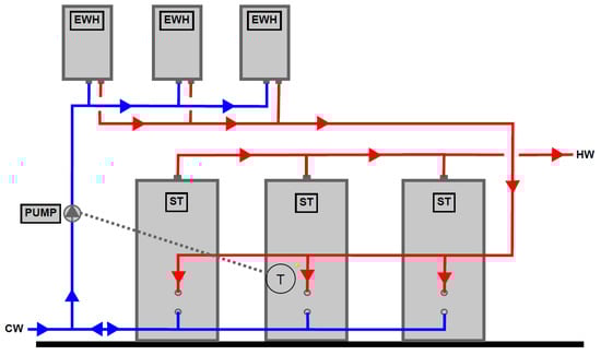
Figure 1.
Schematic diagram of the existing DHW system.
HPWHs transfer thermal energy from one source to water. This process is three to four times more efficient than an electric-resistance or fossil fuel water heating system. HPWHs utilizing a CO2 refrigeration cycle were chosen due to the low global warming potential of the refrigerant, the ability of this equipment to function outdoors through the conditions of a Seattle winter, and the high efficiency of the units. This system delivers a high coefficient of performance (COP) without using any fossil gas for DHW production. The selected HPWH was designed for the single-family housing market, but by organizing several HPWHs together, we were able to leverage this type of HPWH in larger multi-family buildings.
We designed a central plant for the target building that included four 15,000 BtuH (4.3 kW) Sanden CO2 heat pump water heaters (Model GUS-A45HPA), three existing storage tanks, a new 175-gallon (796-L) storage tank, three existing instantaneous electric water heaters and a pump, an existing building hot water circulation pump, and a new thermostatic tempering valve. This method made use of existing equipment to save money upfront and provide emergency backup. The retrofit was finished in 2018, and monitoring began in March 2019. The findings of the case study show that the target building was successfully converted to an HPWH domestic hot water system which is three times more efficient than the existing electric boiler system.
2.2. System Design
The HPWHs used in this project contain an R-744 refrigerant, commonly referred to as CO2. The efficiency and reliability of the Sanden HPWHs are reduced at higher inlet water temperatures [31]. The HPWHs’ power draw increases quickly when the inlet water temperature rises above about 100 °F (37.8 °C). Therefore, the design prioritized stratification and control strategies to keep the inlet water temperature below 100 °F (37.8 °C) for the majority of the HPWH heating cycle. Building hot water circulation pumps typically return water at 115 °F (46.1 °C) to the storage tanks. In DHW systems based on fossil gas or electric resistance, this warm water can return directly to primary storage tanks or primary heaters. However, the HPWHs will not respond well to or perform well with this warm inlet water temperature. Separating these two independent building DHW loads is a crucial design aspect of HPWH systems with hot water circulation systems. As a result, the DHW system design can prioritize sending cool water to the HPWHs while keeping the primary tanks thermally stratified. This leads to higher equipment efficiency, fewer cycles of heating equipment, and greater system reliability. There is a need for a separate system to maintain hot water in the distribution system (“temperature maintenance”) in this configuration.
The temperature maintenance tank—which was constructed as a “swing tank”—was a major innovation for the retrofit project. In this approach, high-temperature water (about 150 °F (65.5 °C)) is supplied from the primary storage tanks to the temperature maintenance tank. This water is combined with warm return water from the distribution system of the building. The tank temperature then “swings” from 120–150 °F (48.9–65.5 °C) to consistently provide the building with 120 °F (48.9 °C) water without the need for additional input heating.
Existing instantaneous electric water heaters will be used as a backup heating source. The present primary pump is controlled to be ON or OFF by a thermostat in the fourth storage tank (the temperature maintenance tank) based on the tank temperature. This water is pushed through three existing instantaneous electric water heaters before being returned to the fourth tank’s top. With this design, both the primary heating system (HPWHs) and the temperature maintenance heating system have a reliable backup system.
The HPWHs generate hot water at a temperature around 150 °F (65.5 °C), which is transported to the third storage tank’s top. In the storage tanks, adding hot water generates a useful temperature stratification. Cold city water enters the first storage tank at the bottom, which is closer to the HPWHs, thus resulting in both cooler incoming water and improved performance. As the HPWHs create high-temperature water, a thermostatic mixing valve was installed to prevent scalding and save energy.
Figure 2 provides a simplified schematic depicting the plant and the placement of monitoring equipment. The narrative in the following section delves deeper into the important characteristics of the HPWH DHW plant architecture.
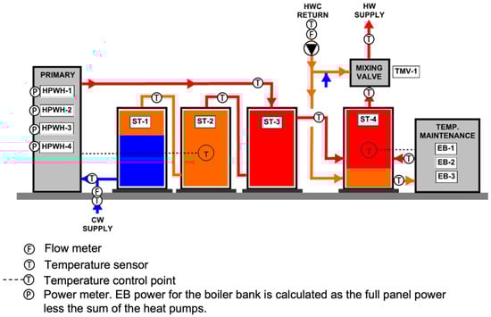
Figure 2.
HPWH plant schematic and monitoring equipment locations.
Single Pass: This design employs a “Single Pass” heat exchange technique rather than the more common “Multi-Pass” scheme used in most hydronic space heating applications. This means that a control valve or variable speed pump regulates the flow of water through the heat pump to maintain a target output temperature of 149 °F (65 °C). In contrast to the conventional fixed flow rate and fixed 10–20 °F (5.6–11.1 °C) temperature rise of the water, this results in a variable flow rate and variable temperature rise across the heat pump. With the incoming water temperatures ranging from 45–113 °F (7.2–45 °C), the heat pump can produce 149 °F (65.5 °C) water. The “Single Pass” approach has the advantage of constantly delivering usable water temperature to the top of the storage tank.
Multiple Storage Tanks: The foundation of this concept is the utilization of numerous storage tanks connected in series. With the warmest water at the end of the primary storage system, the series plumbing configuration allows for a high degree of temperature stratification throughout the system (ST-3). It also enables the use of smaller, less expensive tanks that are easier to install (and that can fit through the mechanical room door). The three existing tanks on the construction site were repurposed as primary storage tanks. A last tank (“swing tank”) was installed to serve as a dedicated temperature maintenance tank. As shown in Figure 2, this last tank is in series with the three primary tanks.
Swing tank: The swing tank design uses a non-stratified tank in series with the primary storage tanks. The swing tank temperature fluctuates between the hot storage water temperature (140–180 °F or 60–82 °C) and the hot water setpoint (~120 °F or ~49 °C). As water is used, the hot storage water flows into the swing tank adding heat. During periods of heavy use, the temperature of the swing tank will be highest because the hot storage water entering the tank will increase the swing tank temperature. During periods of low usage, the temperature of the swing tank will drop slowly. When the temperature gets too low, the electric resistance water heaters (EB-1,2,3) are turned on to ensure hot water will always be available to serve the building. The swing tank systems increase efficiency by allowing a significant portion of the temperature maintenance heating to be achieved via a primary single-pass heat pump [32].
Storage Temperature: The water is heated to a relatively high temperature (149 °F (65.5 °C)) to effectively increase the plant’s storage heating capacity, control possible legionella bacteria, and increase the effectiveness of the “swing tank” (ST-4 in Figure 2). To avoid scorching, outgoing water is cooled to 120 °F (48.9 °C) with recirculated water and/or incoming city water before being delivered to an apartment unit.
Temperature Maintenance Swing Tank: The temperature in this tank swings between 120 °F (48.9 °C) and 150 °F (65.6 °C) (ST-4 in Figure 2). During periods of high hot water demand, overheated (149 °F (65 °C)) water is transferred from the primary storage tank to the “swing tank”. The “swing tank” is kept primed above 120 °F (48.9 °C) by these repeated withdrawals. If the temperature in the “swing tank” falls below 120 °F (48.9 °C), the backup electric water heaters kick in to keep the temperature above 125 °F (51.7 °C).
Arrangement for Serial Primary and Temperature Maintenance Tanks: The series configuration allows for a “swing tank” design, which combines overheated water from the primary tanks with cooler recirculation water in the “swing tank.” The mixed temperature in the “swing tank” will be more than or equal to the desired use temperature if there is enough overheated water from the primary tanks. This method could work well with CO2 heat pumps and other heat pump cycles that provide large temperature increases to the water. No additional heat is required in the “swing tank” if enough hot water is used to compensate for the circulation loop losses. If more heat is required, resistive heating or a specialized heat pump can be used. Existing instantaneous electric resistance water heaters were used to provide this backup at the target building.
Back-up Electric Water Heaters: In this design, three existing instantaneous electric water heaters are used as backups. They are configured in parallel and operate together to provide 135 °F (57.2 °C) water to ST-4. The backup instantaneous electric water heaters activate in the following situations: when the final storage tank drops below 120 °F (48.9 °C) due to continued cooling from the recirculation system, when the incoming capacity from the HPWH is insufficient, or when hot water is not used for an extended period of time.
Controls: Because the HPWH system lacks a central DHW plant controller, each of the CO2 HPWHs runs in parallel with its own controls. Each CO2 HPWH has built-in control circuitry that turns the units on and off based on a thermocouple reading. Four thermocouples are attached to the HPWHs in the middle primary tank (ST-2). HPWHs are called on when tank temperature in the second tank drops below 113 °F (45 °C). This draws water from ST-1 at around city water temperature (60 °F (15.5 °C)). The HPWHs run in parallel drawing in the 60 °F (15.5 °C) water and discharging 149 °F (65 °C) water to the top of ST-3. This pushes hot water back through the in-series tanks, charging them with HW. When the inlet water temperature to the HPWHs reaches 122 °F (50 °C) the HPWHs stop the heating cycle. Then, they wait for ST-2 to drop below 113 °F (45 °C).
2.3. Measurement
The system for Measurement and Verification (M&V) integrates the electricity usage for each HPWH and electric resistance water heater, and it controls water flow and temperature measurements at strategic points (see Appendix A Table A1). Figure 2 shows the monitoring locations. The measured data were collected and averaged over one-minute intervals, and the following items were measured:
- Inlet and outlet water temperatures of the HPWH heaters;
- Inlet and outlet water temperatures of the electric boilers;
- Inlet and outlet water temperatures of the recirculation loop;
- Water temperatures exiting each storage tank;
- Flow of incoming city water;
- Flow in the recirculation loop;
- Temperature of city (cold) water entering the system;
- Electricity used to heat water (by each HPWH and the bank of three boilers); and
- Outdoor air temperature from a nearby National Oceanic and Atmospheric Administration (NOAA) weather station.
An online tool (https://ecotope.shinyapps.io/MFSandenRetrofit/ accessed on 21 May 2022) was developed to view raw data for each monitored point in the HPWH system, hourly and daily averages, and calculated values such as heat output and COP. The measured data is automatically updated every night, thus allowing engineers and installers commissioning projects to quickly receive feedback on the status of and changes to the system. This online tool has been available since spring 2019, and it was used to collect the data examined in the present work.
Although the M&V system was intended to collect data to evaluate annual system performance, data streams were essential for troubleshooting and allowed for early diagnosis of system operations issues. For example, in May 2019, a water leak was detected at the target building, and this leak was fixed in June. A few months after the repair, one of the HPWH units started entering an error status and going idle. Error codes indicated that the HPWH was shutting down to prevent operation at high temperatures. An on-site service visit determined that the incoming water filter (strainer) was clogged, thus causing the high-water-temperature alert. After the strainer had been cleaned and power was cycled to the unit, the equipment resumed proper function. Attributable to possible debris in the pipes from the leak repair earlier in the year, this error status occurred infrequently in the following months and was always promptly detected through the M&V data.
When the water supplied to the recirculation loop dropped below the set point for the backup electric resistance system, a similar operational issue was discovered: a mechanical contractor who performed maintenance on the boilers discovered that all of the flow sensors had failed because of blocked impellers (again likely due to debris from the leak repair). M&V data has been identified as a critical resource for detecting errors in and troubleshooting HPWH systems. The data facilitated communication with stakeholders and maintenance personnel while ensuring that the system was performing as designed.
3. Measurement Results
3.1. Water Temperatures Results
Figure 3 shows the water and air temperatures from 20 March 2019 through 20 March 2020 (The June 2019 leak was excluded). ‘Temp HPWH OUT’ is the outlet water temperature of the HPWH series and entering the third water tank (ST-3). ‘Temp HW’ is the hot water temperature delivered to the recirculation loop. ‘Temp CW’ is the city water temperature, which shows a seasonal change of a high of ~70 °F (21.1 °C) in August along with lower temperatures in the winter; the lowest temperatures are typically shown between January and February. ‘OAT NOAA’ is Outdoor Air Temperature (OAT) recorded by a nearby NOAA weather station. The outdoor air temperature shows a similar seasonal trend as ‘Temp CW’. The collected data shows that the incoming (50–72 °F (10–22.2 °C)) city water is heated to 147 °F (63.9 °C) and delivered to the recirculation loop at about 125 °F (51.7 °C), even during the periods when only three HPWHs were operable. The drop in the supply water temperatures seen from late January 2020 to early February 2020 corresponds to a period during which several HPWHs were out of operation. The backup electric boiler was not operating normally at the time due to reckless setpoint alterations and a defective flow sensor. These equipment problems were rectified in March and April of 2020.
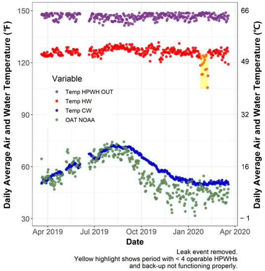
Figure 3.
Daily average temperature for air and water.
3.2. Water Use Results
Figure 4 shows the average hourly hot water demand in gallons per minute (GPM) for a weekday or a weekend day from the M&V data. Each date is displayed in light gray. The colored line represents the percentile of all data by time, and the median is the green line (50%). Several interesting facts were discovered from the measured data.
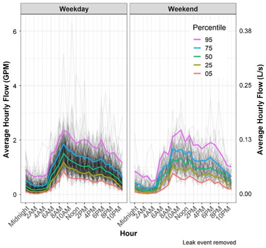
Figure 4.
Average water use by hour of day.
Overall, there is no significant difference between weekday and weekend usage patterns. On both weekdays and weekends, more water is used around 8–10 a.m. and again around 6 p.m. Multi-family buildings with many working occupants typically have lower mid-day water use on weekdays when their occupants are at work, and peaks that occur on weekend mornings may shift later. However, at the target site, the differences between weekdays and weekends, both daily and hourly, are less pronounced than in multi-family buildings with occupants working during the day; this is likely due to the senior population of the target site.
The measured flow data can also describe the annual water usage of the site. Just as outdoor air temperature and city water temperature follow seasonal cycles, the water consumption of residents also shows a seasonal cycle. Typically, the water usage of building occupants is higher during cooler months and lower when the weather is warmer. Regression analysis was used to estimate annual usage by estimating the daily delivered hot water for missing periods (approximately a week when the leak and repair resulted in inaccurate flow). A regression analysis was used with the average daily temperature over this period to predict the gallon per apartment metric, and this was then included in the measured data to calculate an annual estimate.
Figure 5 shows the regression analysis. The average hot water delivered is about 20 gallons (75.7 L) per unit per day. According to the building owner, the target building has one person per apartment.
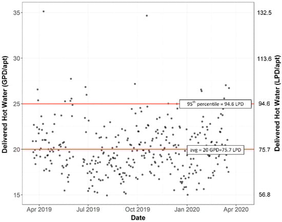
Figure 5.
Daily hot water consumption per occupant.
On this occupant basis, water use is slightly higher than reported in a previous study [33] of multi-family buildings with more working people, measured at 13–19 GPD (49.2–71.9 LPD) per capita. This may be attributed to the senior population of the building’s tenants, who spend more time at home than in multi-family buildings where residents spend more time at work.
The 95th percentile of daily flow indicates that occupants can use an average of 25 gallons (94.6 L) or more per unit per day (Figure 5). The maximum average daily usage is 35 gallons (132.5 L) per unit per day, which is nearly double the target building average. This emphasizes the significance of incorporating a backup heat system in addition to the HPWH system. Without the backup heat capacity, the HPWH systems would need to be sized to meet approximately double the average demand to provide unlimited hot water throughout the year.
3.3. DHW System Performance
The performance of the DHW system is a key performance measure in this field study. According to the manufacturer data [34], the individual Sanden CO2 heat pump water heater (Model GUS-A45HPA) has a COP over 2.0 at 5 °F (−15 °C) and over 4.0 at 67 °F (19.4 °C). The central HPWH system is designed to record all energy inputs and outputs to water heating and distribution (recirculation) systems. This includes equipment for primary water heating and temperature maintenance heating (including backup water heaters).
The annual performance of the DHW system can be estimated as follows:
where, is the heat transferred to the building’s water supply. is the heat loss of circulation loop, is the primary HPWH, and is the backup heater.
Figure 6 depicts the DHW SysCOP during the monitoring period. Each dot represents the average COP over three-day periods. The DHW SysCOP is defined as the thermal energy required to heat the incoming water to its delivery temperature and the thermal energy required to compensate for losses in the recirculation loop divided by all the electrical energy required to power the heat pumps and backup electric resistance boilers.
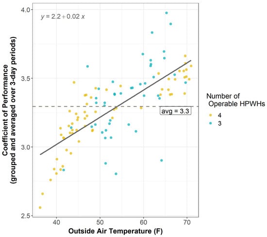
Figure 6.
DHW system COP by outdoor air temperature.
It is separated into two sections: one with all four heat pumps operational and one with only three heat pumps operational. With only three heat pumps running, the system was still able to maintain its efficiency.
3.4. Duty Cycle of HPWH
The equipment manufacturer recommended that systems should be designed not to operate for more than 16 h a day in general. Figure 7 (Outliers removed, values over 24-h/day could occur if the HPWH ran for >1 day consecutively, median shown in red) presents that, when all HPWHs were operational, each equipment typically ran for about 15 h. With fewer working HPWHs, the running time increased to about 20 h per day.
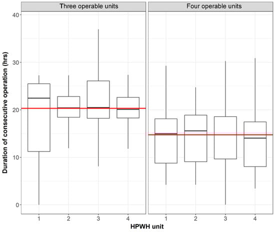
Figure 7.
HPWH run times according to operable HPWHs.
A total of 90% of the time, the heat pumps worked for less than 24 h (even with three or four operable units). In the most severe circumstances, the HPWHs operated for multiple consecutive days. This was seen at the end of May 2019 after a leak was discovered at the location. In February 2020, two HPWHs were dysfunctional, and the backup system was inactive; at that time, a device was operational for five days.
One of the considerations for future designs is to add an additional heat pump above its strict capacity to handle the design load. The additional equipment costs shall be balanced with the contribution of the added heat pump: reduced operation hours under normal conditions, less contribution from backup systems, and recovery during periods of failure of one or two heat pumps.
3.5. Temperature Maintenance and Swing Tank Operation
Due to the size of the entrance to the mechanical room of the target building, the “swing tank” is minimum-sized. Nevertheless, because of the reduced recirculation loop losses, the tank size is nearly ideal. The “swing tank” purpose is to reduce the use of backup electric water heaters to maintain the recirculation loop delivery temperature. It performs best when all HPWHs are operational (and when the design capacity of 150 °F (65.6 °C) water is given), the tenant draw pattern is around 20 gallons (75.7 L) per apartment per day, and the occupant usage keeps the “swing tank” primed and above the 125 °F (51.7 °C) delivery temperature. When the outdoor conditions or draw pattern departs from the criteria of design, the backup electric resistance water heaters are activated to maintain recirculation temperatures within the setpoint ranges. Further, if the HPWHs are not functioning as intended or if the demand pattern exceeds the design load, then the EWH boilers can fulfill the building’s required hot water usage.
During the monitoring period, the majority of HPWHs performed perfectly, although one or more HPWHs were inoperable on occasion. Figure 8 shows the EWH usage over the period with three operational HPWHs (before 11 April 2019) and that with four operational HPWHs (until 22 April 2019). When three HPWHs were operated, the backup electric water heater operated frequently, but when four HPWHs were operated, the operation frequency decreased. The backup boilers were measured to be running minimally when the HPWHs was operating as intended (to the right of the red vertical line).
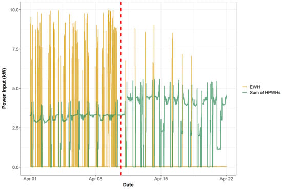
Figure 8.
Power Input (kW) with three (left of the red line) and four operable HPWHs.
Further, when all HPWHs were accessible, the “swing tank” was maintained at a more constant temperature. During the period when only three HPWHs were operating, the average daily temperature of the water exiting the “swing tank” was lower and had greater variability. This is as expected, because the three HPWHs take longer to recharge the storage tank with 150 °F (65.6 °C) water, and the electric boilers are set to maintain the recirculation loop temperature (not the superheated water provided by the HPWH).
3.6. Backup System
Existing electric resistance water heaters were maintained at the target building to provide backup to maintain temperature managed by the “swing tank” and support in case of HPWH failure. As displayed in Figure 8, the electric boilers were required for both duties during monitoring at this site. However, the boilers only supplied about three percent of the water’s total heat (since the electric boilers were impaired and not entirely functioning at the conclusion of the monitoring period, the calculations were based on the first half of monitoring). In this project, where electric boilers already existed at the target site, it was effective to keep the existing electric boilers as a backup system. If a future project were to install an additional heat pump stage and a larger “swing tank”, it may not require a full backup.
3.7. Financial Analysis
Table 1 displays the costs and business cases for retrofitting an existing electric water heating system with a central heat pump water heating system.

Table 1.
Calculations of HPWH retrofit installation costs.
The table describes the baseline existing electric water heater scenario for water heating and hot water circulation reheat, as well as the retrofit HPWH system handling both water heating and reheat loads. The overall cost of installation is comprised of more equipment (HPWH units, an additional storage tank, and a thermostatic mixing valve), engineering fees, and additional plumber work. The cost of this project was relatively high compared to what one would expect in a well-established market. The HPWHs have a 20-year operating lifetime.
The simple payback year for retrofit HPWH systems without utility incentives is 18.3 years. For typical projects, the local utility provides an incentive of USD 500 per apartment for this type of equipment, which reduces the payback period to 13.6 years. Based on the smaller HPWH systems that have more recently been installed in the Seattle area (which will be discussed in the next section), the cost of the retrofit system in the target building was significantly higher than the cost of such installation. However, the system is still cost-effective (including original installation costs and potential incentives), and the payback period is within 15 years of the expected lifetime of the equipment.
The installation and engineering/design costs for this particular project were fully subsidized by the City of Seattle’s Office of Housing HomeWise Weatherization Program (https://www.seattle.gov/housing/homeowners/weatherization accessed on 21 May 2022). Various incentive programs are available to balance payback periods for possible retrofit and new construction projects, thus making heat pump water heaters an attractive and effective option.
4. Key Design Principles
The key design considerations for the HPWH retrofit design of the target building are:
- This study has demonstrated that DHW for a large residential building can be supplied from a remarkably small heat pump plant. The hot water used in the 60 households in the target building is supplied with a nominal capacity of 5 tons, and it can be used for a long time with a capacity of less than 4 tons. Designing to industry standards leads to much larger systems. This can be demonstrated by the capacity of electric resistance water heaters of 120 kW design in the existing system. This is more than five times the current output capacity.
- HPWHs and water storage systems should be sized according to the “Low water usage” methodology of ASHRAE 2015.
- The number of HPWHs specified was based on the building hot water load and the existing storage tanks at the site. The engineering team specified four HPWHs which include one redundant (or backup) HPHW. This proved to be a good design as multiple times one of the four HPWHs had issues. The tenants did not realize the issue or have HW issues due to the redundancy in equipment specified. Redundancy is common in gas and electric resistance system. This approach should be used for HPWH systems as the equipment can have longer lead times than GWHs or EWHs.
- Storage and controls must be configured to store large amounts of cold water before starting the heat pumps. That way, the heat pump does not get the water too hot and allows for longer cycle lengths, which can result in reduced efficiency and higher head pressure. The location of the thermostat is also very important: It must be positioned far enough away from the incoming water to prevent the thermostat from tripping whenever water is used.
- The hydraulic layout configured the HPWHs in parallel, similar to the existing EWH hydraulic layout. The storage tanks were reconfigured into a series layout to prioritize stratification. This also leads to a higher effective storage volume for all tanks.
- If a building has a hot water recirculation system, temperature maintenance consumes a significant portion of the system’s energy usage, so using electrical resistance greatly reduces efficiency. Returning a lot of warm water from the recirculation loop to the primary reservoir and HPWHs degrades the performance of the system. An effective way to alleviate this is to decouple the temperature maintenance load from the primary load so that the primary HPWH system can run at maximum efficiency.
- The heat lost through circulation loop and distribution pipework can account for 25 through 50% of the total heat required for the water heating system. If possible, all areas of thermal bridges should be removed, and the circulation and distribution piping insulation should be strengthened.
- Conventional non-electric tempering valves do not perform well at various inlet water temperatures. One should thus consider using electronic tempering valves.
- The “swing tank” design philosophy is a proven concept and works to minimize the electric resistance temperature maintenance of the recirculation loop.
- When possible, in retrofit projects, repurposing existing equipment (e.g., the original system for backup, storage tanks, or recirculation reheat) can reduce the initial costs.
- In any emerging technology design, it is important to include robust measurement, verification, monitoring, and automatic alerts to building personnel upon detection of a fault in the HPWH system to assist in the diagnosis of issues and the improvement of future designs.
5. Conclusions and Recommendations
The project in this paper demonstrated that HPWHs can achieve significant energy savings in multifamily buildings in the Pacific Northwest climate in the United States. The case study also demonstrated that a residential-scale CO2 HPWH plant can be successfully applied to multi-family residential buildings, and that the “swing tank” concept is an efficient design for dealing with building hot water circulation loop heat losses.
The test case was a 60-unit apartment building, but the same approach could be extended to apply to larger buildings. Based on the findings of this study, laboratory testing, and additional HPWH M&V projects, an online HPWH sizing and education tool has been developed (Ecosizer (https://ecosizer.ecotope.com/sizer/, accessed on 23 February 2022)). The Ecosizer allows standardized sizing for “swing tank” and other HPWH system configurations in multifamily applications.
Long-term measurements and verifications in the target building yielded the following insights:
- Annual monitoring showed that the DHW system had an average coefficient of performance of 3.3. The annual operating results showed that HPWHs used an average of 68 kWh/day.
- The average water use at this location is 20 GPD (75.7 LPD) per apartment or per person (as each apartment had one occupant in this case). This is slightly greater than earlier multifamily studies of bigger market-rate buildings, which indicated values of 13–19 GPD (49.2–71.9 LPD) per person [33]. Further, this site’s peak demand periods are less pronounced, and weekend and weekday usage are nearly identical. The increased usage and shifted daily patterns are likely due to the retired senior demographic at this building versus the workforce populations at the other sites that have previously been studied.
- Although the installed M&V metering equipment was primarily designed to evaluate the performance of the equipment, it also served to diagnose and resolve operational issues. Without the M&V equipment, it would have been impossible to detect and address system concerns promptly. Future designs of central heat pump water heating systems should include a method for automatic remote alarms to be transmitted to building owners and maintenance people to avoid lengthy durations of backup heating equipment operation (current generation products from this (and other) HPWH manufacturers now offer automatic remote alarming functions for equipment faults as well as low delivery temperatures, with additional alarms that can be configured by the user).
- With the introduction of the “swing tank” concept, warm recirculation water has been successfully separated from the HPWH. The water tank specializing in temperature maintenance was designed and sized as a “swing tank” that uses overheated water from primary water storage tanks to mix with cooler water returning from the recirculation loop. The over-heated water from the primary tanks was periodically drawn into the “swing tank” to keep it above the temperature at which the backup electric boiler would start operating. This idea was found to be a successful strategy in this site because it minimized the reheating of the electric resistance heaters and the circulation loss was small.
- The existing electric resistance water heaters were preserved during the HPWH retrofit with the aim of assisting “swing tank” operation and providing backup water heating in the case of equipment failure. During the monitoring period of this site, the operation of electric water heaters was confirmed for both of these tasks, but the electric water heaters contributed only about 3% of the total water heating energy. Future projects can avoid using a full backup by installing an additional redundant stage of heat pumps and a larger “swing tank”.
- The median run times with four operable heat pumps were 15 h per day, which was 63% of the duty cycle. This includes the warmest environment and the coldest environmental conditions, summer and winter. Having fewer operable units led to longer median duty cycles (83% or 20 h). In extreme situations, such as when a leak occurs and multiple heat pumps fail, the uptime can exceed 24 h.
- The increasing costs of HPWH systems are still high compared to those of conventional equipment; however, the cost of heat pump water heating systems is expected to drop significantly as the product enters the mainstream market. Until then, payback periods for early adoption can be reduced through utilities and other incentive programs. However, even without incentives, the high efficiency of the HPWH system provides significant energy savings and reduced operating costs, making it an attractive water heating option for renovations and new construction.
- The average hot water usage on the peak day was almost double the daily average usage. Therefore, the HPWH system designers should consider the integration of less expensive backup electrical resistance water heaters. This allows for cost-effective operation on most days and smoother hot water supply to residents on fewer peak days.
Future research and product development recommendations include:
- For the designs and applications of future “swing tanks”, a method for predicting recirculation losses is needed so that the reliable sizing of the temperature maintenance system can be achieved. This requires further studies into temperature maintenance systems and recirculation losses.
- Extend the application of this hot water technology through additional pilot studies in other multi-family buildings (low- and medium-rise buildings) and contribute to the utility’s program planning. In particular, future pilots should incorporate redundant heat pump stages and automatic alert capabilities.
- This project included the minimum heat pump capacity required to deliver the project. During the study, the site experienced intermittent periods in which one or more HPWHs were inoperable. This problem could often be swiftly resolved by mechanical contractors or skilled maintenance staff. However, the inclusion of additional CO2 HPWH units in the system design provides some measure of resilience to the output capacity. This could reduce the overall HWPH run times and further reduce backup system operation, as well as provide adequate heat pump capacity for periods when one of the units is offline. There is a need for future studies examining the impacts of this “factor of safety” approach to HPWH system design on cost and performance.
- The installation of initial emerging technology should include a level of M&V equipment to detect and solve possible problems.
Author Contributions
Conceptualization, J.H.; methodology, A.B. and C.G.; validation, A.B., C.G. and H.L.; formal analysis, A.B.; writing—original draft preparation, A.B. and C.G.; writing—review and editing, J.H. and H.L.; visualization, A.B., C.G. and H.L.; supervision, J.H.; funding acquisition, J.H. and H.L. All authors have read and agreed to the published version of the manuscript.
Funding
The research was supported by Bonneville Power Administration (BPA). Ecotope (115761 G003965) was under subcontract to Washington State University’s subcontract (00071419). The publishing process of this work was supported by the National Research Foundation of Korea (NRF) grant funded by the Korea government (MSIT) (No. 2021R1F1A1057904).
Institutional Review Board Statement
Not applicable.
Informed Consent Statement
Not applicable.
Data Availability Statement
The data presented in this study are available in the article.
Acknowledgments
We would like to thank the following people and entities for their contributions to this study: Bonneville Power Administration’s E3T program for over a decade of support for heat pump water heaters. Community Roots (formerly Capitol Hill Housing) for pursuing a heat pump water heater system for their retrofit and allowing Ecotope to perform this case study at their property. The City of Seattle Office of Housing for first initiating the heat pump water heater analysis in 2014 and for funding the retrofit project. Emerald Cities Seattle for bringing us back into the building in 2017 for another look at a heat pump water heater retrofit. John Miles, General Manager at Sanden International, for sharing his in-depth product knowledge with our team.
Conflicts of Interest
The authors declare no conflict of interest.
Appendix A
Table A1.
Measurement Instrument Specification.
Table A1.
Measurement Instrument Specification.
| Measurement Items | Instrument Model | Specifications |
|---|---|---|
| Water meter | EKM-SPWM-200-CF | Pulse rate: 1 pulse/0.10 ft3 (1 pulse/0.003 m3) Accuracy: ±5% from Qmin to Qt, ±2% from Qt to Qs Minimum flow (Qmin): 15.89 ft3/h (0.45 m3/h) Transitional Flow (Qt): 105.94 m3/h Overload flow (Qs): 1059.44 ft3/hr (30 m3/h) Temperature range: 32–122℉ (0–50 °C) |
| Data logger | EG4130 | AC Voltage: L1: 85–277 Vrms L2: 0–277 Vrms L3: 0–277 Vrms DC Voltage: 42 Vrms Power: 9–60 Vdc Measurement: +/−60 Vdc |
References
- US EIA. 2015 RECS Survey Data. 2015. Available online: https://www.eia.gov/consumption/residential/ (accessed on 21 May 2022).
- US EIA. Use of Energy Explained Energy Use in Homes. 2015. Available online: https://www.eia.gov/energyexplained/use-of-energy/homes.php (accessed on 21 May 2022).
- Nijs, W.; Tarvydas, D.; Toleikyte, A. EU Challenges of Reducing Fossil Fuel Use in Buildings; Publications Office of the European Union: Luxembourg, 2021. [Google Scholar] [CrossRef]
- Zhang, J.-F.; Qin, Y.; Wang, C.-C. Review on CO2 heat pump water heater for residential use in Japan. Renew. Sustain. Energy Rev. 2015, 50, 1383–1391. [Google Scholar] [CrossRef]
- Zheng, X.; Wei, C.; Qin, P.; Guo, J.; Yu, Y.; Song, F.; Chen, Z. Characteristics of residential energy consumption in China: Findings from a household survey. Energy Policy 2014, 75, 126–135. [Google Scholar] [CrossRef]
- Energy Information Administration (EIA). About the Residential Energy Consumption Survey (RECS) Table HC8.1 Water Heating in U.S. Homes by Housing Unit Type, 2015. Energy Inf. Adm. 2015. Available online: https://www.eia.gov/consumption/residential/data/2015/hc/php/hc8.1.php (accessed on 26 February 2022).
- Treichel, C.; Cruickshank, C.A. Energy analysis of heat pump water heaters coupled with air-based solar thermal collectors in Canada and the United States. Energy 2021, 221, 119801. [Google Scholar] [CrossRef]
- Li, H.; Sun, Y. Performance optimization and benefit analyses of a photovoltaic loop heat pipe/solar assisted heat pump water heating system. Renew. Energy 2018, 134, 1240–1247. [Google Scholar] [CrossRef]
- Shan, M.; Yu, T.; Yang, X. Assessment of an integrated active solar and air-source heat pump water heating system operated within a passive house in a cold climate zone. Renew. Energy 2016, 87, 1059–1066. [Google Scholar] [CrossRef]
- Buker, M.S.; Riffat, S.B. Solar assisted heat pump systems for low temperature water heating applications: A systematic review. Renew. Sustain. Energy Rev. 2016, 55, 399–413. [Google Scholar] [CrossRef]
- Chyng, J.; Lee, C.; Huang, B. Performance analysis of a solar-assisted heat pump water heater. Sol. Energy 2003, 74, 33–44. [Google Scholar] [CrossRef]
- Huchtemann, K.; Müller, D. Evaluation of a field test with retrofit heat pumps. Build. Environ. 2012, 53, 100–106. [Google Scholar] [CrossRef]
- Marinelli, S.; Lolli, F.; Butturi, M.A.; Rimini, B.; Gamberini, R. Environmental performance analysis of a dual-source heat pump system. Energy Build. 2020, 223, 110180. [Google Scholar] [CrossRef]
- Chao, S.; Yiqiang, J.; Yang, Y.; Shiming, D.; Xinlei, W. A field study of a wastewater source heat pump for domestic hot water heating. Build. Serv. Eng. Res. Technol. 2012, 34, 433–448. [Google Scholar] [CrossRef]
- Hepbasli, A.; Biyik, E.; Ekren, O.; Gunerhan, H.; Araz, M. A key review of wastewater source heat pump (WWSHP) systems. Energy Convers. Manag. 2014, 88, 700–722. [Google Scholar] [CrossRef]
- Grist, C.; Heller, J.; Banks, A.; Spielman, S.; Davis, B. Sitka Apartments Wastewater Heat Pump Measurement and Verification. 2020. Available online: https://www.bpa.gov/-/media/Aep/energy-efficiency/emerging-technologies/sitka-wwhpwh-report.pdf (accessed on 21 May 2022).
- Willem, H.; Lin, Y.; Lekov, A. Review of energy efficiency and system performance of residential heat pump water heaters. Energy Build. 2017, 143, 191–201. [Google Scholar] [CrossRef] [Green Version]
- Atasoy, E.; Çetin, B.; Bayer, Ö. Experiment-based optimization of an energy-efficient heat pump integrated water heater for household appliances. Energy 2022, 245, 123308. [Google Scholar] [CrossRef]
- Shen, B.; Nawaz, K.; Elatar, A. Parametric studies of heat pump water heater using low GWP refrigerants. Int. J. Refrig. 2021, 131, 407–415. [Google Scholar] [CrossRef]
- Ibrahim, O.; Fardoun, F.; Younes, R.; Louahlia-Gualous, H. Review of water-heating systems: General selection approach based on energy and environmental aspects. Build. Environ. 2014, 72, 259–286. [Google Scholar] [CrossRef]
- Nawaz, K.; Shen, B.; Elatar, A.; Baxter, V.; Abdelaziz, O. Performance optimization of CO2 heat pump water heater. Int. J. Refrig. 2018, 85, 213–228. [Google Scholar] [CrossRef]
- Lorentzen, G. Revival of carbon dioxide as a refrigerant. Int. J. Refrig. 1994, 17, 292–301. [Google Scholar] [CrossRef]
- Lorentzen, G. The use of natural refrigerants: A complete solution to the CFC/HCFC predicament (Utilisation des frigorigénes naturels: Une solution complete au problme des CFC et des HCFC). Int. J. Refrig. 1995, 18, 190–197. [Google Scholar] [CrossRef]
- Yokoyama, R.; Shimizu, T.; Ito, K.; Takemura, K. Influence of ambient temperatures on performance of a CO2 heat pump water heating system. Energy 2007, 32, 388–398. [Google Scholar] [CrossRef]
- Yokoyama, R.; Wakui, T.; Kamakari, J.; Takemura, K. Performance analysis of a CO2 heat pump water heating system under a daily change in a standardized demand. Energy 2010, 35, 718–728. [Google Scholar] [CrossRef]
- Rony, R.; Yang, H.; Krishnan, S.; Song, J. Recent Advances in Transcritical CO2 (R744) Heat Pump System: A Review. Energies 2019, 12, 457. [Google Scholar] [CrossRef] [Green Version]
- Dai, B.; Qi, H.; Dou, W.; Liu, S.; Zhong, D.; Yang, H.; Nian, V.; Hao, Y. Life cycle energy, emissions and cost evaluation of CO2 air source heat pump system to replace traditional heating methods for residential heating in China: System configurations. Energy Convers. Manag. 2020, 218, 112954. [Google Scholar] [CrossRef]
- Energy350. CO2 Integrated Heat Pump Water Heater Performance Report. 2018. Available online: https://energy350.com/wp-content/uploads/2018/11/CO2-Integrated-Heat-Pump-Water-Heater-Performance-Report-FINAL.pdf (accessed on 21 May 2022).
- CO2 Takes Heat Pump Water Heaters to the Next Level—Zero Energy Project, (n.d.). Available online: http://zeroenergyproject.org/2017/05/22/CO2-takes-heat-pump-water-heaters-next-level/ (accessed on 21 May 2022).
- Banks, A.; Grist, C.; Heller, J. CO2 Heat Pump Water Heater Multifamily Retrofit: Seattle WA. 2020. Available online: https://www.bpa.gov/EE/Technology/EE-emerging-technologies/Documents/CO2_Heat_Pump_Water_Heater_Final.pdf. (accessed on 21 May 2022).
- Larson, B.; Lodgson, M.; Kvaltine, N. Laboratory Assessment of Combination Space and Water Heating Applications of a CO2 Heat Pump Water Heater. Available online: https://energy.wsu.edu/Documents/Sanden_Combi_HPWH_lab_report_final_2016-07-05.pdf (accessed on 21 May 2022).
- Spielman, S.; Heilbrunn, L.; Heller, J. Nyle e60A R513a HPWH Feasibility Study. 2021. Available online: https://www.nyle.com/wp-content/uploads/2022/01/FINAL_20211020-Nyle-Feasibility-Study.pdf (accessed on 21 May 2022).
- Heller, J.; Oram, S. RCC Pilot Project: Multifamily Heat Pump Water Heaters in Below Grade Parking Garages in the Pacific Northwest, Bonneville Power Administration (BPA). 2015. Available online: https://ecotope-publications-database.ecotope.com/2015_004_RCCPilotMFHPWH.pdf (accessed on 21 May 2022).
- Sanden International (USA) Inc. Sanden SANCO2 Heat Pump Water Heater Technical Information. 2017. Available online: https://www.sandenwaterheater.com (accessed on 21 May 2022).
Publisher’s Note: MDPI stays neutral with regard to jurisdictional claims in published maps and institutional affiliations. |
© 2022 by the authors. Licensee MDPI, Basel, Switzerland. This article is an open access article distributed under the terms and conditions of the Creative Commons Attribution (CC BY) license (https://creativecommons.org/licenses/by/4.0/).