
An MHD Flow of Non-Newtonian Fluid Due to a Porous Stretching/Shrinking Sheet with Mass Transfer

 , , and
Abstract
:1. Introduction
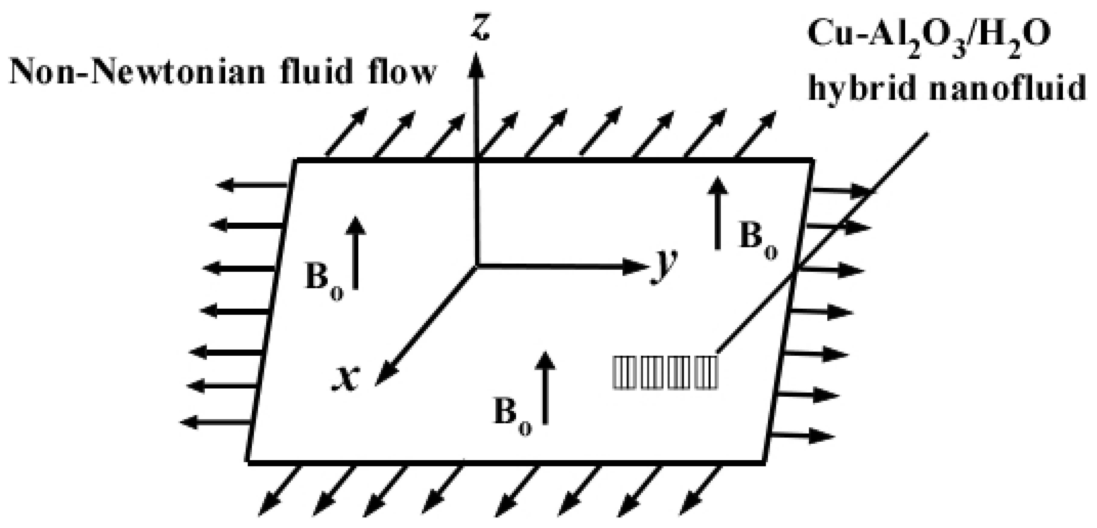
2. Physical Model
- The velocity in the axial direction is much larger than that in the transverse direction, i.e.,
- The velocity gradient in the transverse direction is much bigger than the velocity gradient in the axial direction.
2.1. Analytical Solution of Momentum Problem
2.2. Analytical Solution of Mass Transfer Problem
3. Results and Discussion
4. Conclusions
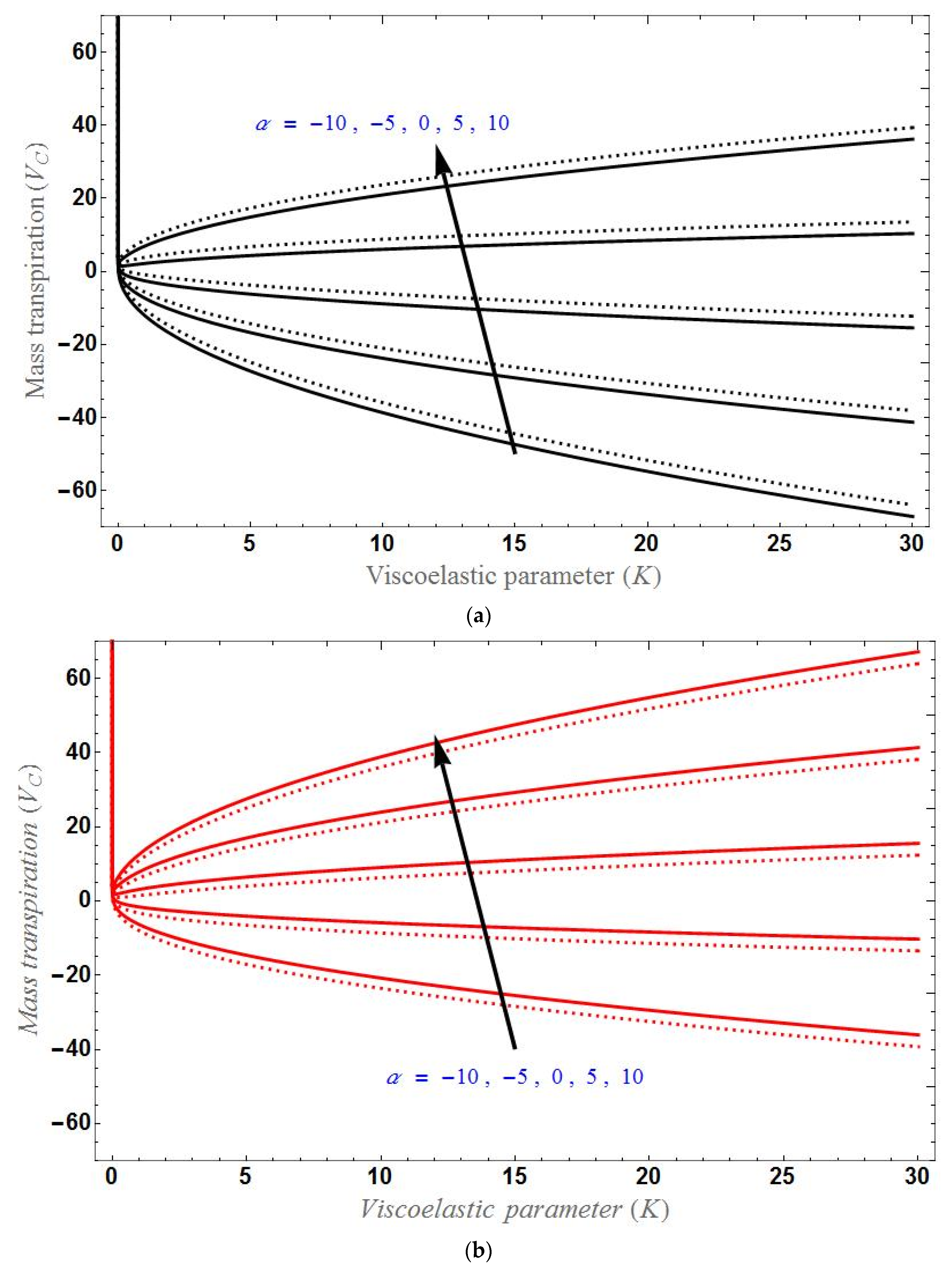
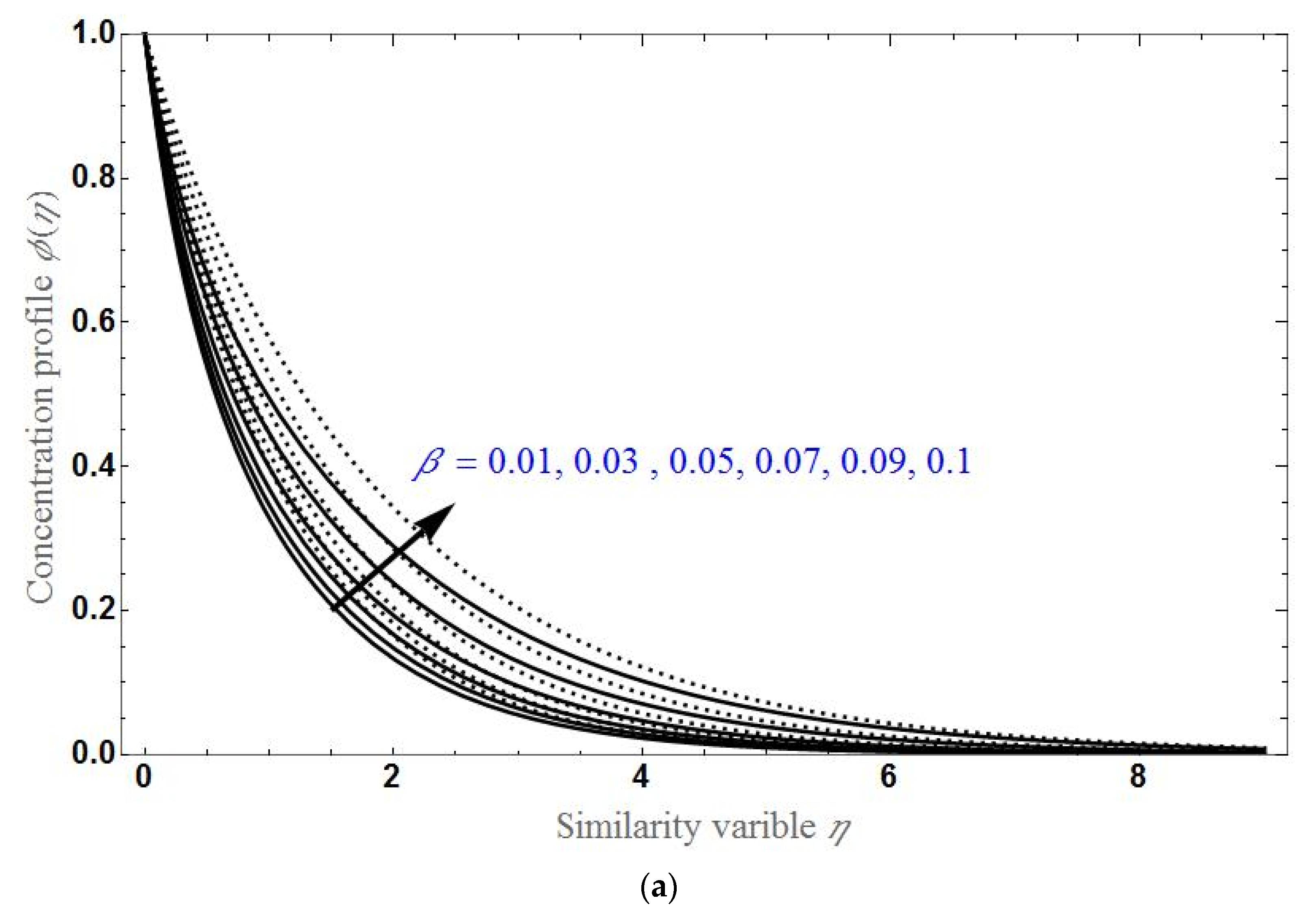
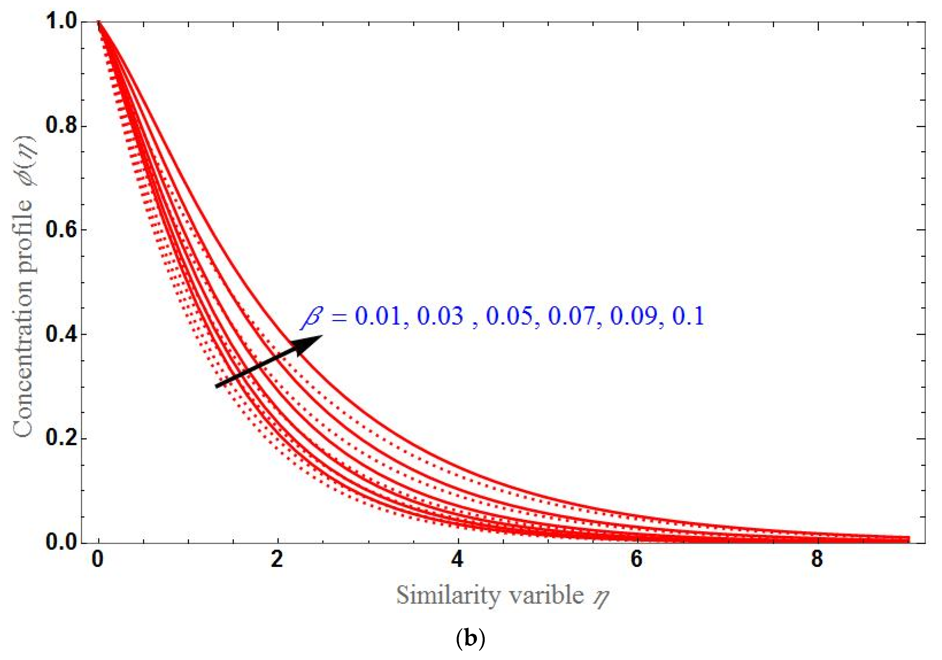
- As the parameter increases, mass transpiration also increases in both the stretching and shrinking cases.
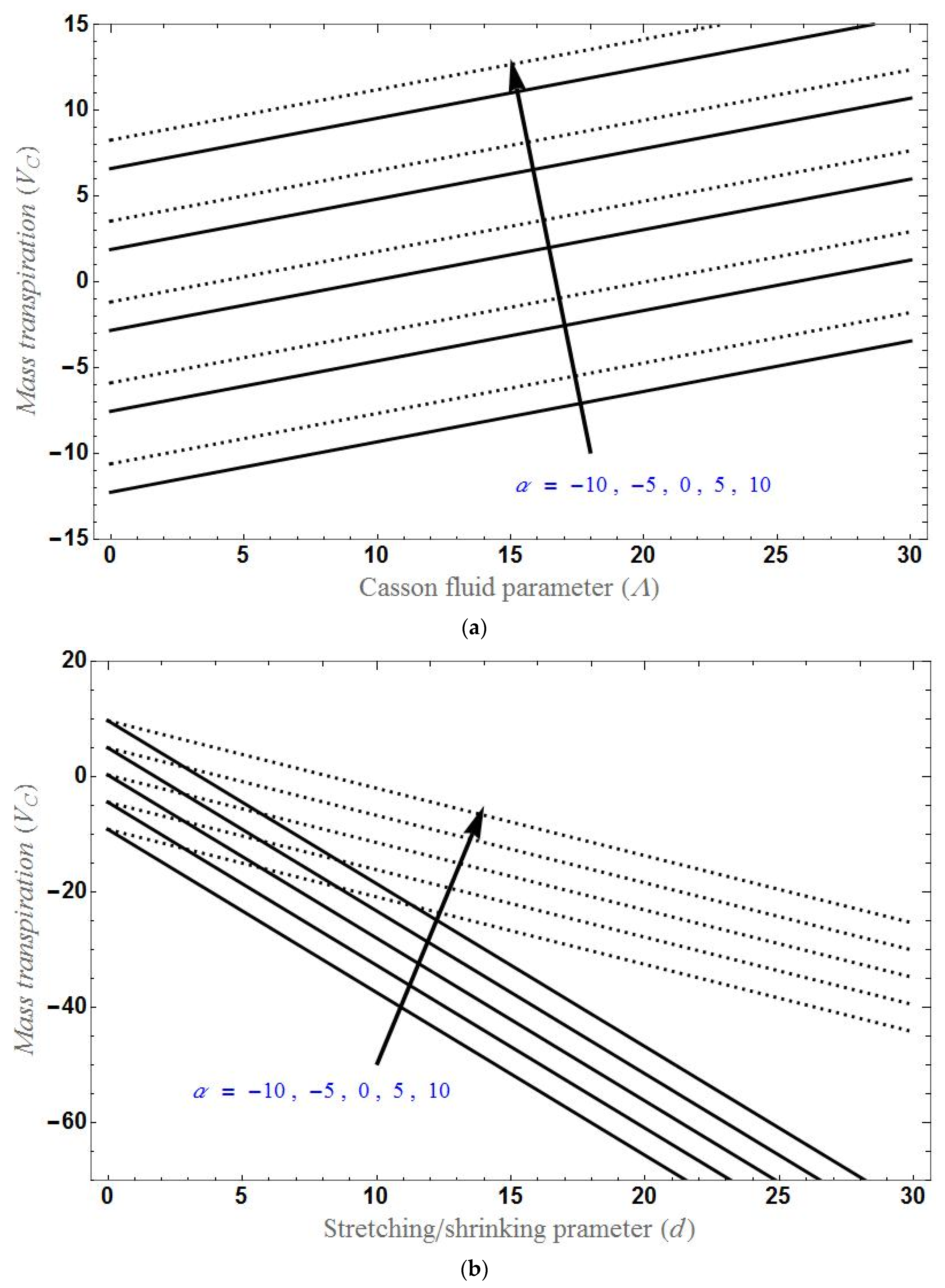
- Mass transpiration increases with increases in Casson fluid parameter and slip factor, and will decreases as increases.
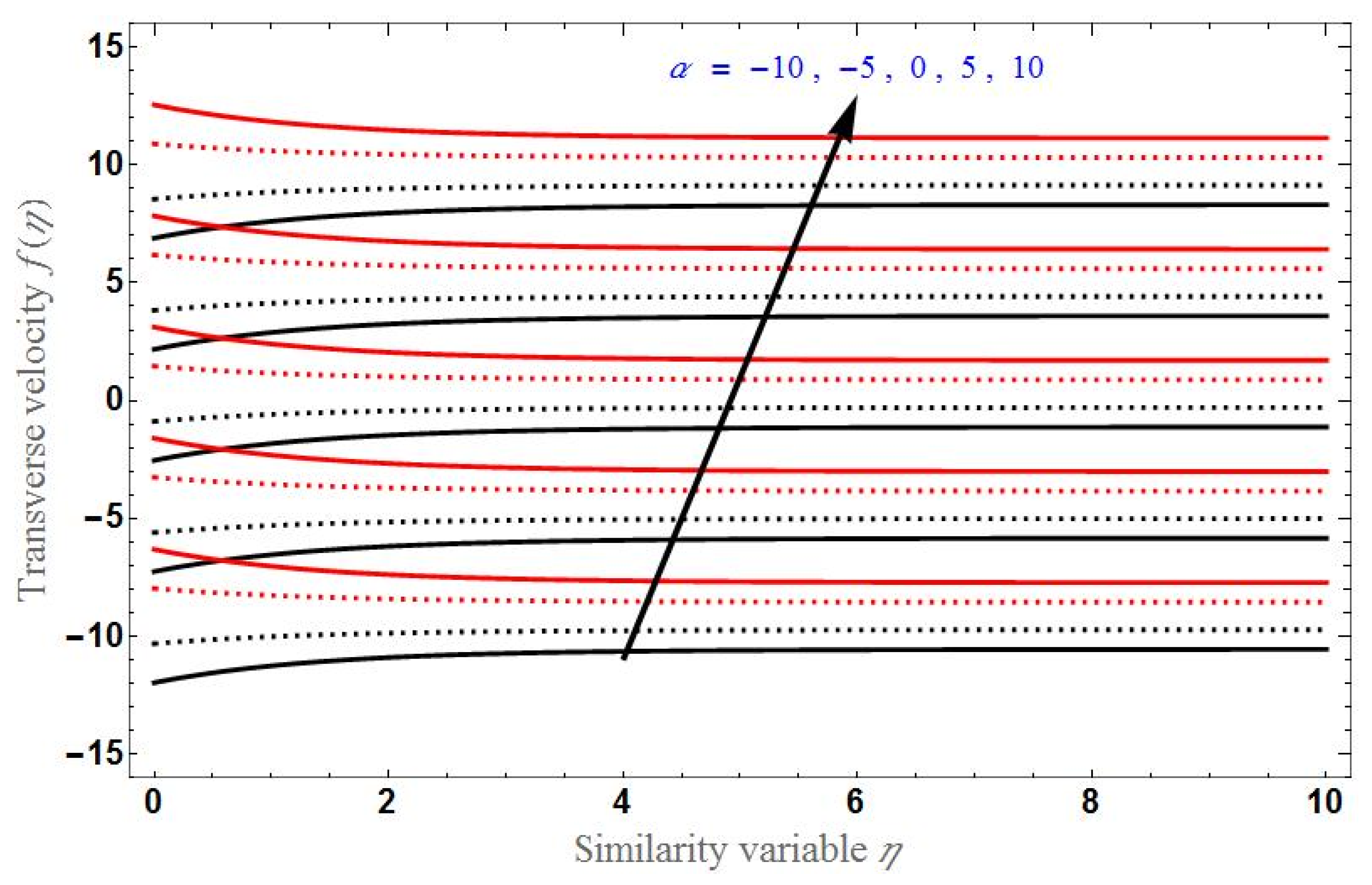
- Transverse velocity will be higher for higher values of the slip factor in the stretching case and lower for higher values of the slip factor in the shrinking case.
- Axial velocity expands with or d for the stretching case and shrinks with or d for the shrinking case. The effect is reversed while varying .
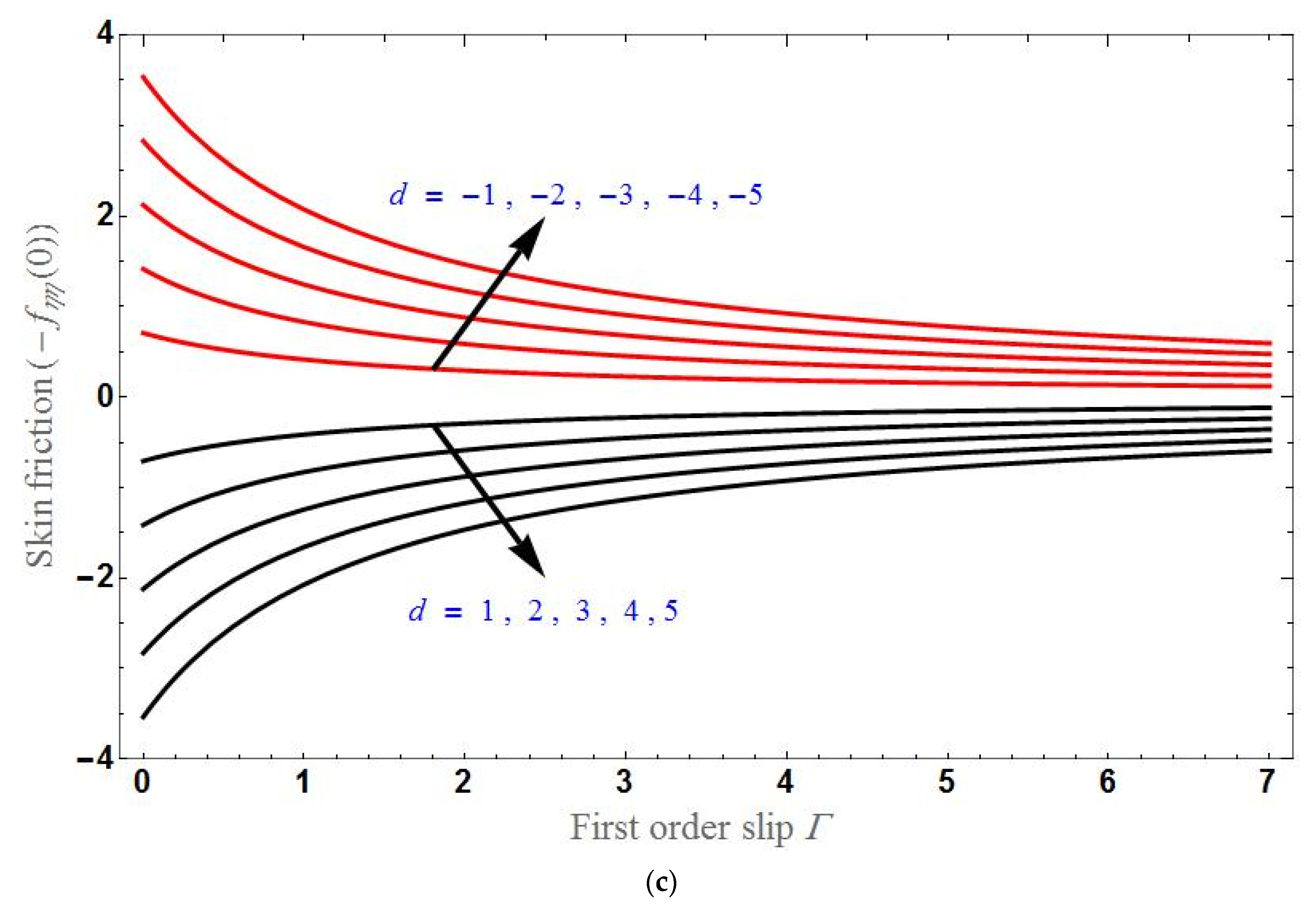
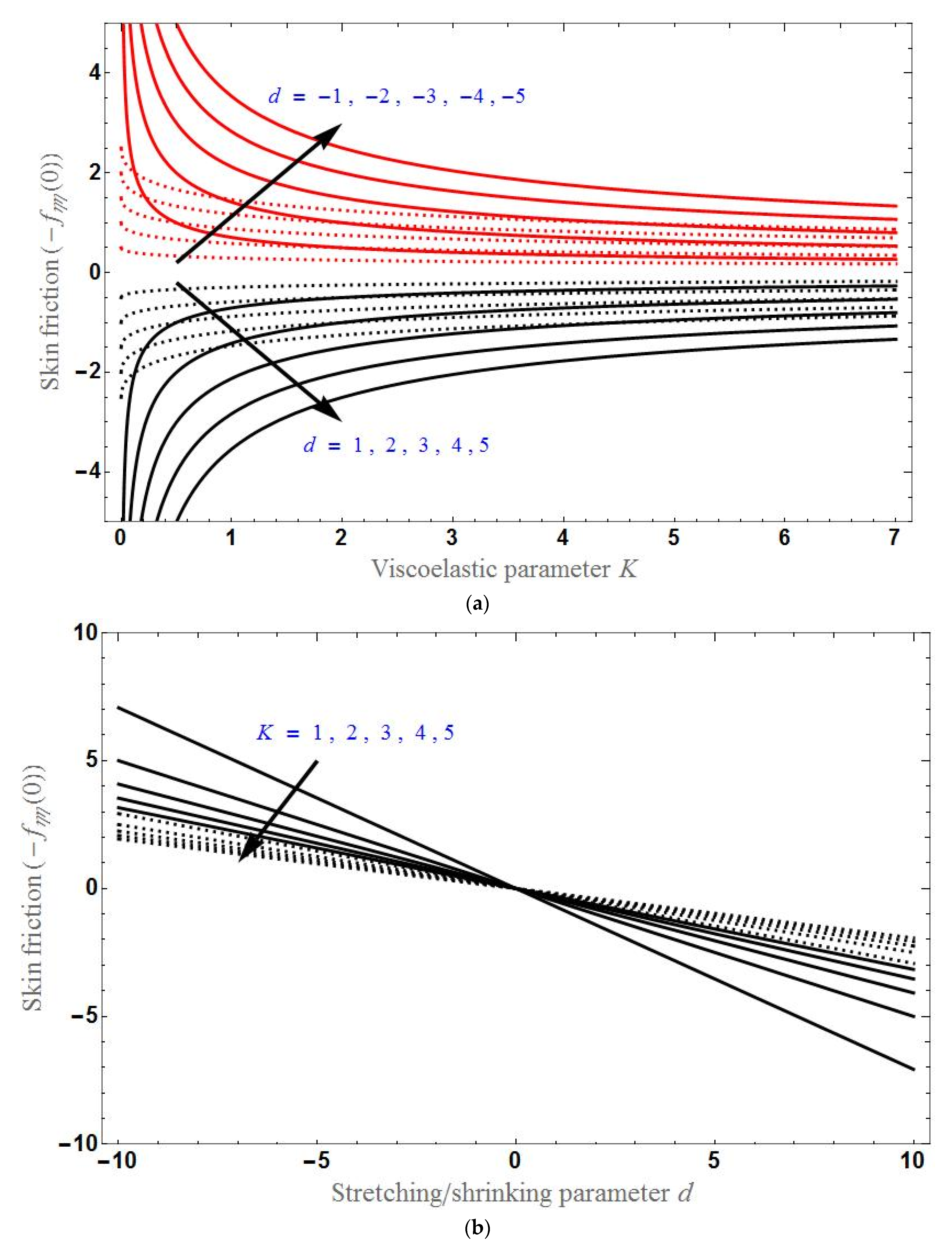
- Skin friction decreases with increases in d and it is greater in the shrinking sheet case than in the stretching sheet case.
- Skin friction increases with increases in K or in the stretching case and will decrease with increases in K or for the shrinking sheet case and become constant after a certain stage.
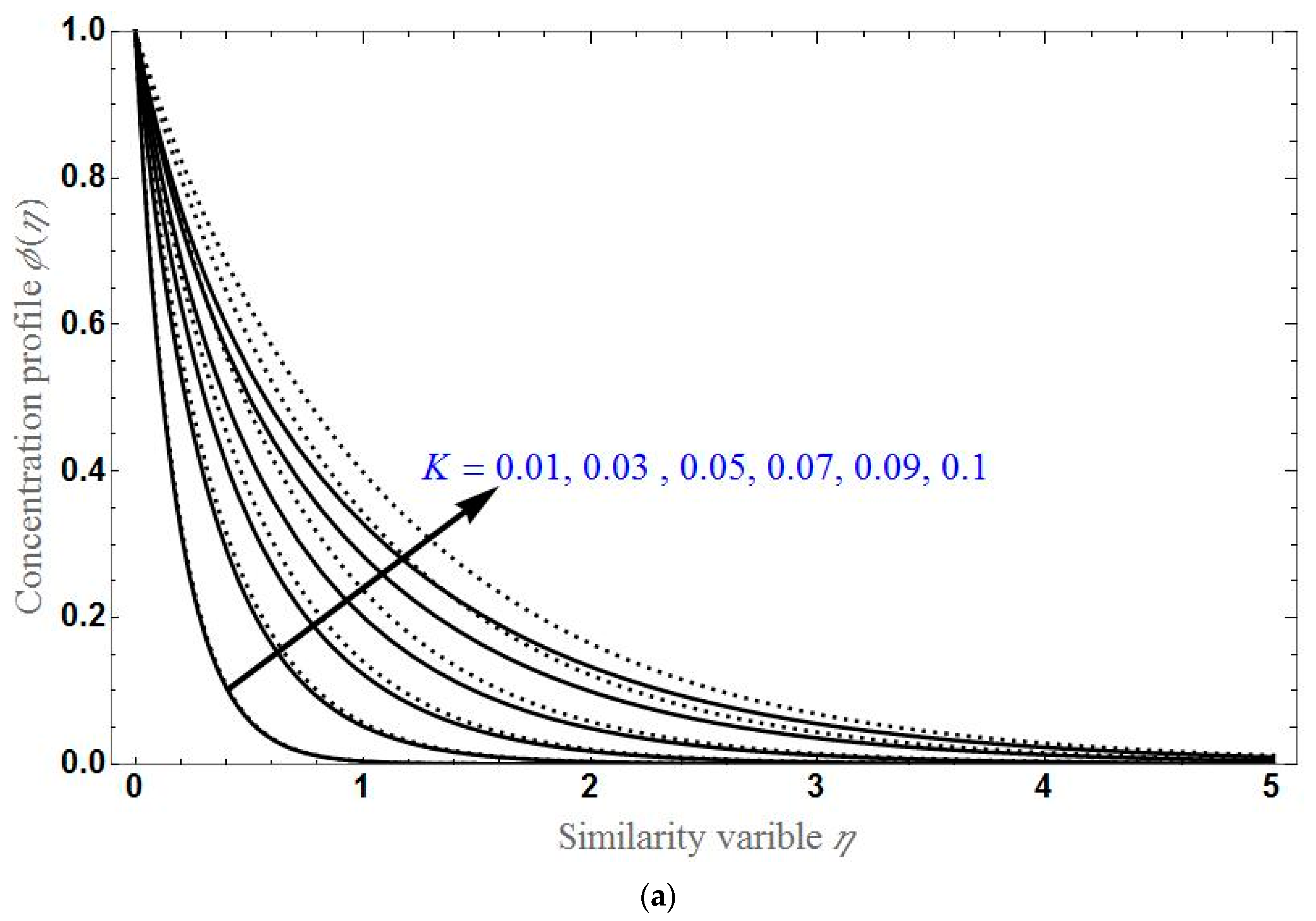
- The concentration profile will be higher for higher values of K or ; it will higher for higher values of in the stretching case and lower for higher values of in the shrinking case.
Author Contributions
Funding
Data Availability Statement
Acknowledgments
Conflicts of Interest
Nomenclature
| Symbol | Description | S.I. Units |
| stretching/shrinking rates | ||
| magnetic field strength | ||
| concentration field | ||
| Stretching/shrinking parameters along x and y axis | ||
| molecular diffusivity | ||
| Inverse Darcy number | ||
| material constant | ||
| viscoelastic parameter | ||
| chemical reaction parameter | ||
| permeability of porous medium | ||
| slip factor | ||
| first order slip parameter | ||
| M | magnetic parameter | |
| Schmidt number | ||
| T | Temperature | |
| Mass transpiration | ||
| velocities along x, y and z direction respectively | ||
| Cartesian coordinates | ||
| wall transpiration | ||
| Greek symbols | ||
| chemical reaction parameter | ||
| Similarity variable | ||
| porosity | ||
| porosity parameter | ||
| dynamic viscosity o | ||
| Kinematic viscosity | ||
| density | ||
| dimensionless concentration | ||
| Electric conductivity | ||
| Brinkman ratio | ||
| Subscripts | ||
| Hybridnanofluid parameter | ||
| Wall condition | ||
| ambient condition | ||
| Abbreviations | ||
| HNF | hybrid nanofluid | |
| MHD | Magneto hydrodynamics | |
| ODEs | Ordinary differential equations | |
| PDEs | Partial differential equations | |
References
- Turkyilmazoglu, M. Magnetic field and slip effects on the flow and heat transfer of stagnation point Jeffrey fluid over deformable surfaces. Z. Für Nat. A 2016, 71, 549–556. [Google Scholar] [CrossRef]
- Turkyilmazoglu, M.; Pop, I. Exact analytical solutions for the flow and heat transfer near the stagnation point on a stretching/shrinking sheet in a Jeffrey fluid. Int. J. Heat Mass Transf. 2013, 57, 82–88. [Google Scholar] [CrossRef]
- Bhattacharyya, K. Dual solutions in boundary layer stagnation-point flow and mass transfer with chemical reaction past a stretching/shrinking sheet. Int. Commun. Heat Mass Transf. 2011, 38, 917–922. [Google Scholar] [CrossRef]
- Akyildiz, F.T.; Bellout, H.; Vajravelu, K. Diffusion of chemically reactive species in a porous medium over a stretching sheet. J. Math. Anal. Appl. 2006, 320, 322–339. [Google Scholar] [CrossRef] [Green Version]
- Mahabaleshwar, U.S.; Vinay Kumar, P.N.; Nagaraju, K.R.; Bognár, G.; Nayakar, S.N. A new exact solution for the flow of a fluid through porous media for a variety of boundary conditions. Fluid 2019, 4, 125. [Google Scholar] [CrossRef] [Green Version]
- Mahabaleshwar, U.S.; Anusha, T.; Sakanaka, P.H.; Bhattacharyya, S. Impact of inclined Lorentz force and Schmidt number on chemically reactive Newtonian fluid flow on a stretchable surface when Stefan blowing and thermal radiation are significant. Arab. J. Sci. Eng. 2021, 46, 12427–12443. [Google Scholar] [CrossRef]
- Sarpkaya, T. Flow of Non-Newtonian Fluids in a Magnetic Field. Am. Inst. Chem. Eng. 1961, 7, 324–328. [Google Scholar] [CrossRef]
- Murthy, P.V.; RamReddy, C.; Chamkha, A.J.; Rashad, A.M. Significance of viscous dissipation and chemical reaction on convective transport in boundary layer stagnation point flow past a stretching/shrinking sheet in a nanofluid. J. Nanofluids 2015, 4, 214–222. [Google Scholar] [CrossRef]
- Miklavcic, M.; Wang, C.Y. Viscous flow due to a shrinking sheet. Q. Appl. Math. 2006, 2, 283–290. [Google Scholar] [CrossRef] [Green Version]
- Mahabaleshwar, U.S.; Lorenzini, G. Combined effect of heat source/sink and stress work on MHD Newtonian fluid flow over a stretching porous sheet. Int. J. Heat Technol. 2017, 35, S330–S335. [Google Scholar] [CrossRef]
- Hayat, T.; Javed, T.; Abbas, Z. Slip flow and heat transfer of a second grade fluid past a stretching sheet through a porous space. Int. J. Heat Mass Transf. 2008, 51, 4528–4534. [Google Scholar] [CrossRef]
- Haq, R.U.; Raza, A.; Algehyne, E.A.; Tlili, I. Dual nature study of convective heat transfer of nanofluid flow over a shrinking surface in a porous medium. Int. Commun. Heat Mass Transf. 2020, 114, 104583. [Google Scholar] [CrossRef]
- Rohni, A.M.; Ahmad, S.; Pop, I.; Merkin, J.H. Unsteady mixed convection boundary-layer flow with suction and temperature slip effects near the stagnation point on a vertical permeable surface embedded in a porous medium. Transp. Porous Media 2012, 92, 1–14. [Google Scholar] [CrossRef]
- Merkin, J.H.; Pop, I.; Rohni, A.M.; Ahmad, S. A further note on the unsteady mixed convection boundary layer in a porous medium with temperature slip: An exact solution. Transp. Porous Media 2012, 95, 373–375. [Google Scholar] [CrossRef]
- Siddheshwar, P.G.; Mahabaleshwar, U.S. Effects of radiation and heat source on MHD flow of a viscoelastic liquid and heat transfer over a stretching sheet. Int. J. Non-Linear Mech. 2005, 40, 807–820. [Google Scholar] [CrossRef] [Green Version]
- Turkyilmazoglu, M. Multiple analytic solutions of heat and mass transfer of magnetohydrodynamic slip flow for two types of viscoelastic fluids over a stretching surface. J. Heat Transf. 2012, 134, 071701. [Google Scholar] [CrossRef]
- Khan, S.K.; Abel, M.S.; Sonth, R.M. Visco-elastic MHD flow, heat and mass transfer over a porous stretching sheet with dissipation of energy and stress work. Heat Mass Transf. 2003, 40, 47–57. [Google Scholar] [CrossRef]
- Sakiadis, B.C. Boundary layer behavior on continuous solid surface. Am. Inst. Chem. Eng. 1961, 7, 26. [Google Scholar] [CrossRef]
- Crane, L. Flow past a stretching plate. Zeitschift Ange-Wandte Math. Phys. 1970, 21, 645–647. [Google Scholar] [CrossRef]
- Ghasemi, E.; Bayat, M.; Bayat, M. Viscoelastic MHD flow of Walters liquid B fluid and heat transfer over a non-isothermal stretching sheet. Int. J. Phys. Sci. 2011, 6, 5022–5039. [Google Scholar]
- Turkyilmazoglu, M. Three dimensional MHD flow and heat transfer over a stretching/shrinking surface in a viscoelastic fluid with various physical effects. Int. J. Heat Mass Transf. 2014, 78, 150–155. [Google Scholar] [CrossRef]
- Hamid, M.; Usman, M.; Khan, Z.H.; Ahmad, R.; Wang, W. Dual solutions and stability analysis of flow and heat transfer of Casson fluid over a stretching sheet. Phys. Lett. A 2019, 383, 2400–2408. [Google Scholar] [CrossRef]


Publisher’s Note: MDPI stays neutral with regard to jurisdictional claims in published maps and institutional affiliations. |
© 2022 by the authors. Licensee MDPI, Basel, Switzerland. This article is an open access article distributed under the terms and conditions of the Creative Commons Attribution (CC BY) license (https://creativecommons.org/licenses/by/4.0/).
Share and Cite
Mahabaleshwar, U.S.; Anusha, T.; Laroze, D.; Said, N.M.; Sharifpur, M. An MHD Flow of Non-Newtonian Fluid Due to a Porous Stretching/Shrinking Sheet with Mass Transfer. Sustainability 2022, 14, 7020. https://doi.org/10.3390/su14127020
Mahabaleshwar US, Anusha T, Laroze D, Said NM, Sharifpur M. An MHD Flow of Non-Newtonian Fluid Due to a Porous Stretching/Shrinking Sheet with Mass Transfer. Sustainability. 2022; 14(12):7020. https://doi.org/10.3390/su14127020
Chicago/Turabian StyleMahabaleshwar, Ulavathi Shettar, Thippeswamy Anusha, David Laroze, Nejla Mahjoub Said, and Mohsen Sharifpur. 2022. "An MHD Flow of Non-Newtonian Fluid Due to a Porous Stretching/Shrinking Sheet with Mass Transfer" Sustainability 14, no. 12: 7020. https://doi.org/10.3390/su14127020
APA StyleMahabaleshwar, U. S., Anusha, T., Laroze, D., Said, N. M., & Sharifpur, M. (2022). An MHD Flow of Non-Newtonian Fluid Due to a Porous Stretching/Shrinking Sheet with Mass Transfer. Sustainability, 14(12), 7020. https://doi.org/10.3390/su14127020