Article

Zero Non-Detection Zone for Islanding Detection Based on a Novel Hybrid Passive-Active Technique with Fuzzy Inference System

1
Electrical Engineering Department, Egyptian Academy for Engineering and Advanced Technology (EAE&AT), Affiliated to the Ministry of Military Production, Cairo 32511, Egypt
2
Industrial Electronics and Control Engineering Department, Menofia University, Menouf 32511, Egypt
3
Electrical Engineering Department, Kwame Nkrumah University of Science and Technology, Kumasi 23321, Ghana
4
Ministry of Electricity, Sector of Electricity Market and Cross-Border Interconnection at (EEHC) Cairo, Cairo 11765, Egypt
*
Author to whom correspondence should be addressed.
Sustainability 2022, 14(10), 6325; https://doi.org/10.3390/su14106325
Submission received: 5 February 2022 / Revised: 15 April 2022 / Accepted: 18 April 2022 / Published: 22 May 2022
(This article belongs to the Topic Distributed Generation and Storage in Power Systems)

Abstract

:
Distributed generation (DG) has reformed the meaning of power generation from large scale to small scale, but unintentional islanding is the main issue when connecting DG and the utility grid. A lot of techniques have been used for detecting islanding, among these techniques, there are passive and active. The main problem of passive techniques is their large non-detection zone (NDZ), while the main drawback of active techniques is their undesirable effect on power quality. In this paper, a proposed hybrid passive–active systematic methodology based on a smart classifier that decides to use an active method instead of a passive one is presented. In the proposed scheme, sensors are used for measuring the reactive power at three terminals: the DG terminal, grid terminal, and load terminal. The novelty in this paper is the accurate detection of islanding within a shorter time either in the normal case or NDZ; also it can differentiate between islanding and grid faults without degrading the power quality of the overall system as the active technique does not have to be used continuously, and so total harmonic distortion does not exceed the standard value (5%) detected by IEEE standards. The proposed scheme was simulated using the MATLAB/Simulink platform, and the results reflect its potential with a comparative study.

1. Introduction

In the world of rapid progress, electric distribution technology has shown a massive growth in the last few years. The modifications on both the demand and supply side are needed. The higher energy availability and efficiency are desired and the integration of distributed generation (DG) as well as good control technologies are required from demand and supply side respectively [1].
In general, DGs technologies have good overall efficiencies. Besides, renewable energy based DG units contribute in reducing greenhouse gases. DGs are connected in distribution systems close to load centers to provide many benefits to the customers, utilities and environment [1,2]. But on the other hand, negative impacts occur especially on the distribution system’s protection scheme due to the fact that the integration of DGs in distribution systems will deteriorate the radial nature of these systems. In addition, there will be an increasing in the short circuit levels of the network [3], miss-coordination between the protective devices [4], false tripping of the protective devices [5], protection system blinding and islanding. As a brief explanation for islanding phenomenon; by the grid outage, a part of load is still fed through DGs.
Islanding can be classified into intentional and unintentional islanding. Intentional islanding occurs when the DG unit works as a backup to network outage to increase the reliability like UPS. But unintentional islanding is a situation of feeding a part of load through DG or group of DGs, while outage of network occurs [6].
Hence, unintentional islanding is a concern primarily because it poses a hazard to utility and customer equipment, maintenance personnel and the general public. As more DG systems become part of the power grid, there is an increased safety hazard for personnel and an increased risk of damage to the power system. Despite the favorable aspects grid-connected DGs can provide to the distribution system, a critical demanding concern is islanding detection and prevention. Failure to trip islanded DG can lead to a number of problems for these resources and the connected loads, which includes power quality, safety and operation problems. Therefore, the current industry practice is to disconnect all distributed resources (DRs) immediately after the occurrence of islands [1,2]. The disconnection is normally performed by a special protection scheme called islanding detection relays, which can be implemented using different techniques. However, during the design process of the islanding detection scheme, the detection of islanding conditions according to international standards [3,4,5,6], must be also considered [3].
Different techniques are discussed in the literature for detecting the islanding case. These techniques are generally classified into local and remote techniques [5]. The remote techniques use the advanced signal processing methods and communication infrastructure that are utilized for islanding detection. Remote techniques have no NDZ and have high reliability in comparison with local islanding detection techniques [5]. Their performance is independent of the type of DG units involved [4,5]. On the other hand, local techniques can be categorized into passive, active, and hybrid schemes [7]. Passive techniques decide based on the local measurements and predefined thresholds without any changes in microgrid [8]. In [9] islanding is detected using the measurement of harmonic distortion. Another way is presented in [10] by using the displacement of the phase angle and the voltage surge. In [11], the authors used the frequency and voltage abnormalities values to identify the islanding incidence. All these passive techniques cannot detect islanding in NDZ but they can detect islanding in a a small time.
Active techniques inject perturbations to micogrids to decide based on the consequent changes in local measurements they depend on disturbing the signals by injecting some disturbances into the system [11]. Additionally, signal processing approaches and artificial intelligence techniques are used. Fast Fourier transform (FFT) [12,13] depend only on a frequency spectrum and are unable to catch islanding due to the instability features in the current, power, and voltage waveforms. Therefore, time-frequency was proposed to observe non-stationary disturbances, but it also failed to catch islanding in some cases [14] owing to its non-adaptive window size. In [15], a machine learning algorithm was joined with wavelet transform (WT) to notice the islanding incident and this mixture gave high adaptability and more accuracy but it has a complexity in learning the rules. The output of WT was used in [16] as input for neuro-fuzzy and this combination had many merits as simplicity and fast but not accuracy. In [17] a combination of a support vector machines (SVMs) algorithm and WT with s-transform improves the performance and minimizes noise but it cannot detect islanding in NDZ [18].
A hybrid technique of WT with fuzzy in [19] is accomplished by a successful performance under various conditions. All the methods based on wavelet transform depend on a selected signal for detection which has a great challenge as if the threshold of this signal is very small, false tripping may happen and if it is high, the detection may not occur. In [20], they solve the problem of signal threshold selection by applying the neuro-fuzzy algorithm on multiple distributed generation microgrid (MG) and are able to catch the islanding, but it has a drawback in the case of disconnection of a single DG. A hybrid technique between an artificial neural network and Fourier transform is presented in [21] to detect islanding on the wind turbine but is more complex in construction. A lot of artificial intelligence techniques are used to catch islanding such found in [22,23,24,25,26,27].
From the previous work, The mixture between passive and active with a fuzzy classifier is not presented before. In this paper a novel anti-islanding detection technique is used to get zero NDZ and accurate islanding detection without degrading the power quality, and the results are verified by Matlab/Simulink. As the presented proposed technique is a hybrid between active and passive techniques, its results are compared with the results of a hybrid between two passive techniques in [28], and a hybrid between active and passive techniques in [29]. As in [28], islanding is detected using a combination of the rate of change of power with terminal voltage to get fast and accurate detection of the islanding phenomenon under any load variation except equality between the power generated and the load. However, in [29] a combination of the rate of change of voltage and rate of change of active power has been used for the islanding detection process in a wide range of scenarios.
The main contributions of the work are finding zero NDZ, keep the power quality of the system, overcoming the problem of determining the appropriate thresholds and the proposed technique not only detects islanding but also differentiates between it and grid faults.
The rest of the paper is structured in four sections. Section 2 presents the definition of the non-detection zone. Section 3 presents the proposed technique and its flowchart. The simulation results of islanding conditions that are detected by the proposed technique using MATLAB/SIMULINK are presented in Section 4. A comparison between the proposed technique and the other techniques in [28,29] is presented in Section 5. Finally, in Section 6, the conclusions are summarized.

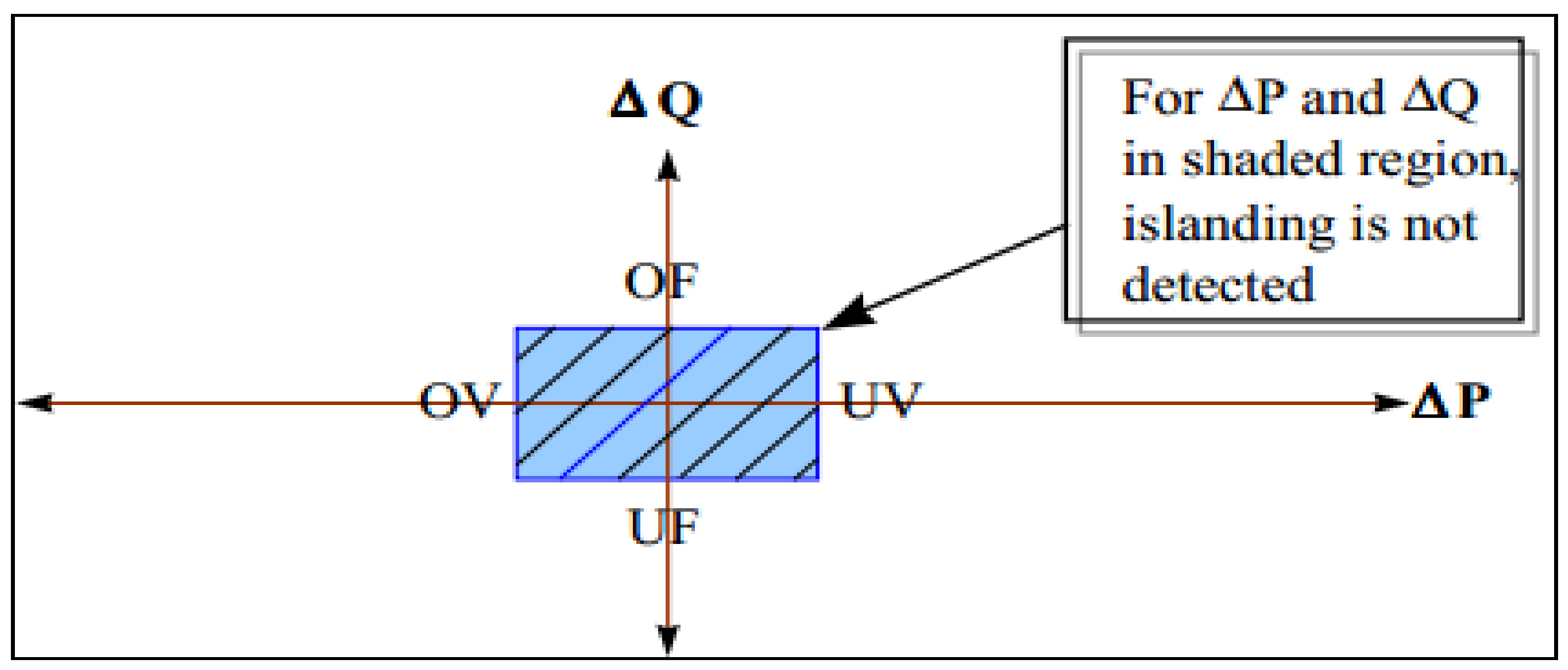
2. Non-Detection Zone (NDZ)

The area where the mismatch percentage is small to reach a specific level islanding is not detectable by passive methods is called None Detection Zone (NDZ). The NDZ limits are defined according to particular values of voltage’s amplitude and frequency which are considered as the maximum/minimum allowable limits that voltage’s amplitude and frequency should not exceed. The passive islanding detection methods are known to be inefficient in the NDZ. The power flow between the utility grid and DG source is shown in Figure 1.
The NDZ, represented by the shaded region in Figure 2, can also be defined as the area where there is a power mismatch between the utility grid and DG source that is established by a coordinate system using an active power mismatch axis and a reactive power mismatch axis (ΔP and ΔQ), that are declared in Equations (1) and (2) [2]:
Δ P   =   P D G     P L O A D  
  Δ Q   =   Q D G     Q L O A D  
P D G   and   Q D G   are the DG source real and reactive power, respectively. Similarly,   P L O A D   and   Q L O A D are loads of real and reactive powers, their threshold limits are determined by Equations (3) and (4) [2].
V V m a x 2     1       Δ P P     V V m i n 2     1  
1     f f m i n 2     Δ Q P     1     f f m a x 2  
( V m a x ,   f m a x ,   V m i n   and   f m i n ) are the maximum (voltage, frequency) and the minimum (voltage, frequency), respectively, calculated at the PCC, and their values are detected according to the IEEE 1547 series standard are shown in Table 1.
The load reactive power can be illustrated by Equation (5) [29].
Q L O A D   =   3 v 2 ( 1 w n L     w n C )  
where w n ,   L ,   C   and   v   are the nominal frequency load, inductance, capacitance, and voltage, respectively. By taking into account the unity power factor, so the reactive power mismatch is equal to the load reactive power [29] which can be calculated using (6):
Δ Q   =   3 v 2 w n L ( 1     w n 2 L C )   =   3 v 2 w n L 1     w n 2 w r 2    
where w r is the load resonance frequency.
w r   =   w n   ±   w
Therefore, the reactive power mismatch for NDZ calculation can be written as follows [29]:
Δ Q   =   3 v 2 w n L 1     f n 2 ( f n   ±   Δ f ) 2
where w r ,   Δ f are the resonance frequency and permissible frequency range, respectively.
On the other hand, Δ P is declared by Equation (1) [2] and the load active power can be illustrated by Equation (9) [29].
P L O A D   =   3 v 2 R 1
The active power mismatch is the difference between the active power attracted by local load resistance as R 1 which causes deviation as Δ V in voltage [29].
Δ P   =   3 v 2 R 1 1 1   ±   Δ V 2     1

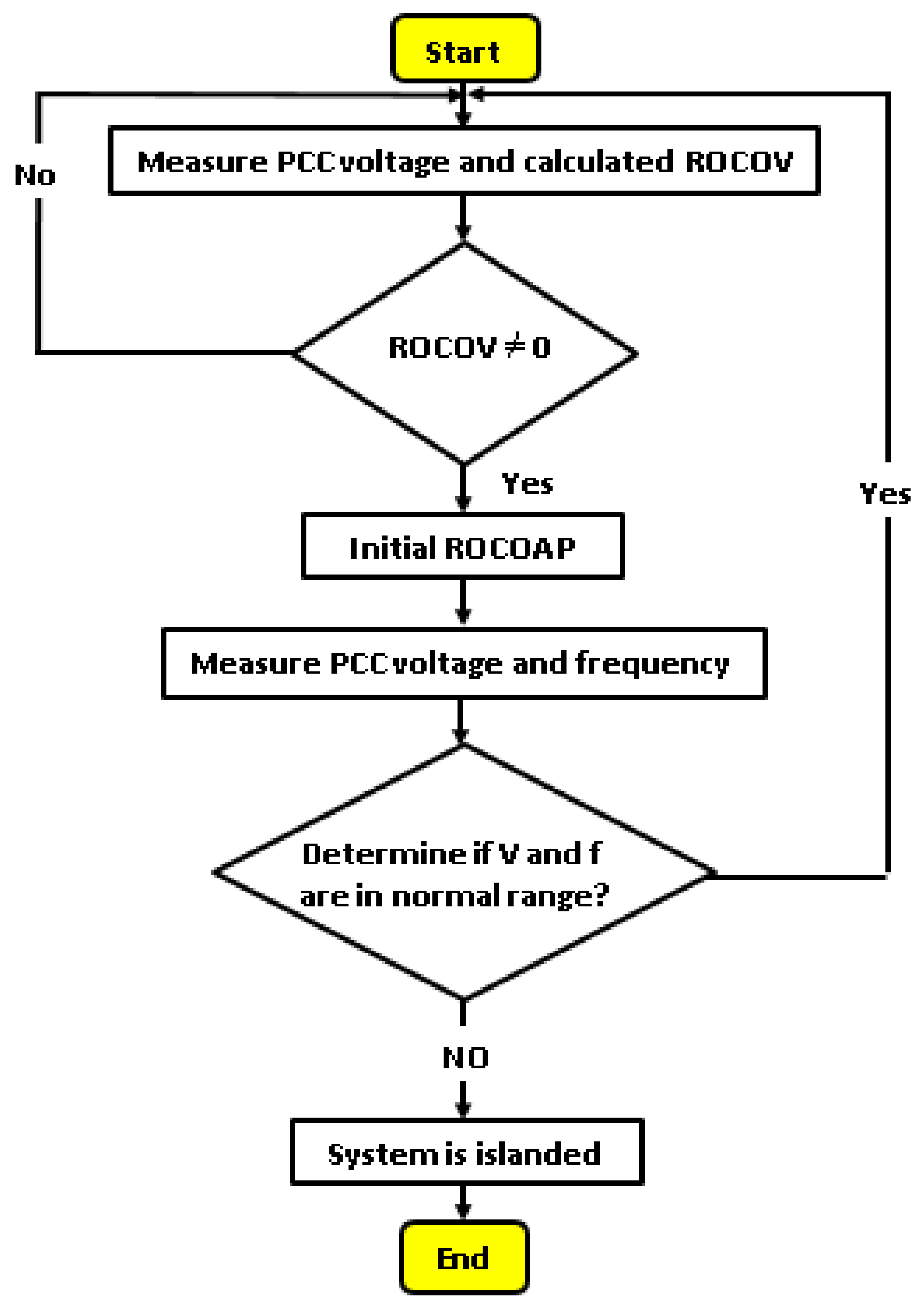
3. Proposed Technique and Its Flowchart
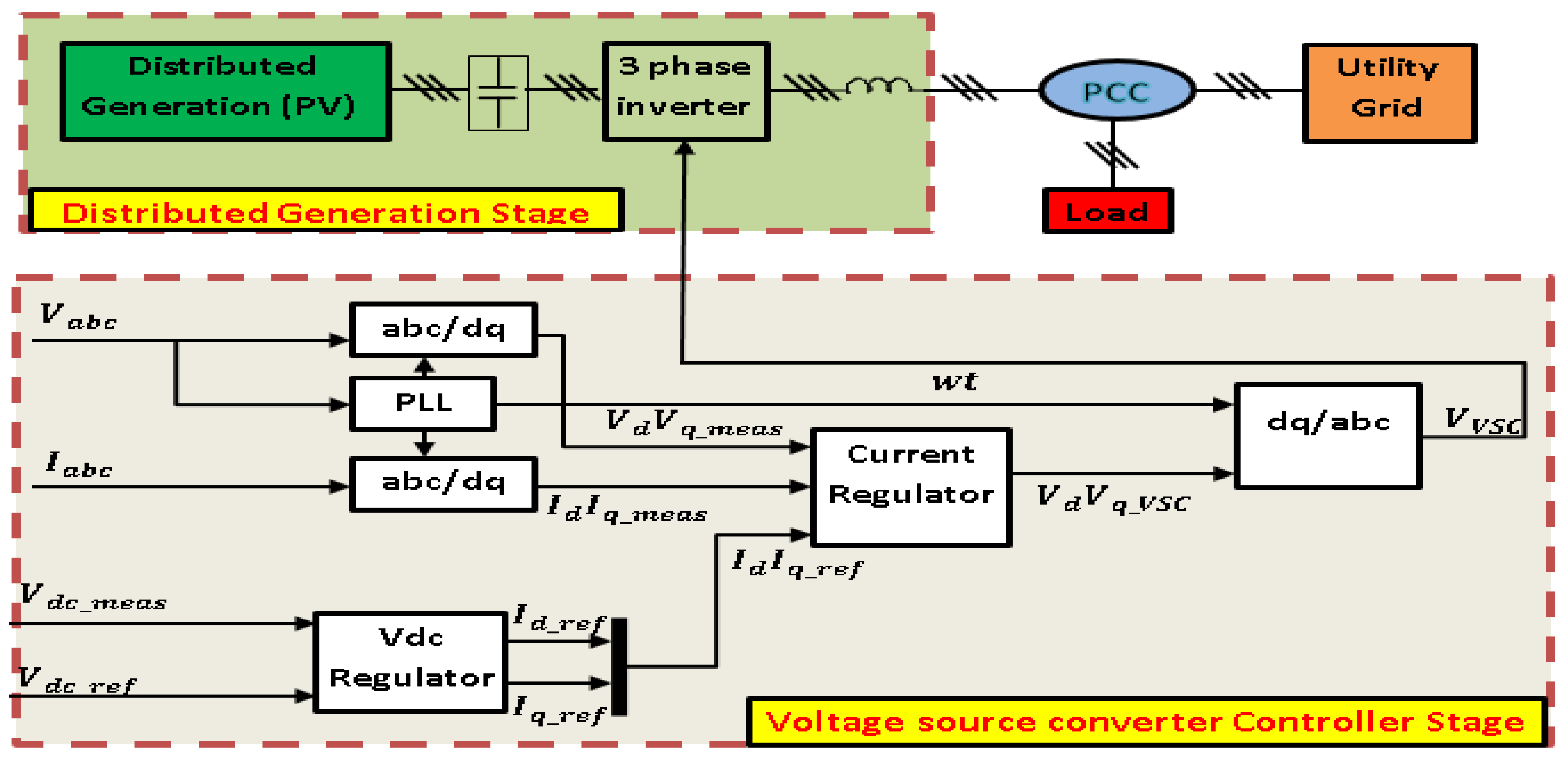
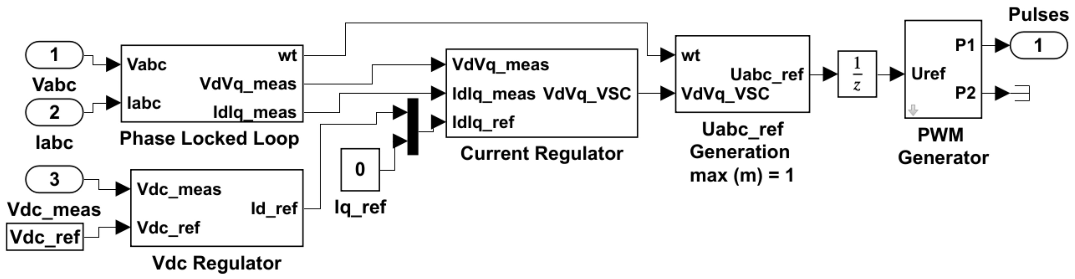
The concept of the proposed technique depends mainly on the voltage source converter (VSC) controller and will be described in the following paragraph.

3.1. VSC Controller

The three-level VSC that is declared in Figure 3 and its Simulink implementation depicted in Figure 4 [2] regulates the dc bus voltage at 600 V and keeps the unity power factor.
The VSC controller presented in Figure 4 shows the controller system that uses two control loops: an external control loop that regulates the reference of dc-link voltage ( V d c     r e f ) to 600 V and an internal control loop that regulates id and iq grid currents (active and reactive current components). The id current reference ( i d r e f ) is the output of the dc voltage regulator. The iq current reference ( i q r e f ) is set to zero to maintain the unity power factor. The voltage outputs of the current controller ( v d   &   v q ) are converted to three modulating signals ( V v s c ) used by the pulse-width modulation (PWM) three-level pulse generator.
So the active and reactive power of the PV grid converter in a dq frame is given by Equations (11) and (12) [24]:
P   =   3 / 2   ( V d i d   +   V q i q )
Q   =   3 / 2   ( V d i d     V q i q )
i d r e f is the desired active output power control, while i q r e f is the desired reactive output power, and is also used to achieve unity power factor operation, in which the grid current vector is in phase with the grid voltage vector, thus i q r e f should be zero. Aligning the d axis with the grid voltage, then the active power and the reactive power can be expressed by [24]:
P   =   3 / 2   ( V d i d )
Q   =   3 / 2   ( V d i q )
Equations (13) and (14) indicate that P is proportional to i d and can therefore be controlled by it. Similarly, the reactive power Q is regulated by controlling i q . So the proposed technique can control islanding by making a variation in i q that will lead to a variation in reactive power hence the reactive power will be the main parameter for detecting islanding.

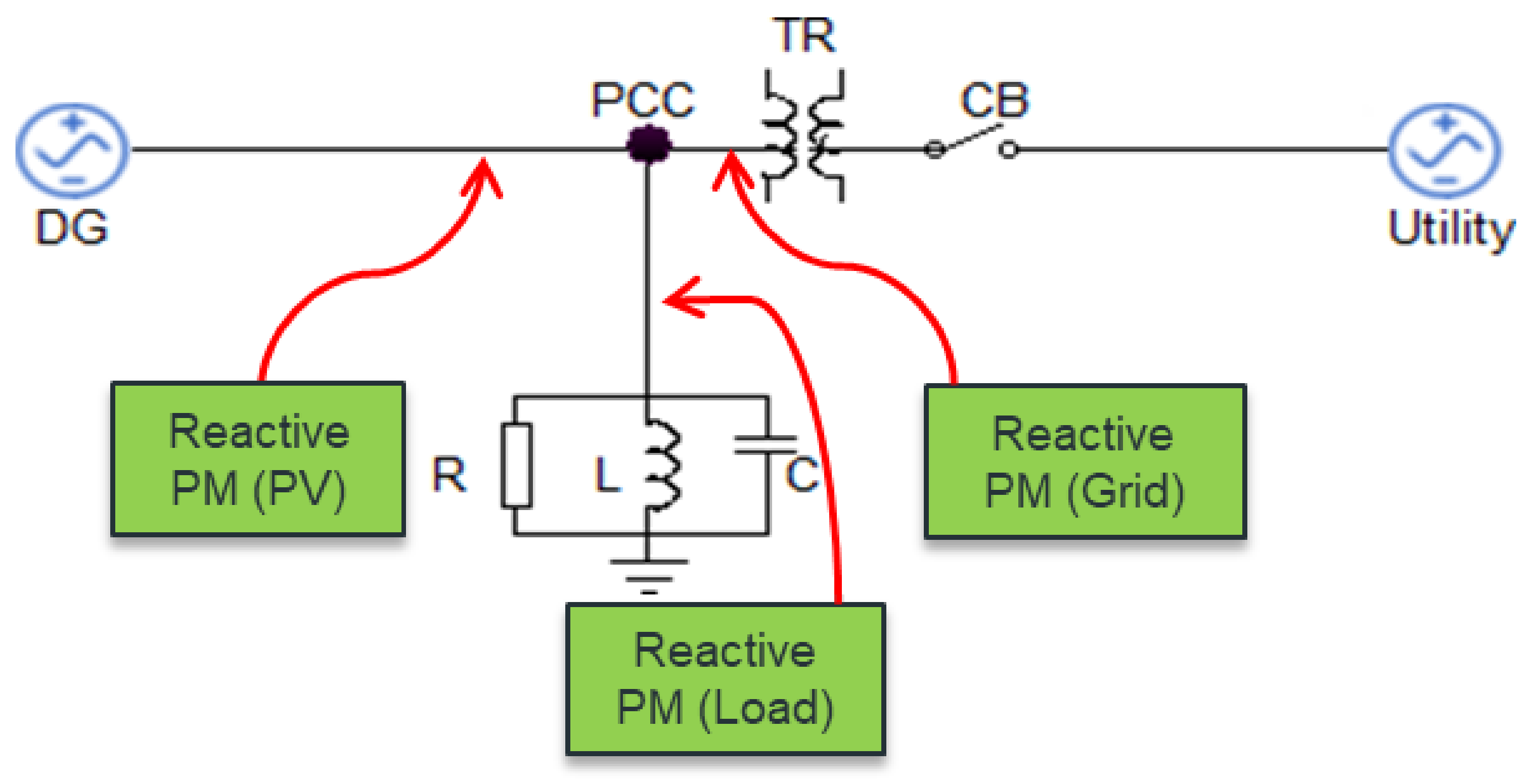
3.2. The Proposed Technique Theory

From all the anti-islanding detection techniques mentioned in Section 1, we conclude that the passive techniques are the simplest and cheapest but it has large NDZ, on the other hand, active techniques have a small NDZ but degrade power quality and insert disturbances during the grid-connected operation. The proposed method aims to detect islanding accurately even in NDZ, reduce the injection of disturbances, and overcome the problem of determining the appropriate thresholds using a fuzzy classifier system. The proposed technique measures the reactive power of PV ( Q P v ) , load ( Q l o a d ) , and grid ( Q G r i d ) using a power meter (PM) as depicted in Figure 5, and the flowchart of the proposed technique is presented in Figure 6. These three values of reactive power are the inputs to the fuzzy system to make a decision, for example, if the value of reactive power of the grid is small and the other two values are not small, that means there is no connection between the DG and utility grid then synchronization is checked, if it is active and has reached steady state (SS), then islanding is detected. However, if the value of reactive power of the grid is not small, in this case, it means that there is a connection between DG and grid, and hence no islanding is detected. In the case of a small value of the three meters, the order for disturb is generated and applies a change to the iq of the inverter by varying the power factor to be 0.95 at minimum to guarantee that the power quality of the system at PCC is not affected. This change in iq will affect the reactive power of PV by a small variation if there is not any change in the reactive power of the grid, and synchronization is still active, hence islanding is detected, but if there is a change that means there is no islanding and it repeats the measurements. THD is an indication to ensure that the effect of variation in iq is within 5% according to standards [2] and it is measured by Equation (15).
T H D   =   h = 2 H I h 2 I 1   ×   100
I h is the RMS value of the h th harmonic component of the current and I 1 is the RMS value of the fundamental component of current.

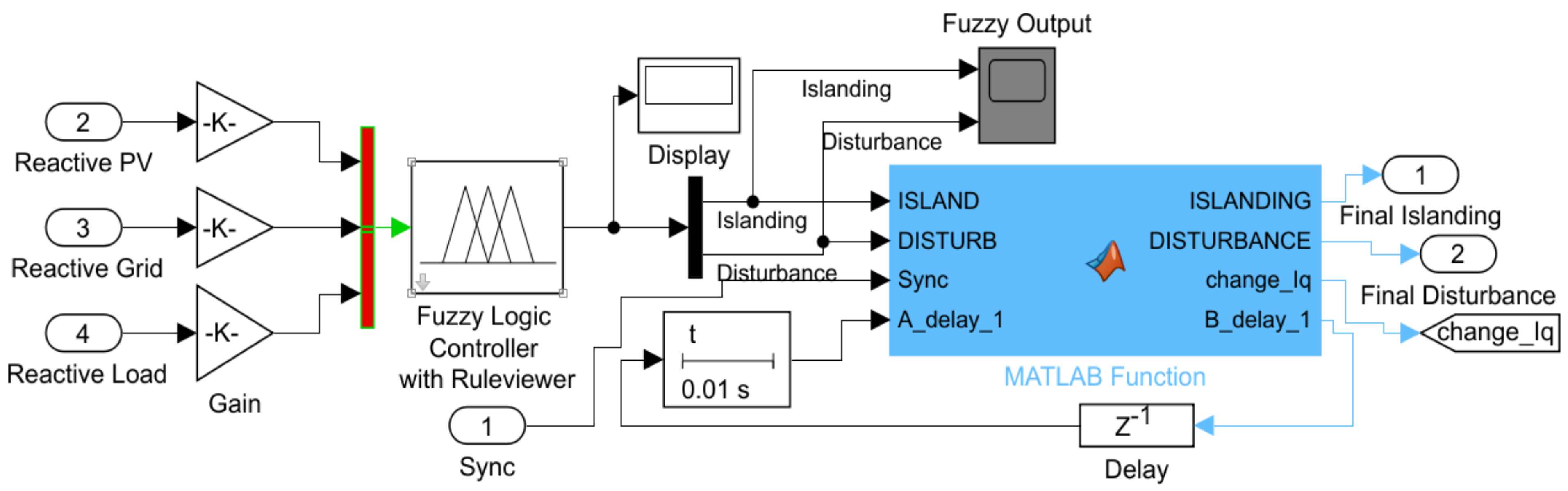
3.3. Fuzzy Inference System

According to the frequent parameter variations of the studied system, the fuzzy classifier is more effective compared to the crisp classifier. As shown in Figure 7, three reactive power measurements of PV, load, and grid are entering the fuzzy system as inputs, and the outputs are island and disturb. If the fuzzy output is an island, then it checks the synchronization between grid and DG if yes then the islanding decision is energized. However, if the fuzzy output is disturb, then it enters the Matlab function to make the change in the iq of the inverter in a way that is not less than a 0.95 power factor, then the three reactive values are checked again to get the final decision if islanding or it repeats the sequence of disturbance after guaranteeing the synchronization between grid and DG. So the fuzzy rules are in the form of (if, then rule) and are represented in Table 2 as follows:

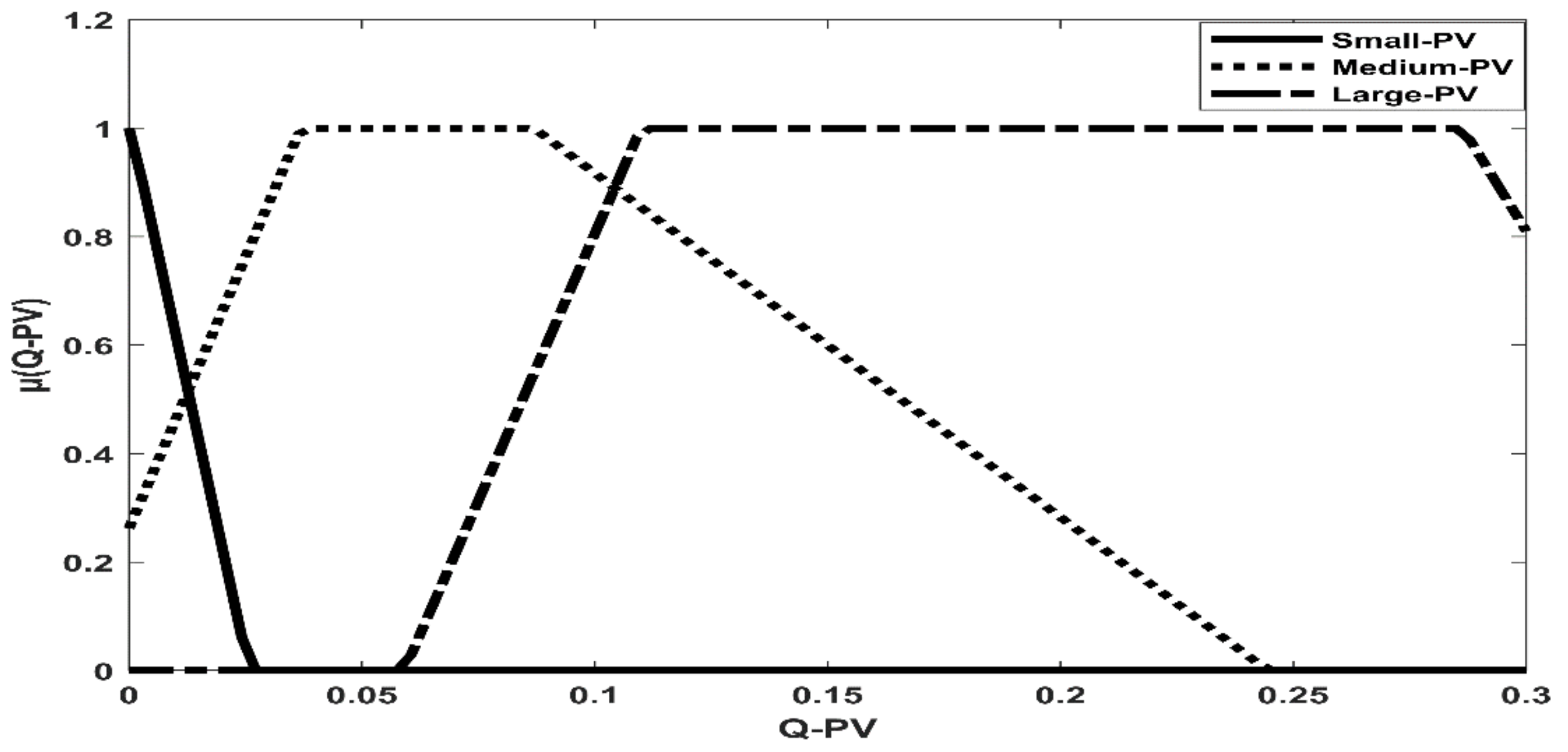
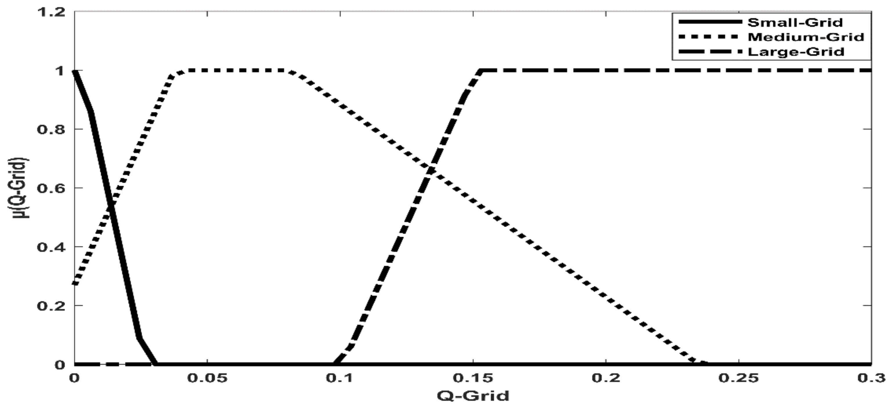
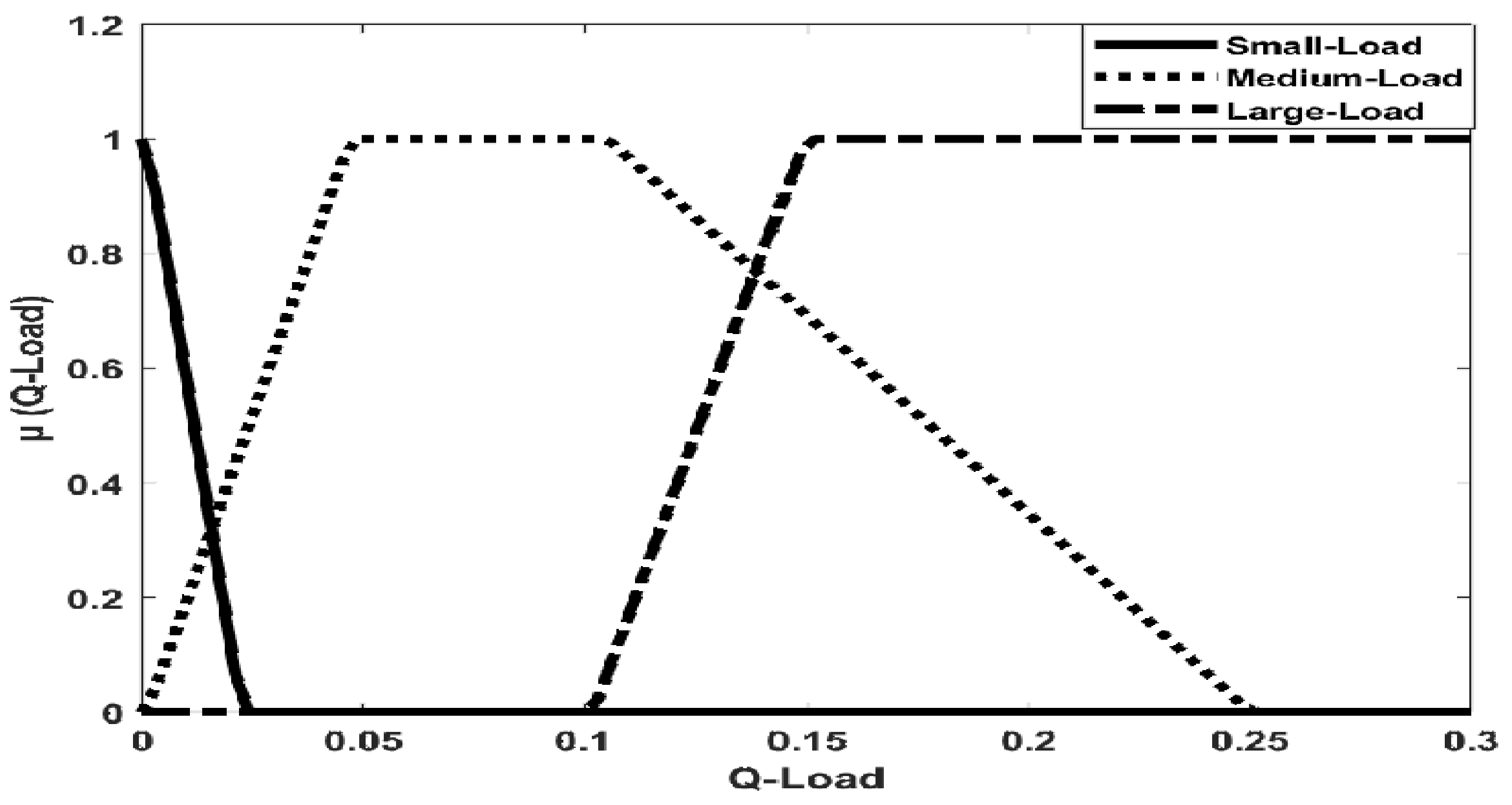
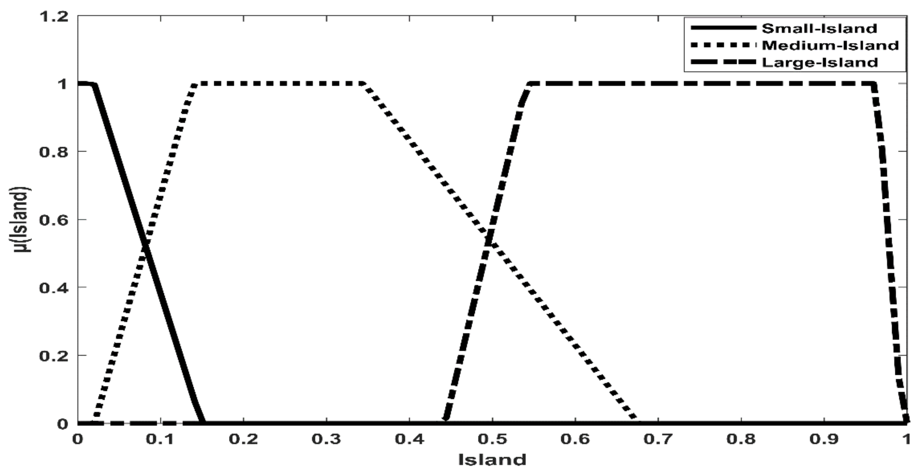
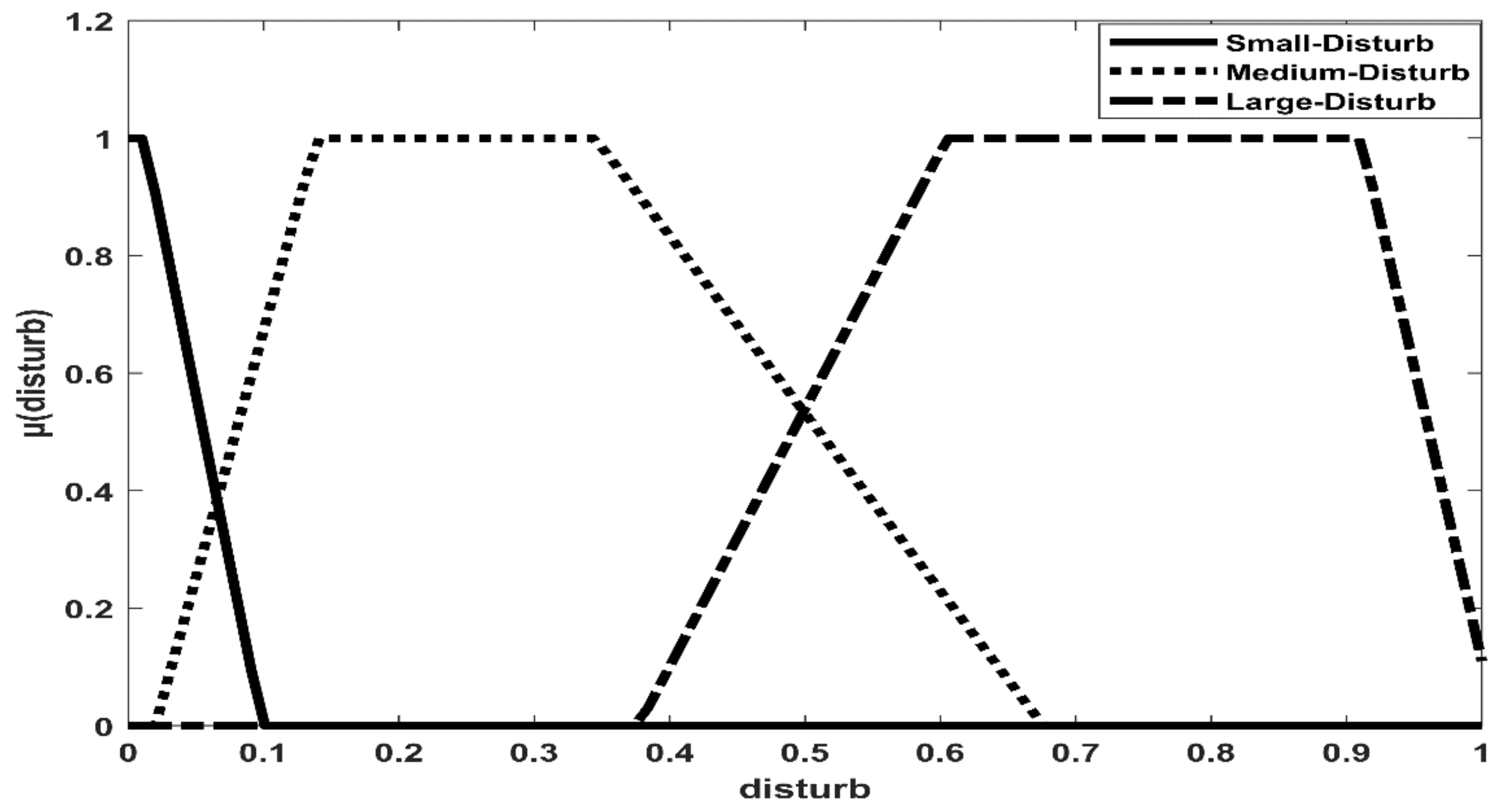
3.4. Membership Function Formulation

There are many different choices of membership functions, and after trying, the trapezoidal membership function is the most effective compared to the triangular and Gaussian ones. Reactive powers of PV, grid, and load are taken to be the fuzzy inputs (X1, X2, and X3), but island and disturb are the fuzzy outputs (Q1 and Q2). The following Figure 8, Figure 9, Figure 10, Figure 11 and Figure 12 are the membership functions for the monitored parameters inputs and outputs.

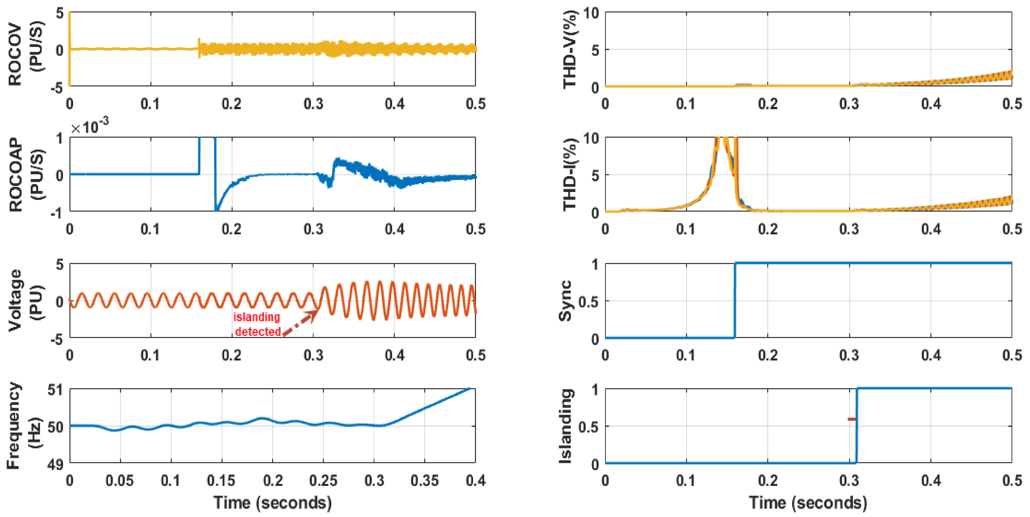
4. The Matlab Implementation Results of Hybrid Passive-Active Technique with a Fuzzy Smart Scheme

The proposed technique is applied to the model presented in [28]. All figures of the results (Figures 13–24 and 27–32) consist of three columns with colored lines as, the three input signals of the fuzzy system (Q-PV, Q-load, Q-grid) and the three phase total harmonic distortion of voltage (THD-V) are presented in the first column. Active powers (P-PV, P-load, P-grid) and the three phase THD of current (THD-I) are presented in the second column, the third column consists of the synchronization signal between DG and grid, the variation signal for the inverter (iq), and the two outputs of the fuzzy system: disturb and island. The results are classified into two types: by applying varying load and grid faults, as presented below:

4.1. Simulation Results of Different Values of Load for Islanding Phenomenon

4.1.1. Power Mismatch between DG and Load (Normal Case)

Figure 13 presents the simulation result of applying islanding at 0.3 s after disconnection of the circuit breaker in case of a load that consumes 25 kW, 10 kVAr. So in this figure, the Q-grid starts to supply the Q-load until the synchronization becomes active then it continues supplying the Q-load and it is found that the Q-PV is still zero as iq equals zero. This will last until islanding occurs, then the value of the Q-grid decreases to zero, and the Q-PV starts increasing to substitute the value of the Q-load. In this case, the decision of fuzzy is to generate the islanding detection signal and be sure that the synchronization signal between grid and DG is active, and then islanding is detected. In this situation, there is no variation in iq and hence no disturb signal, and so the THD-I and THD-V of the system do not reach 5% in the zone of the detection according to IEEE standards hence there is no effect on the power quality of the system. Figure 13 also presents the relationship between the active powers as the P-grid starts to supply the P-load until the synchronization becomes active then the P-PV switches to supply the P-load instead of the P-grid and the remaining power went to the grid, which will last until islanding occurs, then the value of P-grid decrease to zero and the whole P-PV went to load.

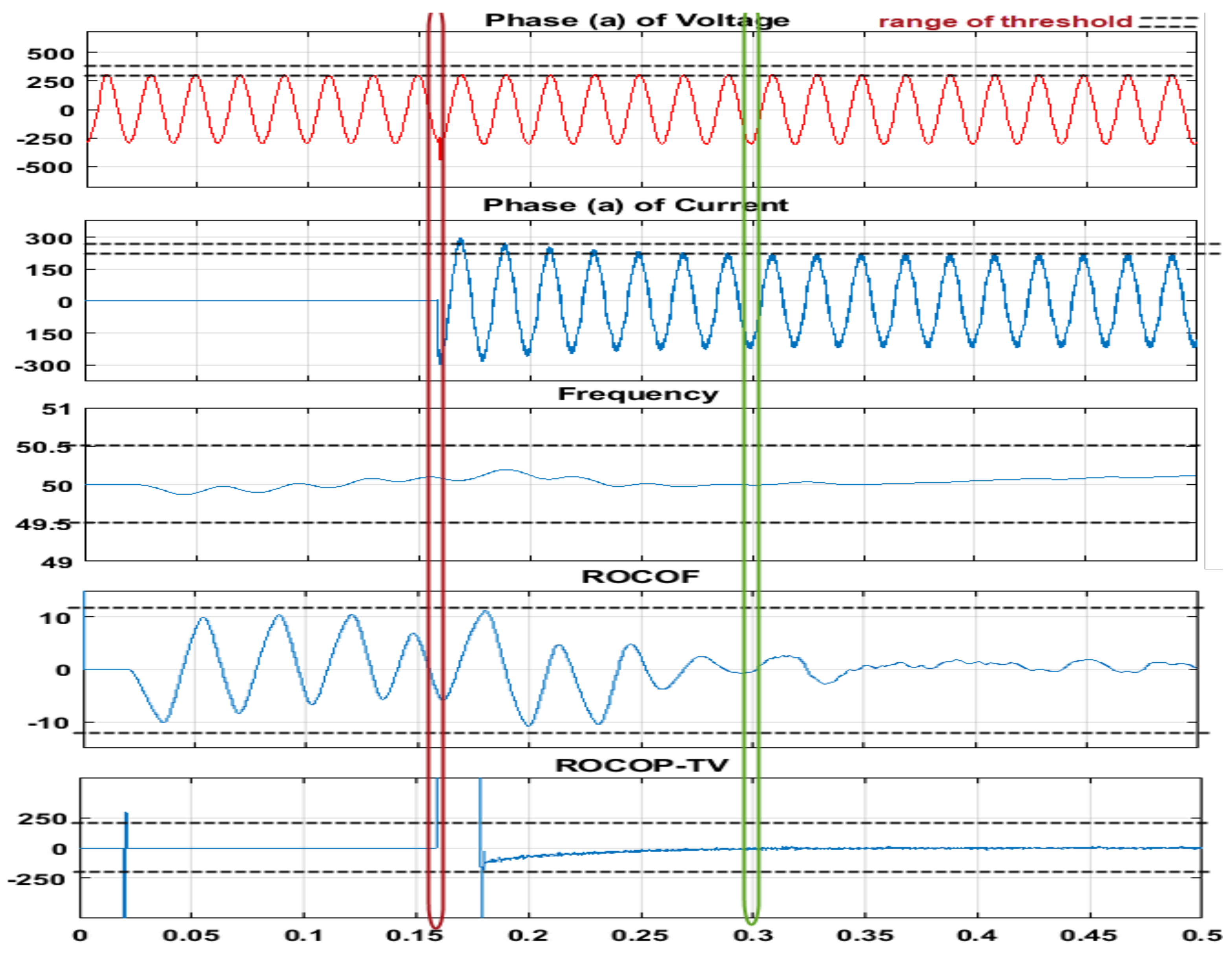
4.1.2. Power Match between DG and Load (NDZ Case)

In the case of NDZ in Figure 14, the load consumes 100 kW, 0 kVAr, after disconnection, it is found that the value of Q-PV equals Q-grid which means the active technique must be used so the fuzzy generates the disturbance signal and repeats the measurements. If the status of disturb is held active for 0.01 s, iq will be changed according to the change of power factor to be 0.95 instead of 1. THD is an indication to ensure that the effect of variation in iq is within 5% according to standards [3]. If this variation affects the Q-grid and the synchronization signal is still active that means there is no islanding, but if there is no variation in the Q-grid, islanding will be detected. If the synchronization is failed for any reason islanding cannot be detected.
Figure 14 also presents the relation between the active powers as the P-grid starts to supply the P-load until the synchronization becomes active, then the P-PV switches to supply the P-load instead of the P-grid that will last without any change after islanding occurrence so active power cannot be assumed to be a good parameter to detect islanding in case of NDZ.

4.2. Simulation Results of Different Types of Faults Impact

Faults are applied to clarify the accuracy of the proposed technique by observing the behavior of each fault. For example, a single-phase fault applied at 0.3 s for a load that nearly consumes 25 kW, 10 kVAr, and its performance is presented in Figure 15, the Q-grid starts to supply the Q-load until the synchronization becomes active. Then it continues supplying the Q-load and it is found that Q-PV is still zero as iq equals zero, which will last until a fault occurs. In this case, there is a disconnection in the synchronization signal between grid and DG due to the fault, so fuzzy did not generate the islanding detection signal. As there is no variation in iq and hence no disturb signal, as a result of that the THD-I and THD-V of the system do not reach 5% and hence there is no effect on the power quality of the system. Figure 15 also presents the relationship between the active powers as the P-grid starts to supply the P-load until the synchronization becomes active then the P-PV switches to supply the P-load instead of the P-grid and the remaining power went to the grid, which will last until a fault occurs. That will last until a fault occurs, then the value of P-PV decreases to zero, and the grid return to supply the P-load. The other faults such as a double-phase fault, double-phase fault with the ground, three-phase fault, and three-phase fault with the ground are applied with the same load, and their performance is shown in Figure 16, Figure 17, Figure 18 and Figure 19, sequentially. Figure 20, Figure 21, Figure 22, Figure 23 and Figure 24 present the same faults but in the case of NDZ. It is found that the proposed technique does not make a false detection in any case of faults. If the synchronization is lost for any reason faults cannot be detected. All the results of applying faults are shown in Table 3.

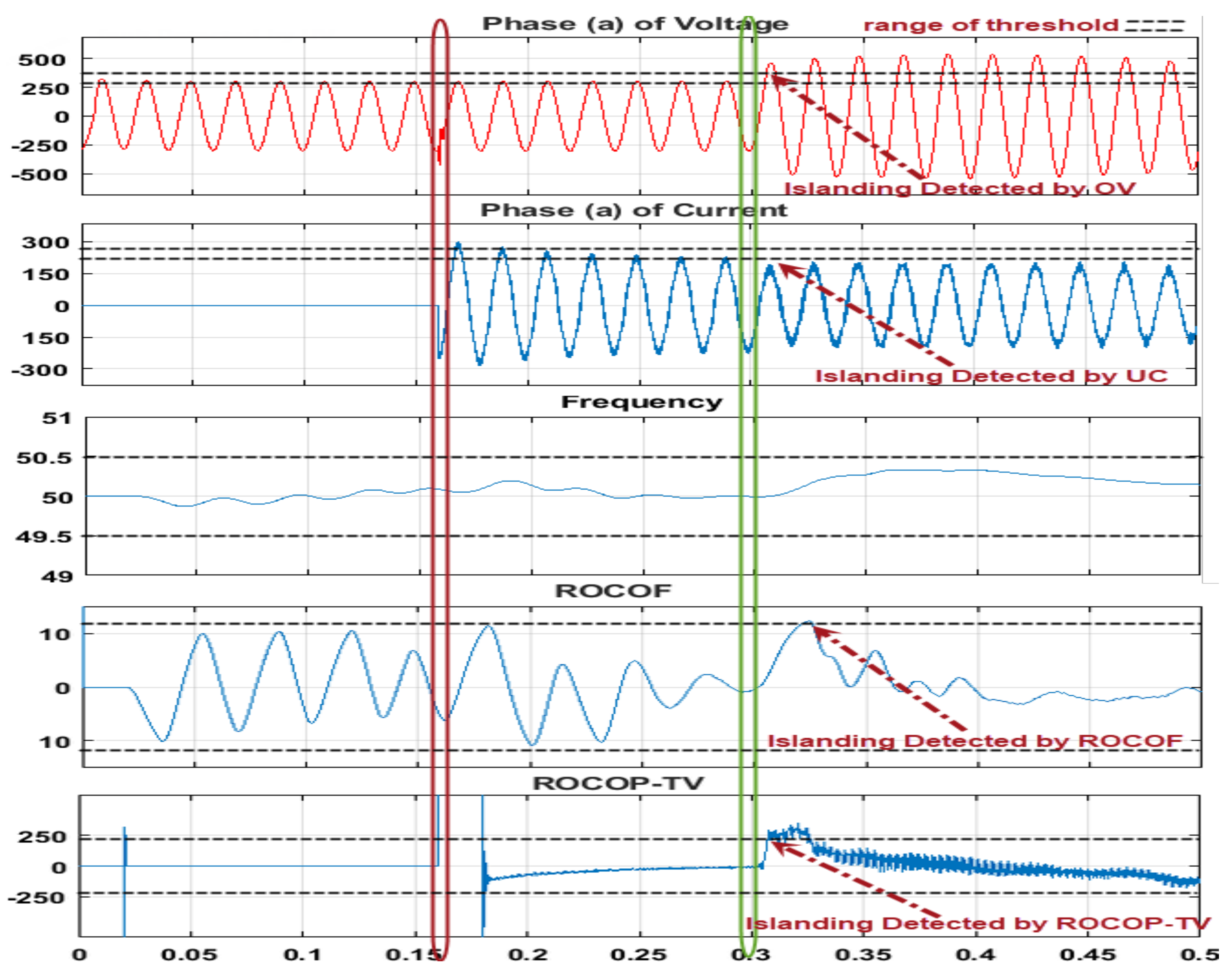
5. Comparison between the Proposed Technique and Two Recent Published Techniques

The proposed technique is compared with two hybrid techniques presented in [28,29]. The first one consists of the rate of change of power (ROCOP) combined with the terminal voltage (TV) (ROCOP-TV) technique presented in [28]. The flowchart depicted in Figure 25 shows that the islanding decision depends on the activation of the product signal between the ROCOP and TV protection relays. Additionally, these results are compared with passive techniques such as under/over-voltage (UOV), under/over current (UOI), under/over frequency (UOF), and rate of change of frequency (ROCOF) relays (df/dt) [28].
The second hybrid technique is about a combination of the rate of change of voltage (ROCOV) and the rate of change of active power (ROCOAP) presented in [29], and its flowchart is depicted in Figure 26. The ROCOAP is only activated when the islanding condition is suspected by ROCOV and the decision is taken if the value of voltage or frequency relay exceeds the thresholds detected by the IEEE standard. The results of these techniques are classified into two types: by applying varying load and grid faults as declared below.

5.1. Simulation Results of Different Values of Load for Islanding Phenomenon

Figure 27 presents the simulation result of applying islanding at 0.3 s in green color after disconnection of the circuit breaker that connects the DG with the utility grid in case of a low load value that consumes 25 kW, 10 kVAr. So in this figure, the connected load has a power less than the PV generation. It shows a rapid variation in ROCOP-TV, ROCOF, UC, and over-voltage (OV) relays until they exceed their threshold then islanding is detected. It is observed that ROCOP-TV and OV relays are similar in time detection and faster than ROCOF and UC relays [28]. Figure 28 presents the simulation results at the same time of disconnection using the combination between ROCOV and ROCOAP [29]. If the ROCOV is above zero, the ROCOAP is activated. Then, the over-voltage relay exceeds the threshold value in case of a lower load and hence islanding is detected.
Figure 29 and Figure 30 present the simulation results of applying relays in [28,29] successively in the case of the non-detection zone, by using loads that consume 103 kW, 0 kVAr. It is clear from these figures that no relay can detect islanding in NDZ. The case of large load for the two techniques in [28,29] are presented in Table 3.

5.2. Simulation Results of Different Types of Faults Impact

Faults are applied to clarify the accuracy of the proposed technique and the behavior is recorded in each case. For example, a double-phase fault is applied on the grid at 0.3 s in yellow color in the case of similarity between the load consumption power and the power generated from the DG, and its effect on islanding detection relays is mentioned in references [28,29] and is shown in Figure 31 and Figure 32, respectively. The performance of the other faults as single-phase fault, double-phase fault with the ground, three-phase fault, and three-phase fault with the ground are summarized in Table 3.

6. Conclusions

A hybrid passive-active fuzzy system is proposed for detecting the islanding phenomenon. In this proposed technique, a fuzzy inference system (FIS) is fed with readings of reactive power at three points, PV inverter, load, and grid. Using these three measurements, the FIS decides whether the islanding is detectable or a reactive power must be injected to be able to detect the islanding situation. Hence, the system acts as a passive detection technique if the decision of fuzzy is islanding, but if it cannot decide, the FIS system activates the active mode and injects reactive power. The proposed hybrid passive-active FIS-based islanding detection technique is compared with some passive anti-islanding detection techniques such as OC, UOF, ROCOF, UV, and ROCOP-TV presented in [28] also with the hybrid technique between ROCOV and ROCOAP presented in [29]. All these techniques are tested by considering the variation of loads and the grid faults in the power system. From the comparison, it is clarified that the rate of change of power with terminal voltage (ROCOP-TV) has superiority over some techniques in terms of the islanding detection time in some cases of large load, but it cannot detect the NDZ. On the other hand, a hybrid passive-active fuzzy system has superiority over all presented techniques in detecting islanding in NDZ and small load also it has accuracy like ROCOP-TV in differentiating between islanding cases and grid faults. Some future topics of interest are to extend the results of this paper to use a multi-PV DG operation work instead of a single-PV DG system, and also to implement this proposed technique practically. Another extension of this study is to include testing of adaptive fuzzy [30,31,32,33]. Additionally, a combination between active frequency drift [34] and rate of change of frequency [35] with ANFIS [36] can be introduced.

Author Contributions

Methodology, Y.A.E. and A.D.A.; software, Y.A.E.; supervision, S.A.-E., S.K., D.H.H., B.A.A. and A.D.A.; visualization, Y.A.E.; writing—original draft, Y.A.E. and S.K. All authors have read and agreed to the published version of the manuscript.

Funding

This research received no external funding.

Acknowledgments

I would like to introduce this work to my parents who are the main supporter in my life. I would especially like to thank my father Ahmed Shawky Elshrief for his generous support and heartfelt encouragement. His valuable advice, his professional and comprehensive guidance and his extensive knowledge enlightened my way in this research. I would like to thank him for helping and supporting me in my research.

Conflicts of Interest

The authors declare no conflict of interest.

References

  1. Baneshi, E.; Kolahduzloo, H.; Ebrahimi, J.; Mahmoudian, M.; Pouresmaeil, E.; Rodrigues, E. Coordinated Power Sharing in Islanding Microgrids for Parallel Distributed Generations. Electronics 2020, 9, 1927. [Google Scholar] [CrossRef]
  2. Elshrief, Y.A.; Abd-Elhaleem, S.; Abozalam, B.A.; Asham, A. Methods for protecting network from islanding danger. J. Eng. Res. 2021, 9, 230–242. [Google Scholar] [CrossRef]
  3. Elshrief, Y.A.; Abd-Elhaleem, S.; Zalam, B.A.; Asham, A.D. On active anti-islanding techniques: Survey. Indones. J. Electr. Eng. Comput. Sci. 2021, 22, 609–618. [Google Scholar] [CrossRef]
  4. Elshrief, Y.A.; Helmi, D.H.; Asham, A.D.; Abozalam, B.A.; Asham, A. Merits and Demerits of the Distributed Generations Connected to the Utility Grid. Menoufia J. Electron. Eng. Res. 2019, 28, 259–262. [Google Scholar] [CrossRef]
  5. Elshrief, Y.A.; Asham, A.D.; Abozalam, B.A.; Abd-Elhaleem, S. A new passive islanding detection technique for different zones in utility grid. J. Eng. Res. 2021, 9, 131–143. [Google Scholar] [CrossRef]
  6. Elshrief, Y.; Asham, A.; Helmi, D.; Abozalam, B. On Remote Anti-Islanding Detection Techniques. In Proceedings of the Future of Electricity Challenges and Opportunities, Cairo, Egypt, 6–8 March 2019; pp. 297–304. [Google Scholar]
  7. Haider, R.; Kim, C.H.; Ghanbari, T.; Bukhari, S.B.A.; Zaman, M.S.U.; Baloch, S.; Oh, Y.S. Passive islanding detection scheme based on autocorrelation function of modal current envelope for photovoltaic units. IET Gener. Transm. Distrib. 2017, 12, 726–736. [Google Scholar] [CrossRef]
  8. Karegar, H.K.; Shataee, A. Islanding detection of wind farms by THD. In Proceedings of the 2008 Third International Conference on Electric Utility Deregulation and Restructuring and Power Technologies, Nanjing, China, 6–9 April 2008; pp. 2793–2797. [Google Scholar]
  9. Freitas, W.; Huang, Z.; Xu, W. A practical method for assessing the effectiveness of vector surge relays for distributed generation applications. IEEE Trans. Power Deliv. 2005, 20, 57–63. [Google Scholar]
  10. Samui, A.; Samantaray, S.R. Assessment of ROCPAD Relay for Islanding Detection in Distributed Generation. IEEE Trans. Smart Grid 2011, 2, 391–398. [Google Scholar] [CrossRef]
  11. Reigosa, D.D.; Briz, F.; Blanco, C.; García, P.; Guerrero, J.M. Active Islanding Detection for Multiple Parallel-Connected Inverter-Based Distributed Generators Using High-Frequency Signal Injection. IEEE Trans. Power Electron. 2013, 29, 1192–1199. [Google Scholar] [CrossRef] [Green Version]
  12. Hashemi, F.; Mohammadi, M.; Kargarian, A. Islanding detection method for microgrid based on extracted features from differential transient rate of change of frequency. IET Gener. Transm. Distrib. 2017, 11, 891–904. [Google Scholar] [CrossRef]
  13. Raza, S.; Mokhlis, H.; Arof, H.; Laghari, J.; Wang, L. Application of signal processing techniques for islanding detection of distributed generation in distribution network: A review. Energy Convers. Manag. 2015, 96, 613–624. [Google Scholar] [CrossRef] [Green Version]
  14. Kim, M.-S.; Haider, R.; Cho, G.-J.; Kim, C.-H.; Won, C.-Y.; Chai, J.-S. Comprehensive Review of Islanding Detection Methods for Distributed Generation Systems. Energies 2019, 12, 837. [Google Scholar] [CrossRef] [Green Version]
  15. Alshareef, S.; Talwar, S.; Morsi, W.G. A New Approach Based on Wavelet Design and Machine Learning for Islanding Detection of Distributed Generation. IEEE Trans. Smart Grid 2014, 5, 1575–1583. [Google Scholar] [CrossRef]
  16. ElNozahy, M.S.; El-Saadany, E.F.; Salama, M.M.A. A robust wavelet-ANN based technique for islanding detection. In Proceedings of the 2011 IEEE Power and Energy Society General Meeting, Detroit, MI, USA, 24–28 July 2011; pp. 1–8. [Google Scholar]
  17. Mohanty, S.R.; Kishor, N.; Ray, P.K.; Catalão, J.P.S. Comparative Study of Advanced Signal Processing Techniques for Islanding Detection in a Hybrid Distributed Generation System. IEEE Trans. Sustain. Energy 2015, 6, 122–131. [Google Scholar] [CrossRef]
  18. Lidula, N.W.A.; Rajapakse, A.D. A Pattern-Recognition Approach for Detecting Power Islands Using Transient Signals—Part II: Performance Evaluation. IEEE Trans. Power Deliv. 2012, 27, 1071–1080. [Google Scholar] [CrossRef]
  19. Samantaray, S.R.; El-Arroudi, K.; Joos, G.; Kamwa, I. A Fuzzy Rule-Based Approach for Islanding Detection in Distributed Generation. IEEE Trans. Power Deliv. 2010, 25, 1427–1433. [Google Scholar] [CrossRef]
  20. Wang, G.; Wang, J.; Zhou, Z.; Wang, Q.; Wu, Q.; Jiang, X.; Santana, E. State variable technique islanding detection using time-frequency energy analysis for DFIG wind turbine in microgrid system. ISA Trans. 2018, 80, 360–370. [Google Scholar] [CrossRef]
  21. Abd-Elkader, A.G.; Allam, D.F.; Tageldin, E. Islanding detection method for DFIG wind turbines using artificial neural networks. Int. J. Electr. Power Energy Syst. 2014, 62, 335–343. [Google Scholar] [CrossRef]
  22. Matic-Cuka, B.; Kezunovic, M. Islanding Detection for Inverter-Based Distributed Generation Using Support Vector Machine Method. IEEE Trans. Smart Grid 2014, 5, 2676–2686. [Google Scholar] [CrossRef]
  23. Azim, R.; Zhu, Y.; Saleem, H.A.; Sun, K.; Li, F.; Shi, D.; Sharma, R. A decision tree based approach for microgrid islanding detection. In Proceedings of the 2015 IEEE Power & Energy Society Innovative Smart Grid Technologies Conference (ISGT), Washington, DC, USA, 18–20 February 2015; pp. 1–5. [Google Scholar]
  24. Khamis, A.; Xu, Y.; Dong, Z.Y.; Zhang, R. Faster Detection of Microgrid Islanding Events using an Adaptive Ensemble Classifier. IEEE Trans. Smart Grid 2016, 9, 1889–1899. [Google Scholar] [CrossRef]
  25. Ahmadipour, M.; Hizam, H.; Othman, M.L.; Radzi, M.A.M.; Chireh, N. A novel islanding detection technique using modified Slantlet transform in multi-distributed generation. Int. J. Electr. Power Energy Syst. 2019, 112, 460–475. [Google Scholar] [CrossRef]
  26. Mishra, M.; Rout, P.K. Detection and classification of micro-grid faults based on HHT and machine learning techniques. IET Gener. Transm. Distrib. 2017, 12, 388–397. [Google Scholar] [CrossRef]
  27. Bitaraf, H.; Sheikholeslamzadeh, M.; Ranjbar, A.M.; Mozafari, B. Neuro-fuzzy islanding detection in distributed generation. In Proceedings of the IEEE PES Innovative Smart Grid Technologies, Tianjin, China, 21–24 May 2012; pp. 1–5. [Google Scholar]
  28. Elshrief, Y.A.; Helmi, D.H.; Abd-Elhaleem, S.; Abozalam, B.A.; Asham, A.D. Fast and accurate islanding detection technique for microgrid connected to photovoltaic system. J. Radiat. Res. Appl. Sci. 2021, 14, 210–221. [Google Scholar] [CrossRef]
  29. Seyedi, M.; Taher, S.A.; Ganji, B.; Guerrero, J. A Hybrid Islanding Detection Method Based on the Rates of Changes in Voltage and Active Power for the Multi-Inverter Systems. IEEE Trans. Smart Grid 2021, 12, 2800–2811. [Google Scholar] [CrossRef]
  30. Elshrief, Y.A.; Atlam, G.A.; Abozalam, B.A. Adaptive–fuzzy logic power filter for nonlinear systems. IOSR J. Electr. Electron. Eng. 2016, 11, 66–73. [Google Scholar] [CrossRef]
  31. ELshrief, Y.A.; Atlam, G.A.; Abozalalm, B.A. Adaptive Hysteresis Active Power Filter using Fuzzy-Logic Controller for Nonlinear Systems. Menoufia J. Electron. Eng. Res. 2017, 26, 99–112. [Google Scholar] [CrossRef]
  32. Elshrief, Y.A.; Elakbawy, H.F.; Galal, A.A.; Abozalam, B.A. Comparison between the fixed_band HCC and adaptive HCC used for APF control. IOSR J. Electr. Electron. Eng. 2016, 11, 54–59. [Google Scholar] [CrossRef]
  33. Wan, J.; Hua, W.; Wang, B. Compulsory Islanding Transition Strategy Based on Fuzzy Logic Control for a Renewable Microgrid System. Math. Probl. Eng. 2021, 2021, 9959222. [Google Scholar]
  34. Elshrief, Y.A.; Abd-Elhaleem, S.; Asham, A.D.; Abozalam, B.A. AI protection Algorithms for PV-Grid Connection System. In Proceedings of the 2020 International Conference on Innovative Trends in Communication and Computer Engineering (ITCE), Aswan, Egypt, 8–9 February 2020; pp. 341–345. [Google Scholar]
  35. Elshrief, Y.A.; Helmi, D.H.; Asham, A.D.; Abozalam, B.A.; Asham, A. ROCOF for detecting Islanding of Photovoltaic system. Menoufia J. Electron. Eng. Res. 2019, 28, 255–258. [Google Scholar] [CrossRef]
  36. Karaboga, D.; Kaya, E. Adaptive network based fuzzy inference system (ANFIS) training approaches: A comprehensive survey. Artif. Intell. Rev. 2019, 52, 2263–2293. [Google Scholar] [CrossRef]
Figure 1. Power flow between the utility grid and distributed generation source.
Sustainability 14 06325 g001
Figure 2. Non-detection zone (the non-detected area) [2].
Sustainability 14 06325 g002
Figure 3. The three-level VSC stage connected to the inverter in the DG power stage.
Sustainability 14 06325 g003
Figure 4. The Simulink implementation of the VSC control.
Sustainability 14 06325 g004
Figure 5. Schematic diagram of the proposed technique.
Sustainability 14 06325 g005
Figure 6. Flowchart of the proposed technique.
Sustainability 14 06325 g006
Figure 7. Matlab implementation of the proposed technique.
Sustainability 14 06325 g007
Figure 8. Membership function for reactive power of PV (X1).
Sustainability 14 06325 g008
Figure 9. Membership function for reactive power of grid (X2).
Sustainability 14 06325 g009
Figure 10. Membership function for reactive power of load (X3).
Sustainability 14 06325 g010
Figure 11. Membership function for the island (Q1).
Sustainability 14 06325 g011
Figure 12. Membership function for disturb (Q2).
Sustainability 14 06325 g012
Figure 13. Islanding detection in the normal case.
Sustainability 14 06325 g013
Figure 14. Islanding detection in NDZ case.
Sustainability 14 06325 g014
Figure 15. Single-phase fault (normal case).
Sustainability 14 06325 g015
Figure 16. Double-phase fault (normal case).
Sustainability 14 06325 g016
Figure 17. Double-phase fault with the ground (normal case).
Sustainability 14 06325 g017
Figure 18. Three-phase fault (normal case).
Sustainability 14 06325 g018
Figure 19. Three-phase fault with the ground (normal case).
Sustainability 14 06325 g019
Figure 20. Single-phase fault (NDZ case).
Sustainability 14 06325 g020
Figure 21. Double-phase fault (NDZ case).
Sustainability 14 06325 g021
Figure 22. Double-phase fault with the ground (NDZ case).
Sustainability 14 06325 g022
Figure 23. Three-phase fault (NDZ case).
Sustainability 14 06325 g023
Figure 24. Three-phase fault with the ground (NDZ case).
Sustainability 14 06325 g024
Figure 25. The flowchart of the ROCOP-TV technique [28].
Sustainability 14 06325 g025
Figure 26. The flowchart of the ROCOV and ROCOAP techniques [29].
Sustainability 14 06325 g026
Figure 27. Islanding detection relays when there is low power load in [28].
Sustainability 14 06325 g027
Figure 28. Islanding detection relays when there is low power load in [29].
Sustainability 14 06325 g028
Figure 29. Islanding detection relays of NDZ in [28].
Sustainability 14 06325 g029
Figure 30. Islanding detection relay of NDZ in [29].
Sustainability 14 06325 g030
Figure 31. Double-phase fault in NDZ in [28].
Sustainability 14 06325 g031
Figure 32. Double-phase fault in NDZ in [29].
Sustainability 14 06325 g032
Table 1. Standard IEEE 1547 for anti-islanding techniques [2].
ParametersStandard
Range of voltage88% ≤ V ≤ 110%
Range of frequency49.3 HZ ≤ f ≤ 50.5 HZ
The maximum time for islanding detection2 s
Total harmonic distortion (THD %)≤5%
Table 2. Fuzzy rules for hybrid islanding proposed system.
PV-QGrid-QLoad-QIslandingDisturb
SmallSmallSmallSmallLarge
SmallMediumSmallSmallSmall
SmallLargeSmallSmallSmall
SmallSmallMediumMediumMedium
SmallMediumMediumSmallSmall
SmallLargeMediumSmallSmall
SmallSmallLargeMediumMedium
SmallMediumLargeSmallMedium
SmallLargeLargeSmallSmall
MediumSmallSmallMediumSmall
MediumSmallMediumLargeMedium
MediumSmallLargeLargeSmall
MediumMediumSmallSmallMedium
MediumMediumMediumSmallSmall
MediumMediumLargeMediumSmall
MediumLargeSmallSmallSmall
MediumLargeMediumSmallSmall
MediumLargeLargeSmallSmall
LargeSmallSmallSmallLarge
LargeSmallMediumLargeSmall
LargeSmallLargeLargeSmall
LargeMediumSmallMediumSmall
LargeMediumMediumSmallSmall
LargeMediumLargeSmallSmall
LargeLargeSmallSmallMedium
LargeLargeMediumSmallSmall
LargeLargeLargeSmallSmall
Table 3. The hybrid fuzzy inference system detection time compared with techniques in [28,29].
CasesTime of Detection (Seconds) of AI Relays
Traditional Techniques in [28]Proposed in [28]Proposed in [29]Proposed
OCUVUFOFROCOFROCOP_TVROCOV &ROCOAPHybrid Fuzzy
Case A (generation < load)-0.0082---0.00820.01210.0092
Case B (generation = load)-------0.0652
Case C (generation > load)----0.02500.00970.01110.0092
Single-phase fault-0.0074--0.0200-0.0171-
Double-phase fault0.00930.0093--0.0350-0.0082-
Double-phase fault with ground0.00730.0073----0.0077-
Three-phase fault0.00730.0073--0.0254-0.0056-
Three-phase fault with ground0.00730.0073--0.0253-0.0056-
Publisher’s Note: MDPI stays neutral with regard to jurisdictional claims in published maps and institutional affiliations.

