This section elaborates on the power system network as the object of the proposed control method simulation, i.e., the Jeju Island power system. A comprehensive explanation regarding the result of several cooperation concepts with grid code requirement standards, e.g., frequency nadir and rate of change of frequency (RoCoF), will be discussed in this section. Furthermore, the comparison studies based on two contingencies are carried out, i.e., the first HVDC interconnection and the largest generator capacities on Jeju Island. In this simulation, the total simulation time was carried out at 60 s to define power system stability standards after contingencies. In addition, each of the contingency studies is applied two seconds after the simulation is initiated. Therefore, the HVDC link with the cooperation concept controller would maintain the stability and reliability of the power system, especially when contingencies occur.
4.1. Jeju Island Power System
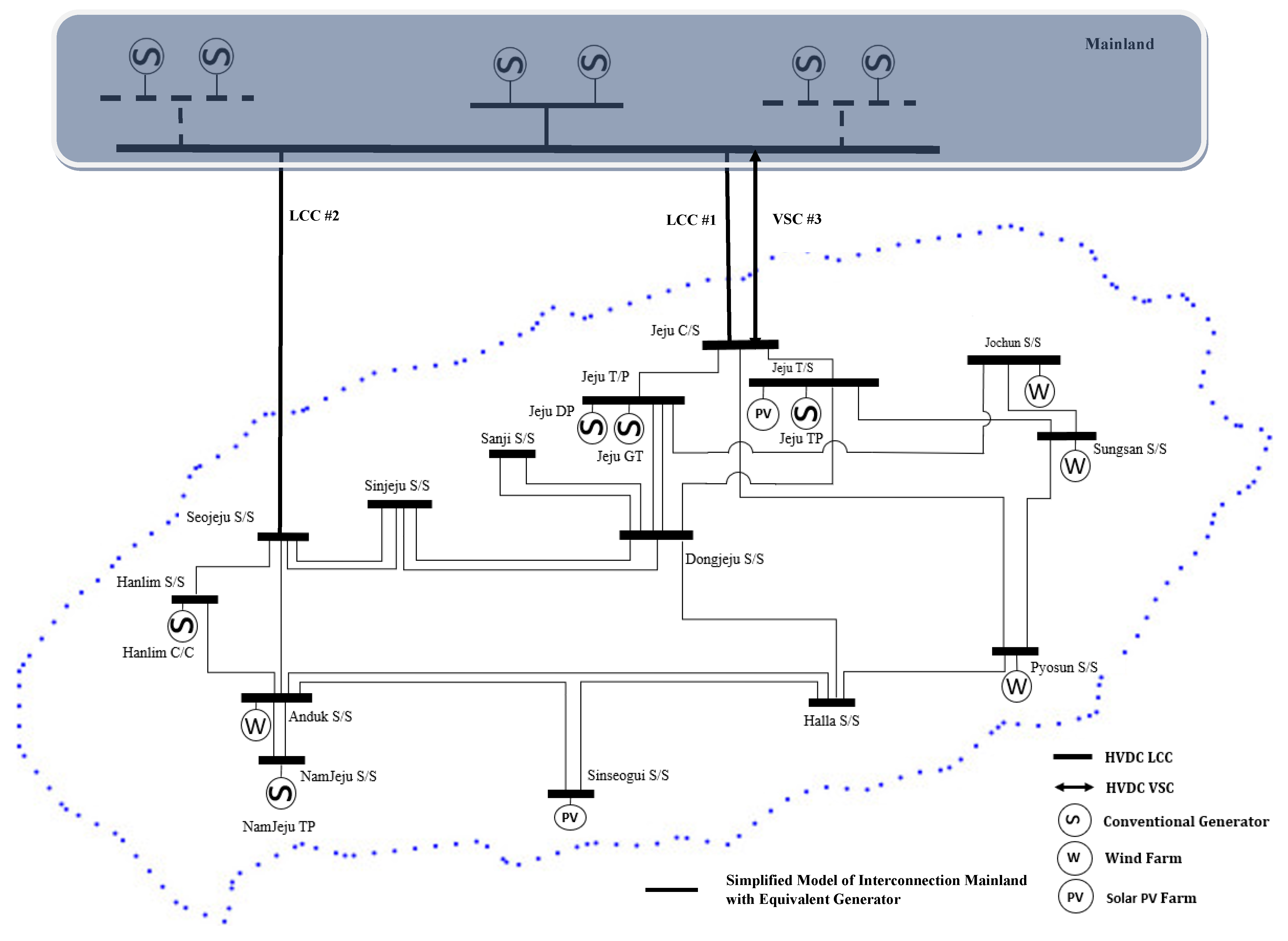
The configuration and description of the Jeju Island power system are illustrated in
Figure 8 [
29]. Two characteristic considerations, i.e., the characteristic generator model and the generator total capacity, are approached to express the modeling of the mainland network system. The characteristic of the generator model is reflected in the largest percentage of generation in the Korean power system, i.e., coal-fired power generation [
1]. Moreover, coal-fired power generation is similar to thermal power plants because of their working principles. From a power system researcher’s point of view, thermal power plants could be modeled as a GENROU, which refers to the 2030 Eastern Interconnection Grid Report [
30]. The capacity value of an equivalent generator on the mainland will be modeled in
Appendix A especially in
Table A1 according to the total approach of generator capacities in the mainland power system. Furthermore, as explained in [
30], to ensure the correctness of simulation results, the original capacities are replaced with an equal value of 1.1 times that of the generator’s apparent output. In contemplating this concept, we can ensure a good estimation of the actual machine capacity. The Jeju Island power system consists of four generators that are evenly distributed in 15 bus operation systems and three HVDCs of two types, i.e., LCC and VSC. In the first and second interconnection, the LCC is applied between the mainland and Jeju Island, which were constructed in 1998 and 2013, respectively. The installation capacity for two LCC HVDCs subsequently is 180 kV/300 MW and 250 kV/400 MW. Furthermore, in this simplified model of the Korean power system, the total load on Jeju Island is 750 MW.
For generation and normal HVDC operation, the capacity will be 250 MW and 500 MW, respectively. In the previous section, the explanation regarding the unique characteristic of Jeju Island was introduced due to the multi-infeed application of HVDC lines. As reflected in several studies already mentioned in the introduction section, VSC HVDC with a capacity of 150 kV/200 MW is a planned installation that would be approached in the network system model of the Korean power system. Therefore, the largest generator located in the Namjeju (170) bus and the first HVDC interconnection that was constructed in 1998 with the capacity of 180 kV/300 MW are used for contingency simulation studies. The normal operation or operational capacity of the HVDC system would be set based on chosen values, from the first until the third HVDC connection is 150 MW, 250 MW, and 100 MW, respectively. Considering [
31], the limit of the HVDC operation reserve could be set according to the rated power capacity. Furthermore, in terms of frequency stability operation, the limit reserve operation of the second HVDC interconnection and VSC type is set to be fully available (from 250 MW to 400 MW and from 100 to 200 MW subsequently). The limit of LCC operation based on the algorithm will be discussed in the section on contingencies studies.
4.2. Contingency on The First HVDC Interconnection Trip
In this section, the keen analysis of the first HVDC interconnection trip will be evaluated. Moreover, a comparison between several cooperation concepts based on reserve operation is analyzed with several grid parameter standards, e.g., the active power of both HVDC types and frequency in both synchronous areas. In normal operation, the active power limit of the first HVDC was maintained at around 150 MW, and the value for each pole was around 75 MW. The interconnection trip was applied after 2 s from initialization. In addition, the frequency response based on conventional and proposed methods of cooperation concepts, i.e., combining FCP with GSS, is discussed. Moreover, the values of frequency nadir and RoCoF for the first HVDC interconnection trip are listed in
Table 7.
As illustrated in
Figure 9, the proposed method shows an exceptional improvement in frequency nadir values, i.e., 59.87539 Hz, during disturbance fault for both synchronous areas. Moreover, the RoCoF of the proposed method shows a smaller value, which indicates a lower deviation in frequency after the first HVDC interconnection trip and the value of RoCoF without reserve control will become the highest and susceptible to transient operation. Three stages of reserve operation and the maximum frequency nadir value are described in
Figure 9. The proposed method with grid stability standard operation on VSC types shows outstanding improvement in the network system’s stability for each frequency stage, especially in the smaller power systems. The steady-state frequency value is maintained around 22 s after disturbance. In addition, the primary frequency response based on reserves operation, i.e., sharing FCR, shows a higher value compared to droop.
The frequency of the mainland power system is shown in
Figure 10. The application of the cooperation concepts shows an improvement in oscillation during the first HVDC interconnection contingency situation. After applying several concepts, we can reduce the oscillation in the mainland frequency. The exchange of the FCR concept shows an improvement in oscillation by reducing the deviation frequency value up to 0.0285 Hz in the without-control situation. However, this concept is not recommended because the frequency nadir and steady-state values in Jeju Island are lower than the grid code standard [
32].
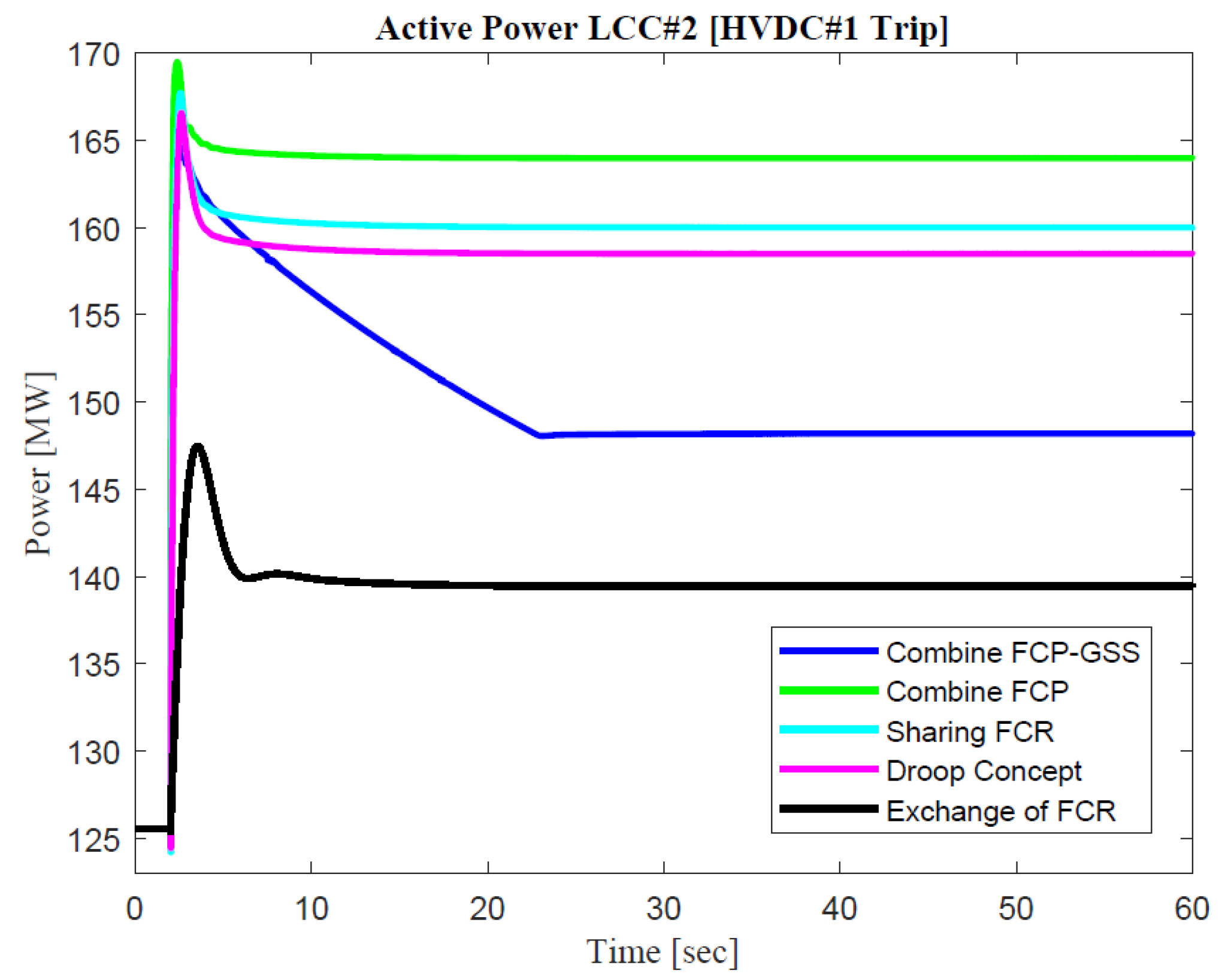
As shown in
Figure 11, several active power responses from the second HVDC interconnection are described. The characteristic of active power leans on the controller modeling and the algorithm for the proposed method. The additional virtual inertia part in the combined FCP concepts demonstrates the agile response of active power. In addition, the limit of LCC reserves’ operation in the GSS concept is described based on the frequency value in both synchronous areas. Exchange of FCR is the only concept that considers the cost-efficiency of deploying the interconnection, and due to this reason, the active power characteristic will be the smallest value compared to the other concepts.
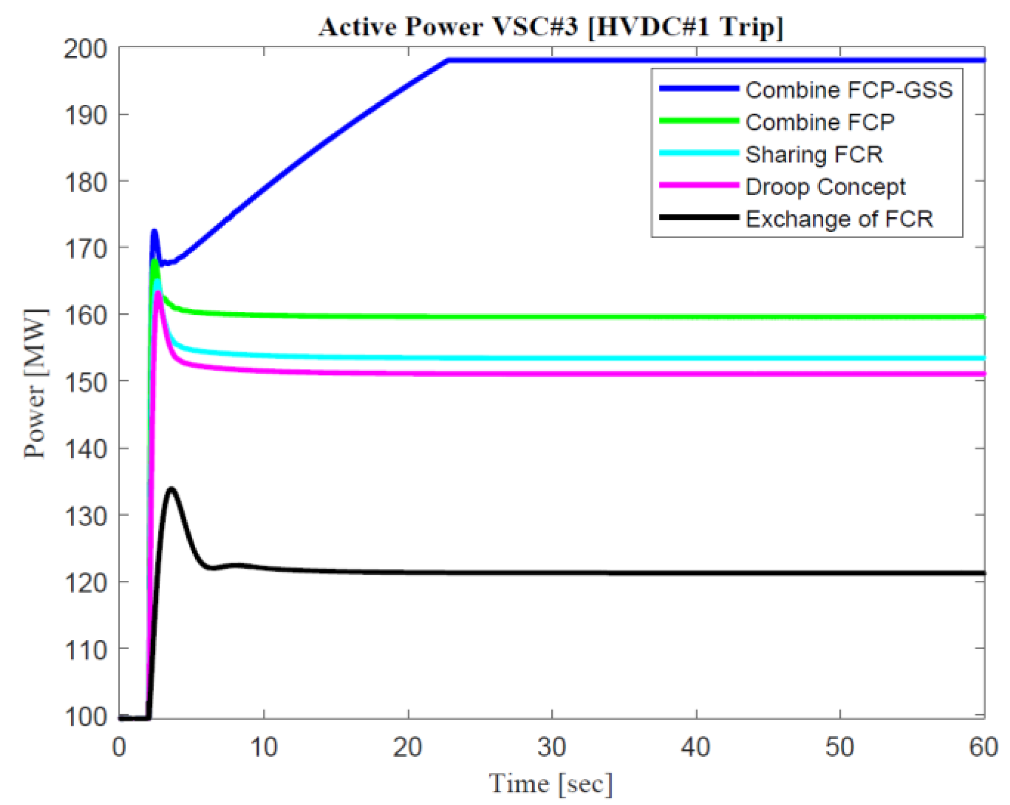
As described in
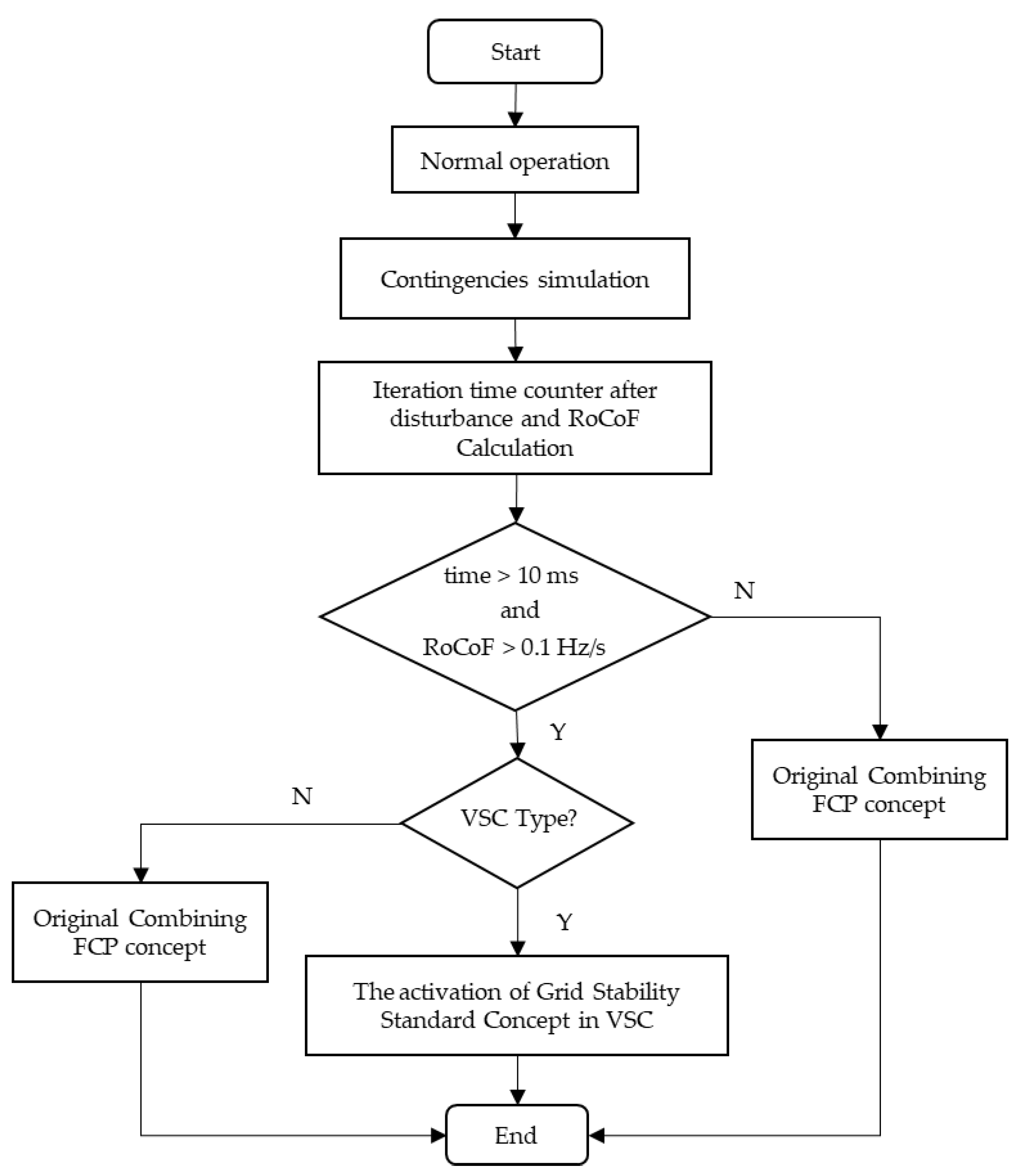
Figure 12, the enormous gap between the proposed control method and the conventional cooperation concepts is depicted. Moreover, the VSC line has an interesting point about agility and reliability. An exceptional point of the proposed method could be illustrated and compared in the combined FCP concept. An additional reserve is applied after 10 ms, and a RoCoF value higher than 0.1 Hz/s. The active power of VSC in the combined FCP-GSS concepts has the highest value compared to the other concepts. The limitation of active power would be activated around 22 s because the DC transmission line has reached its maximum capacity.
After several responses, it can be concluded the proposed case study i.e., mainland—Jeju island is similar to the GB-CE case, which expresses a slight difference in the gain value of the HVDC reserve control. Moreover, the operation of the sharing FCR and combining FCP between two synchronous areas does not always become the optimum value, as described in the previous
Section 3.1 especially in the NO-CE interconnection. Furthermore, there is no significant difference in the droop concept compared to the other gain value in the HVDC interconnection between the mainland and Jeju Island. However, this occurs due to the limitation of reserve availability in both synchronous areas.
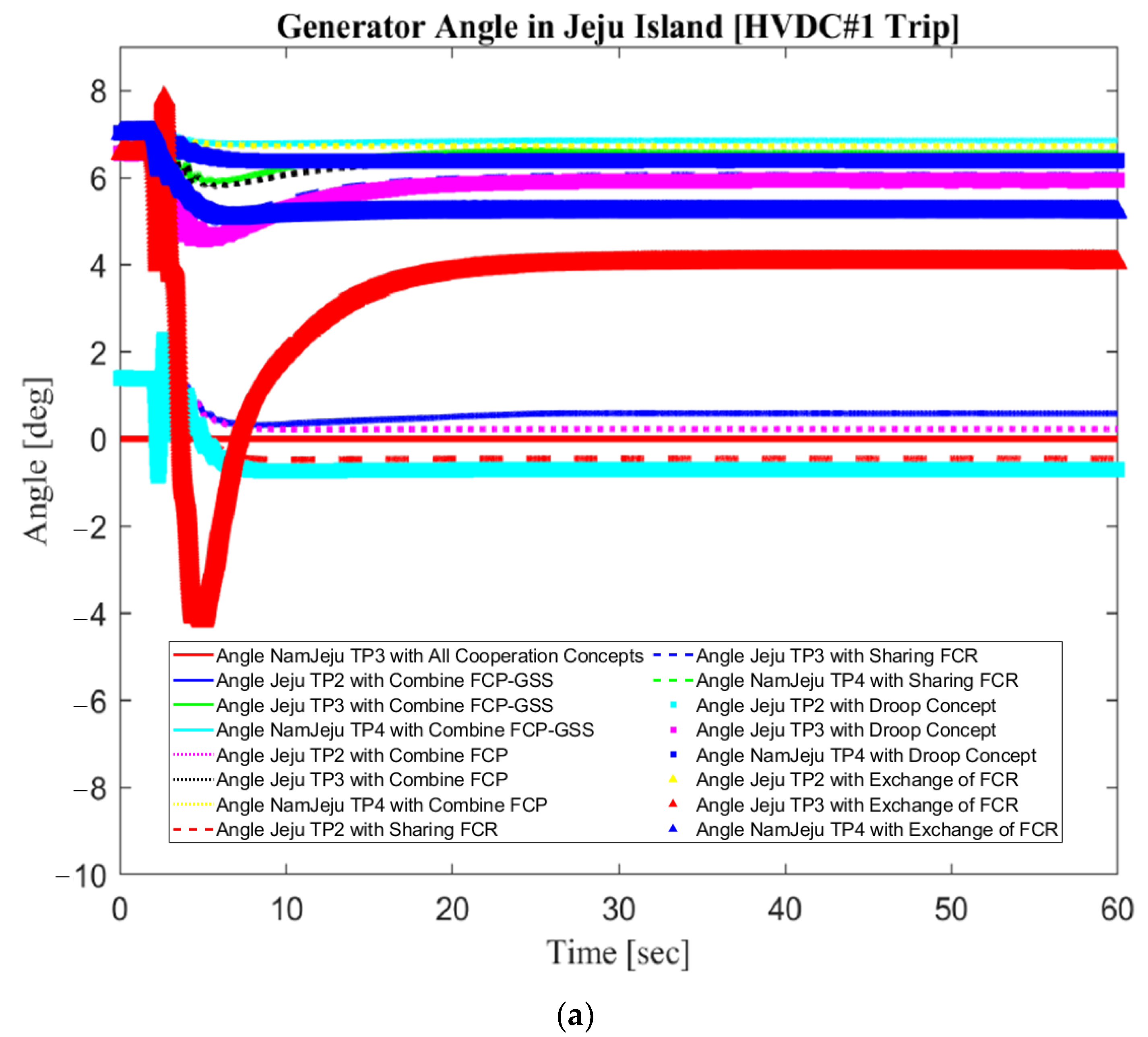
Generator angle responses for both synchronous areas are used to determine the correct value of the converter bus angle between VSC interconnection lines. There are four generators on Jeju Island that are used to determine stability and secure reserve operation according to the grid code through HVDC. As reflected in
Figure 13, through the combined FCP-GSS concept, the angle of the generator between the mainland and Jeju Island would be the same as in the previous condition before the fault situation due to the high gain value and fast response of balancing. However, the exchange of FCR is the only concept that shows the wide gap during fault conditions because the generator value must change following the gain value in terms of balancing concepts between two synchronous areas.
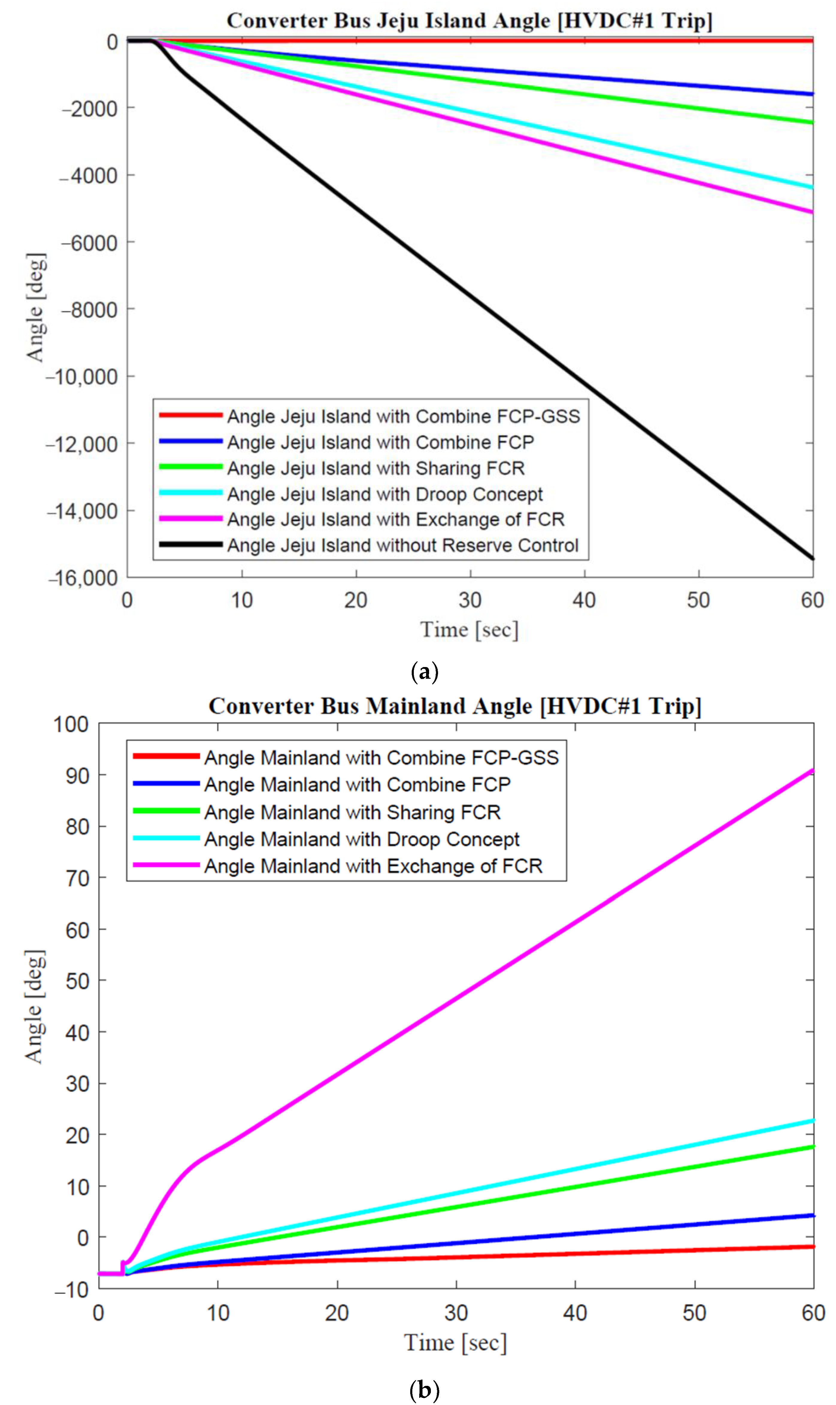
The fundamental differences between the converter bus angle and the generator angle are described as reflected in the synchronous reference frame and relative angle, respectively. The synchronous reference frame represents how the angles would change concerning a Park Transformation, i.e., a theoretical rotating reference frame based on the system’s nominal frequency. When a transient stability simulation converges after disturbance with the addition of power modulation. This condition leads to a new steady-state frequency that is higher than the nominal frequency; then, the converter bus angles will naturally continue to increase toward infinity. This situation will not indicate instability as long as the angles in relation to one another converge upon a new steady state. On the other hand, the generator in both synchronous areas will use the relative angle concept in which the setting is specified of the terminal bus angle, especially in the slack generator bus, to determine power system stability after disturbances.
Although the wide range value occurs, the stability and reliability system was checked through generator angle response value in two synchronous areas. In addition, the converter bus angle belongs to one of the important parameters to improve power system balancing stability through HVDC reserve operation. As described in the mainland network, an exchange of the FCR concept shows the increasing value of angle due to the imbalance between generation and load conditions. According to
Figure 14, the improvement of angle deviation value using a combined FCP-GSS concept could be obtained through a converter bus angle synchronous reference frame.
4.3. Contingency on The Largest Generation Trip
In this section, the keen analysis of the largest generation trip on the Jeju Island power system will be evaluated. Moreover, a comparison between several cooperation concepts based on reserve operation is described with several grid parameter standards, i.e., the active power of both HVDC types and the frequency in both synchronous areas are used for the evaluation. In the contingency operation, the active power limit of three HVDC interconnections was maintained at 300, 400, and 200 MW, respectively. The largest generation trip was applied after 2 s from initialization. In addition, the frequency response based on conventional and proposed methods of cooperation concepts, i.e., combining FCP with GSS, is explained. Furthermore, the value of frequency nadir and RoCoF for the largest generation trip are listed in
Table 8.
During contingency simulation of the largest generator trip, the four concepts that start from the proposed method until sharing FCR could be proposed to the transmission system operator for grid frequency stability in the Jeju Island power system. As illustrated in
Figure 15, the frequency nadir of sharing FCR is above 59.4 Hz. Moreover, during steady-state operation, the frequency of sharing FCR is maintained above 59.8 Hz. Similar to the previous explanation regarding additional virtual inertia, the frequency nadir of combine FCP on Jeju Island has the highest value of the other conventional cooperation concepts. Furthermore, the additional virtual inertia is illustrated based on the RoCoF value, which explained that the deviation in frequency will be the smallest compared to the other concepts.
The additional reserves power through combined FCP-GSS shows the highest value for nadir and steady-state conditions. The nadir frequency value is 59.9237 Hz, and the steady-state condition is 59.985 Hz. However, the exchange of the FCR concept is not recommendable for reserves operation through the HVDC cause of nadir frequency value is 59.28379 Hz lower than the grid code standard in Jeju Island.
As depicted in
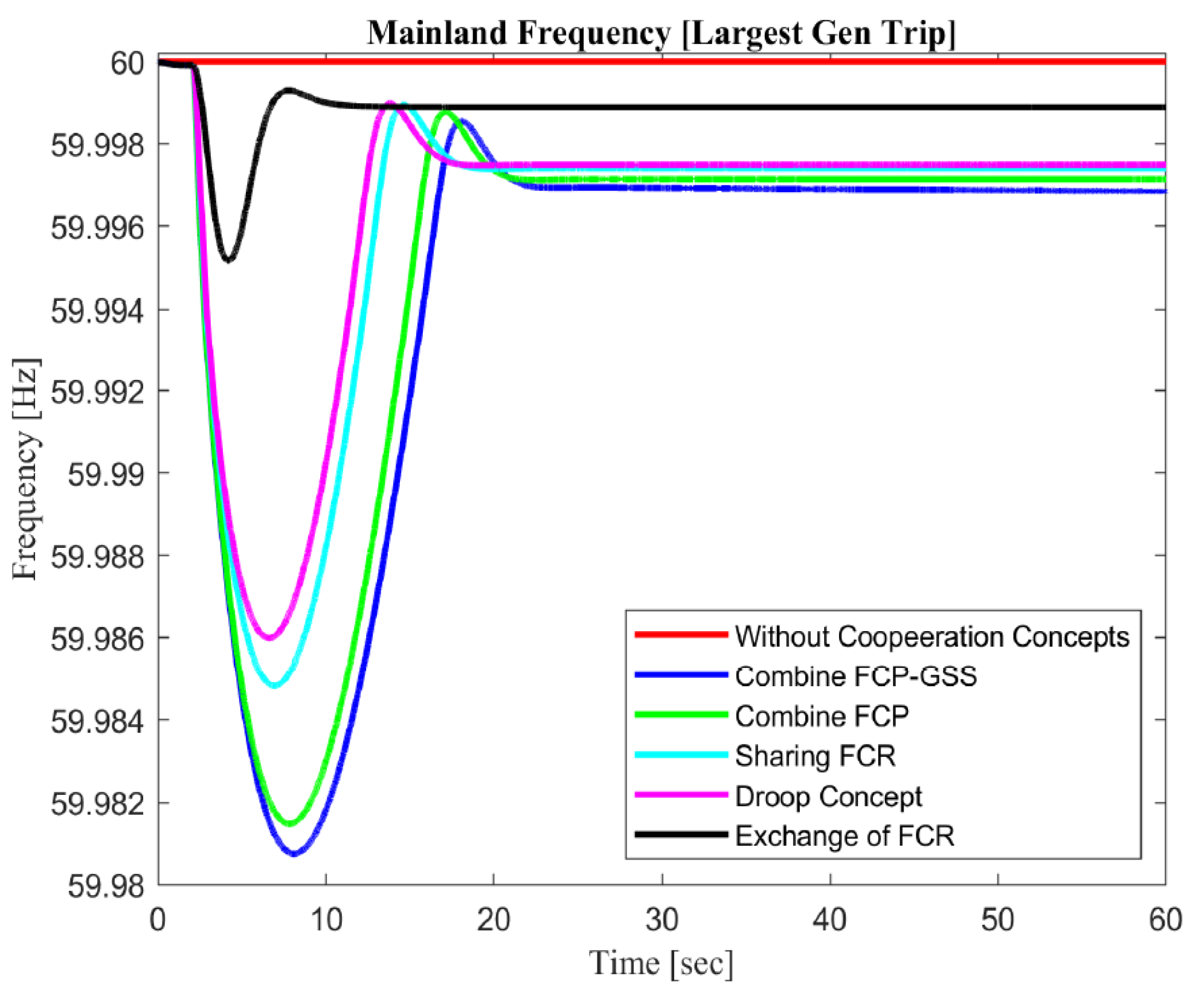
Figure 16, the proposed method has a lower frequency nadir value than the other conventional cooperation concepts. This phenomenon occurs due to an unbalanced power system on Jeju Island after 2 s. The mainland power system tried to supply more reserves. Meanwhile, there is no deactivation load on the mainland, and the available power on the mainland is reduced to support reserve power to the Jeju Island power system. In addition, power system stability studies, which are explained in
Section 2.4, can describe this phenomenon. Furthermore, when the proposed cooperation concepts between synchronous areas are utilized, the frequency nadir in the mainland power system becomes one of the concern parameters as well. As shown in
Figure 16, the value of nadir does not significantly change according to Korea’s power system grid code, i.e., 59.98 Hz, while the minimum value for load activation shedding is 59.8 Hz. As described in
Section 3.7, the proposed method is reflected in the scale and inertia of the network system size by adjusting the activation of generator participation. Through this approach, the proposed method will optimize the grid parameter standard even though the equal network system size is. Through additional reserves power in
Figure 17, we can see the improvement in nadir and steady-state frequency in Jeju Island, along with the reduction of nadir and steady-state frequency in the mainland network. Moreover, the nadir frequency value on the mainland is appropriate for the grid code standards. In addition, if the proposed method is applied in the equivalent power system, the nadir frequency and RoCoF could be maintained and sustained, reflected in the frequency grid code. On the other hand, the frequency nadir in the contingency area could be improved significantly.
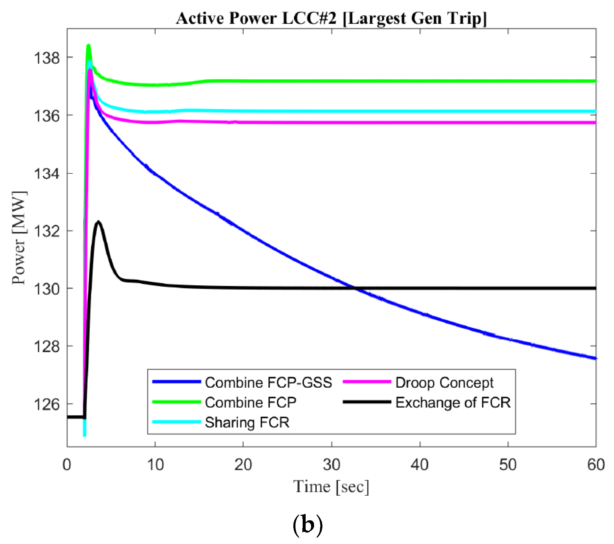
As described in
Figure 17, the active power of LCC#1 and LCC#2 with the combined FCP concept shows the high improvement value for active power caused by additional virtual inertia. Sharing FCR and combine FCP show the higher active power value during steady-state conditions caused by the bias factor value between synchronous areas. Combine FCP-GSS shows the reduction in the active power value caused by the activation of additional grid stability parameter standards, i.e., voltage and angle, in the VSC bus interconnection. As shown in
Figure 17 and
Figure 18, the active power of LCC#1 and LCC#2 has a limit of LCC operation value for each pole, which is set to be 150 MW and 200 MW, respectively. The fundamental difference between LCC#1 and LCC#2 is only the initial set point of normal operation. Furthermore, as already explained in the previous section, additional active power between LCC#1 and LCC#2 is similar for all cooperation concepts. This condition demonstrates and proves the characteristic of HVDC controlled modeling in MIDC power systems which have similar deviation values according to HVDC types.
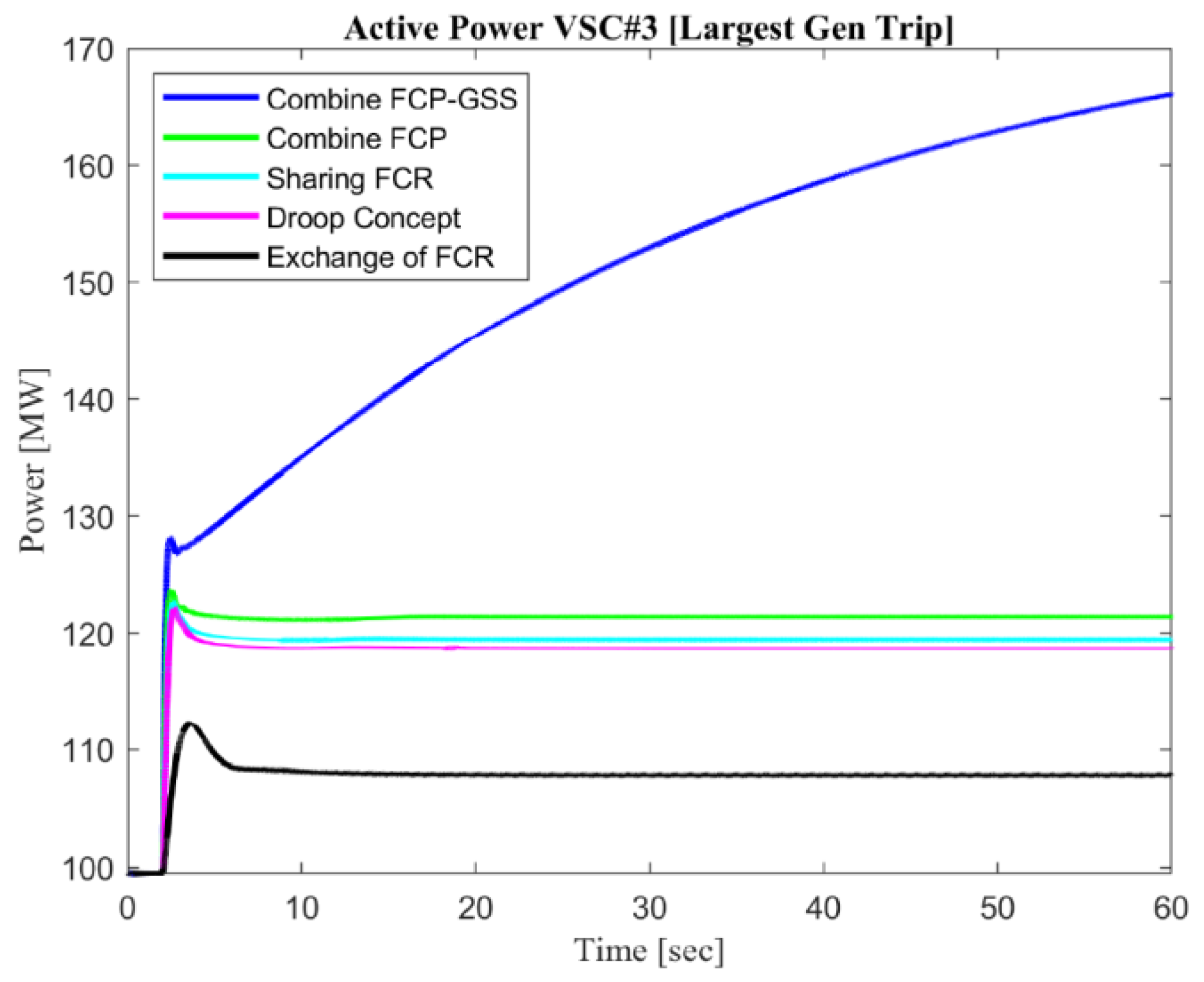
As described in
Figure 18, the tremendous gap between the proposed control method with the conventional cooperation concepts is illustrated. A significant point of VSC is the swiftness and the accuracy during contingencies response. The main point of the proposed method could be described and compared in the combined FCP concept. An additional reserve is carried out after 10 ms and a RoCoF value higher than 0.1 Hz/s. The active power of VSC in the combined FCP-GSS concepts has the highest value compared to the other concepts. In this contingency, there is no limitation of active power because the DC transmission line’s maximum capacity is higher compared to the active power operation value.
This explanation is also implied for a conventional concept, such as the exchange of the FCR concept. In this concept, we can see the nadir frequency value on the mainland is the highest value of the other concepts because the reserve power through the VSC type from the mainland to Jeju Island has the smallest value compared to the other concepts. As described in
Figure 17 and
Figure 18, the additional active power of the exchange FCR concept in LCC is less than 7.5 MW, and VSC is around 11 MW. Moreover, we calculate additional reserve operation through the LCC and VSC interconnection around 26 MW. Meanwhile, for the other concepts, the additional reserves power around 12.5 MW for LCC and 12 MW for VSC.
As shown in
Figure 19, the generator angle response on the mainland is increasing, causing the generator on the mainland to produce additional reserves of power to support Jeju Island. Meanwhile, due to the deactivation of the largest generator on Jeju Island, the angle value in NamJeju TP 4 becomes zero after contingency operation. The improvement of additional active power was activated based on a deviation between the converter bus on the mainland and Jeju Island. That is the reason, through the combined FCP-GSS concept, the deviation value of angle potential decreased. In exchange for the FCR concept, the generator angle response value in the mainland after the disturbance has slight oscillation because the additional reserves are small compared to the other concepts.


