Abstract
The aeroponic plant root environment has a significant role in producing high-quality seed tuber potatoes. However, in lowland and tropical regions, the aeroponic system cannot yield high-quality potato seed because the average environment temperature year-round is high. In a high-temperature environment, the potato plant roots cannot optimally absorb the nutrient solution for healthy plant growth. This paper presents the method used to maintain the aeroponics root chamber temperature conditions. An air conditioning system was adopted to supply air with the optimal temperature range for mini-tuber potato seed cultivation. The vapor compression refrigeration type was applied in the air conditioning system. The root chamber temperature is controlled and monitored using an Arduino Uno board system. The mini-tuber potato seed cultivation field experiment results show the proposed method can maintain the aeroponic root chamber temperature. The root chamber temperature treatment operated in the 10 °C–20 °C range. This temperature range improved the potato seed tuber yield. The potato seed tuber yield potential is observed from the stolon number produced by the mini-tuber potato plants cultivated in the root chamber with the conditioned temperature. The field experiment reveals that the stolon number produced by potato seeds cultivated in the root chamber with conditioned temperature was up to 77% greater than the number of potato seeds cultivated in the root chamber with the unconditioned temperature.
1. Introduction
Indonesia’s domestic demand for processed potatoes (chips, French fries, and flour) is around 8.9 million tons/year. Thus far, the national potato production is still ±1.5 million tons/year, including the vegetable potatoes type, from a harvest area of 80,000 ha [1]. The potato agribusiness promises high profits if managed optimally. With an ideal plant age of around three months, potatoes can be stored for more than three months [2]. If the production level is 30 tons/ha (average production in developed countries) and the farmer level IDR price is 5000/kg, the farmer can obtain IDR 150 million/ha/season. Unfortunately, the national average productivity is still around 15 tons/ha from the potential production of 40 tons/ha [2].
However, potato seed procurement is still a major problem facing potato farmers in Indonesia. The seed sector is one of the main supports in agricultural development programs aimed at increasing food security, added value, agricultural business competitiveness, and farmer welfare. Agricultural development programs will be achieved with support, one of which is the seed quantity and quality. Seeds greatly affect the productivity and quality of production. Based on data from the Director General of Horticulture at the Indonesia Ministry of Agriculture [2], in 2011 the need for potato seeds reached 103,582 tons, while the availability was only 15,537 tons or 15% fulfilled.
The low availability of quality potato seeds is due to various factors, including conventional farming techniques and unfavorable environmental conditions. Constraints in the conventional agricultural system in Indonesia occur because Indonesia is a tropical country with inadequate environmental conditions, such as high rainfall. This condition can reduce the effectiveness of using chemical fertilizers in the field due to soil nutrient leaching, causing waste and resulting in low soil fertility with low production in both quantity and quality. High temperatures and humidity throughout the year tend to favor the development of weeds, pests, and diseases. In the highlands, the soil erosion problem and the persistence of plant pests are limiting factors for farmer crop productivity.
One of techniques that can be used to provide potato seeds is aeroponics. As an innovative technology, aeroponics is a new breakthrough in the effort toward fast multiplication of seed potato types G0 (potato seed class) in supporting agricultural development programs in commercialized seed systems. There are five classes of potato seed, namely G0, G1, G2, G3, and G4. G0–G3 seeds are called the source potato seed, while G4 is called extension seed (for consumption). Although the initial investment is quite expensive, when compared to multiple yields, the costs incurred are quite inexpensive. As a reference, in 2012 the total G0 potato seed production of West Java reached 3404 kg (based on data from the West Java Provincial Government in 2013). These data show that seed potato types G0 production using aeroponics can help seed availability in the community at around 6.49%.
The plant quality, maintenance, supervision, and harvest timing become important issues in optimizing productivity. Therefore, a reliable and precise aeroponics environmental control is critical to achieve this goal. The plant growing technique using aeroponics is developed based on the situation that if the plant is given optimal growth conditions, the maximum potential for production can be achieved. Potato plants require different temperatures for each growing period. Areas with a maximum temperature of 30 °C and a minimum temperature of 15 °C are better for potato plant growth than areas with a relatively constant temperature of 24 °C. High root chamber temperature will also inhibit tuber growth because it will suppress the activity of several enzymes that play important roles in starch metabolism. High temperatures and humidity in tropical climates trigger disease in the potato crop and result in decreased production [3]. High humidity in the planting area can support the growth and development of plant diseases, especially fungi and bacteria. Fungi and bacteria are the most common diseases for potato plants, especially during the rainy season. Potato plant growth is greatly influenced by weather conditions. Potatoes grow well in environments with low temperatures at 15 °C–20 °C, enough sunlight, and 80–90% humidity [4]. In potato seed cultivation, the potato plant root environment requires control. Aeroponics systems optimize root aeration, which is a major factor for increasing yield compared to hydroponics. The aeroponic system has advantages when compared to conventional planting methods using soil media. The mini tuber yield conventionally (soil media) ranges from 3‒6 tubers per plant, while aeroponics produce over 40 tubers per plant [5,6,7,8]. Aeroponics-grown plants showed an increase in vegetative growth and slower tuber formation, but resulted in 70% higher total tuber production per plant with 2.5 times the number of tubers over hydroponic systems. The high production with aeroponics is mainly due to the high nutrient absorption efficiency, high stolon development, relatively free of pests and diseases, and the ease of controlling plants [9,10,11,12,13,14,15,16,17].
In [18], the authors present a nozzle control system that provides a mist nutrient solution and root environment for growing the plant in aeroponics. The authors in [19,20] studied aeroponics as a modern agricultural activity where the plant grows in an enclosed growth chamber to minimize external environmental conditions. Artificial growing conditions for aeroponics are also presented in [9,21,22]. Some parameters, such as nutrient atomization, growing medium, desirable nutrient solution pH, desirable nutrient solution EC (electroconductivity), humidity, temperature, light inside the box, atomization time, and atomization interval time controlled and monitored in potato production. Many researchers conducted studies of plant root behavior in aeroponics culture under different treatments: The effect of drought [23], effect of different oxygen concentrations [24], effect microorganisms [25], root interactions with arbuscular mycorrhizal fungi [26], and root interactions with legume-rhizobia [27]. However, studies of the potato plant root temperature treatment are essential to improving mini-tuber potato seed production using aeroponics. An optimized plant root environmental temperature can increase the root aeration and thus has potential to improve plant production. Therefore, the aim of this study was the developing of aeroponics root chamber temperature conditioning for mini-tuber potato seed cultivation.
2. Materials and Methods
2.1. Aeroponic System
“Aeroponics” is derived from the Greek words aero- and ponos, which mean air and labor. It means the technique of growing plants without using soil or water as the growing medium. The growing plant roots are suspended in an air or mist environment, and all essential growing parameters are maintained. This technique differs from hydroponics, aquaponics, and plant tissue culture. In hydroponics, a nutrient solution is used as the growing medium and essential minerals for plant growth sustainability. Aquaponics uses water and fish waste as the growth medium, while aeroponics cultivation is applied without growth medium [20]. With aeroponics growing, the plant is held separately from the roots by a plant growth support structure.
During plant growth with the Aeroponics technique, a nutrient-rich water solution is sprayed in form of a mist onto the hanging plant root using sprinkler irrigation. Water and nutrients are absorbed by the plant roots and the growing parameters, such as temperature, humidity, pH, and nutrient solution electrical conductivity, maintained and controlled as a result of the plant growth conditioning environment [7,8]. The vegetables cultivated with the aeroponic system are proven to have good quality, are hygienic, healthy, fresh, crunchy, flavorful, and accompanied by high flavor. Aeroponic vegetables can fill the opportunity needs of the middle to upper class society. Therefore, many aeroponic systems have been developed in Indonesia.
One of the key advantages of aeroponics is the oxygenation of each grain of the fine nutrient solution mist. This provides rich oxygen to the roots so that root respiration is smooth and the photosynthetic activity will be increased. According to [19], the advantages of aeroponics compared to other cultivation systems include:
- Uses much less water;
- Provides uniform water availability for plants throughout the year;
- Makes it easier to observe and harvest corps more comfortably and cleanly;
- Optimize root aeration; and
- Allows intensive production within a limited area.
2.2. System Design Overview
The Aeroponics system developed in this research is a closed environment type. The potato plants are separated from the plant roots by the plant growth structure covered above the root chamber as shown in Figure 1. A nutrient-rich water solution is sprayed into the plant roots with high steam in the root chamber using a fogging system. The nutrients are supplied from a reservoir that has a closed water flow cycle with the root chamber. With the closed water flow cycle, the remaining water micro-droplets from the spray can flow back to the nutrient reservoir.
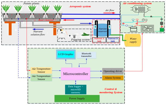
Figure 1.
The proposed aeroponic root chamber temperature conditioning architecture.
The root chamber air temperature is maintained by an air conditioning system. The conditioned air temperature circulates in a closed off-cycle to maintain the potato plant roots optimally absorbing the nutrient for healthy growth. The conditioned air temperature of the root chamber is provided by a refrigeration system. The refrigeration system is controlled by the automation and monitoring system through root chamber air temperature acquisition system using temperature sensors. The root chamber air temperature maintenance and control is the main focus of this research to achieve an essential potato plant growth environment.
2.3. The Root Chamber Air Circulation and Conditioning
The root chamber and air circulation aeroponic system design is shown in Figure 2. The root chamber dimensions are 15 × 0.5 × 0.5 m (L × W × H). The air flows from the refrigeration system through an air duct to the root chamber. The air distributed inside the root chamber thus flows returning to the refrigeration system through a return air duct. The air continuously circulates to maintain the root chamber temperature. The refrigeration system operates as long as the air temperature inside the root chamber has yet achieved the setting temperature. It maintains the air temperature and the air from the root chamber flows back to the refrigeration system through return air ducting. The air is conditioned by the refrigeration system according to a set temperature. Conditioned air supplied to the root chamber cycles continuously, going on to distribute air. The refrigeration system stops operating if the root chamber temperature achieves the setting temperature and re-starts if the root chamber temperature becomes higher than the setting temperature.
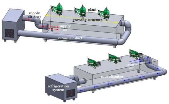
Figure 2.
The root chamber and air circulation diagrams.
2.4. The Air Conditioning System
The refrigeration system was designed considering it can maintain the root chamber temperature in the at 10 °C‒20 °C range. The refrigeration cycle (A–I) is shown in Figure 3.
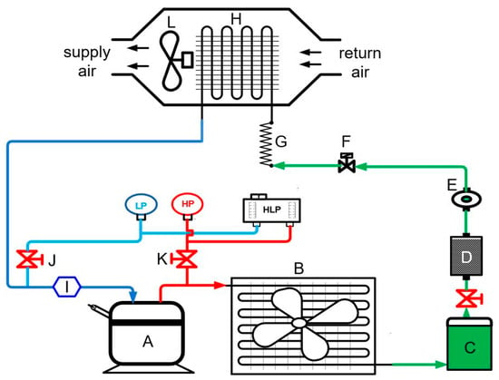
Figure 3.
Air conditioning diagram (A is the compressor, B is the condenser, C is the liquid receiver, D is the filter drier, E is the sight glass, F is the solenoid valve, G is the capillary tube expansion, H is the evaporator, I is the accumulator, J and K are manual valves, and L is the centrifugal fan).
The system uses vapor compression refrigeration to perform root chamber air conditioning and has the main components: compressor, condenser, evaporator, and thermal expansion valve. The vapor compression type is chosen due to its cooling capacity, efficiency, and coefficient of performance (COP) better than other refrigeration system types [28,29].
From the air conditioning design perspective, the root chamber and potato roots are defined as the cooling load. Therefore, the cooling load is derived into wall gain, product and wall infiltration loads. The wall gain load comes from all root chamber walls, the infiltration load comes from the root chamber roof (potato plant support structure) and the product load comes from the potato plant roots. The root chamber wall is designed using three material layers that consist of Styrofoam, plywood, and plastic, as shown in Figure 4.
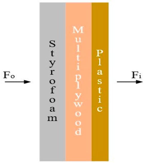
Figure 4.
The root chamber wall composition (Fo is convective heat transfer coefficient of the outer wall, Fi is the convective heat transfer of the inner wall).
With an overall coefficient wall heat transfer (U) of 0.352 W/m2∙°K (Fo = 22.7 W/m2∙°K, Fi = 9.37 W/m2∙°K), the root chamber volume of 3.75 m3, ambient temperature of 26 °C, root chamber temperature target of 15 ± 5 °C, mist nutrient temperature of 24 °C, infiltration rate of 3.25 L/s, air change factor of 0.044 kJ/L, and chilling time of 30 min, the total load capacity is then obtained at 2.736 kW (calculation using Hourly Analysis Program (HAP) E20 software).
The total load capacity is used to define the refrigeration system cooling capacity and choose the compressor capacity, condenser, evaporator and capillary tube expansion unit capacity.
2.5. The Control and Monitoring System
The root chamber temperature is maintained by the air conditioning system and controlling by automation system. The automation system is based on a microcontroller, as shown in Figure 5. The root chamber temperature is acquired using six temperature sensors placed in a distributed area inside the root chamber.
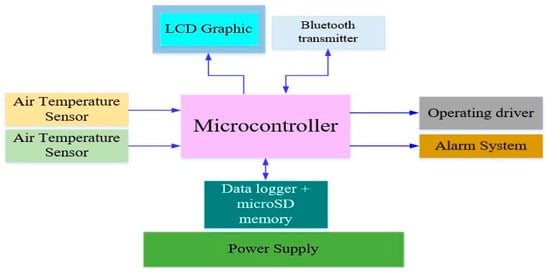
Figure 5.
The control and monitoring system diagram.
The temperature data is displayed on the liquid crystal display (LCD) graphic and recorded in memory using a data logger module for further processing. The refrigeration system is operated using an operating driver controlled by a microcontroller based on the comparison between the set temperature and the root chamber temperature. An alarm indicator performs notifications regarding the root chamber temperature threshold setting. A Bluetooth transmitter module is also provided in order to transfer data wirelessly to other terminal monitors (personal computer (PC), notebook, etc.).
2.6. System Implementation and Testing
2.6.1. The Air Conditioning System
The air conditioning system construction is shown in Figure 6. All main refrigeration system components were chosen according to the total load capacity design of the root chamber. The total load capacity is 2.736 kW, therefore, the refrigeration and air conditioning system components are described as shown in Table 1.
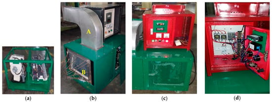
Figure 6.
The air conditioning system construction: (a) components assembly; (b) ducting construction (A is the supply air and B is the return air frame); (c) electrical wiring panel box; (d) electrical wiring panel.

Table 1.
The refrigeration system components.
All refrigeration and air conditioning components are assembled inside at compact box as shown in Figure 6a. The components are arranged so that the system is easy to maintain and integrate with the root chamber, especially for the supply and return air ducting installation. The construction and assembly follow the diagram as described in Figure 3. The supply air ducting is assembled on the box top while the return air frame is assembled to the left of the box, as shown in Figure 6b. An electrical wiring panel box also made and placed on the top of box where electrical circuit, control and monitoring devices installed as shown in Figure 6c. The panel box provides a supply air temperature indicator, voltage and current consumption meters, power indicator and on/off switch, and some switches and indicator lamps for system repairing purposes. Figure 6d shows the air conditioning system electrical wiring.
The refrigeration system operates using R404a refrigerant type. This refrigerant was chosen because it is environment friendly and non-flammable refrigerant [30]. The components of the refrigeration system are listed in Table 1.
The root chamber construction is shown in Figure 7. The root chamber top wall is a growing plant structure that separates the potato’s plants and roots. Its wall is composed of three material layers to minimize the ambient temperature infiltration and block the ambient light into the root chamber. The outer layer material is 50 cm of multi plywood as shown in Figure 7a. The middle layer material is 50 cm of Styrofoam as shown in Figure 7b, and the inner layer material is 0.8 cm of black colored plastic (Figure 7c). The root chamber top wall is made of 50 cm Styrofoam and covered with a silver colored plastic.
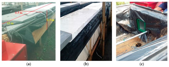
Figure 7.
The root chamber construction: (a) outer layer; (b) middle layer; (c) inner layer.
2.6.2. Control and Monitoring System
The control and monitoring device construction follows the diagram as described in Figure 5. The system uses the Arduino Uno R3 board as the main unit. This board uses ATmega328 microcontroller chip. Six thermocouple K-type modules from Adafruit were chosen to sense the root chamber temperature in six different locations. The sensor has a temperature sensing range between −200 °C and 1350 °C. The sensor accuracy is in the ±2 °C to ±6 °C range. It includes a signal amplifier connected with the Arduino board as shown in Figure 8a. A data logger shield with a real-time clock (RTC) module from Adafruit is used to record and store the temperature data in a microSD memory. The temperature data can also be displayed in an LCD shield kit with 20 × 4 Character display.
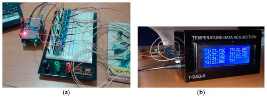
Figure 8.
The control and monitoring system: (a) sensor assembly; (b) the final design.
A Bluesmirf Gold Mate module from Sparkfun is chosen to support data transmission. This module enhances the control and monitoring system, transmitting data wirelessly to other data terminal recorders. It can transfer data in the 100 m range over open air. The Arduino board performs on/off control action using solid state relay (SSR). The SSR couples with the refrigeration system and turns on/off the refrigeration system according to the root chamber temperature which sense using thermocouples, while the alarm system implemented a buzzer sound and LED (light emitting diode) indicator.
The control and monitoring system operates using a wall power supply with a nominal output voltage of 9 V at 1 A. Figure 8b shows the control and monitoring system casing where all electronic components organize to fit with compact casing. The casing dimensions 20 × 12 × 10 cm and made using acrylic material.
The Arduino C code developed to perform control and monitoring actions in order to maintain the root chamber temperature. The code implemented based on the algorithm described as follows:
- InitializationSet temperature setting, temperature differential
- Read the temperature from six temperature sensors
- Display the temperature data on the LCD
- Record the temperature data into the memory
- Transmit the temperature data to the serial interface port
- Process and analyze all the temperature data
- If the temperature data more than (setting point + temperature differential) then turn off the SSRElse if the temperature data less than (setting point − temperature differential) then turn on the SSR
- Read the supply air temperature
- If the temperature more than 30 °C then turn on the buzzer and LED blinking in 3 s
- Else turn off the buzzer and LED.
2.6.3. System Integration
In order to build the complete system as described in Figure 1, the root chamber, air conditioning system, and control and monitoring system assembled as shown in Figure 9. The supply air ducting is installed to the inlet air side of the root chamber while the return air ducting is installed to the outlet air side of the root chamber as shown in Figure 9a. The supply air ducting isolated with isolating material to minimize heat transfer of the conditioned supply air to the environment.
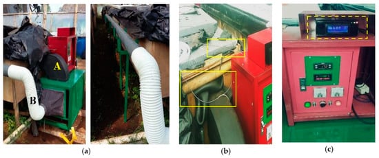
Figure 9.
The system integration: (a) air conditioning system (A is the supply air ducting and B is the return air ducting); (b) temperature sensors installation; (c) control and monitoring system.
After the ducting assembled with the root chamber, one temperature sensors put inside of supply air ducting and two temperature sensors put inside of the root chamber in different locations, respectively at 3 m and 12 m from the supply air inlet. The sensor installation is shown in Figure 9b. The control and monitoring system is assembled with the temperature sensors and the air conditioning system. The control and monitoring system is placed on top of the panel box, as shown in Figure 9c.
2.6.4. System Testing
Testing was performed to verify the developed system’s functionality and performance before the system is used for the experiment of mini-tuber potato seed cultivation. In this test, the supply air temperature was set at 17 °C and the temperature differential was set at ±4 °C. When the main power system is turned on, the refrigeration and air conditioning system were examined firstly to make sure it can provide conditioned supply air, as shown in Figure 10a. The compressor pressure indicators (LP and HP) and sight glass can be used to verify that the refrigerant is flowing according to the vapor compression refrigeration cycle, as shown in Figure 3. The refrigeration and air conditioning system worked according to the design as shown in Figure 10b. The temperature indicator shows that the supply air temperature can be maintained according to the temperature setting point at 17 °C. The system voltage and current consumption was at normal level as shown on the voltage and current indicator. This result also verified that the control system worked according to the design.
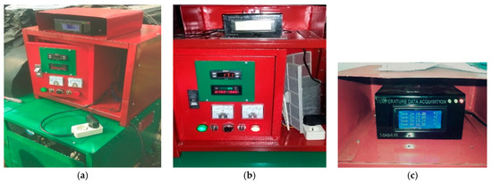
Figure 10.
Testing setup: (a) air conditioning system; (b) control panel; (c) data logger recording.
Figure 10c shows the root chamber temperature distribution sensed using six temperature sensors and displayed on the control and monitoring system LCD. The temperature sensors were placed inside of the root chamber in three different locations at 3 m, 7.5 m, and 12 m from the supply air inlet. The testing also verified that the temperature data was recorded continuously in real-time by the data logger in the microSD memory. The data file can be opened in Excel spreadsheet software as shown in Figure 11a and visualized in the graph as shown in Figure 11b for further data analysis. The testing results show the air conditioning system can maintain the root chamber temperature distribution ranging from 12 °C to 20 °C. That temperature range is needed for mini-tuber potato seed cultivation.

Figure 11.
The root chamber temperature: (a) data logger recording; (b) data trend.
2.7. Statistical Analysis
In order to figure out a reliable temperature treatment effect in seed potato cultivation yield using the aeroponic technique, analysis of variance (ANOVA) and t-test methods were used to analyze two groups of potato seed and stolon yield samples. Microsoft Excel Spreadsheet software developed by Microsoft Corporation was used to conduct statistical test. Those statistical technique can compare two groups of potato seed and stolon yield samples and depict how significantly different these group of samples from each other.
Another statistical calculation is eta squared (). The eta squared was used to calculate how much difference between the potato seed and stolon yield of the group of samples (unconditioned temperature and conditioned temperature) due to temperature treatment in the aeroponic root chamber. Eta squared is expressed as:
where SSbetween is the variance between group of samples, and SStotal is the total variance of group of samples.
3. Potato Seeds Cultivation Experimental
3.1. Preparation of Potato Seeds
In order to conduct field experiments, the mini-tuber potato seeds were initially sown in the husk fields by researchers at the Faculty of Agriculture, Universitas Winaya Mukti, Tanjungsari, Sumedang, Indonesia in early April 2020, as shown in Figure 12a. The mini-tuber potato seed was chosen in this experiment is the potato seed G0 Granola L as shown in Figure 12b.
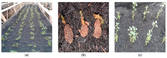
Figure 12.
Potato seeds: (a) seeding; (b) tuber; (c) potential plant.
Potato seed preparation on husks is carried out around two months to obtain seeds that have the potential to be cultivated using the aeroponic system. Potential plant seeds are those that have dry leaves, not exposed to pests and have healthy stems with a height of about 20 cm as shown in Figure 12c.
3.2. Experimental Procedure
Three root chambers were prepared for seed potato cultivation as shown in Figure 13. The root chamber placed in the semi greenhouse without environmental condition control (temperature, humidity).
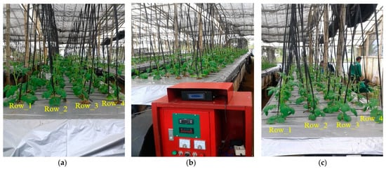
Figure 13.
The root chamber preparation: (a) unconditional temperature (root chamber_1); (b) conditional temperature (root chamber_2); (c) unconditional temperature (root chamber_3).
There are two root chambers with unconditional temperature (root chamber_1 and root chamber_3) as shown in Figure 13a,c, and one root chamber with conditional temperature (root chambar_2) as shown in Figure 13b. The root chamber_2 temperature will be maintained at 15 °C with the temperature differential at 5 °C, while the temperature in the other root chamber is only monitored and recorded by the data logger. The healthy potato seed from seed sown put on the growing structure of Aeroponics root chamber with spacing among other plants is 25 cm and composed of four rows of the potato plant. The potato seed roots are suspended below the root chamber growing structure. In order to minimize the ambient temperature infiltration into the root chamber, the growing structure was wrapped with the silver color plastic. The nutrient solution is sprayed onto the plant roots by the fogging system every 10 min for 30 s. The mini-tuber potato seeds are harvested in three months.
3.3. The Potato Plant Growing
The field experiment was conducted in the garden laboratory of the Faculty of Agriculture, Universitas Winaya Mukti, Tanjungsari, Jln. Raya Bandung-Sumedang km 29, Indonesia with altitude of 850 m.a.s.l. The general environment conditions were as follows: the relative humidity and ambient temperature are fluctuated (24 °C–29° C, 70%–90%), the average relative humidity and temperature respectively are 80% and 26 °C, and the rainfall is bimodal. The experiment was started on June 2020.
The data sample of root chamber temperature is shown in Figure 14. Temp_1-Temp_2, Temp_3-Temp_4, and Temp_5-Temp_6, respectively, are root chamber_1 temperature, root chamber_2 temperature and root chamber_3 temperature. The temperature data samples of root chambers were recorded by data logger on 22–23 June 2020 at 20.35 to 06.50 (Figure 14a) and on 27–28 June 2020 at 21.03–07.21 (Figure 14c).
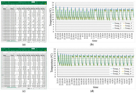
Figure 14.
The root chamber temperature data sample: (a) data logger recording; (b) data trend (22–23 June 2020 at 20.35–06.50); (c) data logger recording; (d) data trend (27–28 June 2020 at 21.03–07.21).
4. Discussion
According to the temperature data trend graph as described in Figure 14b,d, the temperature of root chamber_1 and root chamber_3 (unconditional chambers as shown in Figure 15) decreased from 23 °C to 20 °C because the environment temperature also has trend decreasing in the night until morning. This temperature influenced the nutrient solution temperature that sprayed into the root chambers. Therefore, the root chamber temperature was decreasing. While the air conditioning system maintained the chamber_2 temperature (conditional chamber as shown in Figure 15) at around 15 °C with the temperature differential at 3 °C (Temp_3, Temp_4).
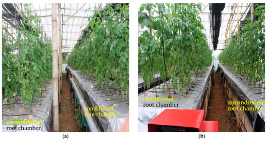
Figure 15.
Potato plants growing comparison: (a) root chamber with unconditional temperature (left) and root chamber with conditional temperature (right); (b) root chamber with conditional temperature (left) and root chamber with unconditional temperature (right).
To confirm the mini-tuber potato seed yield cultivated using aeroponics, the tuber seed yield in the three root chambers was observed in the second month of cultivation period from three months of harvesting period. The observation was conducted at the short time to prevent bacteria contamination from the ambient air and minimize sunlight exposure to the tuber seed yield. The mini-tuber potato seed yield resulting from the field experiment in two months are shown in Figure 16 and Figure 17.
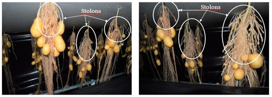
Figure 16.
Seed potatoes cultivation in the root chamber with conditional temperature (root chamber_2).
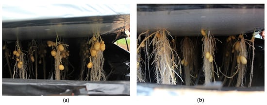
Figure 17.
Seed potatoes cultivation in the root chamber with unconditional temperature: (a) root chamber_1; (b) root chamber_3.
This field experiment shows the significant effect of root chamber temperature conditioning to the mini-tuber potato seed cultivation. The number of stolons produced in the root chamber with conditional temperature (Figure 16) was more than the number of seed potatoes cultivated in the root chamber with unconditional temperature (Figure 17).
In other words, the root chamber potato seed cultivation under optimal temperature has the potential to produce many potato seed tubers. The stolons arise on the potato plant roots and the stolon ends will swell to form the potato tubers. In this field experiment, the root chamber optimal temperature ranged from 10 °C to 20 °C. The number of potato seeds and stolon yield both in unconditioned and conditioned temperatures of aeroponic root chambers is shown in Table 2.

Table 2.
Number of potato seeds and stolon yield from potato plant roots.
The summary of samples that analyzed by one-way ANOVA method is shown in Table 3. Each group of samples (unconditioned temperature and conditioned temperature) has same number of sample (12) and unequal variances.

Table 3.
Summary of potato seed and stolon yield data.
The one-way ANOVA test was chosen because the group of samples come from single population, and analyzed the sample with alpha level (α) = 0.05 (standard hypothesis test), and the test result is shown in Table 4.

Table 4.
Statistical analysis result of ANOVA method.
From Table 4, the F-statistic value (F = 76.15) is more than the F-critical value (F crit = 4.30), therefore the null hypothesis is rejected. In other word, two group of samples (unconditioned temperature and conditioned temperature) are significantly different.
Whereas for the t-test result using two-sample assuming unequal variances is shown in Table 5. Two-sample assuming unequal variances was chosen because the group of samples have different variance. This test is also used to compare the means of two group of samples in Table 2. The test result can determine whether the temperature treatment of the root potato chamber actually has an effect on the potato seed and stolon yield.

Table 5.
Statistical analysis result of t-test method.
This t-test also used alpha level (α) = 0.05 to analyze the group of samples in Table 2. From Table 5, the p-value (P (T <= t) two-tail = 4.50 × 10⁻⁸) of the group of samples (unconditioned temperature and conditioned temperature) is less than the alpha level (0.05). This means that the group of potato seeds and stolon yield in the unconditioned temperature and the group of potato seeds and stolon yield in the conditioned temperature have less than a 5% chance of belonging to the same population. Two groups of samples have extremely different populations. In other word, the temperature treatment in the root potato chamber has a significant effect to improve the potato seed and stolon yield.
With Equation (1), the eta square of the samples in Table 2 is:
Hence, 77% of difference the potato seed and stolon yield of the group of samples (unconditioned temperature and conditioned temperature) is due to temperature treatment in potato root aeroponic chamber.
5. Conclusions
The aeroponics root chamber temperature conditioning method was applied in a mini-tuber potato seed cultivation field experiment. Potato seed tuber yield was improved. The root chamber temperature conditioning produced a significant effect on mini-tuber potato seed cultivation using aeroponics. The field experiment results revealed the optimal root chamber temperature treatment increased mini-tuber potato seed tuber yield (up to 77%) compared with mini-tuber potato seed cultivation in the unconditioned root chamber. The root chamber maintained potato roots in the 10 °C–20 °C temperature range.
Author Contributions
Conceptualization: Y.-D.K. and C.B.D.K.; methodology: C.B.D.K. and Y.-D.K.; formal analysis: T.S. and C.A.; investigation: T.S. and C.A.; supervision: C.B.D.K. and Y.-D.K.; resources: Y.-D.K.; writing—original draft preparation: T.S. and C.A.; writing—review and editing: C.B.D.K. and Y.-D.K. All authors have read and agreed to the published version of the manuscript.
Funding
This research funding by the Ministry of Science and Technology of Taiwan (MOST: 109-2622-E-167-014-CC2).
Data Availability Statement
The data presented in this study are available on the request from the corresponding author.
Acknowledgments
The authors would like to thank Ministry of Science and Technology of Taiwan for funding support. The authors thank the Refrigeration, Air Conditioning and Energy Engineering Department of National Chin-Yi University of Technology, Taiwan for support in the system design. The authors also thank the Refrigeration and Air Conditioning Engineering Department of Politeknik Negeri Bandung, Indonesia for their help in conducting testing and experiments activities.
Conflicts of Interest
The authors declare no conflict of interest.
References
- Data Lima Tahun Terakhir. Available online: https://www.pertanian.go.id/home/?show=page&act=view&id=61 (accessed on 15 May 2020).
- Mulyono, D.; Syah, M.J.A.; Sayekti, A.L.; dan Hilman, Y. Kelas Benih Kentang (Solanum tuberosum L.) Berdasarkan Pertumbuhan, Produksi, dan Mutu Produk. J. Hortic. 2017, 27, 209–216. [Google Scholar] [CrossRef]
- Correa, R.M.; Pinto, J.E.B.; Pinto, C.A.B.P.; Faquin, V.; Reis, E.S.; Monteiro, A.B.; Dyer, W.E. A comparison of potato seed tuber yields in beds, pots and hydroponic systems. Sci. Hortic. 2008, 116, 17–20. [Google Scholar] [CrossRef]
- Ritter, E.; Angulo, B.; Riga, P.; Herran, C.; Relloso, J.; Jose, M.S. Comparison of hydroponic and aeroponic cultivation systems for the production of potato minitubers. Pot. Res. 2001, 44, 127–135. [Google Scholar] [CrossRef]
- Chiipanthenga, M.; Maliro, M.; Demo, P.; Njoloma, J. Potential of aeroponics system in the production of quality potato (Solanum tuberosum L.) seed in developing countries. Afr. J. Biotechnol. 2012, 11, 3993–3999. [Google Scholar] [CrossRef]
- Chindi, A.; Giorgis, G.W.; Solomon, A.; Tessama, L.; Negash, K. Rapid Multiplication Techniques (RMTs): A tool for the production of quality seed potato (Solanum tuberosum L.) in Ethiopia. Asian J. Crop Sci. 2014, 6, 176–185. [Google Scholar] [CrossRef]
- Mateus-Rodríguez, J.R.; de Haan, S.; Andrade-Piedra, J.L.; Maldonado, L.; Hareau, G.; Barker, I.; Chuquillanqui, C.; Otazú, V.; Frisancho, R.; Bastos, C.; et al. Technical and economic analysis of aeroponics and other systems for Potato mini-tuber production in Latin America. Am. J. Potato Res. 2013, 90, 357–368. [Google Scholar] [CrossRef]
- Muthoni, J.; Kabira, J. Multiplication of seed potatoes in a conventional potato breeding programme: A case of Kenya’s national potato programme. Austral. J. Crop Sci. 2014, 8, 1195–1199. [Google Scholar]
- Dianawati, M.; Ilyas, S.; Wattimena, G.A.; Susila, A.D. Produksi Umbi Mini Kentang Secara Aeroponik Melalui Penentuan Dosis Optimum Pupuk Daun Nitrogen. J. Hort. 2013, 23, 47–55. [Google Scholar] [CrossRef]
- Buckseth, T.; Sharma, A.K.; Pandey, K.K.; Singh, B.P.; Muthuraj, R. Methods of pre-basic seed potato production with special reference to aeroponics—A review. Sci. Hortic. 2016, 204, 79–87. [Google Scholar] [CrossRef]
- Mbiyu, M.W.; Lung’aho, C.; Otieno, S.A.; Nyongesa, M.W.; Muchui, M.N.; Ogemma, J.N. Performance of five potato varieties with regards to growth and production of minitubers under an aeroponic system in central highlands of Kenya. Afr. J. Agric. Res. 2018, 13, 366–378. [Google Scholar] [CrossRef]
- Oraby, H.; Lachance, A.; Desjardins, Y. A low nutrient solution temperature and the application of stress treatments increase potato mini-tubers production in an aeroponic system. Am. J. Potato Res. 2015, 92, 387–397. [Google Scholar] [CrossRef]
- Rykaczewska, K. The potato minituber production from microtubers in aeroponic culture. Plant Soil Environ. 2016, 62, 210–214. [Google Scholar] [CrossRef]
- Tessema, L.; Chindi, A.; Giorgis, G.W.; Solomon, A.; Shunka, E.; Seid, E. Determination of nutrient solutions for potato (Solanum tuberosum L.) seed production under aeroponics production system. Open Agric. 2017, 2, 155–159. [Google Scholar] [CrossRef]
- Tierno, R.; Carrasco, A.; Ritter, E.; Galarreta, J.I.R. Differential growth response and mini-tuber production of three potato cultivars under aeroponics and greenhouse bed culture. Am. J. Potato Res. 2014, 91, 346–353. [Google Scholar]
- Wang, C.-C.; Wang, X.-Y.; Wang, K.-X.; Hu, J.-J.; Tang, M.-X.; He, W.; Zaag, P.V. Manipulating aeroponically grown potatoes with gibberellins and calcium nitrate. Am. J. Potato Res. 2018, 95, 1–11. [Google Scholar] [CrossRef]
- Wang, K.; He, W.; Ai, Y.; Hu, J.; Xie, K.; Tang, M.; Wang, Y.; Zaag, P.V. Optimizing seed potato production by aeroponics in China. Philipp. J. Crop Sci. 2017, 42, 69–74. [Google Scholar]
- Silva Filho, J.B.; Fontes, P.C.R.; Cecon, P.R.; McGiffen, M.E., Jr. Evaluation of “UFV aeroponic system” to produce basic potato seed minitubers. Am. J. Potato Res. 2018, 95, 443–450. [Google Scholar] [CrossRef]
- Mbiyu, M.W.; Muthoni, J.; Kabira, J.; Elmar, G.; Muchira, C.; Pwaipwai, P.; Ngaruiya, J.; Otieno, S.; Onditi, J. Use of aeroponics technique for potato (Solanum tuberosum) minitubers production in Kenya. J. Hortic. For. 2012, 4, 172–177. [Google Scholar]
- Lakhiar, I.A.; Gao, J.; Syed, T.N.; Chandio, F.A.; Buttar, N.A. Modern plant cultivation technologies in agriculture under controlled environment: A review on aeroponics. J. Plant Interact. 2018, 13, 338–352. [Google Scholar] [CrossRef]
- Calori, A.H.; Factor, T.L.; Feltran, J.C.; Watanabe, E.Y.; Moraes, C.C.; Purquerio, L.F.V. Electrical conductivity of the nutrient solution and plant density in aeroponic production of seed potato under tropical conditions (winter/spring). Bragantia 2017, 76, 23–32. [Google Scholar] [CrossRef]
- Abdullateef, S.; Bohme, M.H.; Pinker, I. Potato minituber production at different plant densities using an aeroponic system. Acta Hortic. 2012, 927, 429–436. [Google Scholar]
- Hubick, K.T.; Drakeford, D.R.; Reid, D.M. A comparison of two techniques for growing minimally water-stressed plants. Can. J. Botany. 1982, 60, 219–223. [Google Scholar] [CrossRef]
- Soffer, H.; Burger, D.W. Effects of dissolved oxygen concentration in aero-hydroponics on the formation and growth of adventitious roots. J. Am. Soc. Hortic. Sci. 1988, 113, 218–221. [Google Scholar]
- Wagner, R.E.; Wilkinson, H.T. An aeroponics system for investigating disease development on soybean taproots infected with Phytophthora sojae. Plant. Dis. 1992, 76, 610–614. [Google Scholar] [CrossRef]
- Sylvia, D.M.; Hubbel, D.H. Growth and sporulation of vesicular-arbuscular mycorrhizal fungi in aeroponic and membrane systems. Symbiosis 1986, 1, 259–267. [Google Scholar]
- Zobel, R.W.; del Tredici, P.; Torrey, J.G. Method for growing plants aeroponically. Plant Physiol. 1976, 57, 344–346. [Google Scholar] [CrossRef]
- Yeom, J.; Shannon, M.A.; Singh, T. Micro-Coolers. In Reference Module in Materials Science and Materials Engineering, 1st ed.; Elsevier: Amsterdam, The Netherlands, 2017. [Google Scholar] [CrossRef]
- Liang, K.; Li, Z.; Chen, M.; Jiang, H. Comparisons between heat pipe, thermoelectric system, and vapour compression refrigeration system for electronics cooling. Appl. Them. Eng. 2019, 146, 260–276. [Google Scholar] [CrossRef]
- Heredia-Aricapa, Y.; Belman-Flores, J.M.; Mota-Babiloni, A.; Serrano-Arellano, J.; García-Pabón, J.J. Overview of low GWP mixtures for the replacement of HFC refrigerants: R134a, R404A and R410A. Int. J. Refrig. 2020, 111, 113–123. [Google Scholar] [CrossRef]
Publisher’s Note: MDPI stays neutral with regard to jurisdictional claims in published maps and institutional affiliations. |
© 2021 by the authors. Licensee MDPI, Basel, Switzerland. This article is an open access article distributed under the terms and conditions of the Creative Commons Attribution (CC BY) license (https://creativecommons.org/licenses/by/4.0/).