Article

The Experimental Timber–UHPC Composite Bridge

1
Klokner Institute, Czech Technical University in Prague, 166 08 Prague, Czech Republic
2
Faculty of Civil Engineering, Czech Technical University in Prague, 166 29 Prague, Czech Republic
*
Author to whom correspondence should be addressed.
Sustainability 2021, 13(9), 4895; https://doi.org/10.3390/su13094895
Submission received: 31 January 2021 / Revised: 14 April 2021 / Accepted: 21 April 2021 / Published: 27 April 2021

Abstract

:
This paper describes the development of an innovative timber–concrete composite bridge system and especially focuses on the evaluation of the load tests of an experimental bridge structure. The load-bearing structure was designed as glue-laminated timber beams connected with only 60-mm-thick precast bridge deck segments made of ultra-high-performance concrete (UHPC). To verify the production details and behavior of the designed structure, we built a full-scale experimental structure and performed a load test. The load test was arranged as a four-point bending test. First, we performed the overall load test until failure. Some bridge deck segments were consequently cut from the structure in order to run further load tests of the bridge deck in the transversal direction. The results of the experiments were evaluated in detail and compared with analytical calculations.

1. Introduction

The current tendency for an efficient use of resources includes sustainable material management and production with minimal impact on the environment. The effort to use renewable materials leads to a more frequent application of timber for load-bearing structures. Composite bridge structures made of timber and concrete represent an environmental benefit because they allow the application of timber, which is a renewable natural material; effectively use the properties of both materials (timber and concrete); and provide interesting architectonic values. The combination of timber and concrete provides a number of advantages, especially compared to traditional timber structures; e.g., a concrete bridge deck protects the timber beams against direct weather influences.
The topic of TCC bridge structures is extensive because of the many possibilities of their application. These structures include various different composite materials, and they have specific static behavior given by their semi-rigid connection. A comprehensive research of timber–concrete composite structures was carried out, e.g., by Ceccoti [1], Yeoh [2], Rodriguez [3], Simon [4], and others. A number of timber–concrete composite (TCC) bridges have already been realized in recent decades in the world, e.g., the Birkberg Bridge in Germany, the Ragoztobel Bridge in Switzerland, the Vihantasalmi Bridge in Finland, the Quianos Bridge in Portugal, and others [3]. Based on the experience with their application, it has been shown that timber–concrete composite bridges can be a competitive alternative to commonly used reinforced concrete and steel structures.
The possibilities of using precast bridge deck segments made of UHPC for TCC bridge structures were analyzed in our research program. Timber has a favorable weight-to-strength ratio (e.g., commonly used grade C24 timber has an approximately two times more favorable weight-to-strength ratio in bending than grade S235 steel). UHPC makes it possible to design thin slabs. A bridge deck made of UHPC adds much less dead weight to the timber structure compared with a conventional standard-strength concrete bridge deck. When using a precast UHPC bridge deck, the effects of creep and shrinkage of concrete are significantly reduced. Research in the field of development of special coupling elements for timber–concrete composite structures with prefabricated concrete slab was realized, e.g., by Kuklík [5], Fragiacomo [6], Crocetti [7], and others. The prefabrication represents the benefits of generally higher structure quality and higher construction speed. In the case of timber–concrete composite structures, the reduction in the wet process on-site is an especially important benefit. There is no need to use falsework and formwork on-site or no need to use a lost formwork that increases the structure’s dead weight.
UHPC is still quite a new material, and design standards have been not published in the Czech Republic yet (only some methodologies [8]), even though the standards for UHPC have already been in place abroad for a long time, e.g., AFGC [9], Betonkalender [10], and others.
According to LCA case studies, e.g., Hájek [11], timber–UHPC composite structures show a lower GWP environmental impact than traditional reinforced concrete structures in the field of building construction. No similar study has been performed for bridge structures.
The optimization of TCC bridge structures using the application of a precast bridge deck made of UHPC was studied in our research program. We studied computational analysis of TCC structures, design and analysis of a specific type of coupling elements, and design of a precast bridge deck made of UHPC in detail. There have been a number of experiments carried out at the Klokner Institute of CTU in Prague under the support of the Technology Agency of the Czech Republic (TACR).

2. Materials and Methods

2.1. Research Program

The first part of our research program was focused on the verification of mechanical characteristics of the proposed shear connection system. The shear connection is carried out by notches made of steel plates embedded in timber beams supplemented with welded shear dowels (headed studs). A similar solution was already used, e.g., at the bridge over the river Wipper in Germany (see Fragiacomo [12]). The precast segments are provided with slots for the shear dowels, into which UHPC is poured after placing of the deck segments on the timber beams. The application of UHPC to joints has already been successfully used in steel–concrete composite structures (see Vítek [13,14]). The test specimens for the push-out shear test were composed of two identical precast UHPFRC slabs and a timber beam with connectors placed in the middle between them (see Figure 1b). The description of this connection system, experiments, and their evaluation are presented in Holý [15,16,17].
Because UHPC is still a relatively new material in the Czech Republic and no standards have been issued yet, another part of the experiments was focused on the verification of the load-bearing capacity of thin slabs made of a local mixture of UHPC. The flexural tensile strength of UHPC is not an intrinsic material property (see in more detail, e.g., Duque [18] and Kolísko [19]). Various bending tests for determining the flexural strength of UHPC were performed. The results of the tests on special test specimens (see Figure 1a) were compared with the results of bending tests according to different valid standards in the Czech Republic. Performed experiments and their evaluation are presented in Holý [20,21].
The last part of our research program was devoted to the production and testing of the experimental structure, which is described in more detail later in this article.

2.2. Material Characteristics

Ultra-high-performance concrete is a promising material, and its favorable material properties allow one to design thin structures. The developed UHPC mixture consists of CEM II 52.5 N cement, a fine aggregate with a maximum size of 2 mm; slag; silica fume; and steel fibers (0.2 mm thick and 13 mm long). For some details about the development of a local mixture in the Czech Republic, see Kolísko [22]. The volume of the fibers is 1.5%. Some laboratory tests were executed on cubes, cylinders, and beams to determine the basic material properties of UHPC (see Table 1). Some interesting structures of footbridges using this mixture of UHPC were already designed and tested at the Klokner Institute, e.g., the footbridge with double curvature (Kolísko [23] and Kněž [24]).
The load-bearing beams were made of glued laminated timber of class Gl24h. The timber class Gl24h was chosen mainly due to its good availability in the local market (higher-strength classes are less available in the Czech Republic). The load test of the experimental structure was supplemented by material tests of wood to determine moisture and density. Density is the most important physical characteristic of wood, as most of its mechanical properties depend on it. The following table compares the mean values of density according to the standard ČSN EN 14 080 [25] and the density obtained from material tests.
The mean value of density was determined for 16 specimens, the coefficient of variation was 15%, and standard deviation was 62.7. It can be seen from Table 2 that the used timber disposed of a similar mean value of density as the standard value of class Gl24h. The material properties of timber were therefore considered by standard values. The selected important mechanical material properties are listed in Table 3.

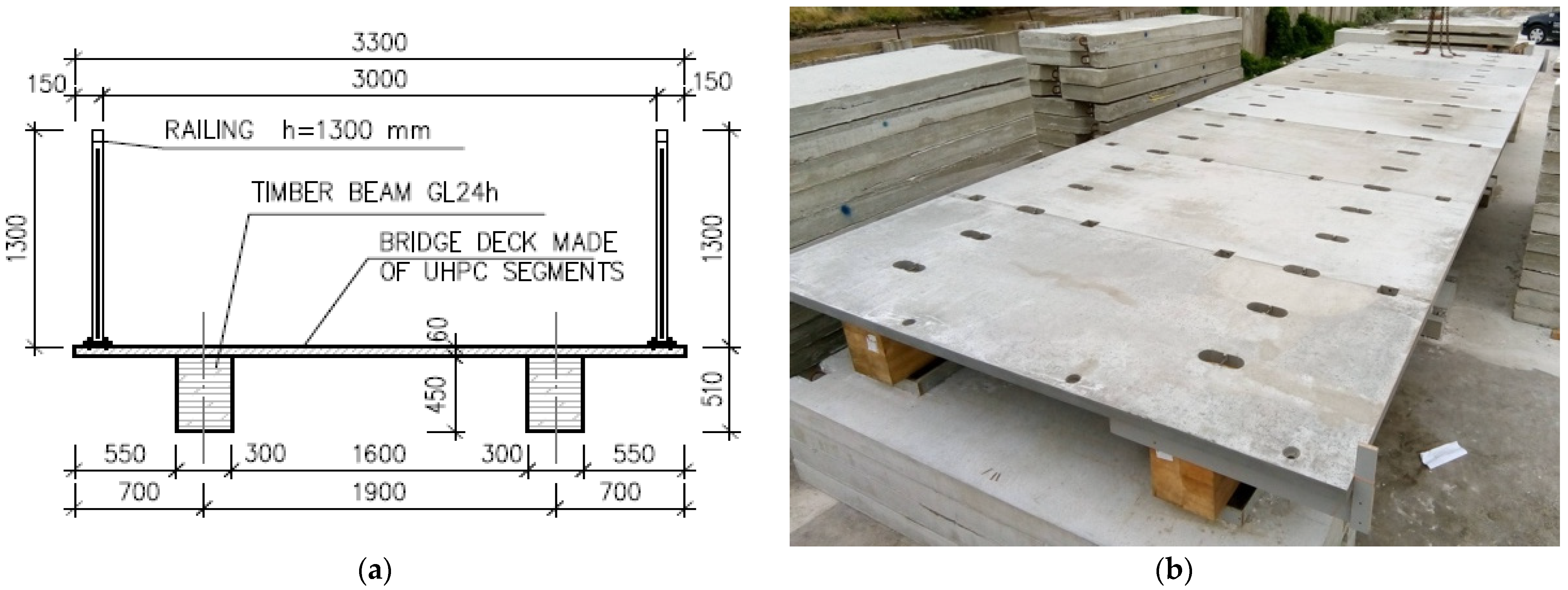
2.3. Experimental Structure

An experimental full-scale bridge structure was produced to verify some manufacturing details and the load-bearing capacity. After the overall load test was performed, some bridge deck segments were cut from the structure and subsequent load tests of the bridge deck in the transverse direction were carried out and compared with the analytical prediction.
The design of the bridge system assumed that the bridge will be designed as a footbridge for pedestrians and cyclists and the crossing of rescue or maintenance vehicles up to 3.5 t and that the clear width between railings will be 3.00 m. The timber–concrete composite bridge structure was designed on a scale of 1:1 as a simply supported beam with a 10.24 m length, a theoretical span of 9.50 m, and a total width of 3.30 m. These variables were used to design an optimized bridge system—it will be possible to universally apply the given bridge system for different spans (ca. 10–25 m). The load-bearing structure consisted of 2 timber beams at an axial distance of 1900 mm, with a rectangular cross section of 450 mm height and 300 mm width made of glue-laminated GL24h class timber and connected with bridge deck segments of constant 60 mm thickness made of UHPC (see Figure 2).
The bridge deck was made of transverse prefabricated segments with typical system length 1.5 m and width 3.30 m. Three types of bridge deck segments were designed: typical panels—type N; end panels—type K; and vertical panels on the end—type Z (see Figure 3). The vertical panels were designed to protect timber beams from water running from the bridge ends. For the same reason, some grooves on the bridge deck cantilevers were designed. The bridge deck segments were reinforced with mesh using a 20 mm concrete cover. The precast bridge deck segments were produced with slots for shear connectors. For the handling of bridge deck segments, reinforcing bars passing through the slots in the segments were designed.
The shear connection was carried out by steel plates with welded headed studs, which were fixed to a timber beam by a pair of timber screws (see Figure 4). The timber screws were designed to transfer a vertical tensile force, which could occur, e.g., due to temperature load. The slots were designed with rounded corners to prevent stress concentration in corners. The coupling elements were placed at a distance of 500 mm in the region of the N panels and at a distance of 455 mm in the region of the K end panels. The coupling elements were designed of 2 types with different heights of the steel plate (i.e., height of notch)—near the supports with a height of 30 mm and in a span with a height of 20 mm.
The bridge deck segments were connected using epoxy adhesive and special screw connections, which helped the epoxy adhesive properly harden in the joints. The screw connections were also designed to transmit tensile forces in the joints from the temperature load. After installing all panels, grouting was carried out in the slots for connectors and for screw connections.
The erection of the test bridge structure was realized in July and August 2019. A total of 9 bridge deck segments were produced. A custom formwork was used for each panel type. A partly steel formwork was used to ensure constant dimensions of panels.
During the construction phase, there were temporary supports placed under the timber beams in thirds of the span. First, the Z-type vertical panels were installed on the ends of timber beams (the vertical panels were fixed to the timber beams via special mounting brackets). The assembly of the bridge deck segments proceeded from one end to the other. A K-type end panel was placed and connected to the vertical panel by screw connections. The N-type epoxy adhesives were applied to the front faces of two bridge deck segments before the installation of every following bridge deck segment. After placing the new panel next to the previous one, the panels were fastened together using screw connections, which helped to properly harden the epoxy adhesive in the joint. After installing all panels, grouting was carried out in the slots for connectors and screw connections. The temporary supports were removed 14 days after the application of grouting.

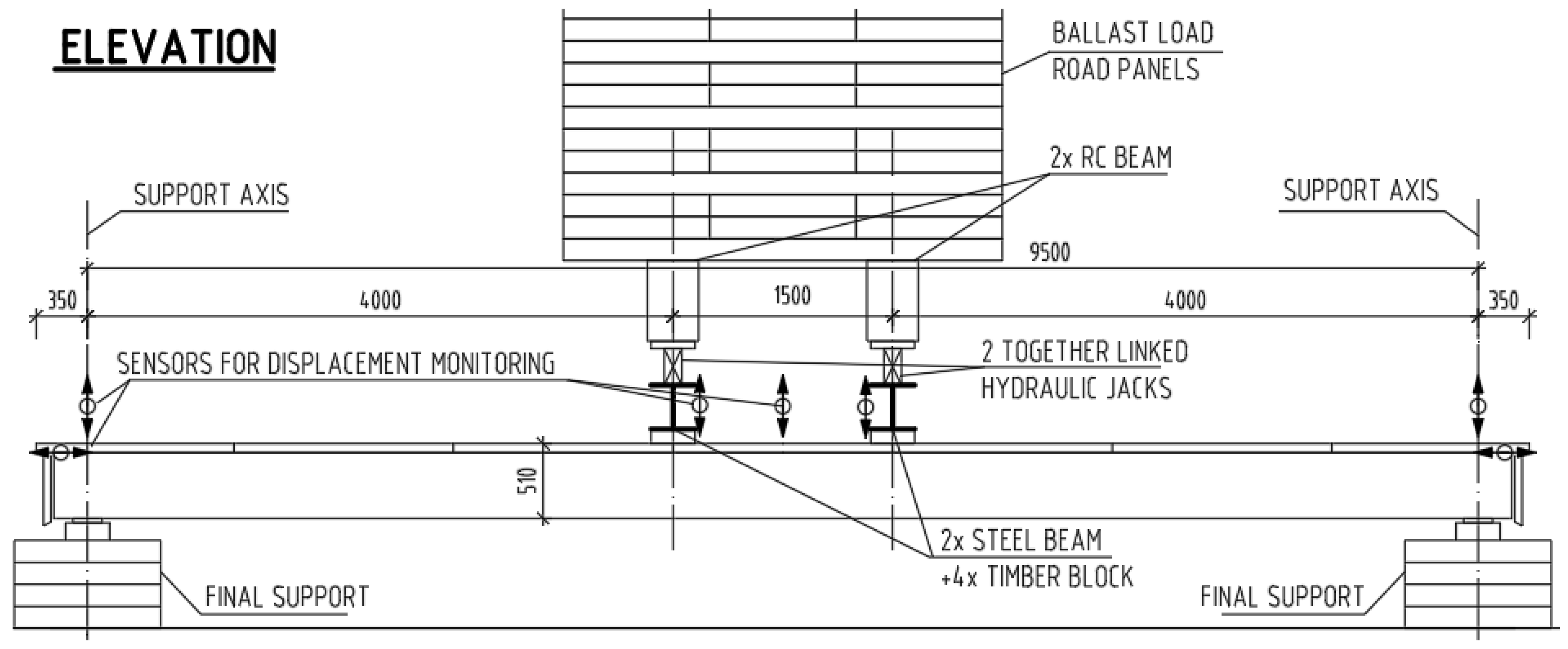
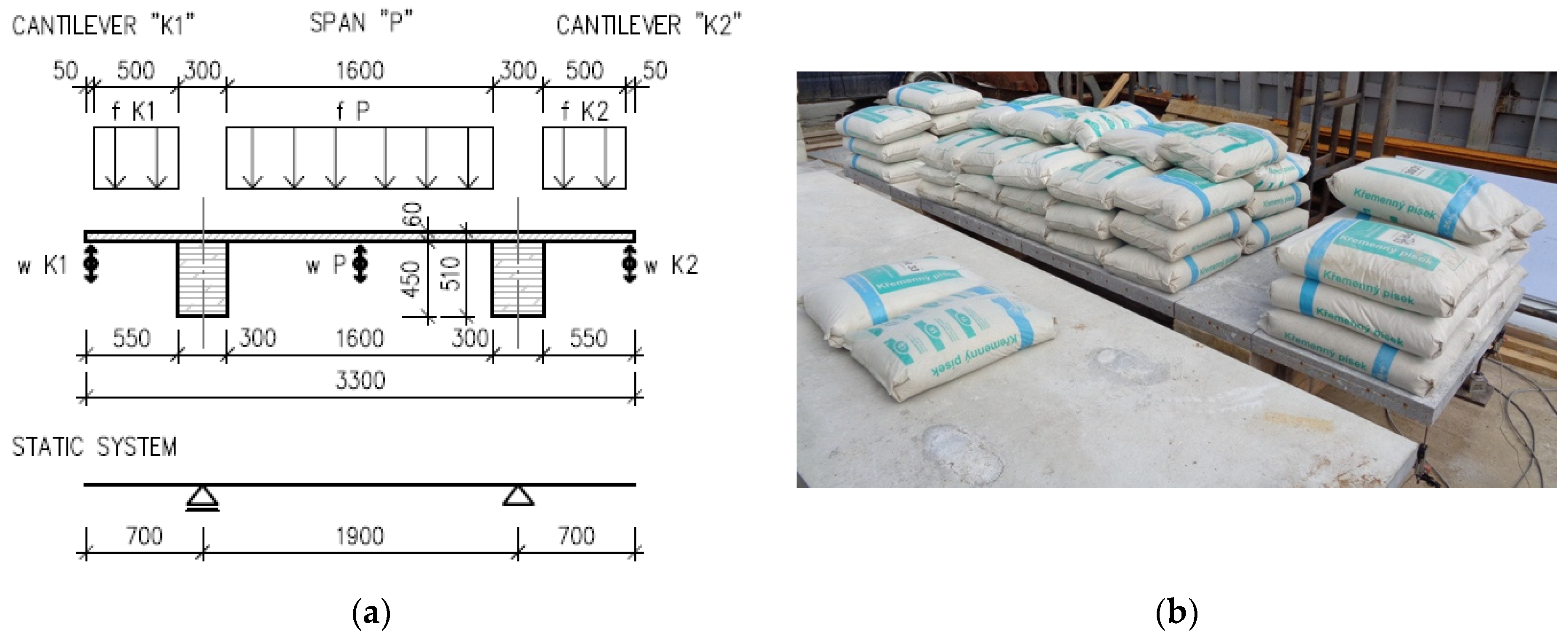
2.4. Load Test of the Experimental Structure

The load test was carried out in August 2019. The load test of the experimental bridge structure was performed by four-point bending until failure. The test setup is shown in Figure 5. The span was 9.5 m, and the load was applied symmetrically at a distance of 4 m from the supports to the timber beams via 2 hydraulic cylinders linked together and supported by reinforced concrete beams with ballast load from road panels.
The vertical displacement of the timber beam was monitored with 8 point sensors—2 sensors placed in the middle of the span above both timber beams, 4 sensors placed at the loading points, and 2 sensors placed in support axes. The slips between the bridge deck and timber beams were also monitored—4 sensors were placed on the ends of both timber beams, and the steel plates were equipped with marks, in addition. The force was measured on the hydraulic cylinder.
The loading was controlled by force and was carried out in several phases. In the first phase, the structure was 10 times cyclically loaded and unloaded with a force of 2 × 34 kN. This load should generate the maximum shear force corresponding to a frequent load combination. This cyclic loading was performed to press the contact surface of the notches. In the second phase, the structure was loaded with a force of 2 × 44.5 kN. This load should generate the bending moments corresponding to a characteristic load combination (thermal load not included). In the third phase, the structure was loaded with force 2 × 67.1 kN. This load should generate the bending moments corresponding to the design load combination in ULS 6.10 according to ČSN EN 1990 (thermal load not included). In the last stage, the structure was loaded by gradual load increase until failure.
Before the load test was performed, the forces on the cylinders corresponding to the design load combinations according to ČSN EN 1990 [26] for the final footbridge were determined (see Table 4 and Table 5). Analysis of the timber–concrete composite structure with a semirigid connection was performed using lattice girder approximation with rigid arms simulating the composite action according to [27]. The computational model of the structure was created in SCIA Engineer software (see Figure 6). Timber beams were modeled as bar elements, and the bridge deck was modeled as a slab. The coupling elements were simulated using rigidly connected arms, with bending stiffness calculated according to [27]. The arms were hinge-connected in the joint between the coupled parts. At half the distance between the coupling elements, the hinge-connected rigid struts were modeled. These struts ensure the same deflection of both coupled parts.

3. Results

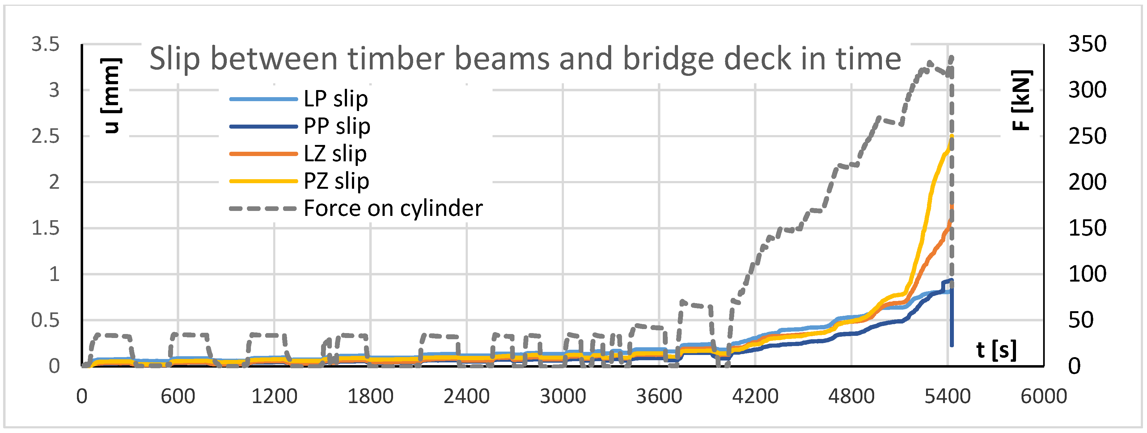
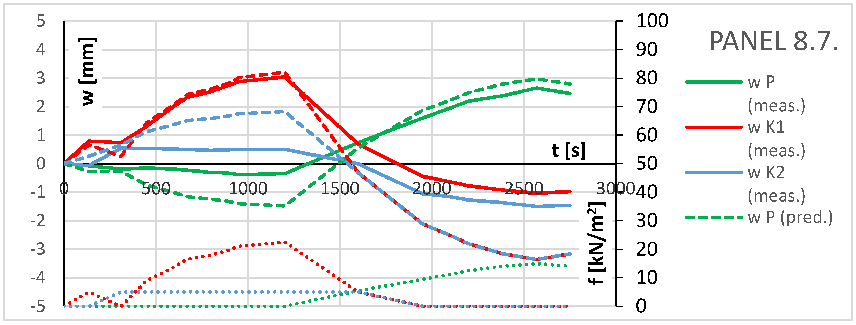
3.1. Load Test on the Experimental Structure

The records from the load test are shown in Figure 7, Figure 8 and Figure 9. The development of load and deflection in the middle of the span in time (test procedure) are shown in Figure 7. Good immediate dependance of these two parameters was shown during the loading process until failure. At the end, there was a significant drop in the loading force, with a significant increase in deflection. The same characteristic is shown in Figure 8, where a development of load and slip between bridge deck and timber beam is shown over several time points. The correlation between load and displacement (slip) is still evident. In addition, a significant increase in slips after the maximum loading force was reached was observed. The behavior of the structure corresponding to the characteristic load combination was linearly elastic, and no plastic deformation was observed after unloading. The theoretical load corresponding to the ultimate limit state (calculated with characteristic values of material properties) was determined by a load of 2 × 130 kN.
The experimental bridge structure reacted elastically up to a load of approx. 2 × 270 kN (see Figure 7 and Figure 9), and then the nonlinear increase in slip between the Z timber beam and the bridge deck occurred (see Figure 8).
The experimental structure failure occurred by a tensile failure of the P timber beam at a load of 2 × 330 kN (see the damaged timber beam in Figure 10). The second Z beam remained intact. The P beam was suddenly broken by a brittle failure. A tensile crack was observed in the lower half of the beam in the area of the middle of the span. The crack was not straight but passed through areas with local weakening in the form of knots.

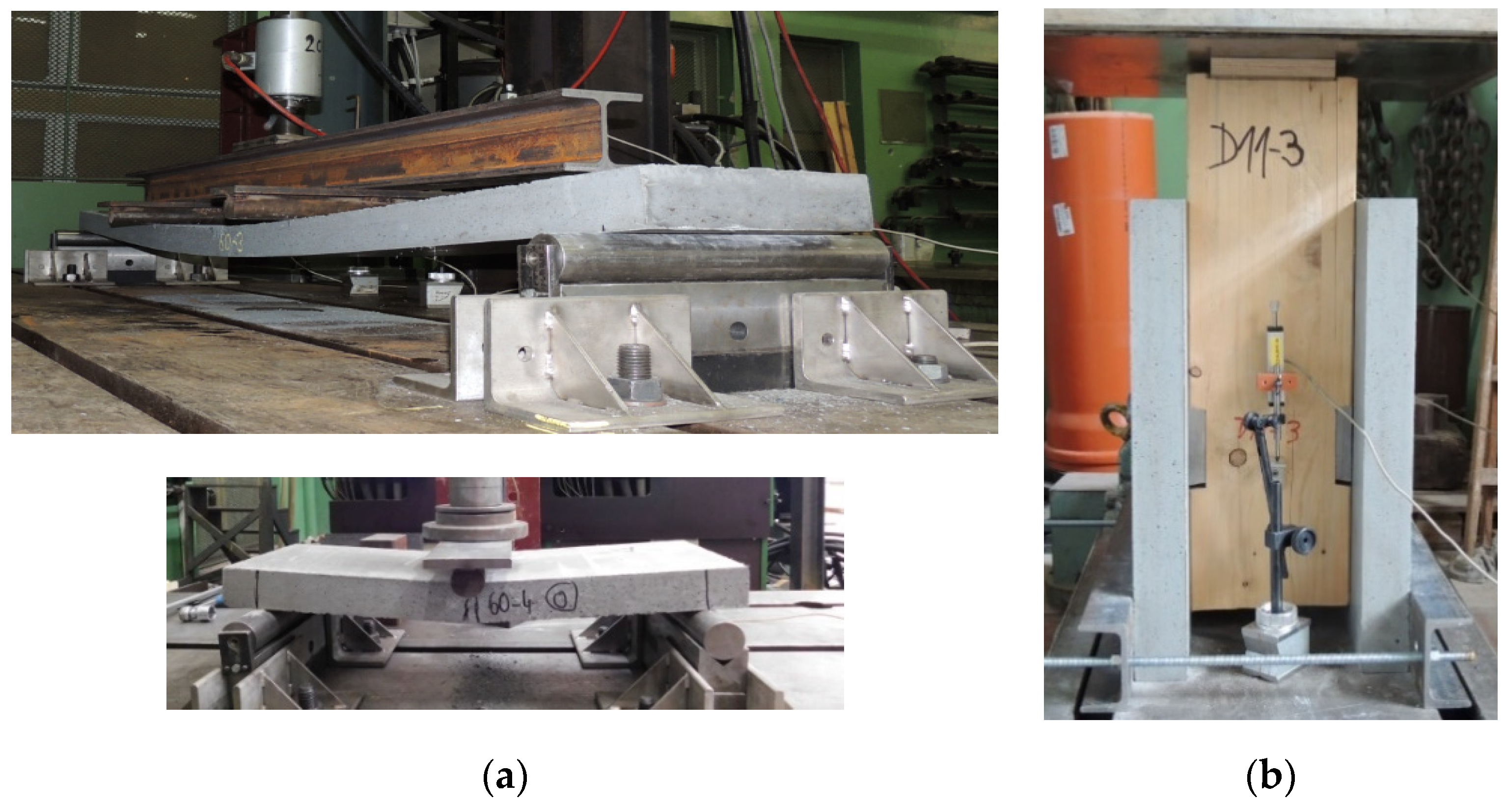
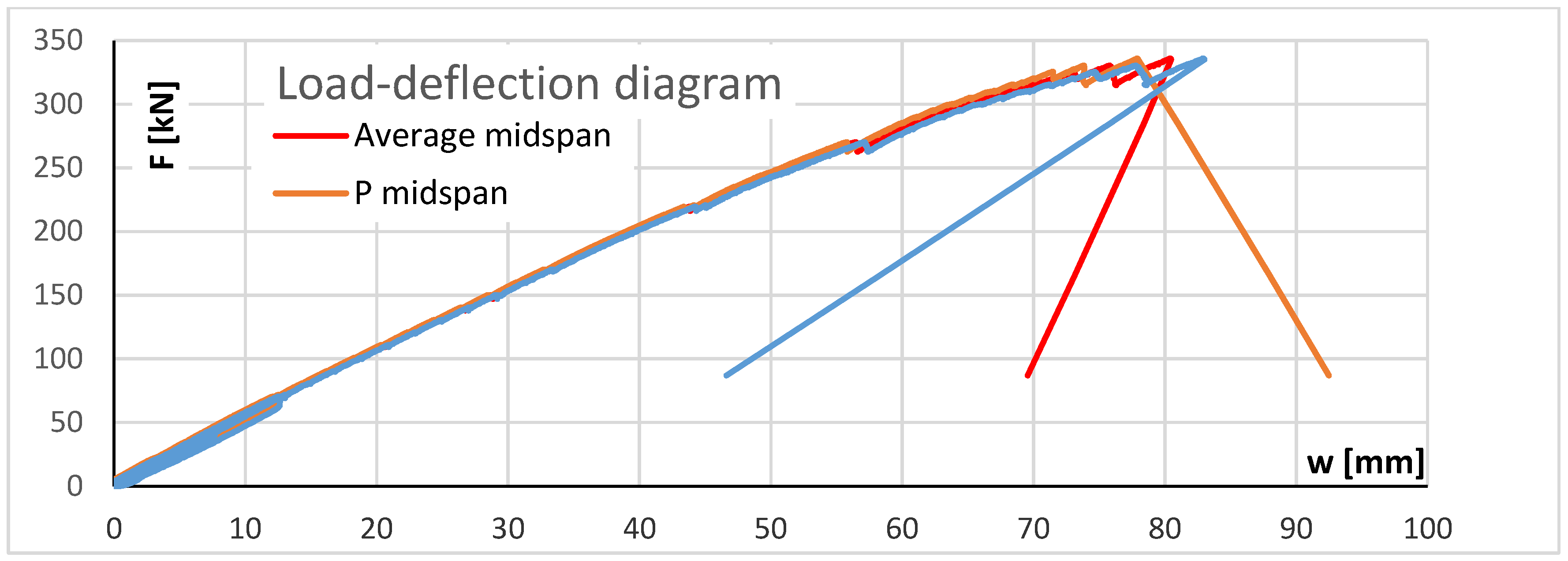
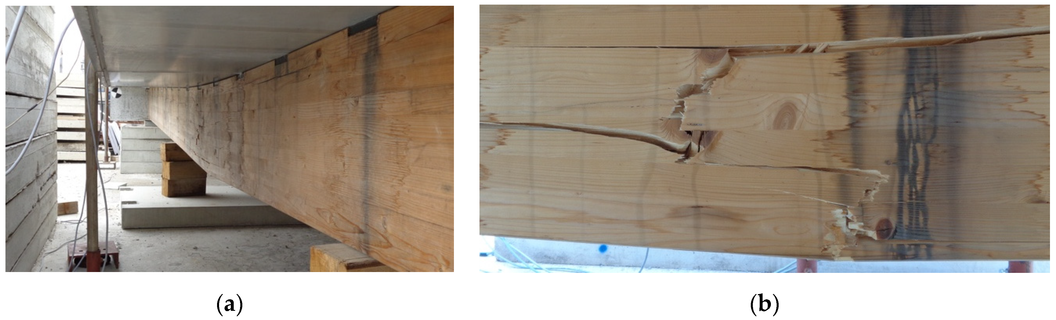
3.2. Load Test on Bridge Deck Segments

Although multiple bending tests were performed on special test specimens to design the optimal thickness of bridge deck segments (see [16,17]), a load test of the bridge deck in the transverse direction was also performed.
After the overall load test of the experimental bridge structure was performed, three test segments with a width of 1 m were cut from the intact part of the structure. The load test should confirm that the footbridge reacts elastically with a characteristic load combination (uniformly distributed pedestrian load of 5 kN/m2). The test segments were loaded gradually with sandbags (see Figure 11b).
The bridge deck in the transverse direction works as a simply supported beam with overhanging ends (see Figure 11a), which means that loading in the span also influences the deflection of the cantilevers and vice versa. During the test, the deflection and the load of the span and of both cantilevers were recorded as a function of time. Different load cases were tested, e.g., load on the cantilevers and load on the span, and sandbags were manually gradually repositioned from the cantilever to the span.
The loading procedure is evident from the diagrams in Figure 12, where the following values are recorded in time: uniformly distributed load acting on the span and on cantilevers and predicted deflection, measured and by calculation, in the span and on cantilevers. By the panels from 8.7. and 11.7., the cantilevers were first loaded and then the load was rearranged into the span. The measured deflections of the test segments from 8.7. and 11.7. were lower than the deflections estimated on the basis of linear elastic calculation. No damage, no cracks, and no plastic deformations were observed.
One of the cantilevers was tested for the maximum managed load with sandbags stacked on top of each other for every specimen. A maximum load of 1275 kg corresponding to a uniformly distributed load approx. 5 times higher than the characteristic pedestrian load (51 sandbags of 25 kg, sandbags tower height of approx. 1.9 m—see Figure 13a) was reached for the cantilever of panel from 10.7.2019. No visual failure was observed, and the measured deflection was slightly higher than the prediction from the elasticity calculation.
The way of loading was changed by the last test segment—panel from 10 July. The load was applied through a pair of timber blocks located in thirds of the span. The static schema of the loading test of the last test segment from 10 July was therefore arranged as a four-point bending test. Due to the limited number of sandbags (total 2270 kg), three pieces of reinforced concrete road panels weighing approximately 1000 kg each were used for loading in the first stage, and subsequently, sandbags were used (see Figure 13b).
Under the load of three road panels, a significant non-linear increase in deflection was observed (see Figure 13). During further application of sandbags, the development of cracks was observed and the cracking of steel fibers was recorded. Despite the application of all available sandbags and three road panels—a total load of 5.27 t—the load-bearing capacity of the test segment was not reached.

4. Discussion

4.1. Load Test on the Experimental Structure

The load test of the experimental bridge structure showed that the structure is safe and its behavior corresponds with the expectations. The actual load-bearing capacity of the structure was about five times higher than the design load. Based on known material characteristics, which were specified by additional material tests, a slip modulus k = 320 kN/mm was determined. The obtained value of slip the modulus corresponds to the slip modulus values determined from the push-out shear tests, which were performed before designing the experimental structure.
In the case of the timber–UHPC composite structures, the effects of non-force loads are greater than in the case of regular TCC structures. UHPC has an approximately 10% higher thermal length expansion coefficient and an approximately one-third higher modulus of elasticity compared to normal-strength concrete (C30/37). Because the bridge deck made of UHPC is slender and timber has lower thermal conductivity compared to concrete, a difference in temperature occurs between timber beams and the UHPC bridge deck while warming up and cooling down the structure. For the design of a composite bridge wood–UHPC structure, we considered the differential temperature component using the temperature difference between the two parts of the composite cross section, which is less favorable than considering the differential temperature component by a nonlinear method in the case of a normal concrete bridge deck.
In case of the UHPC application, the dead load of the structure is considerably lower than in the case of normal-strength concrete application, and this is the reason why the effects of the thermal load are, in relationship to dead and total loads, significantly higher. As for the connector design, the thermal load appears to be the determining component of load.

4.2. Load Test on Bridge Deck Segments

The load test of the bridge deck segments showed that the structure is safe and reacts elastically in the serviceability limit state. The measured deflections for the serviceability limit state corresponded well to the predicted deflections determined on the basis of linear elasticity calculation. The load-bearing capacity exceeds the design load by several times. Despite the application of all sandbags and three road panels—a total load of 5.27 t in the span (see Figure 14b)—a collapse of the structure was not reached.
The designed bridge system has its advantages and disadvantages as basically anything in the world. Composite bridge structures made of timber and concrete represent an environmental benefit because they allow the application of timber, a renewable natural material; effectively use the properties of both materials; and can be interesting from an architecture standpoint. The concrete bridge deck protects the timber beams against direct weather influences. The bridge deck made of UHPC is much slender compared to the bridge deck made of normal-strength concrete. Due to the use of UHPC, the dead load is significantly reduced and the effects of creep and shrinkage are reduced, especially in the case of prefabrication.
Manufacturing the TCC structure requires a collaboration of various different professions; therefore, it is more demanding for coordination of the work. Due to the fact that the beams are supposed to be delivered to the construction site already fitted with couplings elements, the designed system requires compliance to regularly strict manufacturing tolerances. It is therefore necessary to design relatively complicated details, which increases the manufacturing demands. When comparing qualities of individual parts of the structure, timber is definitely the weakest part of the whole system in terms of the load-bearing capacity and durability. In the case of a timber collapse, a brittle failure occurs. Although the timber beams are protected from direct effects of climatic conditions, their durability in the area of the contact joint between both materials will be probably lower than in the case of a UHPC bridge deck (durability of UHPC is estimated to be approximately 200 years). For this reason, it would be convenient to modify the connection system, so it would allow dismantling the bridge deck segments and their reuse.

5. Conclusions

This paper described the optimization of timber–concrete composite (TCC) bridge structures. This optimization consisted mainly of the application of a precast bridge deck made of ultra-high-performance concrete (UHPC or UHPFRC), which enables a reduction in the bridge deck thickness associated with a reduction in the dead load and provides other advantages: minimization of the wet process in contact with timber, faster construction progress, and reduction in shrinkage and creep effects.
TCC structures are a complex topic because these structures include various different complex materials and also because of their specific static behavior given by the semirigid connection. The research focused on prefabrication and, using UHPC for TCC structures, dealt with the computational analysis of TCC structures, with the design and analysis of specific types of coupling elements and with the design of a precast bridge deck made of UHPC in more detail. A number of experiments were carried out at the Klokner Institute of CTU in Prague under the support of the research project TH02020730 of the Technology Agency of the Czech Republic (TACR). The evaluation of the experiments was partially rendered within the elaboration of a PhD thesis [28].
The first part of the presented experiments was focused on the verification of mechanical characteristics of the proposed shear connection system. The shear connection is carried out by notches made of steel plates embedded in the timber beams supplemented with welded shear dowels (headed studs). The precast segments are provided with slots for the shear dowels, into which UHPC is poured after placing the deck segments on the timber beams.
Because UHPC is still a relatively new material in the Czech Republic and no standards have been issued yet, another part of our experiments was focused on the verification of the load-bearing capacity of thin slabs made of local mixture a of UHPC. Various bending tests for determining the flexural strength of UHPC were performed. Results of tests on special test specimens were compared with results of bending tests according to different valid standards.
The behavior of the optimized TCC bridge structure was explored both using parametric studies and experimentally. We created a computational program for the design and verification of TCC structures. The experimental full-scale bridge structure was built to verify some manufacturing details and the load-bearing capacity. After the overall load test was done, some bridge deck segments were cut from the structure and a load test of the bridge deck in the transverse direction was executed and the results were compared with analytical predictions.
The authors evaluate their work as an input impulse into the design of timber–UHPC composite bridge structures. The authors strongly believe that the achieved findings represent progress in the area of design of TCC bridge structures and in the area of design of UHPC structures.

Author Contributions

Conceptualization, M.H. and L.V.; methodology, M.H. and D.Č.; software, M.H.; validation, D.Č., P.T., and L.V.; formal analysis, M.H.; writing—original draft preparation, M.H. and D.Č.; writing—review and editing, M.H. and D.Č.; visualization, M.H.; supervision, L.V.; project administration, P.T. and L.V.; funding acquisition, P.T. and L.V. All authors have read and agreed to the published version of the manuscript.

Funding

This research was funded by the Technology Agency of the Czech Republic (TACR) (grant number TH02020730).

Institutional Review Board Statement

Not applicable.

Informed Consent Statement

Not applicable.

Acknowledgments

The research project was executed in cooperation with the company Valbek, Ltd. in Czech Republic. All experiments were performed by the staff of the Klokner Institute of CTU in Prague. The bridge deck segments and ballast road panels with supporting beams were produced by KS Prefa, Ltd. in Prague, Czech Republic.

Conflicts of Interest

The authors declare no conflict of interest.

References

  1. Ceccotti, A. Composite concrete-timber structures. Prog. Struct. Eng. Mater. 2002, 4, 264–275. [Google Scholar] [CrossRef]
  2. Yeoh, D.; Fragiacomo, M.; De Francheschi, M.; Koh, H.B. The state-of-the-art on timber-concrete composite structures—A literature review. J. Struct. Eng. 2011. [Google Scholar] [CrossRef]
  3. Rodrigues, J.; Dias, A.; Providencia, P. Timber-Concrete Composite Bridges: State-of-the-Art Review. BioResources 2013, 8, 6630–6649. [Google Scholar] [CrossRef] [Green Version]
  4. Simon, A. Brücken in Holz-Beton-Verbundbauweise—Renaissance Einer Genialen Idee: Vortrag, VSVI Mecklenburg Vorpommern; Seminar Brückenbau: Linstow, Germany, 2012. [Google Scholar]
  5. Kuklík, P.; Nechanický, P.; Kuklíková, A. Development of prefabricated timber-concrete composite floors. In Materials and Joints in Timber Structures; Aicher, S., Reinhardt, H.W., Garrecht, H., Eds.; RILEM Bookseries; Springer: Dordrecht, The Netherlands, 2014; Volume 9, ISBN 978-94-007-7811-5. [Google Scholar]
  6. Fragiacomo, M.; Lukaszewska, E. Development of Prefabricated Timber-Concrete Composite Floor Systems. Proc. Inst. Civ. Eng. Struct. Build. 2011, 164, 117–129. [Google Scholar] [CrossRef] [Green Version]
  7. Crocetti, R.; Sartori, T.; Tomasi, R.J. Innovative Timber-Concrete Composite Structures with Prefabricated FRC Slabs. Struct. Eng. 2015, 141, 04014224. [Google Scholar] [CrossRef]
  8. Set of Methodologies for Material Testing of UHPC and for Design Elements Made of UHPC, Output of Project TACR TA01010269; Klokner Institute CTU in Prague: Prague, Czech Republic, 2015.
  9. AFGC Ultra High Performance Fibre-Reinforced Concrete: Interim Recommendations; Revised Edition; AFGC Publication: Paris, France, 2013.
  10. Beton-Kalender. Teil 2, IX Ultrahochfester Beton UHPC; Ernst & Sohn: Berlin, Germany, 2013; pp. 117–240. [Google Scholar]
  11. Hájek, P.; Kynclová, M.; Fiala, C. Timber–UHPC composite floor structures—Environmental study. In Proceedings of the 3rd International Symposium on UHPC in Kassel in Germany, Kassel, Germany, 9–11 March 2012; ISBN 978-3-86219-265-6. [Google Scholar]
  12. Fragiacomo, M.; Gregori, A.; Xue, J.; Demartino, C.; Toso, M. Timber-concrete composite bridges: Three case studies. J. Traffic Transp. Eng. 2018, 5, 429–438. [Google Scholar] [CrossRef]
  13. Vítek, J.L.; Čítek, D. Joints of precast structures using UHPC. Solid State Phenom. 2017, 259, 164–169. [Google Scholar] [CrossRef]
  14. Vítek, J.L.; Čítek, D.; Coufal, R. UHPC Joints of Precast Elements. In Fibre Concrete 2013: Technology, Design, Application; CTU in Prague, Faculty of Civil Engineering: Prague, Czech Republic, 2013; pp. 407–414. [Google Scholar]
  15. Holý, M.; Vráblík, L. The Timber-Precast UHPC Composite Connection. Solid State Phenom. 2018, 272, 21–27. [Google Scholar] [CrossRef]
  16. Holý, M.; Tej, P.; Vráblík, L. Development of a timber-precast UHPFRC connection. In CONCRETE Innovations in Materials, Design and Structures, Proceedings of the Fib Symposium 2019, Kraków, Poland, 27–29 May 2019; Fédération Internationale du Béton: Lausanne, Switzerland, 2019; pp. 698–705. ISSN 2617-4820. ISBN 978-2-940643-00-4. [Google Scholar]
  17. Holý, M.; Vráblík, L. Push-out shear tests for timber-UHPC composite footbridge. In Proceedings of the 12th International Fib PhD Symposium in Civil Engineering, Fib Ph.D. Symposia, Prague, Czech Republic, 29–31 August 2018; Volume 12, pp. 195–202, ISBN 978-80-01-06401-6. [Google Scholar]
  18. Duque, L.F.M.; Varga, I.; Graybeal, B.A. Fibre reinforcement influence on the tensile response of UHPFRC. In Proceedings of the First International Interactive Symposium on UHPC—2016, Des Moines, IA, USA, 18–20 July 2016. [Google Scholar]
  19. Kolísko, J.; Rydval, M.; Huňka, P. UHPC—Assessment of steel fibre distribution and matrix homogeneity. In Fib Symposium TEL-AVIV 2013 Engineering a Concrete Future: Technology, Modeling & Construction—Proceedings; IACIE: Tel Aviv, Israel, 2013; pp. 113–116. [Google Scholar]
  20. Holý, M.; Čítek, D.; Tej, P.; Vráblík, L. Material properties of thin UHPC slabs used for timber-concrete composite bridge. In Proceedings of the 10th International Conference on Short and Medium Span Bridges (SMSB 2018), Quebec, QC, Canada, 30 July–3 August 2018. [Google Scholar]
  21. Holý, M.; Čítek, D.; Tej, P.; Vráblík, L. Flexural strength of thin slabs made of UHPFRC. In Proceedings of the 25th Concrete Days 2018; Solid State Phenomena; Trans Tech Publications: Curich, Switzerland, 2019; Volume 292, pp. 224–229. ISSN 1662-9779. ISBN 978-3-0357-1459-3. [Google Scholar]
  22. Kolísko, J.; Huňka, P.; Rydval, M.; Kostelecká, M. Development of UHPC from materials available in Czech Republic. In Proceedings of the CESB13, Prague, Czech Republic, 26–28 June 2013; pp. 385–388. [Google Scholar]
  23. Kolísko, J.; Čítek, D.; Tej, P.; Rydval, M. Production of Footbridge with Double Curvature Made of UHPC. In Proceedings of the IOP Conference Series-Materials Science and Engineering 246, Prague, Czech Republic, 13–16 September 2017. [Google Scholar] [CrossRef]
  24. Kněž, P.; Tej, P.; Čítek, D.; Kolísko, J. Design of Footbridge with Double Curvature Made of UHPC. In Proceedings of the IOP Conference Series-Materials Science and Engineering 246, Prague, Czech Republic, 13–16 September 2017. [Google Scholar] [CrossRef]
  25. ČSN EN 14080. Timber Structures—Glued Laminated Timber and Glued Solid Timber—Requirements (Czech Version of European Standard EN 14080:2013). 2013. Available online: https://csnonline.agentura-cas.cz/Detailnormy.aspx?k=94094 (accessed on 1 November 2013).
  26. ČSN EN 1990. Eurocode: Basis of Structural Design (Czech Version of European Standard EN 1990:2002). 2004. Available online: https://csnonline.agentura-cas.cz/Detailnormy.aspx?k=69473 (accessed on 1 April 2004).
  27. Rautenstrauch, K.; Grosse, M.; Lehmann, S.; Hartnack, R. Modellierung und baupraktische Bemessung von Holz-Verbund-Decken mit mineralischen Deckschichten unter Berücksichtigungneuartiger Verbindungsmittel. In Holz-Beton-Verbund; Bauwerk: Berlin, Germany, 2004; pp. 31–54. [Google Scholar]
  28. Holý, M. Optimization of Timber-UHPC Composite Bridges. Ph.D. Thesis, CTU, Prague, Czech Republic, 2020. [Google Scholar]
Figure 1. Experiments performed at the Klokner Institute. (a) Special slab specimens—at the top, the 4-point bending test with a 1.9 m span; at the bottom, the 3-point bending test with a 0.6 m span. (b) Timber–UHPC composite test specimen during the push-out shear test of connectors.
Sustainability 13 04895 g001
Figure 2. (a) Cross section of the experimental timber–UHPC composite structure (dimensions in millimeters). (b) Test placement of bridge deck segments made of UHPC on timber beams (before installing connectors).
Sustainability 13 04895 g002
Figure 3. Assembly drawing of bridge deck segments (dimensions in millimeters).
Sustainability 13 04895 g003
Figure 4. Detail of placement of panels on the coupling elements (dimensions in millimeters).
Sustainability 13 04895 g004
Figure 5. Setup of the load test (dimensions in millimeters).
Sustainability 13 04895 g005
Figure 6. The computational model of the structure in the SCIA Engineer program.
Sustainability 13 04895 g006
Figure 7. Record from the load test—load on the hydraulic cylinder and deflection in the middle of the span, depending on time.
Sustainability 13 04895 g007
Figure 8. Record from the load test—load on the hydraulic cylinder and slip between beams and the bridge deck on the ends of timber beams, depending on time (LP = failed beam left end; PP = failed beam right end; LZ = remaining beam left end; PP = remaining beam right end).
Sustainability 13 04895 g008
Figure 9. Record from the load test—load–deflection diagram (P = failed beam; Z = intact beam).
Sustainability 13 04895 g009
Figure 10. (a) View of the tested structure after tensile failure of the timber beam in the middle of the span. (b) Detail of the tensile failure at the bottom of the timber beam.
Sustainability 13 04895 g010
Figure 11. (a) Cross section of the test specimen with marked load areas—cantilever K1, span P, and cantilever K2 with uniformly distributed loads f K1, f K2, and f P and with marked points for measuring of deflection w K1, w K2, and w P. Below in the picture: static schema for prediction of deflection. (b) Simulation of the characteristic value of the uniformly distributed pedestrian load—5 kN/m2 using sandbags placed on the cantilevers and in the span.
Sustainability 13 04895 g011
Figure 12. Records of the load test of individual test segments: w = deflection (positive = sagging; negative = hogging)—meas. = measured and pred. = predicted by calculation; f = uniformly distributed load; P = span; K1, K2 = cantilevers.
Sustainability 13 04895 g012aSustainability 13 04895 g012b
Figure 13. (a) Sandbags placed on the cantilever with total weight ca. 1275 kg (corresponding to ca. 25.5 kN/m2). (b) Loading in the span using reinforced concrete road panels and sandbags with total weight ca. 5270 kg (corresponding to ca. 33 kN/m2).
Sustainability 13 04895 g013
Figure 14. Record of the load test of the test segment from 10 July 2019 for estimation of load-bearing capacity: w = deflection (positive = sagging and negative = hogging)—meas. = measured and pred. = predicted by calculation; f = uniformly distributed load; P = span; K1, K2 = cantilevers. The segment was gradually loaded first with 3 road panels and then with sandbags. The point sensors on the cantilevers were out of range by a deflection of about −15 mm.
Sustainability 13 04895 g014
Table 1. Material properties of UHPC at the age of 28 days.
Material PropertyMean ValueNumber of SpecimensCoefficient of VariationStandard
Deviation
Density2450kg/m3480.84%20.6
Compressive strength (cubes a = 100 mm)144.2MPa3611.4%16.4
Compressive strength (cylinder Ø150 mm)131.0MPa1510.6%13.9
Modulus of elasticity49.6GPa153.70%1.8
Table 2. Mean values of density of used glulam timber of class Gl24h, comparison of density according to standards [25], and density from material tests corresponding to wood moisture of 12%.
Timber GradeDensity According to Standards [25]Density Determined Experimentally
ρmean (kg/m3)ρmean,real (kg/m3)
GL24h420422
Table 3. Basic material properties of glulam timber of class Gl24h according to ČSN EN 14 080 [25].
Characteristic value of bending strength, fm,k24.0MPa
Characteristic value of tension strength parallel to grain, ft,0,k19.2MPa
Characteristic value of shear strength, fv,k3.5MPa
Mean value of modulus of elasticity parallel to grain, E0,g,mean11.5GPa
Table 4. Calculated design internal forces and deflection in midspan for the final structure—fd design uniformly distributed load (dead load + live load), M bending moment, V shear force, and w deflection. Material characteristics considered as in SLS, at time 0 (temperature load neglected).
Load Comb.fdMVW
(kN/m)(kNm)(kN)(mm)
6.1031.0435014718.5
Characteristic22.9925910913.7
Frequent13.99158668.3
Table 5. Simulation of design internal forces using 4-point bending and comparison of predicted deflections with measured deflections—g dead load of the structure, G dead load of hydraulic cylinders with steel transfer beam, F force on the hydraulic cylinder, wnet,calc calculated deflection caused by F, and wnet,meas measured average deflection.
Load Comb.gGFMVwwnet,calcwnet,meas
(kN/m)(kN)(kN)(kNm)(kN)(mm)(mm)(mm)
M—6.106.16367.13509917.313.012.4
M—char.6.16344.52597712.98.67.5
V—frequent6.163342176610.86.66.2
Publisher’s Note: MDPI stays neutral with regard to jurisdictional claims in published maps and institutional affiliations.

