Abstract
The article focuses on the description of an innovative solution and application of active thermal protection of buildings using thermal insulation panels with active regulation of heat transfer in the form of a contact insulation system. The thermal insulation panels are part of a prefabricated lightweight outer shell, which together with the low-temperature heating and high-temperature cooling system creates an indoor environment. The energy source is usually renewable energy sources or technological waste heat. Research and development of an innovative facade system with active thermal protection is in the phase of computer simulations and preparation of laboratory measurements of thermal insulation panels with various combinations of energy functions. In the article we present theoretical assumptions, calculation procedure and parametric study of three basic design solutions of combined energy wall systems in the function of low-temperature radiant heating and high-temperature radiant cooling.
1. Introduction
The active thermal protection (ATP) system, based on the active control of heat transfer by changing the temperature at the interface of the supporting and thermal insulation parts of a building envelope, can fulfil the function of several “energy systems”. Combined building energy systems with active thermal protection (ATP) represent the optimal and most comprehensive technical solution for buildings within the meaning of Directive 2018/844/EU, which amends Directive 2010/31/EU on the energy performance of buildings and Directive 2012/27/EU on energy efficiency, which introduced a new concept into our legal system—“almost zero energy building (nZEB)” [1].
The aim of this technology is all categories of buildings (residential buildings, civic amenities, industrial halls, buildings in agriculture), whose perimeter cladding is made of non-transparent materials such as reinforced concrete panels, reinforced concrete monolithic walls, walls of bricks and blocks, or metal-based and wood.
If the renovated buildings have been only heated, the present invention solves energy savings not only by thermal insulation that actively allows to control the heat transfer through the building envelope but also the multifunctional of the thermal insulation system, with an integrated energy system from the exterior tents of the building of the building for RES (renewable energy sources)—solar energy and energy. The surrounding environment in conjunction with heat pumps, from the interior in the function of thermal barrier, low-temperature heating, high-temperature cooling, heat accumulation and heat recovery. This multifunctional system can also use waste heat from various technologies.
The aim of the article is to describe the technology of production of thermal insulation panels with various energy functions, instructions for implementation of innovative thermal insulation facade with ATP on the building, presentation of theoretical assumptions, calculation procedure and parametric study of three basic design solutions of combined energy wall systems in low temperature radiant heating and radiant cooling.
The innovative facade solution with active thermal protection follows the research of combined energy systems of buildings, especially low-temperature radiant heating, high-temperature radiant cooling, thermal barrier and TABS (thermal active building structures), which is described mainly in several scientific studies [2,3,4,5,6,7,8,9,10,11,12].
2. Current State of Technical Solutions
In terms of the thermal protection of buildings, structures with an internal energy source form progressive packaging structures of buildings with active control of the heat transfer (thermal barrier). From an energy point of view, they are multifunctional with one or combined functions of low-temperature radiant heating/high-temperature cooling, heat/cold storage, heat recovery, collectors for solar energy or ambient energy in combination with heat pumps. New, investigated variants of building structures with an internal energy source using exhaust air can also have the function of recuperative heat exchangers in forced ventilation of buildings. From an environmental point of view, building and energy systems with ATP have optimal use in the use of RES (renewable energy sources) and waste heat. When preparing the production of electricity, for example photovoltaic power plants, buildings can be combined building-energy systems with ATP a suitable alternative for self-sufficient or to plus buildings.
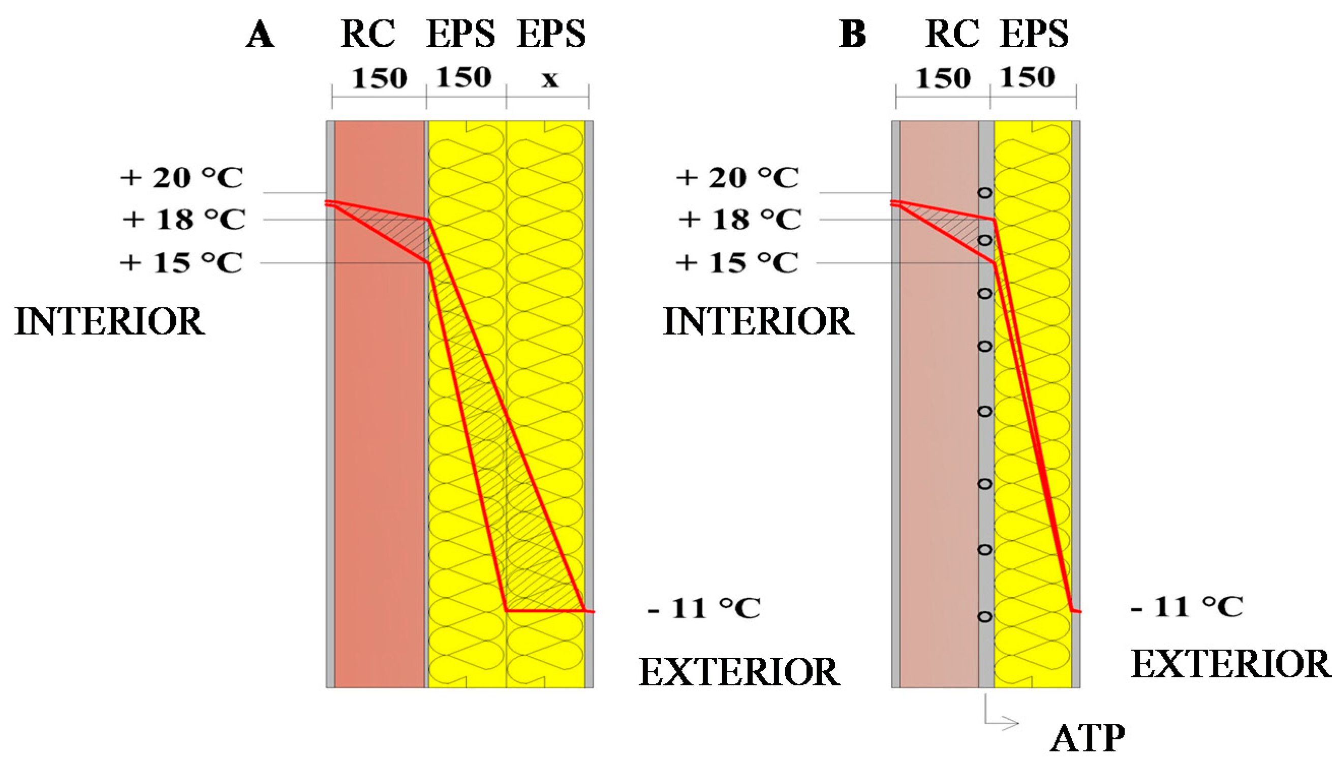
ATP are pipe systems embedded in envelope building structures, shown in Figure 1B, to which a heat-transfer medium (heating or cooling water or air) at regulated temperature is supplied. These are building structures with an internal energy source and they form a combined building and energy system. From the point of view of thermal protection of buildings, it is important that thermally insulated building structures have the highest possible surface temperature between the layers of the load-bearing and the thermal insulation part. This can be achieved with greater thickness of thermal insulation, shown in Figure 1A, or the temperature of the heat-transfer medium in the ATP pipe systems in the building structure, see Figure 1B.
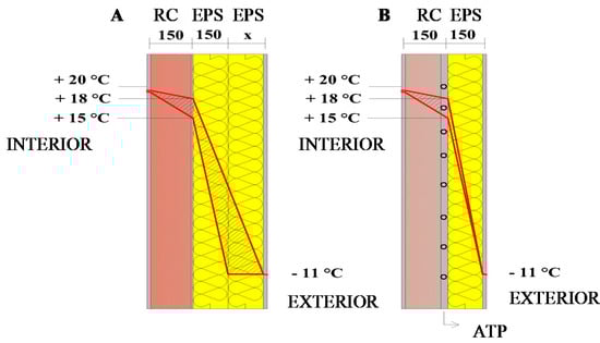
Figure 1.
Surface temperature between layers of the load-bearing and thermal insulation part of building structures with classic contact thermal insulation system (A) and a system with ATP (B). RC—reinforced concrete, EPS—expanded polystyrene, x—increased thickness of thermal insulation, ATP—active thermal protection (author: Kalús) [3,13,14].
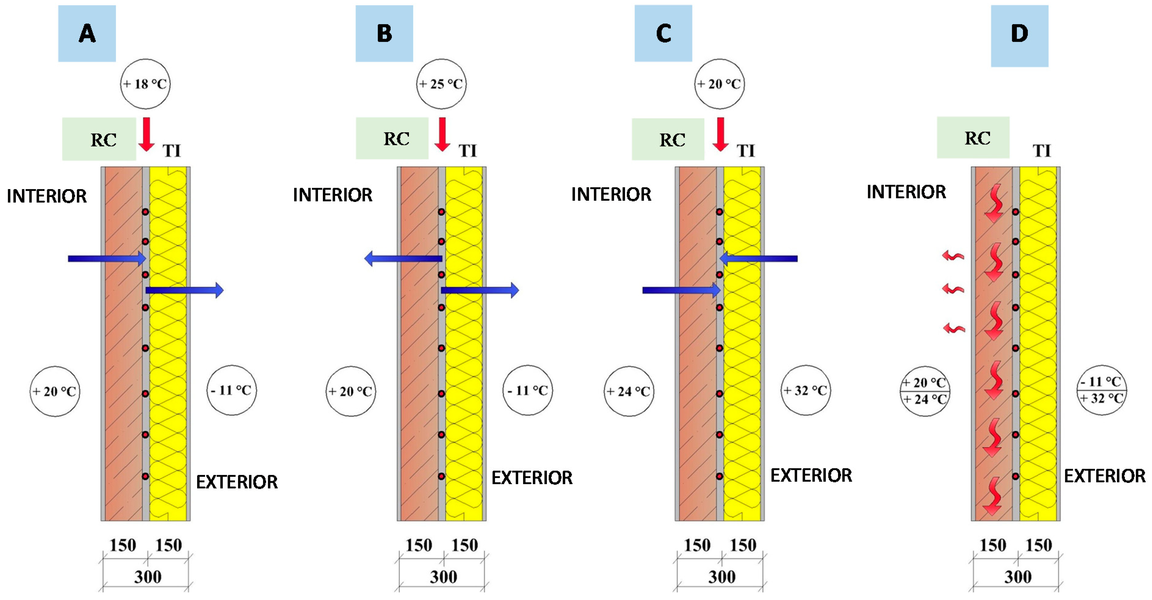
The active thermal protection (ATP) system based on the active control of heat transfer, by changing the temperature at the interface of supporting and thermal insulation parts of the building envelope, shown in Figure 2, can fulfil the function of several “energy systems”. For instance, it can have a function of thermal barrier, low-temperature heating, high-temperature cooling and heat/cold accumulation in the load-bearing part of building structures. Under certain conditions, ATP can serve as a heat recuperator or as an energy collector for an application with a heat pump. An ATP is made of pipe systems (usually plastic circuits) embedded in building structures, through which a working medium circulates heated by any heat source (CHP—central heat power, natural gas or biomass boilers, heat pumps...). The main function of the system is to decrease or eliminate heat losses through non-transparent structures in winter and at the same time to decrease or eliminate heat gains in summer. It is in particular recommended to apply renewable energy sources with respect to low required temperatures of the heating medium, and thereby to shorten the heating period of the building. Application of ATP in combination with waste heat is recommended as well. Buildings where this system is applied have low energy consumption and therefore meet the requirements of Directive no. 2018/844/EU, according to which, from 01.01.2021, all new buildings for housing and civic amenities should have energy demand close to zero [1].
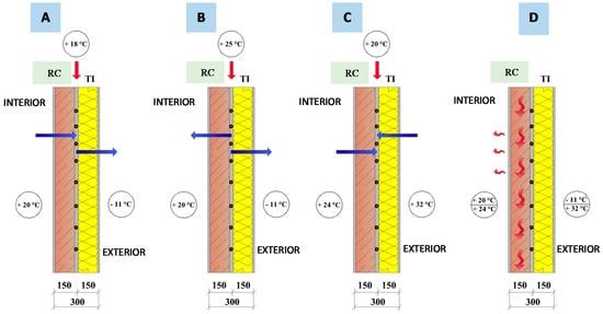
Figure 2.
The multiple-function character of ATP (water based) (author: Kalús) [3,13,14]. RC—reinforced concrete; TI—thermal insulation; (A)—thermal barrier; (B)—heating; (C)—cooling; (D)—heat/cold accumulation.
Active thermal protection (ATP) wall energy systems with one or two thermal barriers, as described, are already known, e.g., in patent SK 284 751 [15]. This is a wall energy system ISOMAX originating from Luxembourg (author: Krecké Edmond D.; Beaufort; LU—considered to be the originator of the idea of active thermal protection in the form of a thermal barrier), which, similar to the TABS systems (thermal active building structures), uses thermal active material. In the sense of the technical solution presented in the patent SK 284 751 [15], ATP is applied in two ways. During its operation, this system uses heat obtained from solar radiation, which is stored in heat storages, to actively reduce heat loss through enveloping structures. During the heating season, water is supplied to the pipes from the ground heat storage tank; the average temperature of the heating water is in the range of 15 to 20 °C. Cold water from the ground pipe register is used for cooling in the summer. Unlike TABS, this system does not only use a concrete core, shown in Figure 3, but it can also use wall storage core made of any material with high heat storage properties, shown in Figure 4, or both methods can be applied, shown in Figure 5 [5,10,11,15].
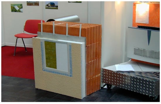
Figure 3.
Application of the ISOMAX system in the sense of patent SK 284 751 on the exterior surface of perimeter walls of a building [15,16,17,18].
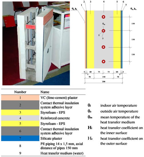
Figure 4.
Single-pipe wall energy system ISOMAX in the sense of patent SK 284 751 [15,16,17,18,19].
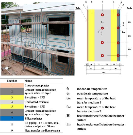
Figure 5.
Two-pipe wall energy system ISOMAX in the sense of patent SK 284 751 [15,16,17,18,19].
3. Basic Calculation for Dimensioning
Research and development of an innovative facade system with active thermal protection is in the phase of preparation of computer simulations and preparation of laboratory measurements of thermal insulation panels with various combinations of energy functions. In this part we present theoretical assumptions, calculation procedure and parametric study of 3 basic design solutions of combined energy wall systems in the function of low-temperature radiant heating and high-temperature radiant cooling.
Before designing the system, it is necessary to determine the temperature in the layer in which the ATP will be located. The calculation must be performed under various external and internal conditions. For correct function of the system, it is necessary to know the change in temperature in this layer under influence of changes in external conditions. It is advisable to create a dependence curve. Not knowing the conditions can lead to unnecessary waste of energy, or even discharging of the heat storage. An example was performed on perimeter structures. The assessment was processed for indoor air temperature 20 °C (heating season) and 26 °C (summer season) and outdoor air temperature −18 °C, −11 °C and 0 °C. In summer, outdoor air temperature of +32 °C was considered. As an example, three structures will be examined:
- Structure A—consists of a reinforced concrete load bearing structure 200 mm thick (reinforced concrete), which is insulated from the outside with polystyrene 120 mm thick. The ATP would be placed in a layer of mortar bed between the load-bearing wall and the insulation, shown in Figure 6;
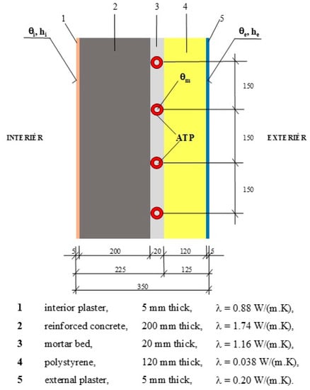 Figure 6. Perimeter wall construction with ATP—structure A [20,21].
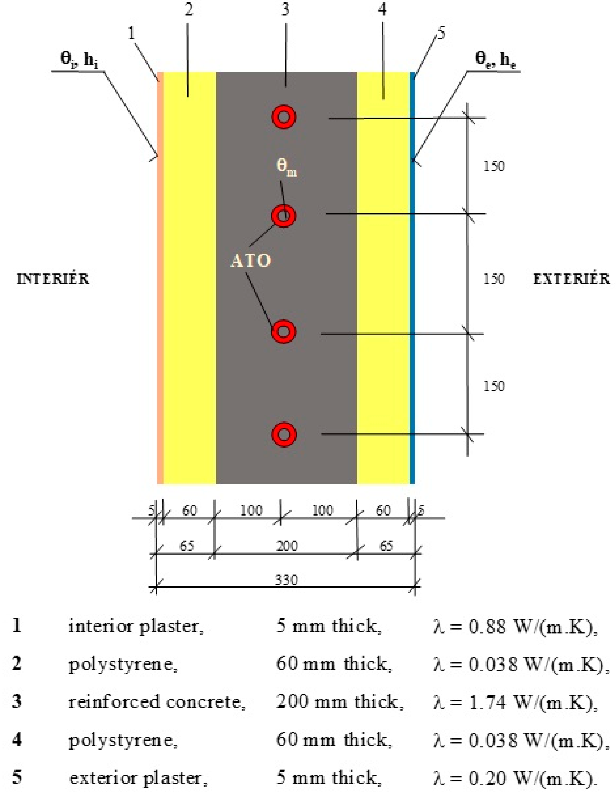
 - Structure B—consists of a reinforced concrete load bearing structure 200 mm thick, which is insulated on the exterior and interior side with polystyrene 60 mm thick. The ATP would be located in the middle of the load bearing structure, shown in Figure 7;
 Figure 7. Perimeter wall construction with ATP—structure B [20,21].
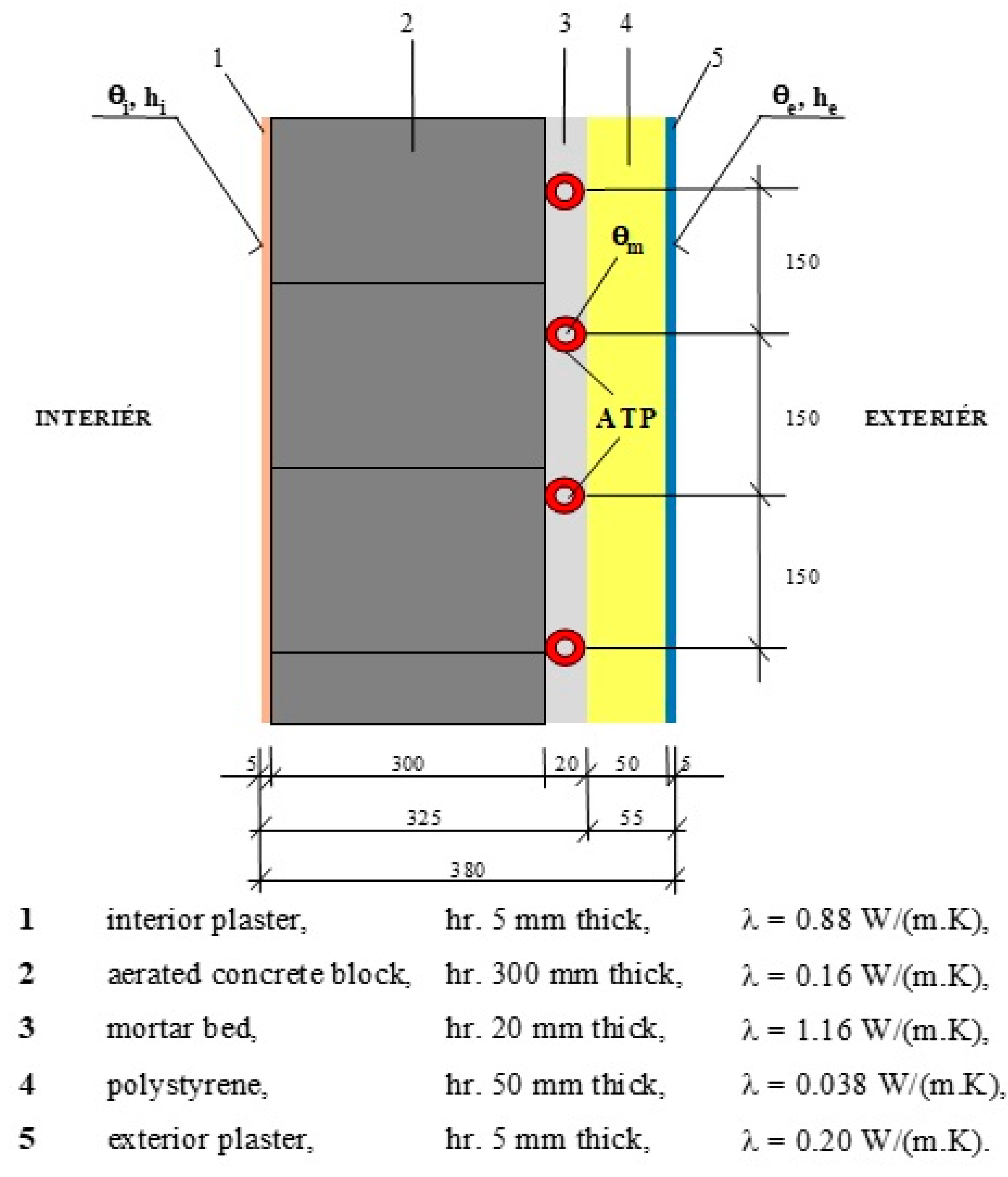
 - Structure C—consists of aerated concrete blocks (PBT) 300 mm thick and insulated from the exterior with polystyrene 50 mm thick. The ATP would be placed in between, shown in Figure 8.
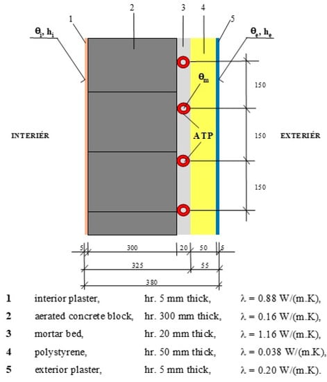 Figure 8. Perimeter wall construction with ATP—structure C [20,21].
Structures with the same heat transfer coefficient have diametrically different temperatures at the ATP location. For structure A, it ranges from 16 °C (at θe = −18 °C) to 17.9 °C (at θe = 0 °C). The temperature in the ATP pipe as a thermal barrier must therefore be higher. For structure B, the ATP would be located in the middle of the reinforced concrete structure, where the temperature ranges from 0 °C (at θe = −18 °C) to 9.5 °C (at θe = 0 °C). For structure C, the temperature ranges from −3.0 °C (at θe = −18 °C) to 7.9 °C (at θe = 0 °C). A building structure that would have inverted layers such as structure A, i.e., thermal insulation from the interior and reinforced concrete from the exterior, has not been assessed. Such a structure would have the highest heat fluxes to the exterior and the temperature in the ATP layer would be below 0 °C. The circulating medium should not be water. The task will be to further calculate the heat flux from the interior and the heat flux from the ATP to the exterior, so that the system can be evaluated in more detail.
Heat exchange in the ATP system represents combined heat transfer by convection and radiation. Heat transfer occurs on the inside and outside of the building structure. On the inside of the building structure there is:
- Air flow, as the air is warmer in the higher positions and colder in the lower positions;
- Radiation as a consequence of the heat exchange of a given structure with all other room structures.
On the outside of the building structure there is:
- Air flow mostly along the structure due to wind;
- Radiation between a given surface of a structure and the sky, between surrounding buildings and terrain [12,22,23,24].
The following relations will be used to calculate the heat flow from the ATO [12,22,23,24]: Average temperature of the structure in the axis of the pipes:
θd—is the average temperature of the structure in the axis of the pipes (°C),
θi—calculated internal room temperature (°C),
θm—average heating water temperature (°C),
L—axial distance of pipes (m),
m—coefficient characterizing the heating plate in terms of heat dissipation (m−1).
Coefficient characterizing the heating plate in terms of heat dissipation:
Λa—thermal permeability of the layer in front of the pipes toward the interior (W/(m2.K)),
Λb—thermal permeability of the layer behind the pipes toward the exterior (W/(m2.K)),
λd—thermal conductivity of the material into which the tubes are inserted (W/(m.K)),
d—pipe diameter (m).
Thermal permeability of the layer in front of the pipes toward the interior:
Thermal permeability of the layer behind the pipes toward the exterior:
a—thickness of the layer in front of the pipes (m),
b—thickness of the layer behind the pipes (m),
λa, λb—thermal conductivity of the material of the respective layer (W/(m.K)),
αp—heat transfer coefficient toward the interior (W/(m2.K)),
α’p—heat transfer coefficient toward exterior (W/(m2.K)).
Average surface temperature of the structure:
Specific heat output (flow) from the structure toward the interior:
Specific heat output (flow) from the structure toward the exterior:
The following values were calculated for structures A, B and C: θd—average temperature of the structure in the axis of pipes (°C), θp—average surface temperature of the structure in the interior (°C), q—heat flow from the structure toward the interior (W/m2) and q″—heat flow from the structure toward the exterior (W/m2). The calculation was performed for the winter (ATP as a wall heating and thermal barrier) and the summer (ATP as a wall cooling function). Boundary conditions: external dimension of the ATP pipe = 16 mm, spacing between the pipes = 0.20 m, heat transfer coefficient toward the interior = 8 W/(m2.K) (in accordance with STN EN 15377-1 and ČSN 730548), heat transfer coefficient toward the exterior = 15 W/(m2.K) (in accordance with ČSN 730548). In simplified calculation relations, the same air temperature in front of and behind the pipes was considered when calculating the average structure temperature in the pipe axis and the average surface temperature in accordance with [12,24]. The results of the calculations for winter are shown in Table 1. Outside air temperature θe = −11°C was considered, internal air temperature θi = 20 °C and mean working medium temperature in the ATO pipeline θm = 20 to 45 °C. The calculation was processed in Excel.

Table 1.
Average temperature in the pipe axis θd (°C), average surface temperature θp (°C), heat flux toward the interior q (W/m2) and heat flux toward the exterior q″ (W/m2) for structures A, B and C (wall heating, thermal barrier) [20,21].
Comparison of structures brings the following results:
- Building structure A consists of the interior in front of the ATP made of a material with high thermal conductivity and low thermal resistance (reinforced concrete) and behind the ATP towards the exterior made of a material with low thermal conductivity and high thermal resistance (polystyrene). As a result, a higher surface temperature in the interior, a higher heat flux toward the interior and a lower heat flux toward the exterior are achieved compared to structures B and C. Surface temperature θp e.g., at mean temperature of the working medium θm = 35 °C in the ATP pipe starts at 26.61 °C, while at structure B = 21.03 °C and structure C = 20.90 °C. The heat flux toward the interior at θm = 35 °C is 52.896 W/m2. Compared to structure B (8260 W/m2), this value is more than 6 times higher and compared to structure C (7166 W/m2) more than 7 times higher. The heat flux toward the exterior is by almost half lower than with structure B. The difference is even greater compared to structure C;
- Building structures B and C consist of materials with low thermal conductivity and high thermal resistance in front of and behind the ATP. The heat flow toward the interior is considerably limited, compared to structure A the values are significantly lower. A higher average temperature in the pipe axis (θd) is generated in the layer where the ATP is located. However, as the temperature in the ATP pipe increases, the surface temperature in the interior increases only minimally. For example, in structure C, at the mean temperature of the working medium θm = 25 °C the surface temperature is θp = 20.30 °C, at θm = 45 °C θp = 21.49 °C. The heat flux toward the exterior is higher.
The ATP was further assessed in a wall cooling function. The results are shown in Table 2. Outside air temperature θe = 32 °C, indoor air temperature θi = 26 °C and mean working fluid temperature θm = 16 °C to 21 °C were considered.
Table 2.
Average temperature in the pipe axis θd (°C), average surface temperature θp (°C), heat flow toward the interior q (W/m2) and heat flow toward the exterior q″ (W/m2) for structures A, B and C (wall cooling) [20,21].
Heat fluxes are negative, because the temperature of the working medium in the pipe is lower than the air temperature in the exterior and interior. It is clear that the wall cooling is of the greatest importance in structure A, i.e., in the structure which has high thermal conductivity and low thermal resistance from the pipes toward the interior. Due to the fact that behind the ATP towards the exterior there is a material with high thermal resistance, the heat flux toward the exterior is significantly lower. The surface temperature in the interior of structure A decreases significantly from 23.80 °C (at θm = 21 °C) to 21.59 °C (at θm = 16 °C).
In structures B and C, the heat flow (cold) toward the interior is considerably limited and, conversely, the heat flow (cold) to the exterior is significantly higher. This means that the temperature in the return pipe will be higher. The surface temperature in the interior changes only minimally—e.g., for structure B from 25.66 °C (at θm = 21 °C) to 25.31 °C (at θm = 16 °C). Wall cooling in building structures that have low thermal conductivity and high thermal resistance towards the interior in front of the ATP is considerably limited. In principle, it is only possible to cover heat gains through non-transparent structures.
4. Research and Development of Facade Systems with Active Thermal Protection
4.1. Focus of Research
The ISOMAX system described in the patent document SK 284 751 seems to be a very promising idea for the construction of buildings with nearly zero energy using renewable energy sources, but on the other hand it has an unresolved mode of operation and complicated, technologically lengthy implementation of pipe systems in the application on walls of new, or renovated buildings, from which the following shortcomings result. The aim of research in the field of combined building-energy systems is to solve the defined shortcomings so that:
- (a)
- Heat/cold sources for energy systems—heating, hot water preparation, ventilation, and cooling—were stable, independent of variable and unpredictable solar and geothermic energy accumulated in large-capacity, especially in ground heat storage;
- (b)
- The requirements for buildings with nearly zero energy demand have been met;
- (c)
- RES are used as much as possible and the best possible accumulation of heat/cold from these sources is ensured;
- (d)
- The implementation of active thermal protection has been simplified;
- (e)
- The advantages of contact thermal insulation system have been economically effectively combined with energy systems—thermal barrier, heating, cooling, heat accumulation and recuperation, capture of solar and ambient energy and use of recuperative ventilation—in multifunctional building-energy constructions of buildings;
- (f)
- A compact heat station with a separate control system was designed to regulate, measure, and optimize the energy demand in the building;
- (g)
- A reliable exact calculation methodology was developed for the design, calculation, selection, and assessment of all components of the combined building and energy systems of a building.
The solution of these research goals is in the phase of computer simulations of mathematical-physical models of combined energy wall systems in terms of utility model: “Self-supporting thermal insulation panel for systems with active heat transfer control” [25], as well as laboratory measurements of physical models of intelligent compact devices using RES according to the utility model: “Method of operation of a combined construction-energy system of buildings and equipment” [26] on an optimizer and simulator of compact devices.
Next, we describe an innovative solution and simplification of the application of active thermal protection, research and development of thermal heat insulating panels with active regulation of heat transition and multifunctional use of these panels in practice in accordance with the European patent: “Heat insulating panel with active regulation of heat transition” [13], implemented research projects [20,27,28,29,30] and defended dissertations [19,21,31].
4.2. Description of Innovation
Classic contact facade thermal insulation systems—thermal insulation panels, for example, based on polystyrene plates or mineral wool boards without active heat transfer control (active thermal protection)—are characterized by the fact that their thermal resistance depends directly on the thickness of the thermal insulation. Their function is only to create the packaging structure of the building. They cannot actively respond to the immediate changes in outdoor temperature. They do not have the function of providing heating, cooling and ventilation of the building.
The shortcomings mentioned above of existing systems of heat insulating panels constructions without active heat regulation—with respect to their limited function, higher operating costs of the building and the saving of primary sources of energy—lead to the possibility to solve this problem by appropriate technological means.
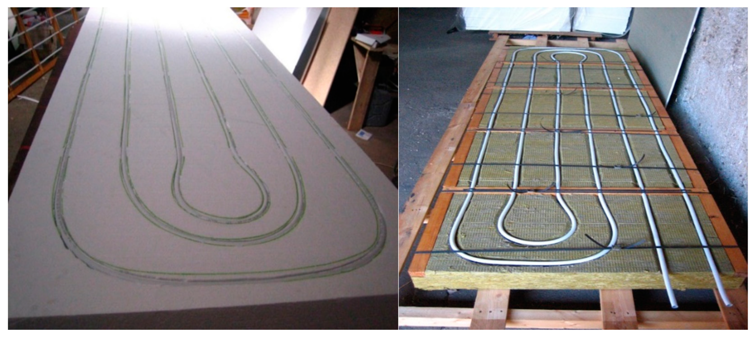
The result of this effort are variants of the construction of thermal insulation panels with active regulation of heat transfer (active thermal protection—ATO) according to the invention described in the European patent specification EP 2 572 057 B1, [13]. These are built-in pipe systems in the building constructions, to which a heat transfer medium (water, air) with a modified temperature (it is thus a matter of creating a combined building-energy system) is supplied. Figure 9 (on the left) presents a photo of a prototype thermal insulation panel with active heat transfer control/milled grooves in expanded polystyrene foam, and Figure 9 (on the right) shows an alternative of a prototype mineral wool panel.
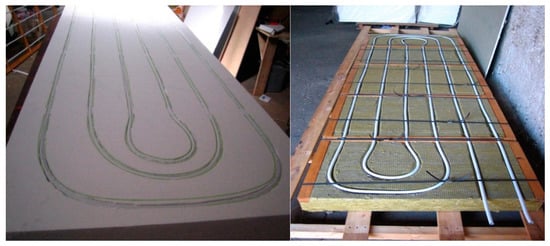
Figure 9.
Prototype of a panel with ATP, expanded polystyrene, dimensions 2000 × 1000 × 100 mm (heat transfer medium—water) (on the left), Prototype of thermal insulation panel ATP—supporting frame—mineral wool, dimensions 2000 × 1000 × 100 mm (heat transfer medium—water) (on the right) (author: Kalús) [3,13,14].
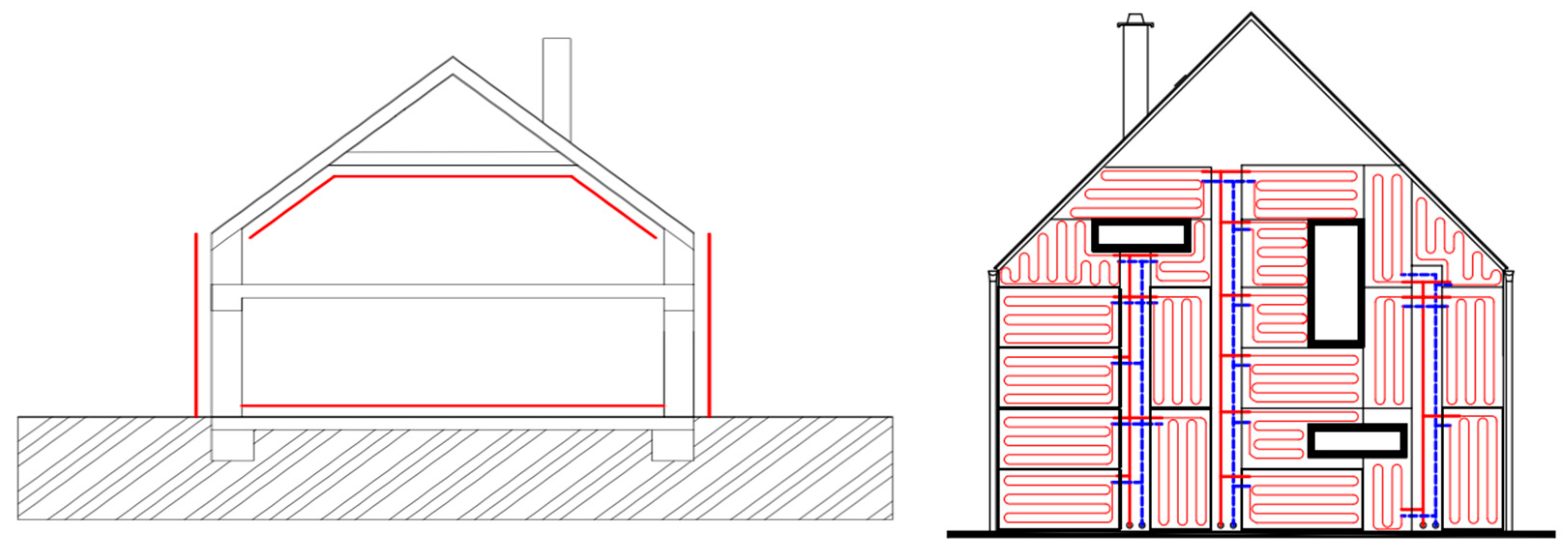
ATP is applied on all non-transparent structures—floor, walls, and roof, shown in Figure 10 (on the left). So far, ATP was realized by mechanical anchoring of distribution pipes on a wall, multiple rendering of the pipes and subsequent gluing on thermal insulation with finishing of the facade [3,13,14]. Thermal insulation panels (TIP) with integrated active thermal protection in the form of pipes or canals represent an intelligent contact insulation system made by a standard procedure from the same materials and by the same technological procedure as a classic contact thermal insulation system [13,14].
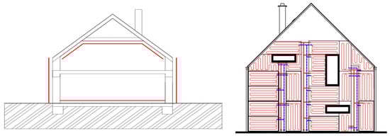
Figure 10.
Principle of application of ATP on a building—ATP forms an active “envelope” of the building (on the left). Connection of panels with ATP (water as the heat-transfer medium) to the supply and return heating/cooling distribution pipes (on the right) (author: Kalús) [3,13,14].
The principle of contact thermal insulation systems with ATP is shown in Figure 10 (on the right), which depicts one of the possible variants of composition of thermal insulation panels with ATP.
4.3. Technology of Production of Thermal Insulation Panels with Active Regulation of Heat Transfer
A contact thermal insulation system with ATP is formed by panels with standard dimensions (2000/1850/1600/1550 × 1000 × thickness minimum 100 mm) and non-standard panels tailor-made according to the laying plan, shown in Figure 11.
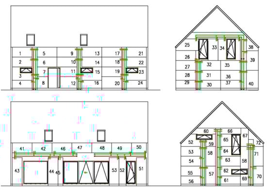
Figure 11.
Principle of construction of a contact thermal insulation system using thermal insulation panels with ATP (water as the heat-transfer medium) (author: Kalús) [3,13,14].
From technologic point of view, thermal insulation panels with ATP can be produced in two ways:
- By milling of grooves, see Figure 12 (on the left);
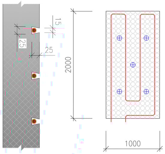 Figure 12. Principle of a panel with ATP (water as the heat-transfer medium)—by milling of grooves (on the left) Principle of a panel with ATP (water as the heat-transfer medium)—embedding into a system board (on the right) (author: Kalús) [3,13,14].
 - By embedding into a system board, see Figure 12 (on the right).
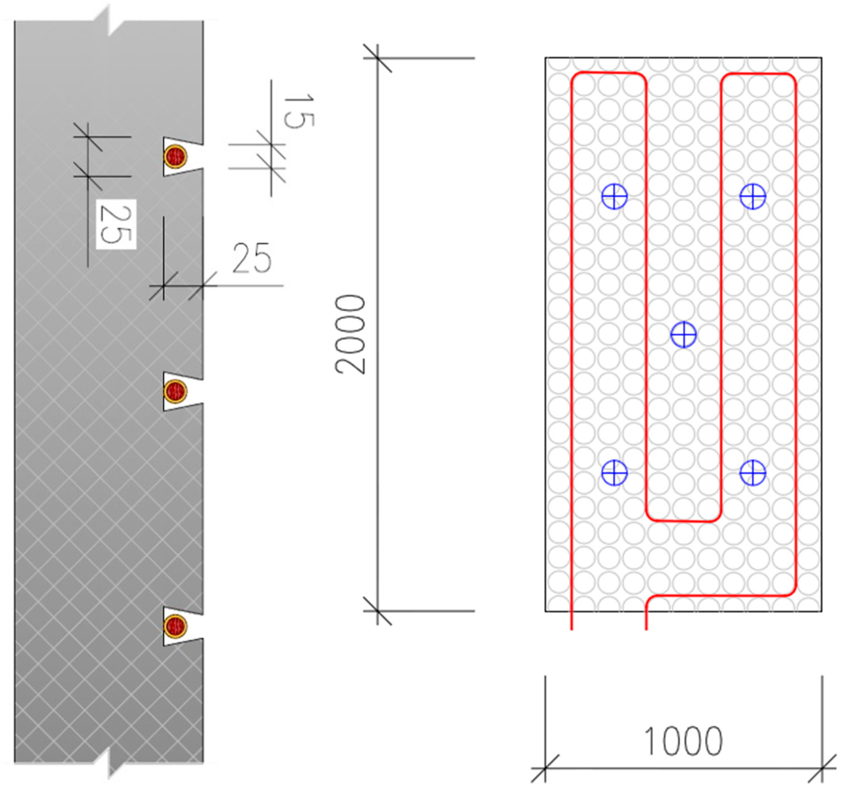
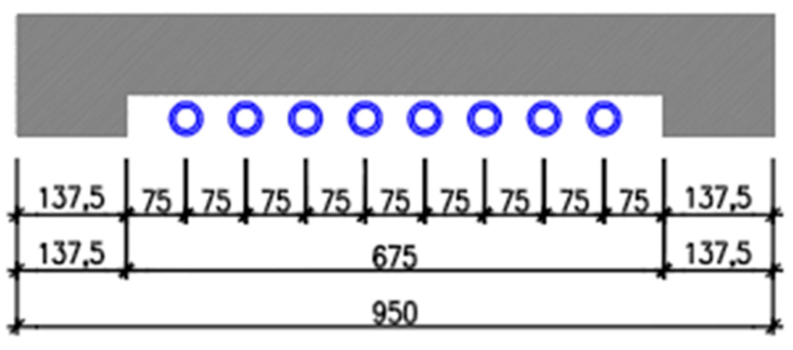
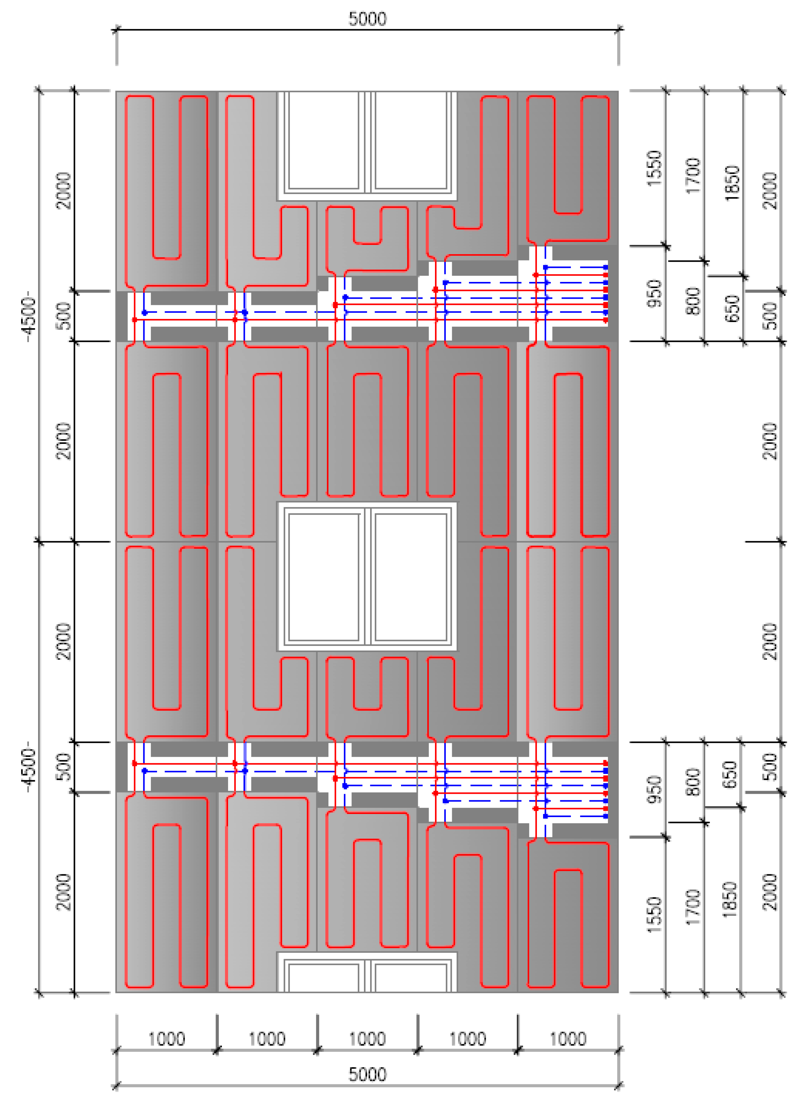
A contact thermal insulation system with ATP differs from classic thermal insulation systems because it contains distribution pipes. Connection of the panels to the supply and return pipes is realized in a way that none of the circuits created by the panels has an area bigger than 15 m2. The supply and return distribution pipes are led in canals [in panels] with standard dimensions of 1000 × 500 × thickness of the panels (minimum 100 mm), 1000 × 650 × thickness of the panels (minimum 100 mm),1000 × 800 × thickness of the panels (minimum 100 mm), 1000 × 950 × thickness of the panels (minimum 100 mm), see Figure 13. The principle of connection of the panels with ATP is shown in Figure 14.
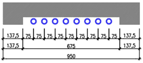
Figure 13.
Example of a thermal insulation panel to cover the supply and return pipes (author: Kalús) [3,13,14].
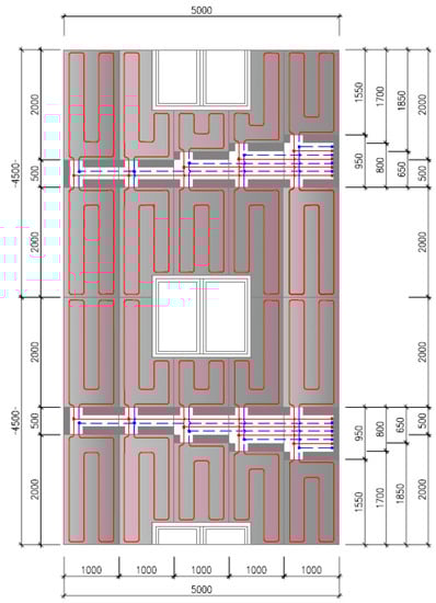
Figure 14.
Principle of connection of panels to heating circuits, supply and return distribution pipes led in canals (water as the heat-transfer medium) (author: Kalús) [3,13,14].
5. Discussion
Realization of active thermal protection (ATP) according to previously known systems, e.g., ISOMAX is carried out in several technological steps. First, the piping systems are anchored to the walls. In the next step, the pipes are plastered. This is followed by a technological break of 28 days needed to “mature” the plaster. Then the thermal insulation is applied to the walls only by gluing without anchoring with plate dowels, so that the piping is not broken. Finally, the top layers of the facade are applied.
The innovativeness of the facade system with active thermal protection is presented by the integration of the piping system into the thermal insulation panels of classic thermal insulation systems, e.g., from expanded polystyrene (EPS). Active thermal protection (ATP) is implemented in the same way as a conventional thermal insulation system, without unnecessary technological steps: anchoring the piping system to the walls, plastering the piping system, and without unnecessary technological breaks to “mature” the plaster. Another benefit is the possibility of anchoring with plate dowels due to the marking of the pipeline in the thermal insulation panels. Such a solution provides time but also financial savings compared to previous methods of implementing active thermal protection.
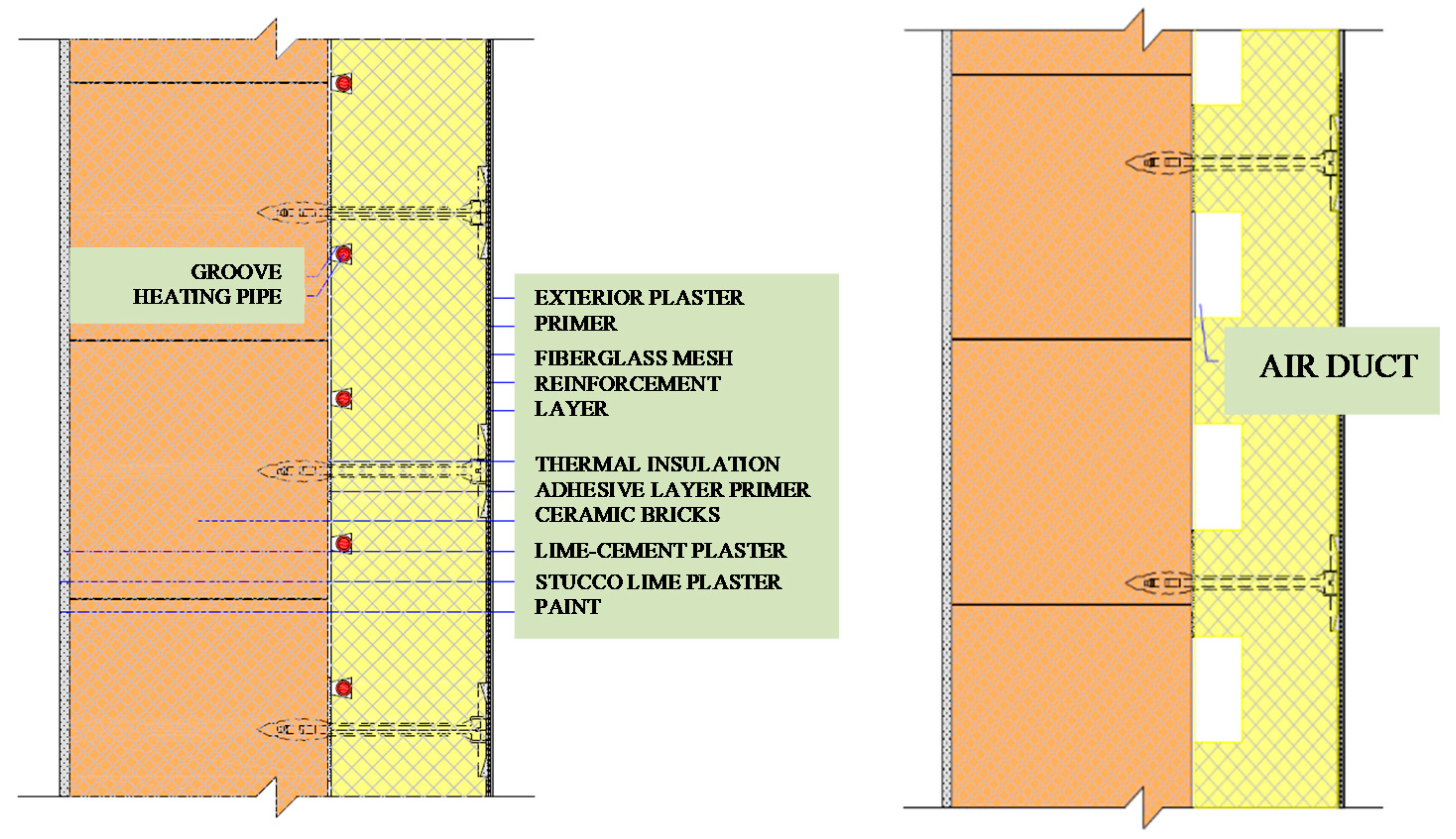
The innovative facade system with active thermal protection allows various combinations of the use of energy systems, renewable energy sources and heat transfer agents, as shown in Figure 15, Figure 16 and Figure 17.
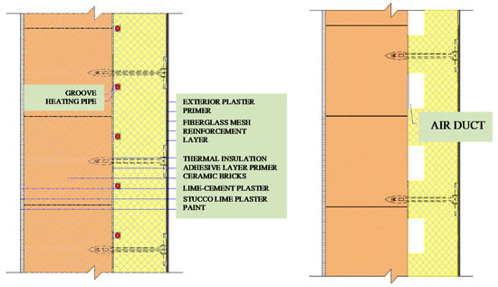
Figure 15.
Application of contact heat insulating panel with active regulation of heat transition carrier water or air (author: Kalús) [3,13,14].
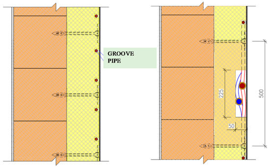
Figure 16.
Application of the contact insulation system with a collector collecting solar energy or energy of the surrounding environment, in combination with heat pump (author: Kalús) [3,13,14].
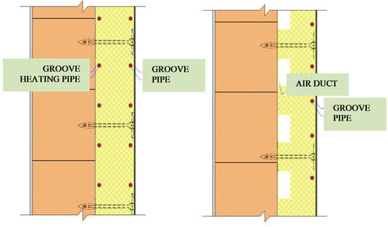
Figure 17.
Application of the contact insulation system by means of thermally active panels, with a combined function of ATP and register collecting solar energy or energy of the surrounding (author: Kalús) [3,13,14].
The technical solution of thermal heat insulating panels with active regulation of heat transition was described in the European patent specification number EP 2 572 057 B1 published in the Bulletin of the European Patent Office 2014/42, 15.10.2014, [13]. Technology applies to the invention of heat-insulating panel with active thermal protection (ATP) and its heat transition regulation used in panel buildings, new or existing ones being renovated. The construction mentioned above is a part of prefabricated light external cladding which together with low-temperature heating and high-temperature cooling systems creates indoor environment. The energy source is usually renewable or technological waste heat. The invention falls within the area of building industry. The technology presented in this document is mainly based on this patent.
The thermal and cooling performance of thermal insulation panels with ATP depends on several factors: thickness of thermal insulation, thickness of load-bearing part of walls and their material (good thermal conductivity is required), axial distance of pipes, pipe dimensions, mean heat transfer medium temperature, heat storage capacity/cold material of building structures with ATO. The calculation procedure is the same as for the design of low-temperature radiant heating/high-temperature cooling systems.
The expected service life and maintenance of the combined building-energy system with thermal insulation panels with ATP is the same as the service life and maintenance of conventional thermal insulation systems and low-temperature radiant heating/high-temperature cooling systems.
The expected price of a combined building-energy system with thermal insulation panels with ATP will be lower than the total price of a classic thermal insulation system and low-temperature radiant heating/high-temperature cooling systems implemented in the building separately.
From the perspective of sustainability, it can be stated that the association of producers and processors of expanded polystyrene is aware of the growing pressure by the EU for more efficient use of plastics and reducing their negative effect on the environment. The association has also joined the voluntary commitment of the European Association of EPS Manufacturers and Processors (EUMEPS), which has voluntarily committed itself to ensuring the full circulation of EPS by 2030 under the Plastics Strategy [32].
The checkpoint is to be 2025, when EUMEPS has set itself the goal of recycling at least 46% of the total amount of EPS (expanded polystyrene) produced in the territory of its member countries. It is committed to demonstrating that the EPS industry can be economically, socially and environmentally beneficial and sustainable [32].
Therefore, it is not likely that building regulations in European countries prevent the use of polystyrene in thermal insulation systems.
In terms of fire safety, the National levels of the EU are developed for thermal insulation system applying EPS technical standards and decrees. Within the Slovak Republic, it is generally valid in terms of Fire Protection decree MV SR no. 94/2004 Z.Z laying down technical requirements for fire safety in construction and use of buildings. Following the increase in ETICS thickness applies to the Slovak Republic since 2015 revised standard [33] which takes into account the design of ETICS, in particular with regard to the fire amount and the related designs of ETICS details. The invention will be applied in terms of them.
5.1. Thermal Insulation Panels with Active Regulation of Heat Transfer with Integrated Active Area—Register for Heating and Cooling with Liquid or Gas as the Heat Carrier
The character of low temperature heating and high temperature cooling applied into the constructions with ATP also designates this system for the application into industrial buildings, commercial premises and other civic amenities, where, besides the traditional heat sources, it is possible to use renewable energy sources and waste heat, e.g., from cooling and freezing installations. The versatility of application to all types of buildings or premises is supported by the possibility to use the ATP panels also with air as the heat carrier, shown in Figure 15 (on the left). Panels with air heat carrier can be manufactured with plastic (metal) air-conditioning ducts with a circular cross-section with the diameter of 50 to 100 mm, integrated into the insulation board.
5.2. Thermal Insulation Panels with Active Regulation of Heat Transfer with Integrated Active Area—Register Collecting Solar Energy and Energy of the Surrounding Environment, with Liquid or Gas as the Heat Carrier
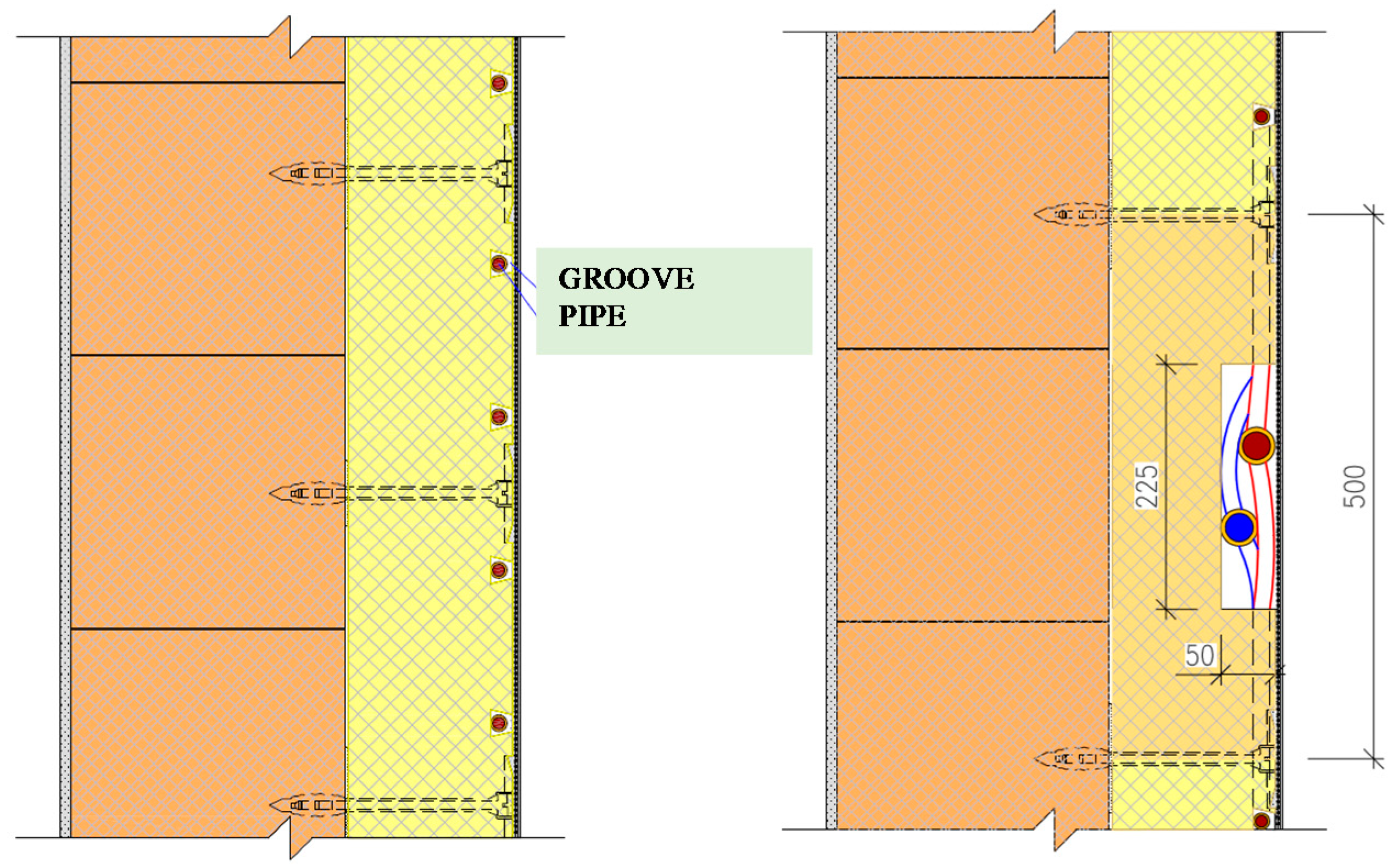
Thermal insulation panels with active regulation of heat transfer with integrated active area—register collecting solar energy or energy of the surrounding environment—are applied as a standard contact insulation system. The active area—formed by the pipes for liquid or gaseous heat carrier—is characteristic of the exterior surface. These thermally active panels are applied in combination with renewable heat sources, shown in Figure 16.
5.3. Thermal Insulation Panels with Active Regulation of Heat Transfer with the Function of ATP (Heating and Cooling) and Active Area—Register Collecting Solar Energy and Energy of the Surrounding Environment, with Liquid or Gas as the Heat Carrier
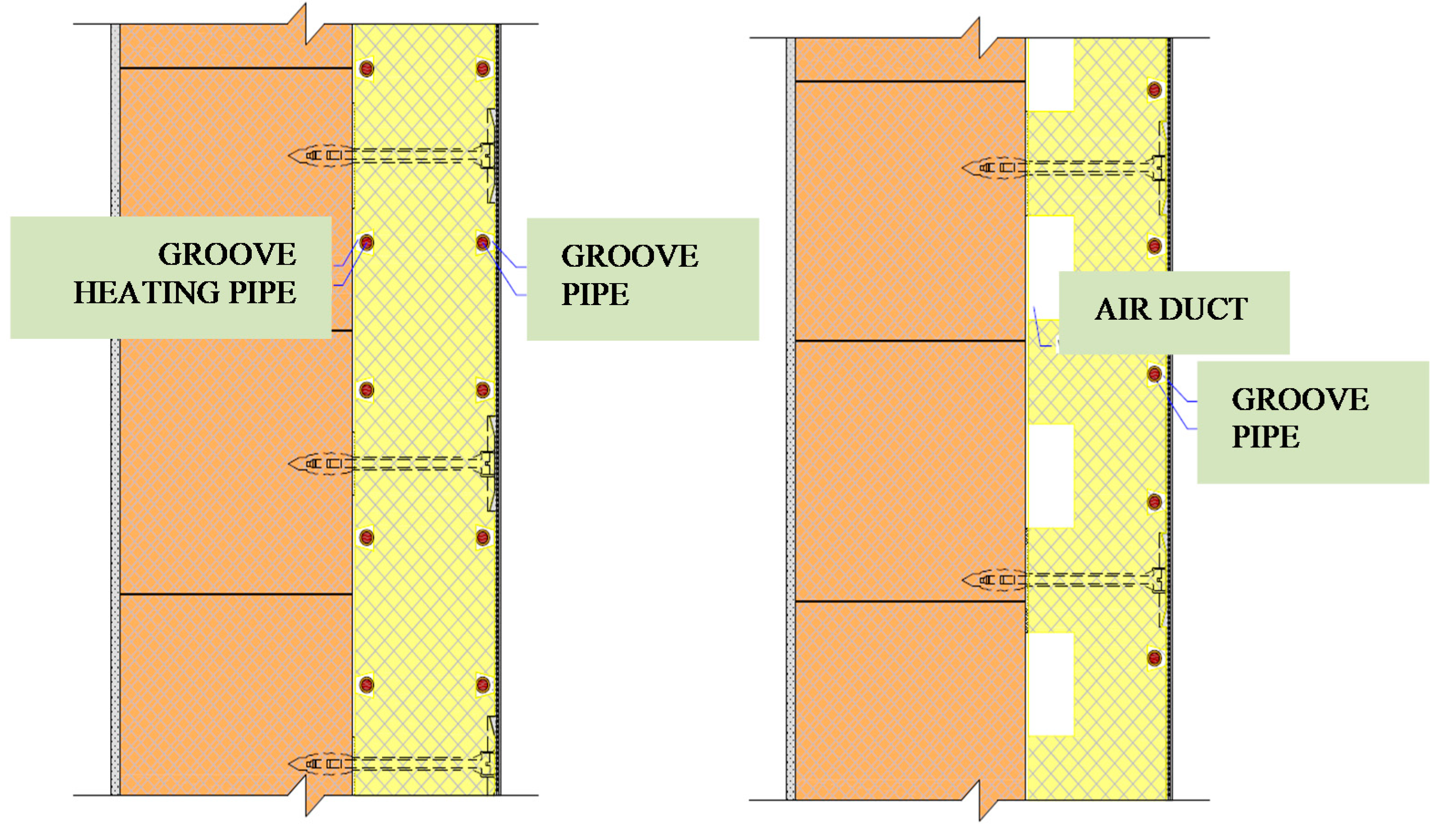
Combination of a thermal insulation panels with active regulation of heat transfer with ATP with an integrated active area (heating and cooling) presents another possibility of creating a compact insulation system, shown in Figure 17. In this category are contained insulation panels with ATP (water as the heat carrier or air with an additional function of absorber on the exterior side to collect energy of the surrounding environment). Thereby, the multiple functions of the construction and the contact insulation system are expanded, and at the same time the number of operations in the process of construction of a building and realization of an energy system is decreased. The simplicity and technologic process of realization of the combined facade system remains unchanged, as before.
6. Conclusions
The thermal insulation panels with active regulation of heat transfer with ATP have a wide range of application. The application these panels is most suitable for buildings with load-bearing parts of building constructions made of materials with good thermal conductivity and heat accumulation (e.g., reinforced concrete and solid fired brick). Not only new buildings, but also reconstructions are concerned. The idea of unification of the production is supported by the fact that majority of apartment houses in Slovakia, in central and Eastern Europe are not yet insulated. Elaboration of prototypal documentation with laying plans for the respective types of panel apartment buildings could significantly contribute to mass production of the panels with ATP. The character of low temperature heating applied to constructions with ATP designates this system also for application to industrial buildings, commercial premises and other civic amenities, where, besides the traditional heat sources, it is possible to use renewable energy sources and waste heat, e.g., from cooling and freezing installations. The versatility of application to all types of buildings or premises is supported by the possibility to use the ATP panels also with AIR as the heat carrier. Panels with AIR as the heat carrier can be manufactured with plastic (metal) air-condition ducts with a circular cross-section with the diameter of 50 to 100 mm, integrated in the insulation board.
The simplicity of the integration of piping systems into the thermal insulation panels of conventional thermal insulation systems was proved by the manufactured prototypes, which are shown in Figure 9. The trouble-free and low-cost production of unified prefabricated parts with integrated piping systems has been confirmed by the manufacturers of thermal insulation systems. The innovative facade system with active thermal protection represents a multifunctional building and energy solution with a high potential for the use of renewable energy sources, the required low energy consumption and high economic efficiency. It represents sustainable and environmentally friendly development concepts in construction and energy.
The biggest limitation of the implementation of this technology in practice can be considered the fact that thermal insulation panels with ATP have not yet been certified and manufactured by any manufacturer. We recommend further research, especially toward multifunctional thermal insulation panels with ATP which work as low-temperature radiant heating/high-temperature cooling systems, but also as an absorber of solar energy and ambient energy in cooperation with heat pumps.
Author Contributions
Conceptualization, M.K. and P.Š.; methodology, D.K., J.G., P.J. and P.Š.; software, D.K.; validation, D.K.; formal analysis, D.K., J.G., P.J. and M.K.; investigation, D.K., J.G., P.J. and M.K.; resources, D.K.; data curation, D.K., J.G., P.J., M.K. and P.Š.; writing—original draft preparation, D.K., M.K. and P.Š.; writing—review and editing, P.Š.; project administration, D.K., J.G. and P.Š. All authors have read and agreed to the published version of the manuscript.
Funding
This paper was created as a research work for the project VEGA N. 1/0511/19.
Conflicts of Interest
The authors declare no conflict of interest.
References
- Directive (EU) 2018/844 of the European Parliament and of the Council of 30 May 2018 amending Directive 2010/31/EU on the Energy Performance of Buildings and Directive 2012/27/EU on Energy Efficiency. Available online: https://eur-lex.europa.eu/legal-content/EN/TXT/?uri=uriserv%3AOJ.L_.2018.156.01.0075.01.ENG (accessed on 14 March 2021).
- Šimko, M.; Krajčík, M.; Šikula, O.; Šimko, P.; Kalús, D. Insulation panels for active control of heat transfer in walls operated as space heating or as a thermal barrier: Numerical simulations and experiments. Energy Build. 2018, 158, 135–146. [Google Scholar] [CrossRef]
- Kalús, D.; Šimko, M.; Galváneková, M. Intelligent Facade System with Active Thermal Protection; Scholars’ Press: Stuttgart, Germany, 2014; p. 56. [Google Scholar]
- Krajčík, M.; Šikula, O. The possibilities and limitations of using radiant wall cooling in new and retrofitted existing buildings. Appl. Thermal Eng. 2020, 164, 114490. [Google Scholar] [CrossRef]
- Krajčík, M.; Šikula, O. Heat storage efficiency and effective thermal output: Indicators of thermal response and output of radiant heating and cooling systems. Energy Build. 2020, 229, 110524. [Google Scholar] [CrossRef]
- Oravec, J.; Šikula, O.; Krajčík, M.; Müslüm, A.; Mohapl, M. A comparative study on the applicability of six radiant floor, wall, and ceiling heating systems based on thermal performance analysis. J. Build. Eng. 2021, 36, 102133. [Google Scholar] [CrossRef]
- Krajčík, M.; Šikula, O. The possibilities of application of radiant wall cooling in existing buildings as a part of their retrofit. E3S Web Conf. 2019, 111, 7. [Google Scholar] [CrossRef]
- Tunçbileka, E.; Müslüm, A.; Krajčík, M.; Nižetić, S.; Karabay, H. Thermal performance based optimization of an office wall containing PCM under intermittent cooling operation. Appl. Thermal Eng. 2020, 179, 115750. [Google Scholar] [CrossRef]
- Zhu, Q.; Xu, X.; Gao, J.; Xiao, F. A semi-Dynamic simplified therm model of active pipe embedded building envelope based on frequency finite difference method. Int. J. Thermal Sci. 2015, 88, 170–179. [Google Scholar] [CrossRef]
- Christlieb, X.W. Gestión Térmica de una Vivienda con Mínimo Consumo de Energía–Proyecto de Fin de CARRERA; Universidad Pontificia Comillas: Madrid, Spain, 2007. [Google Scholar]
- Krzaczeka, M.; Kowalczuk, Z. Thermal Barrier as a technique of indirect heating and cooling for residential buildings. Int. J. Devoted Investig. Energy Use Effic. Build. Energy Build. 2011, 43, 823–837. [Google Scholar] [CrossRef]
- Babiak, J.; Olesen, B.W.; Petráš, D. Low Temperature Heating and High Temperature Cooling; Guidebook No 7; REHVA: Brussels, Belgium, 2007; p. 115. [Google Scholar]
- Kalús, D. EUROPEAN PATENT EP 2 572 057 B1: Heat Insulating Panel with Active Regulation of Heat Transition. In Bulletin 2014/42 European Patent Office, Slovak Republic. 2014; p. 67. Available online: https://wbr.indprop.gov.sk/WebRegistre/EPPatentPreSR/Detail/11716446.7 (accessed on 6 April 2021).
- Kalús, D. UTILITY MODEL SK 5725 Y1 (UTILITY MODEL): Tepelnoizolačný Panel pre Systémy s Aktívnym Riadením Prechodu Tepla. [Thermal Insulation Panel for Systems with Active Heat Transfer Control.] In Vestník ÚPV SR No.: 4/2011, Slovak Republic. 2011; p. 63. Available online: https://wbr.indprop.gov.sk/WebRegistre/UzitkovyVzor/Detail/5031-2010 (accessed on 6 April 2021).
- Krecké, E.D. Energetické Zariadenie Budov. [Energy Equipment of Buildings.] In Vestník ÚPV SR č.: 11/2005. Patent SK 284 751, 3 November 2005. [Google Scholar]
- ISOMAX. Available online: http://www.isomax.sk (accessed on 14 March 2021).
- Available online: http://www.isomax-terrasol.eu (accessed on 14 March 2021).
- ISOMAX–Technische Information. Available online: http://www.isomax-terrasol.eu/fileadmin/_migrated/content_uploads/ISOMAX-TerraSol-Technologie-DE.pdf (accessed on 6 April 2021).
- Cvíčela, M. Analysis of Wall Energy Systems. Master’s Thesis, Faculty of Civil Engineering, Slovak University of Technology in Bratislava, Bratislava, Slovakia, 2011; p. 119, SVF-13422-17675. [Google Scholar]
- Kalús, D.; Gašparík, J.; Janík, P.; Kubica, M.; Šťastný, P. Research Project HZ PG73/2011-Experimental Measurements, Analysis, and Determination of the Optimal Rate of Use of Renewable Energy Sources on a Prototype of a Family House EB2020 with Nearly Zero Energy Demand; Department of Building Services, Faculty of Civil Engineering, Slovak University of Technology in Bratislava: Bratislava, Slovakia, 2011–2013. [Google Scholar]
- Janík, P. Optimization of Energy Systems with Long-Term Heat Accumulation. Master’s Thesis, Faculty of Civil Engineering, Slovak University of Technology in Bratislava, Bratislava, Slovakia, 2013; p. 185, SvF-13422-16657. [Google Scholar]
- Petráš, D.; Lulkovičová, O.; Takács, J.; Füri, B. Nízkoteplotné Vykurovanie a Obnoviteľné Zdroje Energie; JAGA: Bratislava, Slovakia, 2001; p. 271. [Google Scholar]
- Petráš, D.; Lulkovičová, O.; Füri, B.; Takács, J. Nízkoteplotní Vytápění a Obnovitelné Zdroje Energie; JAGA Group: Bratislava, Slovakia, 2008; p. 216. [Google Scholar]
- STN 06 0312: Ústredné Sálavé Vykurovanie so Zabetónovanými Rúrkami. Projektovanie a Montáž. [Radiation Central Heating with Concreted Tubes. Projection and Installation]. Available online: https://normy.unms.sk/eshop/public/standard_detail.aspx?id=52393 (accessed on 6 April 2021).
- Kalús, D. UTILITY MODEL SK 5729 Y1 (UTILITY MODEL): Samonosný Tepelnoizolačný Panel pre Systémy s Aktívnym Riadením Prechodu Tepla. [Self-Supporting Thermal Insulation Panel for Systems with Active Heat Transfer Control.] In Vestník ÚPV SR No.: 4/2011, Slovak Republic. 2011; p. 32. Available online: https://wbr.indprop.gov.sk/WebRegistre/UzitkovyVzor/Detail/5030-2010 (accessed on 6 April 2021).
- Kalús, D. UTILITY MODEL SK 5749 Y1 (UTILITY MODEL): Spôsob Prevádzky Kombinovaného Stavebno-Energetického Systému Budov a Zariadenie. [Method of Operation of a Combined Construction-Energy System of Buildings and Equipment.] In Vestník ÚPV SR No.: 5/2011, Slovak Republic. 2011. Available online: https://wbr.indprop.gov.sk/WebRegistre/UzitkovyVzor/Detail/5027-2010 (accessed on 6 April 2021).
- Kalús, D. Research Project HZ 04-309-05-Design of a Passive House Using Solar and Geothermic Energy; Department of Building Services, Faculty of Civil Engineering, Slovak University of Technology in Bratislava: Bratislava, Slovakia, 2006. [Google Scholar]
- Kalús, D. Research Project HZ 04-310-05-Assessment of Thermal Comfort State in an Experimental House; Slovak Republic, Department of Building Services, Faculty of Civil Engineering, Slovak University of Technology in Bratislava: Bratislava, Slovakia, 2006. [Google Scholar]
- Kalús, D. Research Project HZ 04-142-07-Assessment of Thermal Comfort State in an Experimental House; Department of Building Services, Faculty of Civil Engineering, Slovak University of Technology in Bratislava: Bratislava, Slovakia, 2007. [Google Scholar]
- Kalús, D. Research Project HZ PR10/2015-Analysis of Energy, Economic, Environmental Aspects and Experimental Measurements of Compact Equipment of Energy Systems for the Application of Renewable Energy Sources; Department of Building Services, Faculty of Civil Engineering, Slovak University of Technology in Bratislava: Bratislava, Slovakia, 2015. [Google Scholar]
- Šimko, M. Energy Efficiency in Buildings with Systems with Active Thermal Protection. Master’s Thesis, Faculty of Civil Engineering, Slovak University of Technology in Bratislava, Bratislava, Slovakia, 2017; p. 152, SvF-13422-49350. [Google Scholar]
- Available online: https://www.asb.sk/stavebnictvo/zateplenie/expandovany-polystyren-pouzivany-na-zateplovanie-je-environmentalne-vhodny-material (accessed on 6 April 2021).
- STN 73 2901/01: Zhotovovanie vonkajších tepelno-izolačných kontaktných systémov ETICS. 2015. Available online: https://www.stavomat.com/--13-87-stn-73-2901-2015-zhotovovanie-vonkajsich-tepelnoizolacnych-kontaktnych-systemov-etics- (accessed on 6 April 2021).


Publisher’s Note: MDPI stays neutral with regard to jurisdictional claims in published maps and institutional affiliations. |
© 2021 by the authors. Licensee MDPI, Basel, Switzerland. This article is an open access article distributed under the terms and conditions of the Creative Commons Attribution (CC BY) license (https://creativecommons.org/licenses/by/4.0/).