Article

Constructability Analyses of Vertical Extension Methods for Existing Underground Spaces

1
School of Architecture, Korea National University of Transportation, Chungju 27469, Korea
2
Korea Construction Technology Consulting & Eng. Co., Ltd., Seoul 05544, Korea
*
Author to whom correspondence should be addressed.
Sustainability 2021, 13(7), 3647; https://doi.org/10.3390/su13073647
Submission received: 17 February 2021 / Revised: 22 March 2021 / Accepted: 22 March 2021 / Published: 25 March 2021

Abstract

:
Remodeling underground structures requires careful construction planning, including consideration of costs and scheduling. Therefore, this study aims to analyze and compare the effects of four methods for vertically extending the underground spaces of an existing building under scheduling and cost constraints. The study considers the following extension methods: (1) bottom-up method, (2) normal top-down method after demolition, (3) normal top-down method in parallel with demolition, and (4) top-down method using double beams in parallel with demolition. Twelve illustrative examples are presented to investigate the constructability of these methods in terms of construction scheduling and costs. The construction durations and costs of each example is calculated and compared. We also analyze the structural stability of the examples using MIDAS Gen 2017. We conclude that the top-down method using double beams is the most efficient method in terms of costs and scheduling. The results and analysis process can help practitioners to select appropriate methods to expand underground spaces without demolishing entire existing buildings and efficiently manage costs and schedules. In future studies, these extension methods should be applied to real-world projects in various countries to validate and verify their actual effects on construction costs and scheduling.

1. Introduction

Urban area populations are growing rapidly worldwide and the availability of space in congested urban areas is decreasing [1]. Therefore, underground spaces beneath buildings are increasingly utilized [2,3,4,5]. To make use of such spaces, stable structures are often dismantled and then reconstructed in the same location. However, demolition and reconstruction of buildings incur enormous costs as well as leading to other problems such as environmental pollution and complaints [6]. Therefore, remodeling and renovation processes in the architecture, engineering, and construction (AEC) industry are typically preferred as alternatives. Remodeling underground structures has more significant impacts in terms of the environment, costs, and scheduling than remodeling superstructures [5,7]. Therefore, remodeling work on underground structures requires more careful construction planning, considering both costs and scheduling. The underground space below an existing building can be vertically and horizontally expanded to improve functionality without demolishing the entire building. However, underground vertical extension is more complicated and requires a higher level of technology skill than either underground horizontal extension or new construction in general, and there are few previous studies and example cases of methods for increasing the number of floors in underground spaces. Related studies can be categorized into two main groups: (1) case studies on extending underground spaces below existing buildings [8,9,10,11] and (2) processes to vertically extend underground spaces of existing buildings [12,13,14]. Bing [9] investigated a case to vertically extend underground spaces of residential buildings, which were used for parking lots. However, specific processes for vertically extending existing underground spaces were not proposed. Park, Lew, Choi, and Lee [12] proposed a process to vertically expand underground space and applied it to a real-world project in South Korea. The detailed application process and pros and cons of the method were introduced. Kim, Lee, Kim, Koo, Jung, and Seo [13] and Jung, Kim, Lee, Hwang, and Seo [14] suggested a new process to vertically extend underground spaces in existing buildings, as well as a process to determine the most appropriate method by considering project characteristics. However, they did not analyze the cost perspective of the proposed processes in depth. Therefore, Seo et al. [15] analyzed the structural stability as well as cost perspective of several vertical underground extension methods without demolishing entire existing buildings. They concluded that the top-down method with multiple posts downward was the most beneficial method, outperforming both the bottom-up and normal top-down methods under the same conditions. However, to expand underground spaces effectively, not only the cost perspective but also the scheduling perspective should be considered. Therefore, this study aims to analyze and compare the constructability, including construction costs and scheduling, of the four vertical underground extension methods in existing structures considering the amount of demolished and used building materials and the required number of laborers on site. The analyzed extension methods are the bottom-up method, normal top-down method after demolishing existing substructures, normal top-down method in parallel with demolition, and top-down method using double beams in parallel with demolition. To analyze impacts on cost and schedule management, we considered 12 illustrative examples. The four vertical underground extension methods in established buildings were applied to these examples for calculation and comparison.

2. Research Methodology

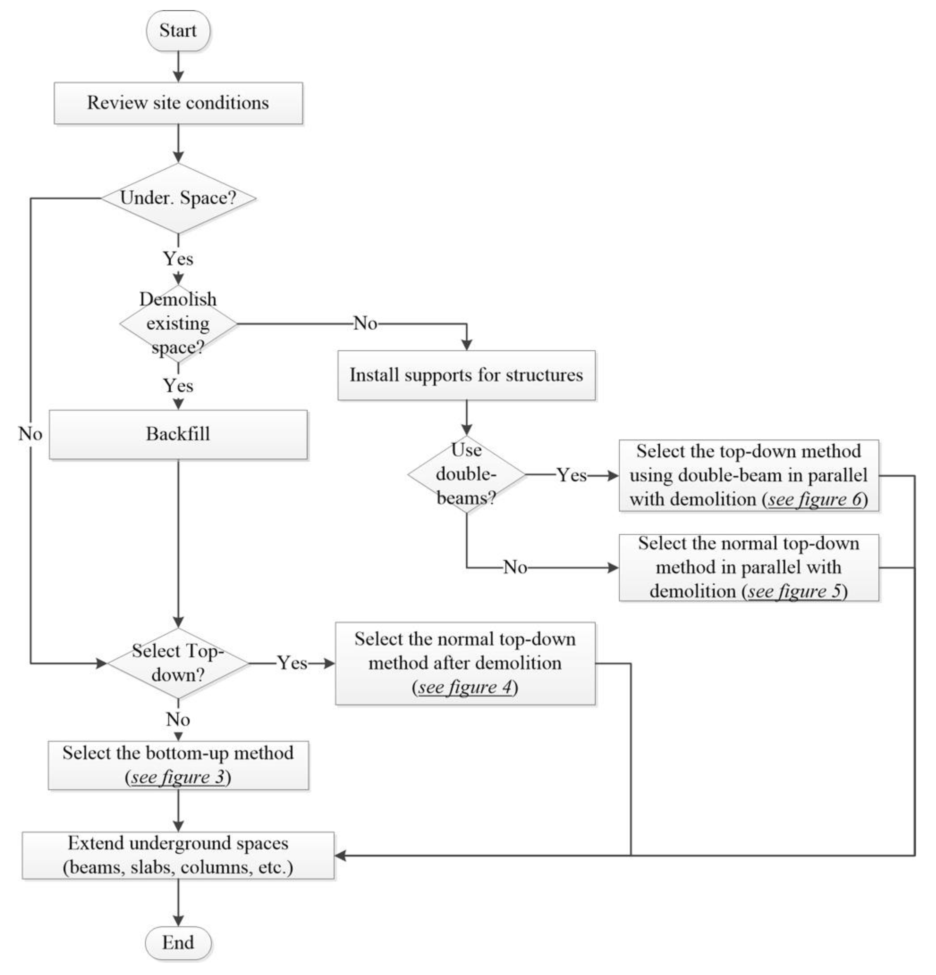
Figure 1 presents a research flow for analyzing costs and scheduling of the four underground vertical extension methods. The four methods considered in this study can be summarized as below.
(1)
Bottom-up method: all of the excavation of soil under an existing structure should be completed before vertical underground space extension is performed.
(2)
Normal top-down method after demolition of existing underground structures: prior to the construction of structural frames of each basement floor in the substructure, soil with volume corresponding to height of one basement level should be excavated below the floor under the existing structure. These demolition and construction processes are repeated until reaching the desired number of floors.
(3)
Normal top-down method in parallel with the demolition of existing underground structures: the construction of structural frames of each extended floor is carried out while supporting and demolishing existing underground structures and the other processes are the same as those in the normal top-down method after demolition.
(4)
Top-down method using double beams in parallel with the demolition of existing underground structures: the construction process of this method is very similar to the top-down method in parallel with demolition, but this method uses double beams to support the existing building and installs structural frames for extended underground structures.
The process of vertically extending the underground spaces without demolishing entire existing buildings is complicated because we must consider construction costs, scheduling, and structural stability issues simultaneously. Section 3 discusses the detailed processes of the four extension methods listed above. To analyze the effects of these four methods on construction costs and durations, 12 illustrative examples were created in this study with the number of extended basement floors and underground vertical extension methods as variables in Section 4. Prior to conducting cost and scheduling analyses of the methods, we analyzed the structural stability of examples using MIDAS Gen 2017 in Section 5. This software has been widely used for structural analysis in South Korea because its reliability has been verified in previous studies [16].
The constructability of the 12 illustrative examples was analyzed by considering both cost and scheduling perspectives, as shown in Section 6. Cost and scheduling analysis were calculated based on the quantity of construction materials and equipment used in each work. Vertical underground extension processes typically include preparation, support installation, demolition and backfill work, retaining walls, pile work, percussion rotary drills (PRDs), temporary post work, strut and excavation work, top-down excavation work, foundation work, structural frame construction, finish work, inspection, and miscellaneous work. The durations of each type of work and relevant construction coefficients were determined by experts based on construction plans, calculated quantities, and labor and equipment productivities [17]. The working experience of the experts was approximately 20 years. The processes to analyze the underground vertical extension costs in this paper are similar to those of Seo et al. [15]. To estimate the costs of the four methods, the calculated quantities and itemized unit costs for several types of work in each construction method were determined based on expert opinions and the construction cost calculation ratio standard provided by the Public Procurement Service (PPS) in South Korea. Material and labor costs, miscellaneous expenses, general administrative expenses, profit, and value-added tax (VAT) were also calculated. The details of the assumed and calculated construction durations and costs are described in Section 6. Lastly, discussion and conclusions are provided in Section 7.

3. Underground Vertical Extension Methods

The constructability of the four underground vertical extension methods in existing buildings was analyzed in this paper. They were the bottom-up method, normal top-down method after demolition, normal top-down method in parallel with demolition, and top-down method using double beams in parallel with demolition. When carried out in parallel with demolishing existing substructures, top-down methods can also be used for vertical underground extension. In this paper, the normal top-down method and top-down method using double beams were considered as top-down methods in parallel with demolition.
In congested urban areas, the top-down method is generally used to improve structural stability of retaining walls, to create available work spaces on basement floors, and to reduce construction durations [2,18]. Temporary or permanent columns should be constructed in the ground ahead of the excavation process to utilize the top-down method for vertically extending existing underground structures. Generally, after demolishment of the existing substructures, the columns are installed to improve their constructability. PRDs are typically used to install columns. However, PRDs have large diameters and their construction costs are relatively large. In contrast, the top-down method using double beams utilizes supports to reinforce existing underground structures and then installs retaining walls and temporary posts. Double-beam systems can reduce the section sizes of steel beams, the amount of steel used, and the heights of basement floors. In particular, the top-down method using double beams might be more efficient for downward vertical expansion in underground spaces because it can reduce the height of extended basement floors. Additionally, the dismantled temporary posts are reusable. The bottom-up method is the most common method. An open-cut method using temporary struts is widely used for retaining walls if the bottom-up method is applied on site. However, this method has several challenges, such as collapse of retaining walls and negative impacts on nearby buildings. Therefore, a thorough approach considering structural safety of the structures should be established when dismantling the installed temporary struts. In general, the top-down method is regarded as a safe option for constructing substructures with excavation.
To determine an appropriate underground vertical extension method by reviewing geological conditions on site and a number of drawings, the following project characteristics should be considered [19]: the number of basement floors in an existing building, the number of basement floors to be extended, whether workspaces on the ground floor are available during construction, whether retaining walls can be constructed, retaining walls type, soil conditions, and foundation type of existing substructures. The process to select an appropriate method for vertically extending underground spaces is illustrated in Figure 2.
Because the net distance between the outer walls of an existing underground structure and adjacent buildings should be sufficient for constructing retaining walls, the distance should be at least 1.2 m in South Korea [20]. Therefore, it is assumed in this paper that the net distance is greater than 1.2 m and that retaining walls are installed inside the existing substructure.

3.1. Bottom-Up Method

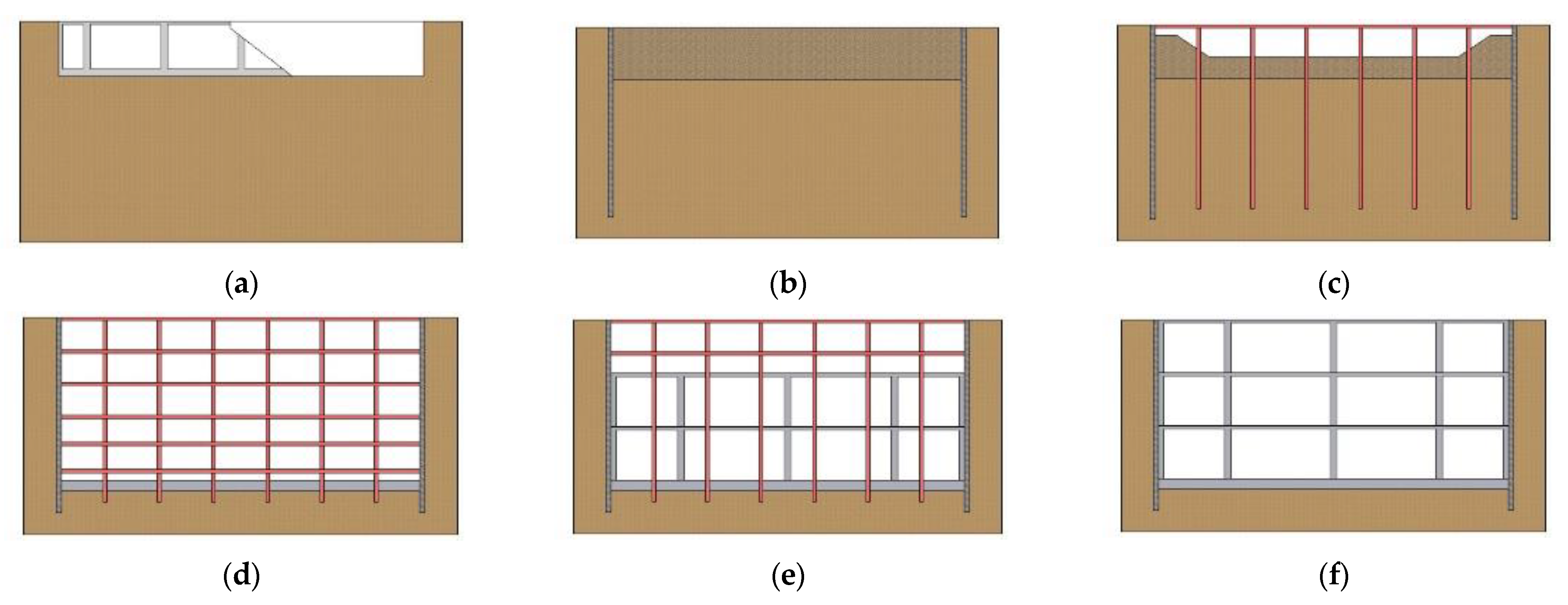
Underground extension by the bottom-up method requires the completion of excavation work up to the foundation depth with reinforcement of the struts prior to the installation of structural frames of substructures. The underground extension process of the bottom-up method is illustrated in Figure 3. After demolishing entire existing basement floors and backfilling (Figure 3a,b, respectively), the substructure can be reconstructed, thereby vertically expanding the underground space. Retaining walls are installed, and then temporary struts and H-piles are set up to guarantee the structural safety of the substructures during excavation (Figure 3c). Struts are installed at 2.5 m vertical interval. Structural frames of extended substructures are constructed from the foundation to the ground level repeatedly (Figure 3d). If all of the structural frames are constructed, H-piles and struts are finally dismantled (Figure 3e). Figure 3f represents the underground structure that has been extended by the bottom-up method.

3.2. Normal Top-Down Method after Demolition

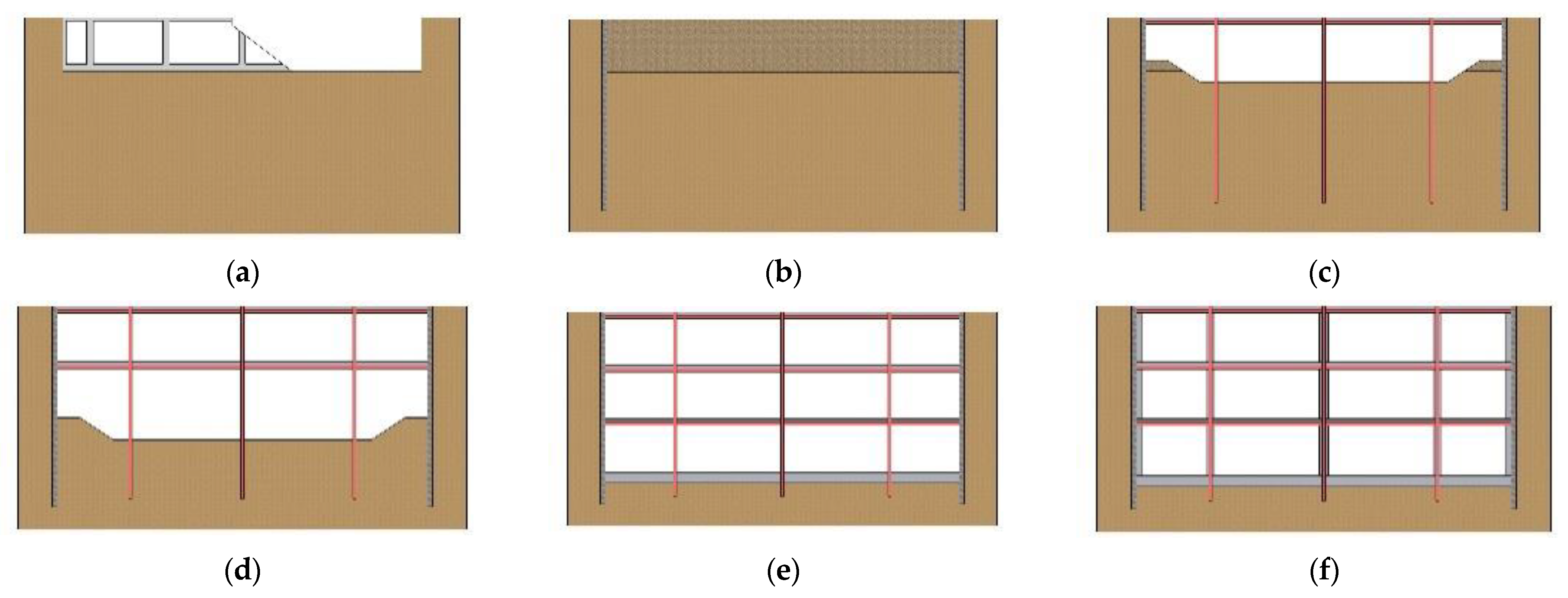
Figure 4 illustrates the process of demolishing existing substructures and then vertically extending underground spaces applying the top-down method. The method requires the process to construct structural frames in underground spaces from basement first floor (B1F) level to basement third floor (B3F) and the foundation level [21] (Figure 4d–f). Retaining walls are supported by the constructed structural frames, including slabs and beams, without additional temporary struts [13]. This method helps to efficiently manage construction costs and scheduling since available work spaces are provided for laborers on the constructed slabs [13], as shown in Figure 4c,d. In contrast, vertical underground extension, in which the bottom-up method is applied, requires the reinforcement of existing substructures with H-piles and struts to tolerate the weight of used construction equipment.

3.3. Normal Top-Down Method in Parallel with Demolition

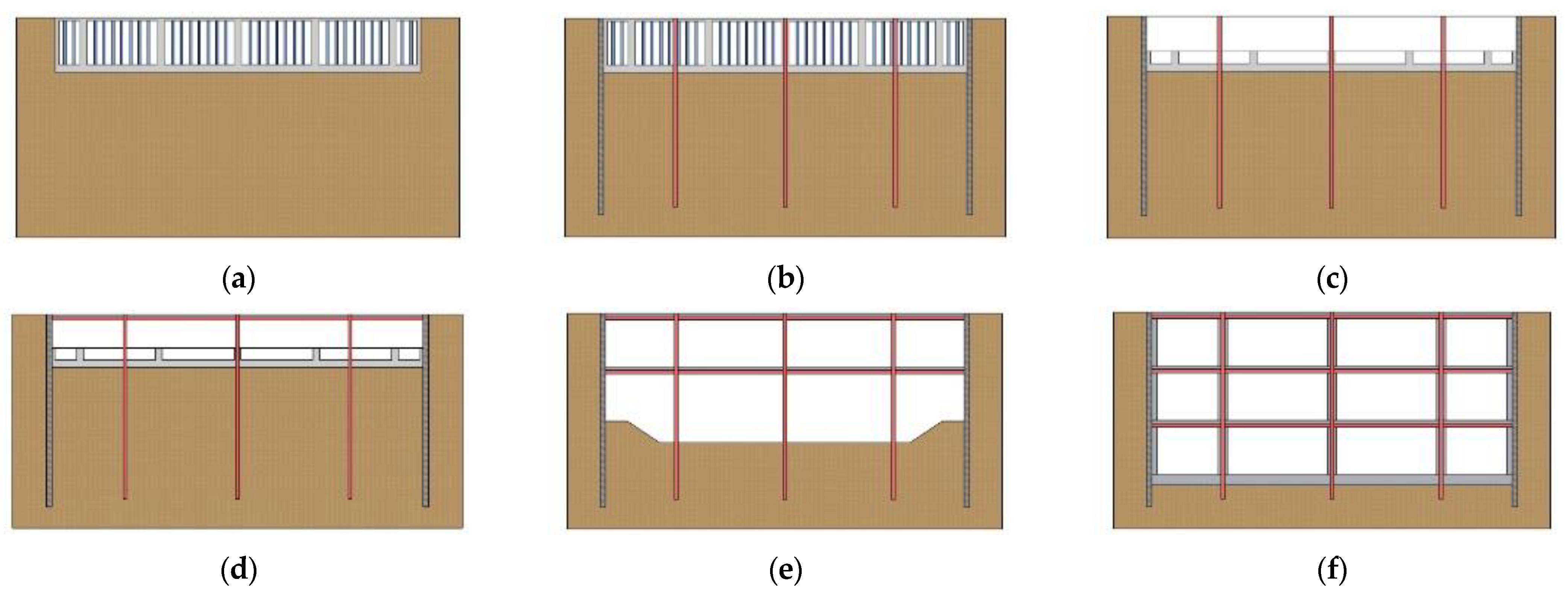
The normal top-down method can also be applied for vertically extending underground spaces in parallel with demolition of existing substructure. Figure 5 illustrates the vertical underground extension process of the normal top-down method in parallel with demolition. To utilize the normal top-down method in parallel with demolition, one should install supports to reinforce existing basement floors (Figure 5a) before constructing retaining walls and PRDs (Figure 5b), unlike the normal top-down method after demolition. The other construction processes of the normal top-down method in parallel with demolition are similar to the normal top-down method after demolition as shown in Figure 5c–f.

3.4. Top-Down Method Using Double Beams in Parallel with Demolition

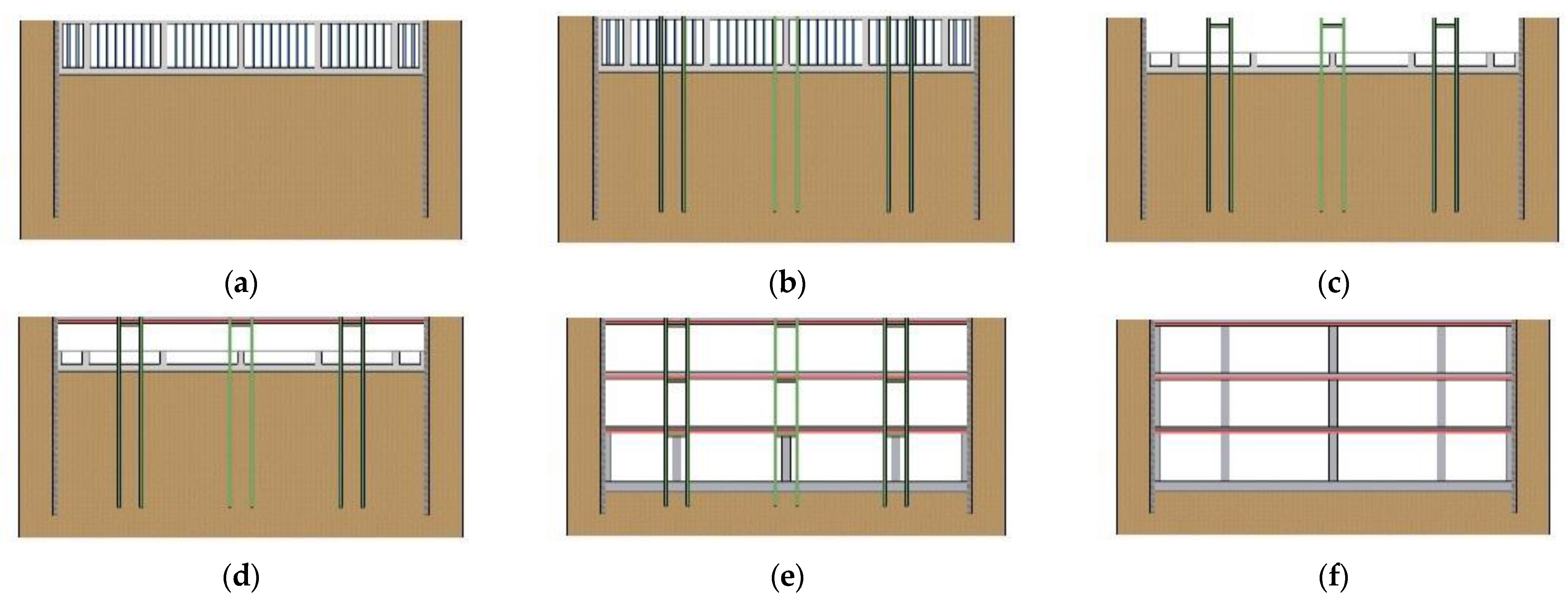
A process for vertically extending underground spaces of existing buildings using the top-down method with double beams in parallel with demolition is illustrated in Figure 6. When the top-down method using double beams is applied, the processes for installing supports and retaining walls are the same as those in the normal top-down method in parallel with demolition (Figure 6a). To avoid the collapse of columns in existing underground structures during excavation, it is required to install temporary posts instead of PRDs to support loads during construction, as shown in Figure 6b. Two or four temporary posts are installed around one column. After the extension process is completed, these posts can be removed and reused in other projects. Slabs, beams, and columns on the first basement floor of existing underground structures are partially demolished and girders for supporting double beams are installed (Figure 6c). The support girders of double-beam systems consist of two rows of steel beams. The details of double-beam systems are explained in the paragraph above Figure 7. Deck plates are placed on top of the installed double beams to construct slabs on the ground floor (Figure 6d).
Prior to dismantling temporary posts and girders (Figure 6f), new foundations and columns in the extended substructures should be constructed (Figure 6e). The top-down method using double beams helps reduce the amount of steel and height of basement floors because the steel beams are smaller than those used in the other methods.
Figure 7 illustrates the detailed construction process for applying the double-beam system. As shown in Figure 6b,c, temporary supports and girders for supporting double beams should be installed before installing double beams on the constructed girders and brackets (Figure 7c). Slabs are then constructed on the installed double beams and brackets (Figure 7d). Additional structural frames, such as reinforced concrete (RC) columns, are constructed on the basement floor and the installed temporary elements, including posts and girders, are dismantled.

4. Overview of Illustrative Examples

To analyze differences in cost and scheduling among the four extension methods, structural analysis, design, and process analyses were conducted for illustrative example building. An actual residential building in South Korea that would be remodeled and vertically expanded was determined as a case to create illustrative examples.
The building has one basement floor with 75 car parking spaces with dimensions of 5.5 × 5.2 m, as shown in Table 1. The example building was considered for expansion of underground spaces from B1F to B3F, basement fourth floor (B4F), or basement fifth floor (B5F). The remodeled building includes 59 car parking spaces with dimensions of 7.8 × 9.0 m in each extended basement floor. The module size of the parking spaces was updated according to the revised enforcement regulations for parking lots in South Korea.
Every example has one basement floor before extending underground spaces. As shown in Table 2, 12 illustrative examples were created through considering types of vertical underground extension methods, structure types, and the number of extended basement floors (from B3F to B5F). Each vertical extension method has three illustrative examples (extending to B3F, B4F, and B5F). The structure type of the bottom-up method is RC and those of the normal top-down method after demolition, in parallel with demolition, and using double beams are steel frames.

5. Structural Analysis

This study also analyzed the structural stability of the 12 illustrative examples. We used MIDAS Gen 2017 to analyze the structural stability in phases during the demolishing of the existing basement floor, excavating to the lowest level, and constructing structural frames of the extended substructure. The designed structural members can be classified into two types. The first one consists of members for securing the safety of the entire structures after completing extension of the substructures. The other type consists of members for guaranteeing structural safety in the demolition, excavation, and construction stages. If the bottom-up method is applied, excavation to the lowest floor level of extended underground spaces should be finished prior to construction of structural frames of the extended underground structure. Therefore, the structural stability of the extended RC substructure was checked.
This paper assumed the ground condition to be sandy soil in the 12 illustrative examples. We designed the examples so that there were installed temporary supports with 1.5 m intervals in the empty underground spaces. This ensures structural safety of the existing underground space when construction equipment is placed on the ground floor. Since building materials can be placed and stored on the ground floor, the live loads acting on the ground floor and basement floors were assumed to be 20.0 kN/m2 and 1.5 kN/m2 during construction, respectively. On the other hand, after completion, the live load on the ground floor and basement floor were 5.0 kN/m2 and 3.0 kN/m2, respectively. Based on the Korean Building Code of 2016, the structures of the examples were designed and analyzed.
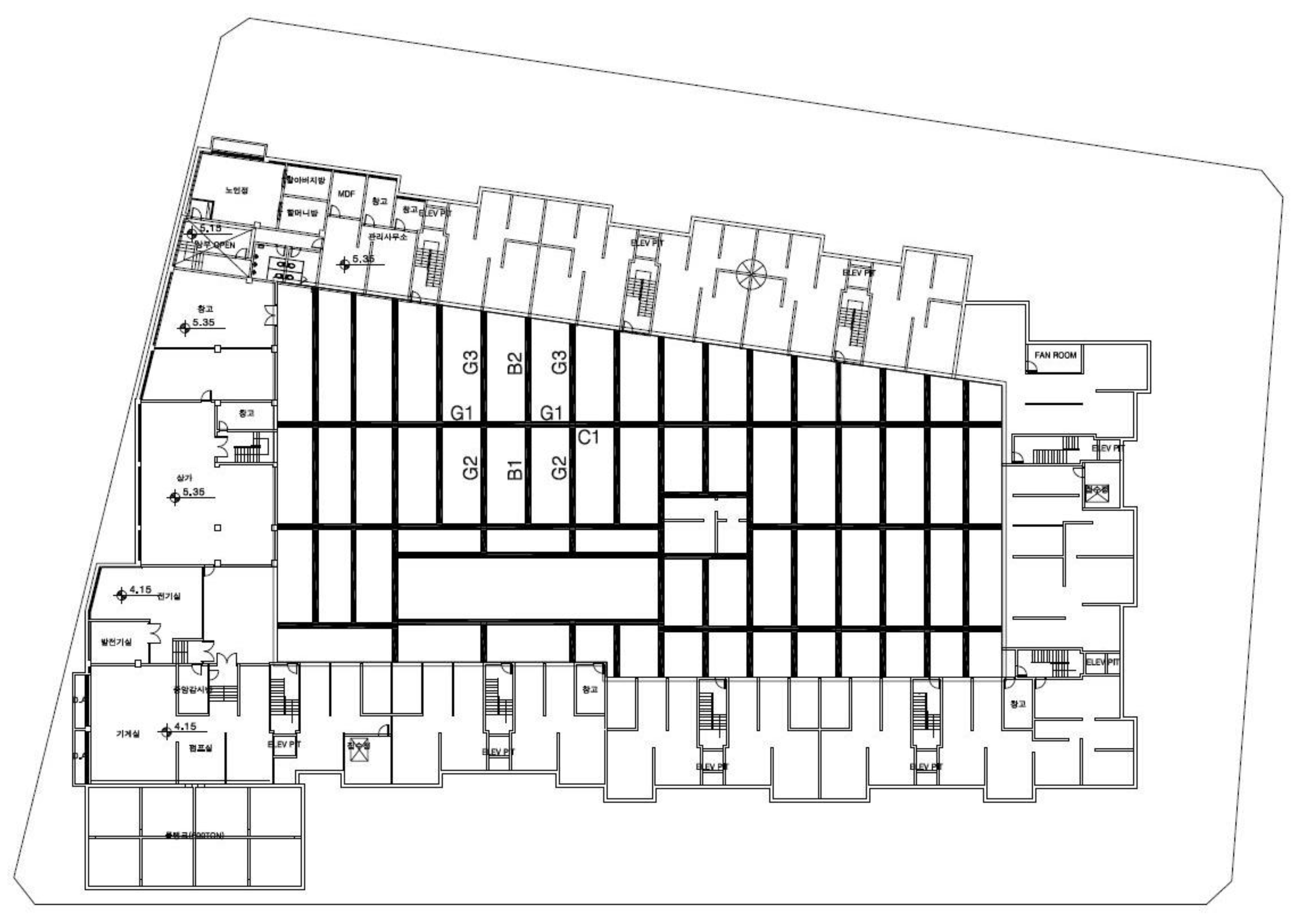
When the four methods are applied to expand underground spaces (from B1F to B3F) of an example case, the structural analysis results and the size of the required main structural members for each method are explained in this section. In consideration of the roles of temporary members and structural members after extending substructure, column and beam sizes were designed. By contrast, the sizes of strut and H-piles were designed based on the requirements of temporary members only. Figure 8 shows a structural plan for the B1F. Temporary struts were required to be installed at a depth of 2.5 m for cases applying the bottom-up method. On the other hand, because the structural frames of extended underground spaces, including beams and slabs, take the place of temporary struts, they are not considered for the structural analysis in these examples.

5.1. Bottom-Up Method

The structural system of substructure extended by the bottom-up method was the conventional RC frame system. Table 3 presents the sizes of main structural members and ratios of acting stress to the corresponding holding strengths of each member by force type. The highest values can be observed in the girders on the ground floor, where the ratio of force to holding strength reaches 0.992. These results indicate that the members are optimally designed. Column C1 (B5F) and strut ST7 have axial force ratios of 0.987 and 0.773 during construction, respectively. Therefore, it could be concluded that the designed structural members are safe for the applied load.

5.2. Normal Top-Down Method after Demolition

For the structural members of underground spaces extended by the normal top-down method after demolition, steel girders and steel-reinforced concrete columns were used. Table 4 lists the sizes of used structural members and the ratios of acting stress to their holding strengths. The ratios of the holding strengths of the girders reach 0.810 and 0.867 at G1 and G3, respectively. For the columns, the ratio reaches 0.357 at C3. The maximum ratios of the columns are smaller than those of other members because the top-down method requires steel reinforced concrete (SRC) columns that are composed of PRD-installed steel columns and concrete. Therefore, all examples that apply the normal top-down method after demolition are structurally stable and the structural members are designed optimally.

5.3. Normal Top-Down Method in Parallel with Demolition

The demolition process of existing substructures using the normal top-down method in parallel with demolition is different from that of the normal top-down method after demolition. However, the process for constructing structural frames of substructures extended by the normal top-down method in parallel with demolition is very similar to that by the normal top-down method after demolition. Therefore, the results of structural analyses for these two methods are similar.

5.4. Top-Down Method Using Double-Beam Systems

Table 5 shows the sizes and ratios of structural members in applying the top-down method using double-beam systems. Structurally, high strength ratios of 0.965 and 0.910 are observed at C1 in B5F and B4F, respectively. Because ratios of actual stress to holding strength of every structural member are less than 1.0, the examples applying the top-down method using double-beam systems are structurally stable.
As shown by the results of the structural analysis of substructures extended by the four methods, all of the examples were structurally stable.

6. Results and Analysis

The constructability issues in the four extension methods were analyzed and compared from the perspectives of construction cost and scheduling. The construction cost of each method was calculated based on actual quantities of materials and laborers. Construction scheduling was predicted using general construction durations from sites in South Korea based on a schedule planning method for top-down methods proposed by Lee et al. [22].

6.1. Scheduling Perspective

The vertical underground extension methods involve several types of work, including preparation, support installation, demolition and backfill work, retaining walls, pile work, PRDs, temporary post work, strut and excavation work, top-down and excavation work, foundation work, structural frame construction, finish work, inspection, and miscellaneous work. The detailed construction durations of each type of work were assessed by experts based on calculated quantities and productivities for each type of work, as shown in Table 6. To calculate the amount of excavated soil, the daily excavation workload and construction coefficient should be considered. In this paper, the daily excavation workload was assumed to be 300 m3 per day, which is consistent with the average daily excavation workload (300 to 400 m3) in Seoul, South Korea. The construction coefficients for the strut and top-down methods are 1.0 and 0.9, respectively.
Table 7 presents the predicted construction durations of each work for vertically expanding underground spaces using the four methods. From the scheduling perspective, the top-down method using double beams in parallel with demolition is the most efficient method for vertically expanding underground spaces of existing buildings. In addition, it is more efficient in the order of the top-down method in parallel with demolition, top-down method after demolition, and bottom-up method.
As the number of basement floors to be expanded increases, the differences among the total construction durations of each extension method generally increase. The increase rates of the construction durations for constructing structural frames of underground spaces using the bottom-up method are greater than those for performing finishing work using the top-down methods. Therefore, from the scheduling perspective, the greater the number of basement floors to be extended, the more advantageous the top-down method using double beams.
The total construction durations of the three top-down methods for extending existing underground spaces are approximately 9% to 25% shorter than those of the bottom-up method in the illustrative examples because the top-down methods do not include the construction duration required for installing structural frames of extended underground spaces. However, the differences among the total construction durations of the top-down methods and bottom-up method for vertically extending underground spaces are smaller than those related to installing structural frames for extended underground spaces because the top-down methods should additionally consider the construction duration of finishing work, unlike the bottom-up method.
Top-down methods in parallel with demolition processes are more effective than the top-down method after demolition from the scheduling perspective. Top-down methods in parallel with demolition should consider construction durations for installing supports for existing underground spaces, but they do not consider the construction duration for demolishing entire existing substructures and backfilling prior to installation of retaining walls, unlike the top-down method after demolition. In South Korea, the construction duration for support installation (20 working days) is generally shorter than that for demolition and backfilling work (40 days). If the top-down method using double beams in parallel with the demolition process is applied, we should also consider the construction duration for temporary post-work (13 days) but should not consider the construction duration for PRDs (31 days). Therefore, the top-down method using double beams might eliminate 18 working days.
The construction durations per extended basement floor of the four construction methods were also compared in this study (Figure 9). The construction duration per extended basement floor of the top-down method using double beams in parallel with demolition was generally the shortest, followed by the normal top-down method in parallel with demolition, top-down method after demolition, and bottom-up method. The construction duration per extended basement floor when applying the top-down method using double beams in parallel with demolition was approximately 75% to 78% of that of the bottom-up method. Interestingly, the decrease rate in construction duration per extended basement floor when applying the normal top-down method after demolition (35%) was slightly greater than those of the normal top-down methods in parallel with demolition and using double beams (34% and 32%, respectively).

6.2. Cost Perspective

The quantities and itemized unit costs for several types of work for each construction method were calculated by experts in South Korea based on the construction cost calculation ratio standards published by the PPS in South Korea. Table 8 lists the used construction cost calculation ratio standards. Material and labor costs, miscellaneous expenses, general administrative expenses, profits, and value-added tax (VAT) were considered in this study.
Table 9 lists the calculated total extension costs of the illustrative examples. From the cost perspective, the top-down method using double beams in parallel with demolition is the most efficient method for vertically expanding existing underground spaces. In addition, it is more economically advantageous in order of the normal top-down method after demolition, normal top-down method in parallel with demolition, and bottom-up method. In all examples, as the number of basement floors to be expanded increases, the differences among the total underground extension costs of each construction method generally increase. Therefore, the greater the number of basement floors to be extended, the lower the relative vertical underground extension cost of the top-down method using double beams.
The vertical underground extension costs of the top-down methods are approximately 7% to 9% lower than that of the bottom-up method because the construction costs of structural frames for vertically extending underground spaces and piling processes using the top-down methods are lower than those of the bottom-up method. However, the costs of top-down construction using steel frames should be considered when applying top-down methods to increase the number of floors in existing underground structures. Unlike the trends in the scheduling perspective, the normal top-down method after demolition is more effective than that in parallel with demolition from the cost perspective because the cost associated with supporting existing underground spaces during top-down construction processes ($172,000) is greater than the backfilling costs ($54,000) of the top-down method after demolition. The most economical method is the top-down method using double beams in parallel with the demolition process because this method might reduce the costs of PRDs, top-down construction, and structural frame construction simultaneously, unlike the other methods.
The extension costs per basement floor of the four methods were also compared in this study (Figure 10). The cost per extended floor for the top-down method using double beams in parallel with demolition is generally the lowest, followed by the top-down method after demolition, top-down method in parallel with demolition, and bottom-up method. The total extension cost per basement floor when applying the top-down method using double beams in parallel with demolition is approximately 90% of that of the bottom-up method. The decrease rates in the extension cost per basement floor of the four methods as the number of floors increases are similar at 18% to 19%.

7. Discussion and Conclusions

In this study, we analyzed the constructability of the four methods for vertically extending existing underground spaces of buildings, namely the bottom-up method, normal top-down method after demolition, normal top-down method in parallel with demolition, and top-down method using double beams in parallel with demolition. To analyze constructability of each method, their cost and scheduling perspectives were considered. The vertical underground extension costs and construction durations of 12 illustrative examples were calculated and compared in this study. Considering the number of basement floors extended vertically by the four methods, 12 illustrative examples were created. Their structural stabilities were also verified in advance.
Generally, the top-down methods were more effective than the bottom-up method from both the cost and scheduling perspectives. Among the four vertical underground extension methods, the top-down method using double beams was the most beneficial method. It was more beneficial in order of other top-down methods and the bottom-up method. From the financial perspective, the normal top-down method after demolition was more economical than that in parallel with demolition, whereas the opposite trend appeared from the scheduling perspective. Because the construction processes of the two top-down methods are different, different work types and workloads are required to apply different methods. Therefore, the cost savings of both methods differ from the time savings. The larger the number of basement floors to be expanded, the more financially and periodically beneficial the top-down method using double beams in parallel with demolition is in comparison to other methods. Interestingly, the benefits of schedule management for the top-down method using double beams are greater than those for the other methods.
Comparative analysis of the constructability issue of the vertical underground extension methods can help determine adequate methods to expand underground spaces without demolishing entire existing buildings and with efficient management of costs and schedules. Although examples were presented and analyzed from the two perspectives in this study based on calculated quantities, regulations, realistic assumptions, etc., our findings have not yet been applied to real-world projects. In South Korea, the government and private sector have selected pilot projects for applying vertical underground extension methods, such as large-scale residential complexes, to improve such environments and increase the number of parking lots in underground spaces. However, these projects have been delayed based on safety concerns and the absence of relevant regulations.
Furthermore, this paper focused on building systems in South Korea only. As the unit costs of construction materials, productivity indexes, and levels of construction technologies used vary across different countries, the impacts of the four vertical underground extension methods on time and cost reduction in other countries may differ from those in South Korea. Therefore, the methodology for calculating costs and scheduling of extending underground spaces can be applied to other countries with minor adjustments to such variables. However, we expect that the quantity of construction materials that would be used and dismantled for extending underground spaces without demolishing entire existing buildings would be similar, regardless of the aforementioned regional differences. Therefore, various vertical underground extension methods should be applied to real-world projects in other countries to calculate, validate, and verify their actual effects on construction costs and scheduling in the future.

Author Contributions

S.-Y.S. conceptualized this study, analyzed collected data, and drafted the article. B.L. collected and analyzed valid cost and schedule data and investigated structural stability of cases in this article. J.W. drafted and reviewed the manuscript. All authors have read and agreed to the published version of the manuscript.

Funding

This research was supported by a grant (20RERP-B099826-06) from Residential Environment Research Program (RERP) funded by Ministry of Land, Infrastructure and Transport of Korean government.

Institutional Review Board Statement

Not applicable.

Informed Consent Statement

Not applicable.

Data Availability Statement

Data available on request due to restrictions eg privacy or ethical.

Conflicts of Interest

The authors declare no conflict of interest.

Abbreviations

1FFirst floor
B1F to B5FBasement first floor to basement fifth floor
BFBasement floor
CColumn
CIPCast in place
GGirder
KRWKorean Won
PPSPublic Procurement Service
PRDsPercussion rotary drills
RCReinforced concrete
STStrut
USDUnited States Dollar
VATValue-added tax

References

  1. Furlan, R.; AL-Mohannadi, A. An Urban Regeneration Planning Scheme for the Souq Waqif Heritage Site of Doha. Sustainability 2020, 12, 7927. [Google Scholar] [CrossRef]
  2. Jung, S.J.; Kim, S.-K.; Seo, S.Y. Structural safety of the building constructed by top-down method corresponding to earth pressure distribution and floor system. J. Archit. Inst. Korea 2017, 33, 3–10. [Google Scholar]
  3. Volchko, Y.; Norrman, J.; Ericsson, L.O.; Nilsson, K.L.; Markstedt, A.; Öberg, M.; Mossmark, F.; Bobylev, N.; Tengborg, P. Subsurface planning: Towards a common understanding of the subsurface as a multifunctional resource. Land Use Policy 2020, 90, 104316. [Google Scholar] [CrossRef]
  4. Bobylev, N. Underground space as an urban indicator: Measuring use of sub- surface. Tunn. Undergr. Space Technol. 2016, 55, 40–51. [Google Scholar] [CrossRef] [Green Version]
  5. Bobylev, N. Comparative analysis of environmental impacts of selected underground construction technologies using analytic network process. Autom. Constr. 2011, 20, 1030–1040. [Google Scholar] [CrossRef]
  6. Kim, U.; Min, B.; Kang, M.; Kim, D.; Choi, H. Behavior Case Study of Temporary Structures during Underground Extension Work by Field Measurement. J. Korean Geo-Environ. Soc. 2020, 21, 5–13. [Google Scholar]
  7. Bobylev, N. Mainstreaming sustainable development into a city’s Master plan: A case of urban underground space use. Land Use Policy 2009, 26, 1128–1134. [Google Scholar] [CrossRef]
  8. Kim, K.M.; Rhim, H.C.; Lee, K.J. Development of underground space underneath existing buildings. In Proceeding of the 2010 Conference of Architectural Institute of Korea, Cheongju, Korea, 23 October 2010; pp. 153–154. [Google Scholar]
  9. Bing, C. Floating underground extension method—Remodeling case 2. Remodeling 2012, 46, 13–20. [Google Scholar]
  10. Jang, D.; Park, D.; Kim, Y.; Lim, H. Research on the development of FUSEM method for Seoul City main hall. In Proceedings of the Conference of Architectural Institute of Korea, Gwangju, Korea, 25 October 2012; pp. 513–514. [Google Scholar]
  11. Lee, J.; Bing, C. Remodeling case—Chungdam Chunggu Apartment. Build. Constr. 2012, 12, 42–51. [Google Scholar]
  12. Park, D.-S.; Lew, Y.-K.; Choi, K.; Lee, J. Introduction of floating underground space extension method (FUSEM) for preservation and continuous utilization of old Seoul city hall. Mag. Korea Concr. Inst. 2013, 25, 44–48. [Google Scholar]
  13. Kim, S.K.; Lee, J.E.; Kim, T.W.; Koo, J.M.; Jung, S.; Seo, S.Y. Construction technology and structural safety assessment for expansion of underground parking lot of apartment complex. In Proceedings of the 2016 Conference of Architectural Institute of Korea, Busan, Korea, 4–6 October 2016; pp. 1471–1472. [Google Scholar]
  14. Jung, S.J.; Kim, J.H.; Lee, B.H.; Hwang, K.S.; Seo, S.Y. Establishment of a technology for earthwork safety at new construction/extension of underground parking lot in building. In Proceedings of the 2018 Conference of Korea Concrete Institute, Changwon, Korea, 1 May 2018; pp. 797–798. [Google Scholar]
  15. Seo, S.y.; Lee, B.; Won, J. Comparative analysis of economic impacts of vertical extension methods for underground spaces of existing buildings. Sustainability 2020, 12, 975. [Google Scholar] [CrossRef] [Green Version]
  16. Ha, T.; Lee, S. Advanced construction stage analysis of high-rise building considering creep and shrinkage of concrete. In Proceedings of the 2013 World Congress on Advances in Structural Engineering and Mechanics (ASEM13), Jeju, Korea, 8–12 September 2013; pp. 2139–2147. [Google Scholar]
  17. Lee, D.; Kim, D.; Kang, P. Stories of Strong and Beautiful Building Construction (6); Baro Construction Key-Technology: Seoul, Korea, 2012. [Google Scholar]
  18. Thompson, J.; Zadoorian, C. A case study for top-down and construction methodology for a high-rise development in Los Angeles, California. In Proceedings of the SEAOC Convention Proceedings, Big Island, HI, USA, 23–27 September 2008; pp. 1–8. [Google Scholar]
  19. Ro, Y.-C.; Lee, C.-S. Selection of retaining wall system for underground parking lots expansion of apartments. J. Korea Inst. Constr. Eng. Manag. 2008, 9, 99–107. [Google Scholar]
  20. Archidata Design. Eart Retaining Wall. Available online: http://www.archidata.co.kr/NewWin/NewWin.asp?VT=Design&selID=54599&ddcodeid=2291 (accessed on 9 January 2020).
  21. Seo, S.; Lee, R.; Construction, S.H. Permanent earth retaining composite frames for constructing underground structure. In Proceedings of the Conference of Architecutal Institute of Korea, Jecheon, Korea, 24–25 October 2005; pp. 41–68. [Google Scholar]
  22. Lee, D.; Kim, D.; Kang, P. Sturdy and Beautiful Architecture Construction Story 5—Top-Down Method; Baro Construction Technology: Seoul, Korea, 2013. [Google Scholar]
Figure 1. Overall research process.
Sustainability 13 03647 g001
Figure 2. Selection process of vertical underground extension method without demolishing entire existing buildings.
Sustainability 13 03647 g002
Figure 3. Vertical underground extension process of the bottom-up method (basement first floor to basement third floor (B1F to B3F)). (a) Demolition of existing underground structures, (b) backfill and installation of retaining walls, (c) installation of H-piles and temporary struts, (d) construction of foundation, (e) elimination of struts and construction of structural frames (from B3 to B1), and (f) completion.
Sustainability 13 03647 g003
Figure 4. Vertical underground extension process of the top-down method after demolition (from B1F to B3F). (a) Demolition of existing underground structures, (b) backfill and installation of retaining walls, (c) excavation and construction of structural frames on B1F (1st stage), (d) excavation and construction of structural frames on basement second floor (B2F) (2nd stage), (e) completion of excavation and foundation construction, and (f) overall completion.
Sustainability 13 03647 g004
Figure 5. Vertical underground extension process of the top-down method in parallel with demolition (from B1F to B3F). (a) Support installation in the existing underground structure, (b) installation of retaining walls and percussion rotary drill (PRD) construction, (c) demolition of existing slabs, (d) construction of structural frames on the ground floor, (e) excavation and construction of slabs on the ground floor, and (f) construction of foundation and structural frames on the third basement floor (from B3F to B1F) and overall completion.
Sustainability 13 03647 g005
Figure 6. Vertical underground extension process of the normal top-down method using double beams (from B1F to B3F). (a) Installation of retaining walls and supports in the existing underground structure, (b) placement of temporary posts, (c) demolition of existing slabs on the first basement floor and installation of temporary girders supporting double beams, (d) construction of slabs on the ground floor, (e) excavation and construction of structural frames on B3F (from B3F to B1F), and (f) dismantling temporary supports and beams for completion.
Sustainability 13 03647 g006
Figure 7. Detailed construction process for the double-beam system. (a) Installation of temporary posts, (b) installation of temporary girders supporting double beams, (c) construction of double beams on the girders, (d) construction of slabs, (e) construction of RC columns, and (f) dismantling temporary supports and beams for completion.
Sustainability 13 03647 g007
Figure 8. Structural plan of B1F.
Sustainability 13 03647 g008
Figure 9. Construction duration per extended basement floor using the four construction methods in the 12 illustrative examples (days).
Sustainability 13 03647 g009
Figure 10. Construction cost per extended basement floor for the four methods in the 12 illustrative examples ((United States Dollar (USD) K).
Sustainability 13 03647 g010
Table 1. The number of parking spaces in the existing and remodeled underground spaces.
FloorSize of Parking Lot ModulesNumber of Parking Spaces
FloorTotalIncrease Rate
Existing underground spaceB1F5.5 × 5.2 m7575-
Remodeled underground spaceB3F7.8 × 9.0 m59177136%
B4F7.8 × 9.0 m59236215%
B5F7.8 × 9.0 m59295293%
Table 2. Basic information of the illustrative examples.
No.Number of Extended Basement FloorsVertical Underground
Extension Method
Structural Type
13Bottom-upRC
23Top-down after demolitionSteel
33Top-down in parallel with demolitionSteel
43Top-down using double-beam systemSteel
54Bottom-upRC
64Top-down after demolitionSteel
74Top-down in parallel with demolitionSteel
84Top-down using double-beam systemSteel
95Bottom-upRC
105Top-down after demolitionSteel
115Top-down in parallel with demolitionSteel
125Top-down using double-beam systemSteel
Table 3. Sizes and force ratios of structural members in the example applying the bottom-up method.
MemberSizeTypeForce Ratio of Acting Stress to Holding Strength
GirderG1 first floor (1F)700 × 900Moment0.908
Shear force0.992
G2 (1F)Moment0.781
Shear force0.566
G3 (1F)Moment0.700
Shear force0.961
G1 basement floor (BF)600 × 700Moment0.921
Shear force0.928
G2 (BF)Moment0.551
Shear force0.480
G3 (BF)Moment0.781
Shear force0.637
ColumnC1 (B3F)600 × 600Axial force0.888
C1 (B4F)700 × 700Axial force0.888
C1 (B5F)Axial force0.987
StrutST1H-300 × 300 × 10 × 15Axial force0.172
ST2H-300 × 300 × 10 × 15Axial force0.212
ST3H-300 × 300 × 10 × 15Axial force0.245
ST4H-300 × 300 × 10 × 15Axial force0.307
ST5H-300 × 300 × 10 × 15Axial force0.411
ST6H-300 × 300 × 10 × 15Axial force0.560
ST7H-300 × 300 × 10 × 15Axial force0.773
Table 4. Sizes and ratios of structural members in the example applying the normal top-down method after demolition.
MemberSizeForce Ratio of Acting Stress to Holding Strength
1FBF1FBF
GirderG1H-588 × 300 × 12 × 20H-500 × 200 × 10 × 160.7920.810
G2H-600 × 200 × 11 × 17H-466 × 199 × 8 × 120.7600.726
G3H-588 × 300 × 12 × 20H-500 × 200 × 10 × 160.8600.867
ColumnC1(B3F)700 × 700
(H-400 × 400 (B3F), H-414 × 405 (B4F-5F))
0.266
C2(B4F)0.267
C3(B5F)0.357
Table 5. Sizes and ratios of structural members in the example applying the top-down method using double-beam systems.
MemberSizeForce Ratio of Acting Stress to Holding Strength
GirderG1H-500 × 200 × 10 × 160.792
G2H-350 × 175 × 7 × 110.760
ColumnC1(B3F)600 × 6000.792
C2(B4F)0.910
C3(B5F)650 × 6500.965
Table 6. Calculated construction durations for each type of work in the illustrative examples.
Work TypeCalculated Construction Duration (Unit: Day)
Preparation20
Support installation20
Demolition and backfill40
Retaining wallEquipment preparation2
Cast in place (CIP) installation= # of CIPs/average daily workload= 419/10 = 41.9
Application of equipment2
Subtotal45.9
PilePile installation= # of piles/average daily workload= 72/10 = 7.2
PRDOut casing3
Equipment preparation3
PRD installation= # of PRDs/average daily workload= 25/1.1 = 22.7
Application of equipment2
Subtotal30.7
Temporary post work13
Foundation30
Structural frame construction90
Finish45
Inspection60
Miscellaneous30
Extended floors of underground spaces
B3FB4FB5F
Strut and excavationStrut= # of strut layers ×20 (days)
= 4 × 20 = 80= 5 × 20 = 100= 7 × 20 = 140
Excavation= Area of floors excavated in underground spaces × height of excavated underground spaces/(daily excavation workload × coefficient of construction (1.0))
= (1886.1 × 10.5)/(300 × 1.0) = 66.0= (1886.1 × 14.0)/(300 × 1.0) = 88.0= (1886.1 × 17.5)/(300 × 1.0) = 110.0
Subtotal80100140
Top-down and excavationTop-down= # of floors of extended underground spaces × 25 (days)
= 3 × 25 = 75= 4 × 25 = 100= 5 × 25 = 125
Excavation= Area of floors excavated in underground spaces × height of excavated underground spaces/(daily excavation workload × coefficient of construction (0.9))
= (1886.1 × 10.5)/(300 × 0.9) = 66.0= (1886.1 × 14.0)/(300 × 0.9) = 88.0= (1886.1 × 17.5)/(300 × 0.9) = 110.0
Subtotal75100125
Table 7. Predicted construction durations for the 12 illustrative examples by work type (unit: day).
Work TypeTo B3FTo B4FTo B5F
Extension MethodExtension MethodExtension Method
(A)(B)(C)(D)(A)(B)(C)(D)(A)(B)(C)(D)
Preparation202020202020202020202020
Support installation 2020 2020 2020
Demolition and backfill4040 4040 4040
Retaining wall424242424242424242424242
Pile 7 7 7
PRD 3131 3131 3131
Temporary post work 13 13 13
Strut and excavation80 100 140
Top-down and excavation 757575 100100100 125125125
Foundation303030303030303030303030
Structural frame construction90 120 150
Finishing 454545 606060 757575
Inspection6060606080808080100100100100
Miscellaneous303030303030303030303030
Total construction duration289263243225339303283265409343323305
Difference-(26)(46)(64)-(36)(56)(74)-(66)(86)(104)
Decrease rate-9.0%15.9%22.1%-10.6%16.5%21.8%-16.1%21.0%25.4%
(A) denotes the bottom-up method. (B) denotes the normal top-down method after demolition. (C) denotes the normal top-down method in parallel with demolition. (D) denotes the top-down method using double-beam systems.
Table 8. Construction cost calculation ratio standards provided by the PPS in South Korea.
No.ClassificationRatio
1Material costQuantities and itemized unit costs
2Direct labor costQuantities and itemized unit costs
3Indirect labor cost(2) × 7.30%
4Subtotal(2 + 3)
5Overhead costStatement
6Accident and employment insurance(4) × 3.75%
7Health insurance(2) × 3.23%
8Long-term care insurance(7) × 8.51%
9Annuity insurance and retirement deduction(2) × 6.80%
10Safety management expense(1 + 2) × 5.50%
11Expense for environmental conservation(1 + 2 + 5) × 0.05%
12Other expense(1 + 4) × 7.8%
13Subtotal(6 + 7 + 8 + 9 + 10 + 11 + 12)
14General administrative expense(1 + 4 + 5 + 13) × 5.5%
15Profit(4 + 5 + 13 + 14) × 12%
16Net construction cost(1 + 4 + 5 + 13 + 14 + 15)
17VAT(16) × 10%
18Total construction cost(16 + 17)
Table 9. Comparison of calculated underground extension costs by work type (unit: United States Dollar (USD) K; USD 1 = 1113.7 Korean Won (KRW)).
Work TypeTo B3FTo B4FTo B5F
Extension MethodExtension MethodExtension Method
(A)(B)(C)(D)(A)(B)(C)(D)(A)(B)(C)(D)
Support installation--172172--172172--172172
Demolition505505505505505505505505505505505505
Backfill5353--5353--5353--
Retaining wall201320132013201327042704270427043349334933493349
Pile110473073073014809789789781856122712271227
PRD-180180--240240--299299-
Temporary post---275---387---479
Strut290---363---508---
Excavation291229122912291240444044404440445176517651765176
Top-down (steel)-588588355-751751457-913913559
Structural frame construction268117761776176434382271227122554195276627662746
Total cost955887578877872612,58711,54511,66511,50215,64214,28814,40814,213
Difference-(801)(682)(832)-(1042)(922)(1085)-(1354)(1235)(1429)
Decrease rate-8.4%7.1%8.7%-8.3%7.3%8.6%-8.7%7.9%9.1%
(A) denotes the bottom-up method. (B) denotes the normal top-down method after demolition. (C) denotes the normal top-down method in parallel with demolition. (D) denotes the top-down method using double-beam systems.
Publisher’s Note: MDPI stays neutral with regard to jurisdictional claims in published maps and institutional affiliations.