Article

Optimization of the Opening Shape in Slot Spray Nozzles in a Field Boom Sprayer

by
Jacek Wawrzosek
1 and
Stanisław Parafiniuk
2,*
1
Department of Applied Mathematics and Computer Science, University of Life Sciences in Lublin, 20-612 Lublin, Poland
2
Department of Machinery Exploitation and Management of Production Processes, University of Life Sciences in Lublin, 20-612 Lublin, Poland
*
Author to whom correspondence should be addressed.
Sustainability 2021, 13(6), 3291; https://doi.org/10.3390/su13063291
Submission received: 11 February 2021 / Revised: 4 March 2021 / Accepted: 9 March 2021 / Published: 17 March 2021
(This article belongs to the Special Issue Sustainable Development of the Bioeconomy—Challenges and Dilemmas)

Abstract

:
The European Standard ISO 16122-2:2015 requires that the coefficient of variation for sprayed liquid fall should not exceed 10%. Field sprayers generate a stream of liquid sprayed at an angle that depends on the design of the nozzles. Among field boom sprayers, previous methods for selecting the shape of the opening of a single-slotted spray nozzle have been based on the following rectangular, triangular, normal, beta, and truncated normal distributions; distribution obtained from a nozzle with a stream in the form of an empty cone; and glued square functions. These methods, however, have provided a limited range of uniformity. Consequently, the initial assumption that the monotonicity of the function corresponds to the shape of a quarter of the symmetrical oval nozzle opening allows for a full computerized optimization of nozzle shape with a spray angle of α = 110° (or α = 120°). In this case, the spray uniformity parameter is controlled and freely declines almost to zero. In this study, based on the nonlinear shape obtained, we developed the shape of the nozzle outlet opening with a coefficient of variation of 0.388% using spline linear functions. Further applications of the symmetry of the developed model would allow for multiple modifications of the shape of this opening, and therefore, without changing the spray uniformity parameter, nozzles with slightly different characteristics could be obtained.

1. Introduction

1.1. Sustainable Development and Modern Agricultural Production

Farmers have always looked for ways to facilitate their daily work. A sprayer is used on both conventional and organic farms and is one of the devices that has contributed to dynamic developments in agriculture, horticulture, and fruit harvesting. Maintaining a rich agricultural landscape, low consumption of plant protection products, and well-functioning control systems are considered to be a good basis for the systematic, sustainable development of rural environments.
Chemical procedures implemented in agriculture still have far-reaching environmental, health, social, and economic consequences. Agricultural spraying presents a health risk for vulnerable groups, such as those living in rural areas and animals in the vicinity of sprayed fields, and for the general public. Therefore, the equipment and its use require constant control and improvement, as well as ongoing and improved knowledge and awareness by the entire society, especially those who do agricultural treatments. It is also important to ensure proper implementation of plant protection by introducing mandatory training for distributors of plant protection products and people who do treatments, as well as mandatory technical inspections of sprayers. It is very important to regulate the conditions of conducting integrated production and ecological agriculture [1].
The Sustainable Use of Pesticides Thematic Strategy, undertaken by the EU through the Sixth Community Environment Action Program, was aimed at minimizing the dangers and risks to human health and the environment resulting from the use of pesticides. The objectives are to improve the control of the use and distribution of pesticides, introduce safer active substances, and to encourage the use of low doses or pesticide-free crops [2].
The effectiveness of each agrochemical treatment is mainly the result of cultivation and soil conditions; purposefulness of treatments affecting soil, plants, or agrophages; preparation and equipment used; time and weather conditions; as well as the accuracy of treatment implementation. The accuracy of the treatment application is mostly the effect of the working pressure and speed of passage, which determine the size of the applied dose of the preparation. Each of these factors determines the effectiveness of field work. Sprayers have been designed and produced for families of various universal devices, for example, devices used for classic field cultivation, as well as specialized devices that are needed for fruit harvesting or rail maintenance. In order to improve the control of the spray application process, booms, blowers, and covers have been introduced for modifying the range and drift of the spray. Variability of the dosed preparation as well as the geometry of the nozzle or the dosing device arm are other modernization issues. An important design problem is the horizontal stabilization of a sprayer’s working boom so that its distance from the ground does not change due to vibrations resulting from the movement of the device on the ground [3].
Improvements to sprayers have mainly been focused on improving the design of the nozzles mounted in the sprayer device [4]. The design of the atomizer and its working parameters at a given pressure can affect the size of the spray angle, and thus also the uniformity of the sprayed liquid fall [5]. Over the years, studies have been conducted to improve the quality and uniformity of spraying liquids in order to achieve uniformity of coverage and homogeneity of the droplets obtained.
In the case of slot nozzles, it is important to maintain the assumed parameters and the shape of outlet openings during their operation. The quality of the nozzles and the materials used significantly affect the homogeneity of the droplets obtained. A homogeneous stream of sprayed liquid improves the spraying quality and reduces the drift of the liquid during the treatment [6].
The projected consequences of the implementation of the ideas for shaping new sprayer nozzle opening patterns, included in this study, are fully consistent with the concept of sustainable development, and include the following:
-
Improved uniformity and accuracy of chemical agricultural treatments;
-
Reduced consumption of agrochemicals;
-
Reduced agricultural treatment costs;
-
Improved agricultural and food product quality;
-
Maintenance of a better agricultural culture in agricultural areas;
-
Reduced pollution of soil, groundwater, reservoirs, water courses, and air.
The mathematical and operational research methods, used in this study, can be widely used for the production of nozzles with different spray angles and for different purposes.
The development of nozzle designs and the positioning of nozzles on a sprayer boom significantly affect the uniformity of the sprayed liquid falling onto the sprayed surface. The amount of nozzle wear influences the obtained coefficient of variation (CV) [7]. During periodic tests of agricultural sprayers, the value of this parameter determines the approval of the sprayer for use. The technical condition of the nozzles installed on a field sprayer boom also affects the quality of spraying and liquid application [8]. The size of the obtained droplets determines the degree of coverage, but also has an impact on the growing threats resulting from the phenomenon of liquid drift during the procedure. The drift phenomenon can be reduced by selecting appropriate spray parameters without reducing the quality of the treatment [9]. At present, in order to reduce the drift phenomenon, anti-drift and ejector nozzles are used, which produce air-entrained droplets that are less prone to drift [9,10,11,12]. In order to reduce the drift phenomenon, sometimes, structural solutions that use the phenomenon of electrostatic sprayers are used. These types of structures are most often used in orchard sprayers.

1.2. Spray Accuracy and Uniformity

Accurate and uniform spraying of plants mainly determines the effectiveness and quality of agricultural spraying, reduces the quantity of pesticides used in agricultural production, and contributes to environmental safety. The current standards for ground spraying units in field crops used for spraying the entire surface assume that 24 single-slotted nozzles are placed on the linear boom of a field sprayer, measuring 12 m in width, with 0.5 m spacing (Figure 1a). Notably, proper use of the stream of droplets exiting a group of cooperating slotted spray nozzles requires a more comprehensive knowledge of the stream formation produced by single-slotted spray nozzles [13]. The distribution of the quantity of atomized liquid from single-slotted spray nozzles is symmetrical and leptokurtic, which causes the distribution of the liquid quantity under the entire boom to lose uniformity. This has led to the development of new tools for modeling and predicting this process, as well as the design of enhanced slotted sprayers [7,13,14,15,16]. However, production processes do not ensure that even the best designed sprayers meet all parameters perfectly. Similarly, operation of a sprayer is accompanied by wear on sprayer nozzles. Hence, planning the appropriate position of each new or used sprayer nozzle on a field sprayer boom has proven to be a legitimate undertaking [17,18]. Only the combined process of both the design and manufacture of nozzles and modification of their position on the boom can significantly improve the quality of agricultural spraying and its costs for the farmer and the environment.
An important element of a precise fertilization system for liquid fertilizers and plant protection fertilizers is stable operation of the sprayer boom, which should be positioned parallel to the sprayed surface, without significant transverse fluctuations; this is especially important in the case of sprayers with large working widths [3,12].

2. Materials and Methods

2.1. Methodology of Designing the Shape of a Slotted Sprayer Nozzle Opening

The opening of a slot spray nozzle is a narrow, heterogeneous, almost elliptical slot which produces a single stream with cross-sections the shape of an almost ellipse, as shown in Figure 1b. This oval shape of a single flat stream observed on a dry measuring table at a distance of 0.5 m from the nozzle outlet is mainly due to (1) the designed spray angle α, (2) the opening shape of the slotted sprayer nozzle, and (3) the size of the opening. Hence, all three characteristics affect both the distribution of the liquid flow measured on the measuring table (Figure 2) along the entire length of the larger elliptical axis of a single jet and also the distribution of the liquid flow measured along the entire length of the sprayer boom (Figure 1c). Conversely, the requirement for a uniform spray distribution from the entire sprayer boom fitted with 24 slotted sprayer nozzles with a given spray angle α affects the requirement of the output distribution from a single-slotted spray nozzle and the resulting shape of the nozzle opening and its dimensions. Therefore, for the chosen working pressure and the set spray angle, the shape and dimensions of a small nozzle opening should proportionally correspond to the desired optimal distribution of the flow rate from a single nozzle.
For any given spray angle α, let the function f(x,α) of the argument x correspond to the output from the field sprayer boom at the point x within the range of the entire liquid stream at a distance of 0.5 m below the boom (Figure 1c). Let the point x = 0 coincide with the left end of the spray boom where the first nozzle is installed. Then, for any determined spray angle α, the design task is to find the optimal function f (x,α) of the argument x, which minimizes the functional called the liquid fall unevenness indicator calculated according to the dependency as follows:
η ( f ( x , α ) ) = 1 b a a b ( f ( x , α ) f ś r ( α ) ) 2 d x f a v g . ( α ) 100 %
where η ( f ( x , α ) ) is the liquid fall unevenness indicator dependent on the function f, a = 0.5 (m) is the beginning liquid output measurement at the beginning of a 12 m field sprayer boom, b = 11 (m) is the end liquid output measurement at the end of a 12 m field sprayer boom.
f a v g ( α ) is the arithmetic mean of the liquid output from the field sprayer boom within the area between a and b calculated according to Formula (2) as follows:
f a v g ( α ) = 1 b a a b f ( x , α ) d x
Note that η ( f ( x , α ) ) is the coefficient of variation (CV) known from the probability theory.

2.2. Previous Models of Liquid Flow from a Single Nozzle

Previous attempts to optimize the form of the function f (x,α) of the distribution obtained by the linear boom of a field sprayer have been carried out on the basis of individual nozzle inserts. Therefore, for any determined α, the solution is to select the theoretical distribution p(x,α) of the output from individual nozzles. So far, in order to model single nozzles, the following have been used: rectangular or triangular distribution [4,16,19], normal distribution or beta distribution [7,14], distribution in the form of double truncated normal distribution [15], or distribution obtained from a nozzle with a stream in the form of an empty cone [14,16]. Another model is the so-called average distribution model [20]. However, none of the mentioned models have generated results adequate for the actual data. Hence, it was proposed that the distribution in the form of symmetric spline function from polynomials of p and q degree be used to model single nozzles [13]. For p = q = 2, the parameters of this distribution are indicated there, allowing one to obtain the coefficient of variation of the entire boom at the level of 2.16% for a measuring table equipped with 0.05 m wide grooves (Figure 2), which corresponds to the coefficient of variation of the entire boom at the level of 1.85% for the measuring table equipped with 0.1 m wide grooves. This is a significant design step with regard to the ISO 16122-2:2015 standard [21] which requires that the coefficient of variation of the entire boom for a measuring table with 0.1 m wide grooves should not exceed 10%. These results silently ignore the known fact that the amount of liquid applied per unit area of cultivation depends on the working pressure, the speed at which the sprayer is moving, and the type of spray liquid. This means that these factors can usually be neglected when considering the shape of the nozzle opening.

2.3. The Proposed Method of Modelling the Output from the Single Nozzle

In the study, it is noted that resigning from the abovementioned significant limitations of mathematical nature imposed in the form of the target distribution of single nozzles allows for the introduction of innovative more optimal distributions, which lead to such nozzle improvement that it is theoretically possible to obtain even a zero value (!!) for the liquid fall unevenness indicator (1) expressed as the coefficient of variation (CV) for the entire boom.
It is also noted that (i) the size and (ii) the shape of the outlet opening, including (iii) the spray angle α, as the vertical angle of the stream of droplets, corresponds directly to the distribution p(x,α) of the output from single nozzles at a vertical distance of 0.5 m from the boom. Therefore, the optimal size and shape of the nozzle outlet opening should depend on the spray angle α and reflect the optimal distribution p ( x , α ) of the single nozzle output at a vertical distance of 0.5 m from the boom. Hence, for the selected (i) output of a single nozzle and (ii) its spray angle α, the optimization being carried out on the expression (1) for the entire boom comes down to selecting a distribution g 1 ( x , α ) of a single nozzle so that the distribution f (x,α) is a constant function within the range of 0.5 m from both ends of a 12 m field sprayer boom.
This strict requirement involves a computer search of an ambiguous nonlinear function g 1 ( x , α ) corresponding to the shape of a single nozzle opening and requires very precise manufacturing of durable nozzles, which is not always feasible for every technology.
In order to support maintaining a high standard of requirements for manufacturing nozzles when approaching the optimization of the expression (1) the function g 1 ( x , α ) is selected already in the form of a symmetrical piecewise linear function, the right arm of which is a non-increasing function, zeroing out beyond the range of the nozzle (2z) at a vertical distance of 0.5 m from the boom.

2.4. Procedures and Functions Used

Due to the adopted form of the liquid fall unevenness indicator (1), the nonlinear programming procedure is adopted as the optimization method. Here, we have assumed that at a vertical distance of h 0 = 0.5   m from the boom, the longer range of a single nozzle covers a range z 0 ;   z 0 . In order to minimize the functional η ( f ( x , α ) ) by computer, first the segment ( 0 , z 0 should be discretized. For example, for the spray angle α = 110 ° , where z 0 = h 0 t g ( α 2 ) 0.714   m with an accuracy of 0.01 m for i = 1 , , 72 , N = 72 , decision variables k i —the size of the output of a single nozzle per 1 cm section ( i 1 ; i at a vertical distance of 0.5 m from the boom are obtained. Furthermore, for the preselected K —nozzle output (ml) per 1 cm section ( 0 ; 1 within 1 min (achievable at the appropriate working pressure), simple linear limitations: k 1 = K and k i 1 k i 0 for i = 1 , , 72 , and moreover, the boundary conditions k i 0 for i = 1 , , 72 should be adopted. For such introduced discretization, it is best to use a spreadsheet as follows:
(1) To carry out the appropriate symmetrization of the output for the entire single nozzle;
(2) To add up, sequentially, overlapping output k i of nozzles located every 0.5 m [22].
This produces a step function f ( j ,   α ) for discrete arguments j = 1 , , 240 that expresses the amount of the entire output of the 12 m boom observed over 240 (or 120) sections corresponding to 0.05 m wide grooves (or 0.1 m, respectively). In turn, this allows the integrals in Formulas (1) and (2) to be converted into finite sums for the step function f ( j ,   α ) , in which addition includes only indexes j = 11 , , 230 (or j = 6 , , 115 , respectively). Therefore, the nonlinear objective function η ( f ( j , α ) ) obtained, together with the abovementioned linear constraints and boundary conditions, creates a nonlinear optimization model with N decision variables. Minimization of such a limited objective function (or its zeroing) can be performed, for example, using the Solver plugin, which is a product of Frontline Systems, Inc. [22] working with an Excel spreadsheet. Then, the precision of calculations requires taking into account the 7° angle, indicated in Figure 1b, at which all nozzles are installed:
g ( x , α ) = { k c e i l ( x ) / cos 7 for     x ( 0 ;   z 0 k 1 / cos 7 for       x = 0 ,
where c e i l ( x ) = min { k Ζ :   k x } is rounding up x to an integer.
For
g 1 ( x , α ) = { g ( x , α ) for   x z 0 ;   0 ) g ( x , α ) for   x 0 ; z 0 0 for   the   remaining   x
and for the total output of a single nozzle:
p ( α ) = z 0 z 0 g 1 ( x , α ) d x
p ( α ) is the distribution of the normalized symmetric probability density function:
p ( x ,   α ) = g 1 ( x , α ) / p ( α )     for   any   x
that is, the distribution of the amount of liquid under a single nozzle at point x at a distance h from the nozzle. It arises as a marginal distribution from the two-dimensional probability density function:
p ( x ; y ; α ) = { 1 / p ( α ) 0     for     ( x ; y ) { ( x ; y ) : z 0 x z 0 ;   0.5 g 1 ( x ; α ) y 0.5 g 1 ( x ; α ) } for   the   remaining   ( x ; y )
expressing the random position of droplets emerging in a homogeneous stream of atomized liquid sprayed from a single nozzle of optimal shape at the point (x, y) at a distance h 0 = 0.5   m from the nozzle. Thus, the three coordinates ( x ; y ; h )   for   x z ; z ,   y h h 0 0.5 g 1 ( x h 0 h ,   α ) ; + h h 0 0.5 g 1 ( x h 0 h ,   α )   ,   h > 0   and   z = h t g ( α 2 ) effectively reflect three components of the random position of the droplets emanating in a homogeneous stream of atomized liquid sprayed from one nozzle with an optimal shape fall. By homogeneity, in this study, we understand the identity of the probability at every point (x, y, h) at a given height h. There is a connection with the previously obtained, not very accurate, results presented in the form of the spray distribution density function, as a symmetrical curve with a bell-like shape corresponding to one of the typical only one-dimensional distributions, for example, the normal distribution [7,14].

3. Results

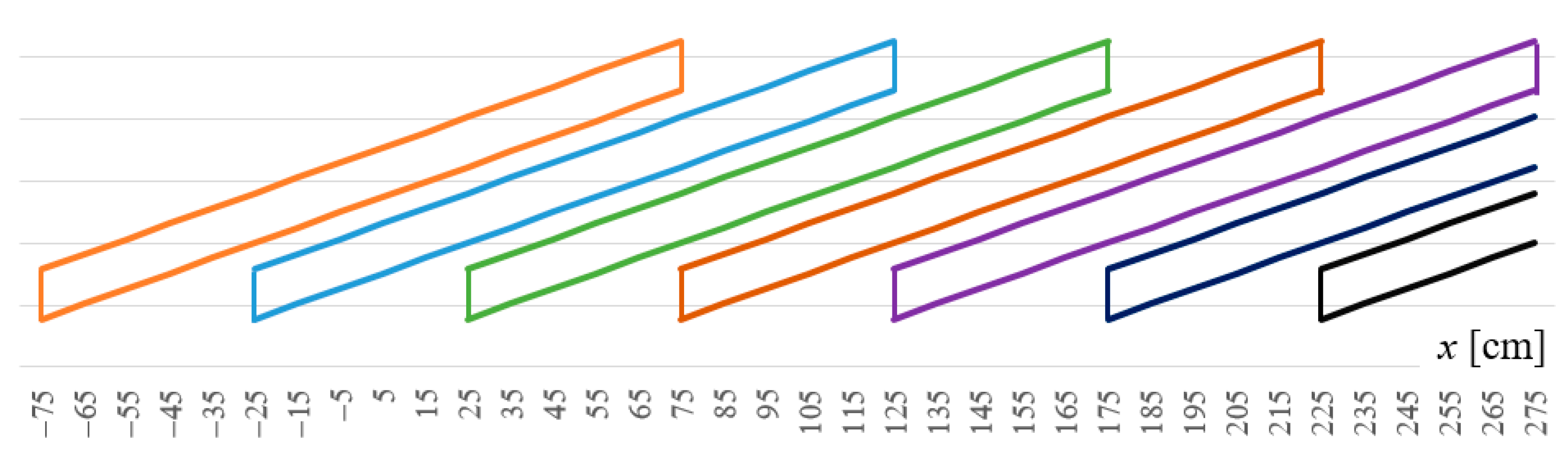
3.1. The Optimal Shape of the Nozzle Outlet for α = 110 ° and α = 120 °

The technology of making nozzles requires only a proportional transfer of the shape of the function g(x,α) to the shape G ( x , α ) of the outlet for a single nozzle. Hence, for any determined spray angle α, the shape of a single nozzle stream at a vertical distance of h 0 = 0.5   m from the boom is described by the curve as follows:
G ( x , α ) = ± 0.5 g 1 ( x , α )   for   any   x z 0 ; z 0
When C V = η ( f ( x , α ) ) = 0 , for α = 110 ° in Figure 3 (respectively, for α = 120 ° in Figure 4) the desired optimal cross-sectional shape G ( x , α ) of a homogeneous stream emerging from a single nozzle is shown at a vertical distance of h 0 = 0.5   m from the nozzle of the sprayer with a selected capacity K = 10   ( mL / ( min · cm ) ) .

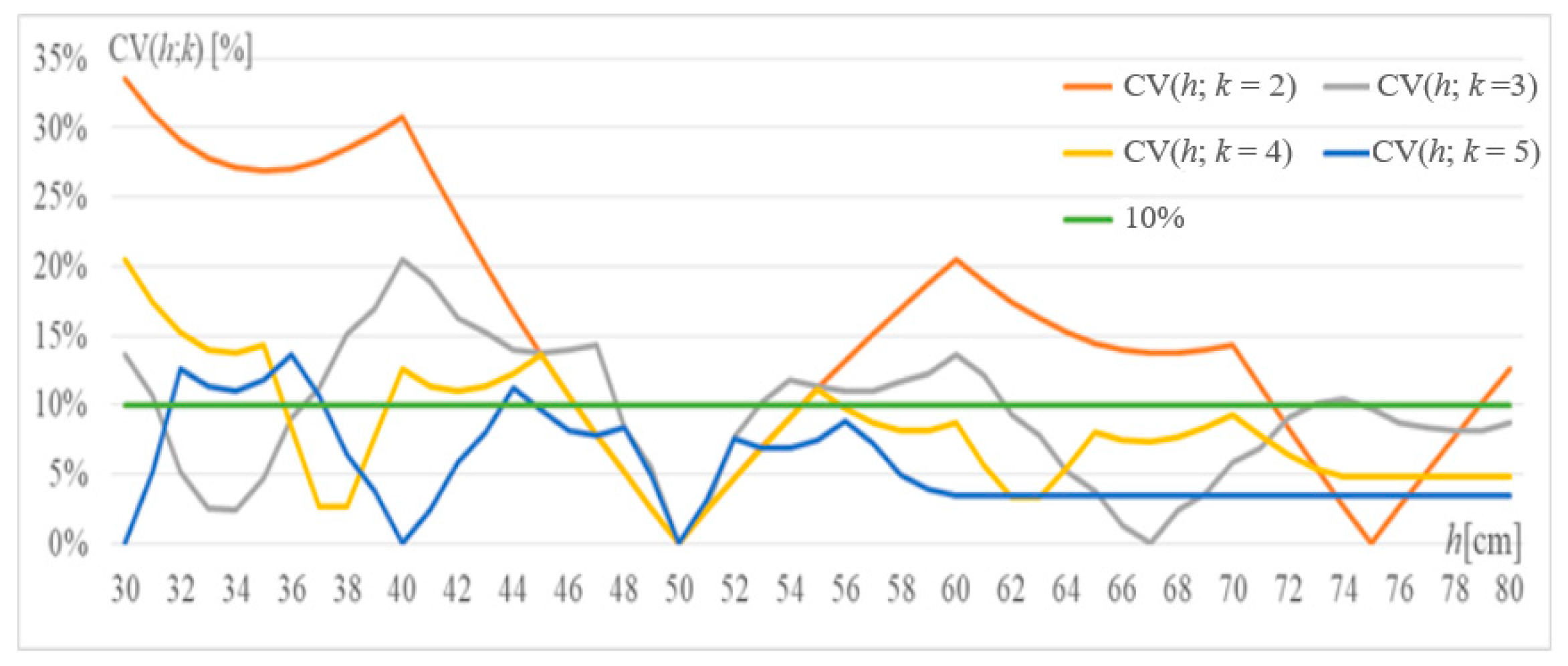
3.2. Accuracy and Uniformity of Spraying with Designed Nozzles

The amount of spray with the designed nozzles does not depend on the distance from the boom but does depend on the spray angle (Figure 5).
The coefficient of variation CV (h,α) of the efficiency on 10 cm sections of the designed sprayer boom in 1 min is a function of the distance h from the sprayer boom and the spray angle α (Figure 6). For a distance from 30 to 85 cm, the CV is less than 11.3%, and for a distance of 50 cm, it perfectly meets the ISO standard for 50 cm [21].
Together, this means that the efficiency of the sprayer boom equipped with such proposed nozzles is highly insensitive to transverse vibrations resulting from the sprayer’s movement over uneven terrain. It also means that changing the distance to the spray boom equipped with these nozzles can only slightly affect the quality of the spray.

3.3. Alternative Suboptimal Shape of the Nozzle Opening α = 110 °

It turns out that for any determined K and spray angle α, it is possible to select a symmetrical piecewise linear function g(x,α) of the argument x, which approaches the optimal solution expressed by the zeroing of the indicator (1) of liquid fall unevenness to a record-breaking degree. However, without breaking another theoretical record, and limiting ourselves to the simplicity of nozzle manufacturing and its limited commercial offer for particular spray angles α corresponding to classically produced, for example, 60°, 90°, 100°, 110°, and 120°, it is sufficient to indicate for these several fixed angles, such a symmetrical linear functions g(x,α) of the argument x with few breakpoints (i.e., with few points (x, g(x,α)) for changing the angles of inclination of particular function segments g(x,α)). The fewer breakpoints, the greater the simplicity of nozzle manufacturing, but also greater deviation from 0 in CV, i.e., for (1). But for just a few breakpoints, very satisfactory results can be obtained, allowing for a record-breaking approximation to zero for the liquid fall unevenness indicator (1).
An example of the implementation of such a curve in the form of a piecewise linear function for the spray angle α = 110 ° is presented in Figure 7.

3.4. Results for a Measuring Table with 0.1 m Wide Grooves

Therefore, for example, for α = 110 ° :
  • For the optimal shape of the cross-section of a single nozzle stream from Figure 3 and for a measuring table equipped with 0.1 m wide grooves, it was possible to obtain a coefficient of variation for the entire boom amounting to 1.27 × 10⁻⁴%.
  • For the suboptimal shape of the cross-section of a single nozzle stream from Figure 7 (i.e., for a much simpler implementation, a coefficient of variation amounting to 0.388% was obtained.
In the conducted implementations where the ISO 16122-2:2015 standard [21] was applied, it was possible to achieve 5 to 14.5 thousand-fold improvement over the result achieved by Kluza et al. [13].
The obtained shape brings the achieved solution closer to the geometric problem of arranging puzzles, paving stones, or tiles such that the sum of their widths is constant [23,24,25,26,27]. Consequently, further use of the symmetry of the developed nozzle opening model allows for multiple modifications of the shape of this opening, and therefore without changing the spray uniformity parameter, nozzles with slightly different characteristics can be obtained.
For example, in this way, we noticed 15 interesting two-dimensional modifications, unpublished here, of each of the three shapes A, B, and C, with one-dimensional marginal distributions measured along a boom equal to the nozzle efficiency distributions, respectively, of A, B and C types.

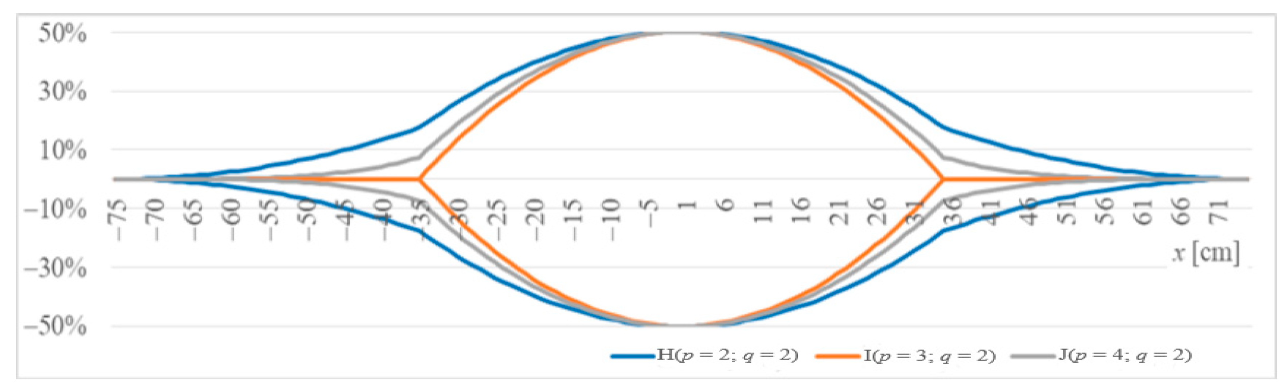
3.5. Optimum Spray Angles from Nozzles with a Parallelogram-Shaped Slot

In order to obtain a total homogeneous stream at a distance of h = 0.5 m from the boom, it is necessary to make the insert of each nozzle identical over its entire range z ;   z measured along the boom. This means that the narrow slit of the nozzle, usually at an angle of 7° to the boom, should be in the form of a parallelogram with angles of 90 ° 7 ° = 83 °   and   90 ° + 7 ° = 97 ° (Figure 8). Moreover, for the number of summed homogeneous contributions of k nozzles at a distance of h = 0.5 m from the boom over the entire length to be measured to be the same, the equality 2 z = k 0.5       for     k { 2 ; 3 ; 4 ; 5 } , where z = h t g ( α 2 ) must be held. Hence α = 2 a r c t g { k / 2 }   for   k { 2 ; 3 ; 4 ; 5 } . This means that for each of the four types of nozzles with spray angles measured along the boom axis a of 90°, 112.62°, 126.87°, and 136.40°, respectively, at a distance h = 0.5 m from the boom, coming from the efficiency of successive identical nozzles, the probability density functions for uniform distributions on intervals of 1, 1.5, 2, and 2.5 m, respectively, are shifted in relation to each other like nozzles, i.e., every multiple of 0.5 m, which allows them to be added like rectangular bricks obtaining, ignoring the ends of the boom, a long “rectangular wall” (Table 1). Only for k = 5, the range of CV determination should be additionally shortened by 0.5 m on each side. Then, CV = 0 for each of the four above-mentioned. spray angles.
The coefficient of variation CV(h, k) of efficiency on 10 cm boom sections as a function of distance h from the designed parallelogram nozzles D, E, F and G of the sprayer is usually greater than the CV (h, 110°) and CV (h, 120°) of both nozzles A and B (Figure 6 and Figure 9).

3.6. Nozzle Slot Shapes Created by Gluing Polynomials

After adjusting the methodology of Kluza et al. [13] to the above determinations, we obtain two polynomials with vertices for x = 0 and x = 75 glued at an arbitrarily selected point x = 35, which leads to the operation of the function:
g 2 ( x ,   α ) = { b x q + c for x 0 ; 35 ) a ( x 75 ) p for x 35 ; 75
with parameters a , c > 0 , b < 0 , where p , q 2 are natural numbers for the condition b 35 q + c = a ( 35 75 ) p . Hence, the further operation of e.g., the function:
g 3 ( x , α ) = g 2 ( x , α ) / cos 7     for     x 0 ; 75
and transformations, as in Section 2.4 and Section 3.1, allow us to obtain three suboptimal shapes of the nozzle slots (Figure 10) for the model parameters (9) included in Table 2.
Note that the suboptimal H nozzle with CV (h = 50 cm) = 1.58% slightly improves the already optimized result of Kluza et al. [13] by about 0.5%. This difference may result from the separateness of the optimization tools used and the nonlinearity of the objective function.

4. Discussion

The spraying process is used in various areas of economy, for example, fuel spraying, sprinklers with a fixed spray plate, air spraying, or irrigation systems [13]. In the operation of agricultural sprayers, slot nozzles are most often used in field sprayers, and specialized designs are used in orchard sprayers. Slot nozzles were initially made of metal, but their durability was not satisfactory. With the possibility of making nozzles from plastics, rapid development of new nozzle structures has been observed. The aim of ongoing work is to improve the effectiveness of the crop spraying procedure by achieving homogeneity and improvement of the desired spectrum of produced droplets related to the drift of the sprayed liquid as a result of air movement [9,10,11,12]. In the design of nozzles, the determining parameter is a specific output at the assumed pressure and the spray angle, which may change depending on the working pressure of the liquid. Changing the spray angle may change the uniformity of the spray distribution. The ISO standard for testing of agricultural sprayers in operation states that the CV cannot exceed 10% [21]. Therefore, a change in working parameters may disqualify the sprayer from use. However, a change in working pressure often results from the nature of the procedure being performed. A 50% change in the working pressure value results in a 50% reduction in the number of droplets with a diameter below 100 micrometers [10]. In order to limit the drift of the liquid, calibrated orifices mounted in nozzles have been introduced, which reduce the pressure of the liquid reaching the outlet nozzle. It has been shown that for the same working pressure, the number of drops below 150 micrometers can be reduced by over 80% [11].
In recent years, a dynamic development of ejector slot nozzles has been observed, which are available in various versions. Nozzles with this design produce large air-entrained droplets. Due to the greater mass of these droplets, they more easily penetrate the sprayed fields or the crowns of trees and shrubs. At the ends of the sprayer booms, nozzles can be used that create an asymmetrical stream of liquid that clearly cuts off the sprayed area from the unsprayed area. This is of particular importance when the procedure is performed in the vicinity of sensitive zones [27]. In the construction of slot nozzles, the shape of the slot in most cases is a spherical segment of a sphere and it is close to an ellipse. So far, only the existing theoretical distributions typical of probabilistic methods have been used to model individual nozzles, such as rectangular distribution, triangular distribution [4,16,19], normal or beta distribution [7,14] or in the form of a double-truncated normal distribution [15], or a distribution in the form of a symmetric spline of polynomials [13]. Despite the significant progress in construction results, especially in the last of the cited works, the permissible deviation from the production standard of such nozzles means that new nozzles have a small margin of error, which quickly disappears as a result of ordinary operation of sprayers.; therefore, there is a need for further improvement of slot sprayer nozzles.
Currently the proposed designs for the optimal shape of the nozzle opening of the field sprayer obtain good uniformity with even distribution of the liquid and help to meet the requirements necessary to obtain a positive certificate of the field sprayer [21,28,29,30,31]. This extends the service life of the most sensitive, wearing parts of the sprayers. Moreover, the obtained positive effect of the shape of the slot sprayer opening is valid for various spray angles and over a large range of the distance between the sprayer boom and the ground.
In this study, the model assumes that the operating pressure applied in the sprayer shortens the time of the sprayed liquid fall from height h so that the gravitational acceleration accompanying the rainfall only slightly distorts the straightness of the rainfall cone (Figure 1).
On the basis of Figure 6, it can be seen that the CV parameter for optimal nozzles type A and B is rather insensitive to transverse vibrations of the sprayer boom. Figure 9 shows that this parameter is more sensitive to transverse vibration of the boom for parallelogram nozzles D–G than for A and B nozzles. It is especially visible for types D and E. Figure 11 shows that nozzles I–J designed using glued polynomials are more sensitive to these vibrations than nozzles H.
Figure 12 and Figure 13 summarize the above studies by showing the distribution of the amount of liquid over 10 cm sections located 0.5 m below the sprayer boom using one of the nozzle types designed here. Figure 12 shows the uniform distribution of the amount of liquid using one of the optimal types, and Figure 13 shows the differentiation of the liquid fall for suboptimal types.

5. Conclusions

The processes of designing and manufacturing nozzles as well as modifying their position on the boom can significantly affect the quality of agricultural spraying and reduce the quantity of pesticides used in agricultural production, as well as affect environmental safety.
A virtual simulation of the field boom was carried out, illustrating the operation of the sprayer, together with an analysis of spraying uniformity for various spray angles and different distances from the measuring table. The extension of the virtual sprayer boom can be unlimited as you can add any number of nozzles on it. Thus, the obtained optimal nozzles can successfully work on longer booms.
Depending on the selected fixed spray angle, the optimal shapes of a single nozzle stream cross-section can be expressed by the nonlinear functions. It ensures the zero value of the coefficient of variation (CV).
The technological requirement of simplifying nozzle manufacturing allows for determining the shape of a single-slotted spray nozzle opening by means of a piecewise linear function, so that the uniformity parameter (CV) for the whole boom will not differ significantly from the ideal zero value.
For sample spray angles, three computer-developed shapes of the nozzle opening are presented, i.e., two optimal and one suboptimal. The optimal ones relate to the selected maximum K value of the output of a single nozzle, and the suboptimal one indicates the aspect ratio for each individual unit of the K value of the maximum output.
The presented optimization methods allow for their widespread use for the production of nozzles with different spray angles, different K parameters, and for different purposes, including various positions.
The efficiency of a sprayer boom equipped with the proposed nozzles is highly insensitive to transverse vibrations resulting from the sprayer’s movement on uneven terrain. This means that changing the distance to a sprayer boom equipped with these nozzles would only slightly affect the spray quality. Despite the existence of natural processes of corrosion, erosion, adhesion, and fouling, as well as clogging or accidental damage, it is precisely the equipment of slot sprayers with nozzles of such designed shapes that should result in their efficiency controlled by the classic ISO standard for a long time. This will contribute to extending the life of the nozzles with a very positive effect on the environment.

Author Contributions

Conceptualization, J.W. and S.P.; methodology, J.W.; software, J.W.; validation, J.W. and S.P.; formal analysis, J.W.; investigation, J.W. and S.P.; resources, J.W. and S.P.; data curation, J.W.; writing—original draft preparation, J.W. and S.P.; writing—review and editing, J.W. and S.P.; visualization, J.W. and S.P.; supervision, J.W. and S.P.; project administration, S.P.; funding acquisition, J.W. and S.P. All authors have read and agreed to the published version of the manuscript.

Funding

This research was funded by funded from the ‘Excellent science’ program of the Ministry of Education and Science as a part of the contract no. DNK/SP/465641/2020 “The role of the agricultural engineering and environmental engineering in the sustainable agriculture development”.

Institutional Review Board Statement

Not applicable.

Informed Consent Statement

Not applicable.

Data Availability Statement

Not applicable.

Conflicts of Interest

The authors declare no conflict of interest.

References

  1. Pruszyński, S.; Skrzypczak, G. Plant protection in sustainable agriculture. Fragm. Agron. 2007, 4, 127–139. [Google Scholar]
  2. Pruszyński, S.; Pruszyński, G. Sustainable use of pesticides. In Zagadnienia Doradztwa Rolniczego; 2013; pp. 23–39. Available online: https://www.cdr.gov.pl/pol/zdr/ZDR_2_2013.pdf (accessed on 16 March 2021).
  3. Lodwik, D.; Pietrzyk, J. Automated test station for transverse spray non-uniformity. J. Res. Appl. Agric. Eng. 2013, 59, 103–106. [Google Scholar]
  4. Orzechowski, Z.; Prywer, J. Wytwarzanie i Zastosowanie Rozpylonej Cieczy; PWN: Warsaw, Poland, 2018. [Google Scholar]
  5. Nowakowski, T.; Chlebowski, J. The impact of liquid pressure and design of fan atomizers on spraying angle. Agric. Eng. 2008, 1, 319–323. [Google Scholar]
  6. Butler Ellis, M.C.; Swan, T.; Miller, P.C.H.; Waddelow, S.; Bradley, A.; Tuck, C.R. PM—Power and Machinery: Design factors affecting spray characteristics and drift performance of air induction nozzles. Biosyst. Eng. 2002, 82, 289–296. [Google Scholar] [CrossRef]
  7. Mawer, C.J.; Miller, P.C.H. Effect of roll angle and nozzle spray pattern on the uniformity of spray volume distribution below a boom. Crop Prot. 1989, 8, 217–222. [Google Scholar] [CrossRef]
  8. Declercq, J.; Huyghebaert, B.; Nuyttens, D. An overview of the defects on test field sprayers in Belgium. In Proceedings of the 3rd European Workshop on Standardised Procedure for the Inspection of Sprayers in Europe—SPISE 3, Brno, Czech Republic, 22–24 September 2009; Volume 3, pp. 157–163, ISBN 978-3-930037-66-7. [Google Scholar]
  9. Nuyttens, D.; Baetens, K.; De Schampheleire, M.; Sonck, B. Effect of nozzle type, size and pressure on spray droplet characteristic. Biosyst. Eng. 2007, 97, 333–345. [Google Scholar] [CrossRef]
  10. Ozkan, H.E. Reducing Spray Drift; Ohio State University Extension Service, Publication AEX: Columbus, OH, USA, 2000; pp. 816–900. [Google Scholar]
  11. Ozkan, H.E.; Derksen, R.C. Effectiveness of TurboDrop and Turbo TeeJet Nozzles in Drift Reduction; Ohio State University Extension Service, Publication AEX: Columbus, OH, USA, 1998; pp. 524–598. [Google Scholar]
  12. Lodwik, D.; Pietrzyk, J. Evaluation of resistance to spray drift of selected sprayer nozzles in the aspect of non-uniformity in transverse distribution of liquid. Teka. Comm. Mot. Power Ind. Agric. 2017, 17, 65–70. [Google Scholar]
  13. Kluza, P.A.; Kuna-Broniowska, I.; Parafiniuk, S. Modeling and Prediction of the Uniformity of Spray Liquid Coverage from Flat Fan Spray Nozzles. Sustainability 2019, 11, 6716. [Google Scholar] [CrossRef] [Green Version]
  14. Mawer, C.J. The Effect of Nozzle Characteristics and Boom Attitude on the Volume Distribution below a Boom; Div. Note DN 1462; AFRC Institute of Engineering Research: Bedford, UK, 1988. [Google Scholar]
  15. Leunda, P.; Debouche, C.; Caussin, R. Predicting the transverse volume distribution under an agricultural spray boom. Crop Prot. 1990, 9, 111–114. [Google Scholar]
  16. Enfält, P. A method for measuring single-nozzle distributions influenced by other nozzles; Report 173 Dept. of Agric. Engineering; Swedish University of Agricultural Sciences: Uppsala, Sweden, 1993. [Google Scholar]
  17. Parafiniuk, S.; Tarasińska, J. Work simulation of the sprayer field boom with the use of R program. J. Cent. Eur. Agric. 2013, 14, 166–175. [Google Scholar] [CrossRef] [Green Version]
  18. Wawrzosek, J.; Parafiniuk, S. The use of the permutation algorithm for suboptimizing the position of used nozzles on the field sprayer boom. Sci. Rep. 2021. in review. [Google Scholar]
  19. Nation, H.J. Spray Nozzle Performance and Effects of Boom Height on Distribution; NIAE Departmental Note DN/S/777/1925, National Institute of Agricultural Engineering Silsoe; Wrest Park: Silsoe, Bedford, UK, 1976; unpublished. [Google Scholar]
  20. Sinfort, N.; Bellon, V.; Sevila, F. Image analysis for in-flow measurement of particle size. Food Control 1992, 3, 84–90. [Google Scholar] [CrossRef]
  21. International Organization for Standardization. ISO 16122. Agricultural and Forestry Machinery—Inspection of Sprayers in Use—Part 2: Horizontal Boom Sprayers; ISO: Geneva, Switzerland, 2015. [Google Scholar]
  22. Excel Solver Online Help. Available online: https://www.solver.com/excel-solver-online-help (accessed on 16 March 2021).
  23. Field, R. Geometric Patterns from Tiles and Brickwork; Tarquin Group: St Albans, UK, 1999. [Google Scholar]
  24. Verner, I.M.; Maor, S. Mathematical aspects of educating architecture designers: A college study, International. J. Math. Educ. Sci. Technol. 2005, 36, 655–671. [Google Scholar] [CrossRef]
  25. Stephenson, P. The Mathematical History of a Paving Stone. Math. Sch. 2007, 36, 23–27. [Google Scholar]
  26. Fathauer, R.W. Real-World Tessellations. In Proceedings of the Bridges 2015: Mathematics, Music, Art, Architecture, Culture, Baltimore, MD, USA, 29 July–1 August 2015; pp. 107–112. [Google Scholar]
  27. Van de Zande, J.C.; Huijsmans, J.F.M.; Porskamp, H.A.J.; Michielsen, J.M.G.P.; Stallinga, H.; Holterman, H.J.; De Jong, A. Spray technics: How to optimise deposition and minimize spray drift. Environmentalist 2008, 28, 9–17. [Google Scholar] [CrossRef] [Green Version]
  28. Dongoski, R.; Selck, A. How digital agriculture and big data will help to feed a growing world Agribusinesses are working to solidify their place in Ag 3.0. EY Glob. Perform. 2017, 9, 82–89. [Google Scholar]
  29. International Organization for Standardization. ISO 5682-1. Equipment for Crop Protection—Spraying Equipment—Part 1: Test Methods for Sprayer Nozzles; ISO: Geneva, Switzerland, 1996. [Google Scholar]
  30. He, Y.J.; Hua, H.M.; Li, X.F.; Shi, J.Z. Experimental Study on Spray Uniformity of Spraying Machinery. Adv. Mater. Res. 2013, 671–674, 1993–1997. [Google Scholar] [CrossRef]
  31. Lodwik, D.; Pietrzyk, J.; Malesa, W. Analysis of Volume Distribution and Evaluation of the Spraying Spectrum in Terms of Spraying Quality. Appl. Sci. 2020, 10, 2395. [Google Scholar] [CrossRef] [Green Version]
Figure 1. Formation of the transverse distribution of the sprayed liquid obtained from the boom of a field sprayer utilizing flat fan sprayers: (a) Streams viewed from the side; (b) Streams viewed from above; (c) Combining the streams of individual nozzles.
Sustainability 13 03291 g001
Figure 2. Measuring table of a single nozzle equipped with 0.05 m wide grooves.
Sustainability 13 03291 g002
Figure 3. The desired optimal nonlinear shape A of the single nozzle stream cross-section for α = 110 ° at a distance of 0.5 m from the spray nozzle for the selected output of this nozzle.
Sustainability 13 03291 g003
Figure 4. The desired optimal nonlinear shape B of the single nozzle stream cross-section for α = 120 ° at a distance of 0.5 m from the spray nozzle for the selected output of this nozzle.
Sustainability 13 03291 g004
Figure 5. Average efficiency within 1 min for a 10 cm section of the sprayer boom modernized with A and B nozzles depending on its distance h from the base and the spraying angle.
Sustainability 13 03291 g005
Figure 6. The uniformity of spraying by the boom modernized with A and B nozzles is expressed by the coefficient of variation CV (h,α) which is a function of the distance from the sprayer boom and the spraying angle.
Sustainability 13 03291 g006
Figure 7. Suboptimal linear-oval shape C of the single nozzle stream cross-section for α = 110 ° appearing at a distance of 0.5 m from the spray nozzle on the measuring table.
Sustainability 13 03291 g007
Figure 8. Optimal shapes of the stream cross-sections of a group of several E-type nozzles, appearing at an angle of 7° on a dry measuring table at a distance of h0 = 0.5 m from the spray nozzles (k = 3).
Sustainability 13 03291 g008
Figure 9. Coefficient of variation CV (h, k) of efficiency on 10 cm boom sections as a function of distance h from the designed parallelogram nozzles D, E, F, and G of the sprayer (i.e., for k { 2 ; 3 ; 4 ; 5 } ).
Sustainability 13 03291 g009
Figure 10. Suboptimal H, I, and J shapes of the stream cross-sections of a group of three nozzles obtained by gluing polynomials with parameters (p, q) and appearing on the measuring table at a distance of 0.5 m from the spray nozzles.
Sustainability 13 03291 g010
Figure 11. Coefficient of variation CV (h, p, q) of efficiency on 10 cm sections of the boom as a function of the distance h from the designed sprayer boom for parameters (p, q) of glued polynomials.
Sustainability 13 03291 g011
Figure 12. Uniform distribution of liquid efficiency over 1 min per h = 0.5 m for a sprayer modernized with optimal A and B nozzles (or C, D, E, F, and G) depending on the number of 10 cm boom sections.
Sustainability 13 03291 g012
Figure 13. Different distributions of liquid efficiency over 1 min per h = 0.5 m for a sprayer modernized with suboptimal H, I, and J nozzles, depending on the following number of 10 cm boom sections.
Sustainability 13 03291 g013
Table 1. Parameters for seven types of openings of optimal slot nozzles.
TypeABCDEFG
FigureFigure 3Figure 4Figure 7-Figure 8--
k---2345
α110°120°110°90°112.62°126.87°136.40°
z72 cm87 cm72 cm50 cm75 cm100 cm125 cm
CV(h = 50 cm)0.00%0.00%0.388%0.00%0.00%0.00%0.00%
Table 2. Model parameters (9) for three types of suboptimal openings of slot spray nozzles.
TypeHIJ
FigureFigure 10Figure 10Figure 10
p234
q222
a0.00021705.75 × 10−8
b−0.00053−0.00082−0.0007
c10.9999841
α107°70°95.5°
z74 cm33 cm74 cm
CV(h = 50 cm)1.58%5.78%2.88%
Publisher’s Note: MDPI stays neutral with regard to jurisdictional claims in published maps and institutional affiliations.

