Article

Effect of the Flow Rate on the Relative Permeability Curve in the CO2 and Brine System for CO2 Sequestration

1
E&P Technical Center, Korean National Oil Corporation, Ulsan 44538, Korea
2
Department of Energy and Mineral Resources Engineering, Dong-A University, Busan 49315, Korea
3
Department of Energy and Resources Engineering, Chosun University, Gwangju 61452, Korea
*
Author to whom correspondence should be addressed.
Sustainability 2021, 13(3), 1543; https://doi.org/10.3390/su13031543
Submission received: 23 November 2020 / Revised: 8 January 2021 / Accepted: 21 January 2021 / Published: 1 February 2021
(This article belongs to the Special Issue Reservoir Engineering and Carbon Sequestration)

Abstract

:
The relative permeabilities of CO2 and brine are important parameters that account for two-phase flow behavior, CO2 saturation distribution, and injectivity. CO2/brine relative permeability curves from the literature show low endpoint CO2 permeability values and high residual brine saturation values. These are the most distinguishing aspects of the CO2/brine relative permeability from oil/water and gas/oil. In this study, this aspect is investigated experimentally by employing a wide range of CO2 injection flow rates. As a result, all the measurements align with previous studies, having low endpoint relative permeability and high residual brine saturation values. They have obvious relationships with the changes in CO2 flow rates. As the CO2 flow rate increases, the endpoint relative permeability increases, the residual brine saturation decreases, and they converge to specific values. These imply that a high CO2 injection flow rate results in high displacement efficiency, but the improvement in efficiency decreases as the flow rate increases. The reasons are identified with the concept of the viscous and capillary forces, and their significance in the CO2 injection into a reservoir is analyzed.

1. Introduction

CO2 storage in geological formations is one of the most attractive methods to reduce CO2 emissions [1]. Among the various potential storage types, deep saline aquifers can be appropriate candidates given their size and suitable permeability and porosity values [2]. The injection of CO2 causes an increase in fluid pressure and displaces the formation of brine laterally. The brine then flows back as the injected CO2 moves upward owing to the gravity segregation. The displacement of CO2 or brine in saline aquifers is significantly affected by the relative permeability and interplay of viscous, capillary, and gravity forces.
There have been many studies in various areas regarding carbon capture and storage (CCS) worldwide from core flooding tests to field applications [3,4,5,6,7,8,9,10,11,12,13,14,15,16]. Some research has focused on the effects of CO2 injection on groundwater quality or monitoring based on actual operation and relevant risk assessment [3,4,5]. The relative permeability of the CO2/brine system is another one of the main topics. The relative permeability of CO2 and brine is a rock-fluid property in a multiphase flow that determines CO2 saturation, displacement characteristics, and injectivity. However, the CO2/brine system data are still in demand as the necessities for CCS and CO2/EOR (Enhanced Oil Recovery) applications. Moreover, the relative permeability of the CO2/brine system is different from that of the oil/water system since the properties of the CO2 phase differ considerably from that of the oil phase [6,7]. Unlike the oil/water system, the CO2/brine system has two main characteristics in fluid properties: high interfacial tension and low viscosity ratio (μCO2/μw). These two fluid properties are related to the capillary and viscous forces, respectively, impacting the residual saturation in pores. Several authors recognized that the relative permeability and fluid saturation might be significantly affected by the ratio of the capillary to viscous forces [8,9].
Figure 1 and Table 1 show the relative permeabilities of the CO2/brine system from previous studies [9,10,11,12,13]. In most of the studies, the endpoint relative permeability values of CO2 were low (<mean of 0.3), and the residual brine saturations were high (>mean of 0.4). In particular, the residual brine saturation has a significant contrast to the typical values of 15–35% in the gas/oil system [14,15,16].
Several studies have been conducted to explain the observations of the CO2/brine system. Levine et al. [17] and Müller [18] suggested that the capillary end effect and gravity segregation could cause them. The capillary end effect occurs when the saturation of the wetting phase increases as capillary pressure disappears at the end of the core sample. The gravity segregation is due to the upward and downward movements of CO2 and brine, respectively, which cause vertical heterogeneity of saturation. These two phenomena are the key factors that can significantly influence the computation of the final saturation levels in those studies. Bennion and Bachu [11] reported that CO2 channeling and fingering, which are caused by the heterogeneity of rock sample and mobility ratio, respectively, could lead to incomplete brine displacement by CO2 (i.e., high residual brine saturation). However, Perrin et al. [10] observed no sign of the gravity segregation and capillary end effect through X-ray computed tomography (CT) scans. In a subsequent study [19], it was confirmed that the spatial saturation distributions of CO2 are directly related to the core scale heterogeneity, and the local capillary pressure prevents the movement of CO2. Later, Pini and Benson [20] found that the low viscosity of CO2 causes the relative permeability curve to shift by showing a high range of brine saturation. They also mentioned that the low efficiency of CO2 injection is due to the CO2/brine system having a strong water-wet behavior compared to the oil/water system. Jeong et al. [21] investigated the effects of viscosity ratio, interfacial tension, and flow rate on CO2 relative permeability experimentally and found out that those factors influence the relative permeability curves. Soroush et al. [22] also conducted experimental studies and found that wettability and flow rate affect relative permeability.
Regarding the dependency of relative permeability on flow rate, many studies have been conducted for the oil/water system [23,24,25,26,27,28,29,30]. Some of them found that relative permeability is independent of flow rate changes [23,24,25,26], whereas others reported that relative permeability depends on flow rate [27,28,29,30]. The issue of the oil/water system is still under discussion. The investigation into the same issue for the CO2/brine system is also needed relating to two phases of flow in the drainage system by CO2 injection (e.g., CCS).
As mentioned earlier, many studies have been conducted for the two-phase flow behavior of the CO2/brine system, especially relative permeability, in porous media, but many questions are left unanswered about the dependency on flow rate change and the high residual brine saturation. One shortcoming of the previous studies is that the effects of the capillary and viscous forces, which are affected by flow rates, on the residual saturation were not considered. The objective of this study was to identify the relationship between relative permeability and these forces based on the result of Jeong et al. [21]. They employed a wide range of flow rates to consider the various viscous and capillary forces and their effects on relative permeability, especially endpoints at the flow rate conditions. We analyzed the cause of high residual brine saturation and low endpoint CO2 relative permeability in the CO2/brine system and investigated the effect of the relative permeability for field applicability.

2. Experiment

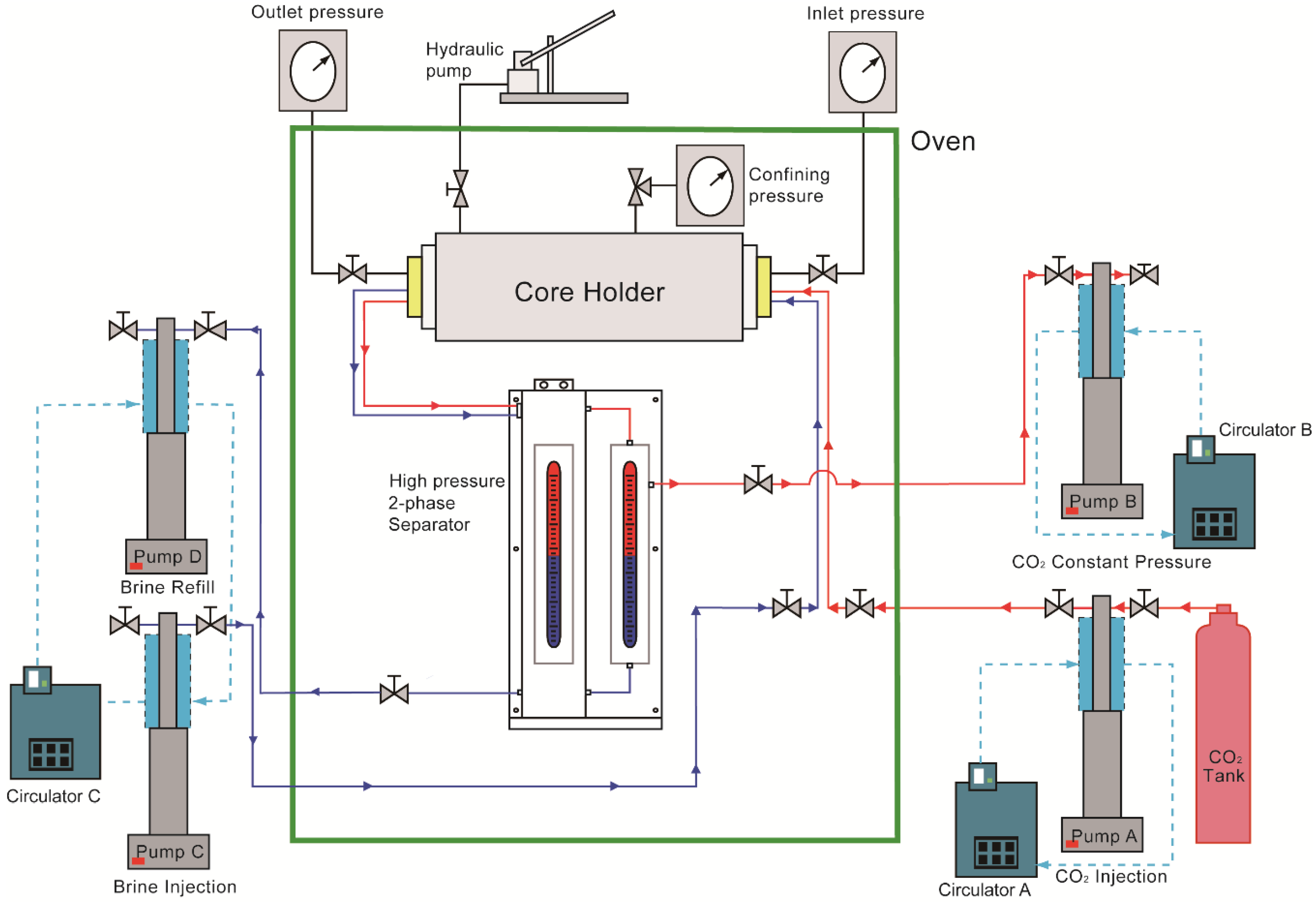
2.1. Experimental Apparatus

Figure 2 shows the experimental apparatus based on previous work [31] that was used for measuring the endpoint relative permeability of CO2 and residual brine saturation through the steady-state technique. The CO2 and brine were circulated through the core by a pump system. Pumps A and C were used, respectively, to inject brine and CO2 at a constant flow rate. Temperature control jackets covered the pump bodies so that the circulator could maintain the fluid at a constant temperature.
A temperature-controlled, air-forced circulation oven housed the core holder, high-pressure separator, and flow lines. The high-pressure separator was used to measure fluid saturation, which consisted of two precision bore tubes. One tube acted as a separator in which the CO2 and brine were separated based on their density difference. The other was a sensing tube, where the curvature of the CO2/brine interface was undisturbed by any flow rates. Each separator had a level gauge measuring the height of the interface between the CO2 and brine throughout the experiment. Because the volumes of CO2 and brine in the system were constant during the test, the core saturation could be calculated from the material balance based on the position of the CO2/brine interface in the separator.
The core sample was wrapped with lead foil, and urethane was used as a sleeve material so that CO2 could not diffuse through the sleeve. With a hydraulic pump, water was introduced into the annulus space between the sleeve and core holder wall to generate constant confining pressure, which represented the in-situ pressure condition. After separation from produced fluids, the CO2 was sent again to the CO2 pump (Pump B) and the brine was connected to the brine pump (Pump D). Pump B was operated at constant pressure to maintain the stabilized pore pressure.

2.2. Experimental Condition

All data presented in this experiment were obtained from Berea sandstone with a length of 0.203 m and a diameter of 0.0381 m. Berea sandstone is widely used as a standard core flooding material because it is relatively homogeneous and commercially available [32]. Before the core flooding experiment, the core was fired at 873.15 K for 61,200 s to prevent the clay from swelling [33]. Porosity and absolute permeability of the core were measured with brine as 18.6% ± 0.4% and 7.105 ± 0.197 × 10⁻¹⁴ m2, respectively, as shown in Table 2. Table 2 also summarizes the fluid properties that represent the typical range of geological CO2 storage conditions [34,35,36]. During the experiment, pure CO2 and 5 wt % aqueous brine solution were used for the non-wetting and wetting phases, respectively.
Table 3 summarizes the experimental conditions in this study. In all experiments, flow rates were changed from 0.067 × 10⁻⁶ to 1.333 × 10⁻⁶ m3/s under a constant pressure of 8.57 MPa and a temperature of 328.15 K. These flow rates ensured that the capillary end effect did not influence the relative permeability [28].

2.3. Experimental Procedure

Once the core sample was pressurized to meet the experimental conditions, CO2-saturated brine (live brine) was injected to displace the CO2-unsaturated brine (dead brine) completely. Pure CO2 was subsequently introduced to the brine-saturated core while the flow rate was gradually increased from 0.067 × 10⁻⁶ to 1.333 × 10⁻⁶ m3/s to investigate its effect on the endpoint relative permeability of CO2. CO2 injection for each flow rate continued until the criteria of less than 1% variation in both the pressure drop and brine saturation were met.
For each injection rate, the effective permeability of CO2 was calculated using the Darcy equation shown in Equation (1) once the fluid saturation and pressure drop across the core sample were stabilized (steady-state), and the relative permeability was calculated using the absolute permeability in Equation (2).
q c o 2 = k e c o 2 A μ c o 2 d p d l ,
k r c o 2 = k e c o 2 k a ,
where ka, ke, and kr are the absolute, effective, and relative permeability, respectively; q is the volumetric flow rate; μ is the viscosity; A and l are the area and length of the core sample, respectively; and p is the pressure measured at inlet and outlet points. CO2 saturation in the core sample can be determined by reading the separator’s level difference shown in Figure 2.

3. Results and Discussion

Figure 3 shows the measured pressure drops at the various flow rates in this study. CO2 is injected until the flow is stable, with the measured pressure drop being converged. Although each measured data set seemed to have some fluctuations during each flow rate condition, the final pressure drop values at the end of the flow rate were obtained with sufficient convergence. The pressure drop trends showed that a reasonable relation was established between the flow rate and the pressure drop.
The Reynolds number, defined by Equation (3) as the inertial and viscous forces ratio, is used to investigate the flow regime in porous media under the experimental conditions.
Re = ρ v d μ
where μ is the viscosity, ρ is the fluid density, v is the Darcy velocity, and d is the grain size for the porous media. The values of 0.0005 m and 231 kg/m3 were used for the grain size of Berea sandstone and CO2 density, respectively, under the experimental conditions. The Reynolds number varies between 0.3 and 7.0, which is lower than 10 as the laminar flow upper boundary condition [37]; therefore, we conducted all experiments under the laminar flow conditions.
Figure 4 shows the plot of the endpoint relative permeability of CO2 versus the residual brine saturation obtained from the experiments. All the results are consistent with the characteristics mentioned above, having a lower endpoint relative permeability of CO2 and a higher residual saturation than the typical oil/water system. One reason for the low relative permeability and high residual saturation is the high capillary pressure due to the high interfacial tension shown in Table 2. In other words, the wetting phase (brine) tends to adhere strongly to rock surfaces and pore throats; therefore, the relative permeability of the CO2/brine system is characterized by high irreducible brine saturation and low CO2 relative permeability, which is different from those of the oil/water system.
The experimental result in Figure 4a reveals two essential features. The first is that the flow rate influences the endpoints. As the flow rate increases, the irreducible brine saturation decreases, and the endpoint of the relative permeability increases. The second is that the endpoint values converge as the flow rate increases. The changes in the endpoints at low flow rates are large, but the changes at high flow rates are not small. Therefore, the endpoint converges to a specific point, as shown in Figure 4b. The residual brine saturation asymptotically converges to 40%, and the endpoint relative permeability of CO2 approaches 0.45 as the flow rate increases.
The results were analyzed in terms of the capillary number defined as Equation (4).
N c = q μ σ
In this equation, q and μ are the Darcy velocity and viscosity of the displacing fluid (e.g., CO2 in this study), respectively; σ is the interfacial tension (IFT) between the displacing and displaced fluids. The capillary number is the dimensionless ratio of the viscous force and the capillary force. Figure 5 compares the residual saturation versus the capillary number of the typical oil/water system from the literature [38] and the CO2/brine system in this study.
Figure 5a was obtained from the imbibition test to describe the enhanced oil recovery with various flow rate conditions and the surfactant concentration that influences the interfacial tension [38]. The initial residual saturation of non-wetting fluid (oil) ranged from 25–30%, and the wetting fluid (water) with surfactant was injected into the cores to displace the oil. The y-axis represents the ratio of the final and initial oil saturations. The results of the oil/water system showed that water injections with surfactant can make the residual oil saturation nearly zero, which means the wetting fluid displaces all the non-wetting fluid in a high capillary number controlled by the IFT and flow rate. Figure 5b shows the results from the experiments of displacing brine by CO2 (drainage process) with different flow rates only. In this drainage process, the non-wetting fluid (CO2) cannot displace the wetting fluid (brine) as much as the imbibition case in Figure 5a. Even after the stabilization with CO2 injection, a significant amount of brine (over 40% of the brine saturation) still occupied pore spaces as not being displaced, even with high flow rate injection. Figure 5b also shows an apparent convergence, which is similar to Figure 4. Notably, the range of capillary numbers is much smaller than in Figure 5a. This means capillary phenomena and the relevant trapping mechanism are more influential in the CO2/brine system under the flow rate control condition.
The capillary and viscous forces can be used to explain the apparent convergence of endpoint values. In typical multiphase flows, the viscous force mainly affects the flow behavior, while the capillary force does so of the fluid trapped in the pore spaces [39]. Thus, the influences on the flowing system relate to the sweep efficiency of CO2-displacing brine. We employed the Brook–Corey model [40] and the Darcy equation to explain the behavior of the two forces relating to saturation changes. Equations (5) and (6) represent capillary and viscous forces, respectively.
p c = p c . e S w . e f f 1 λ = 2 σ c o s θ r
p = q c o 2 μ c o 2 L k e c o 2 A ,
where p c . e is the capillary entry pressure; λ is the pore size distribution index; r, σ , and θ are the pore radius, interfacial tension, and contact angle, respectively; A and L represent the flow area and length of the core sample, respectively; q c o 2 , μ r c o 2 , and k e c o 2 are flow rate, viscosity, and effective permeability of CO2, respectively; and S w . e f f is the adequate water saturation determined by Equation (7) with the current water saturation ( S w ) and irreducible water saturation ( S w i r r ).
S w . e f f = S w S w i r r 1 S w i r r
In Equation (6), the capillary entry pressure was measured as 0.0496 MPa when CO2 was forced to enter the core. This value is similar to the value of 0.0510 to 0.0572 MPa in the literature [41]. Moreover, λ = 2 was applied as the pore size distribution index, considering that the core as consolidated [42].
Figure 6 shows the capillary and viscous pressures at the experimental conditions. The increase in the viscous force with the flow rate makes the displacement of the brine more efficient. However, the increase in the capillary pressure is higher than that of the viscous pressure. This means that the capillary force influences the flow phenomena more than viscous force as the flow rate increases. In general, the capillary force works as a barrier to the drainage process. As a result, the increase in the endpoint relative permeability and the decrease in the residual saturation become smaller as the flow rate increases.
The behavior of the endpoint values shown in Figure 4b can be converted in terms of Darcy velocity, as shown in Figure 7. Figure 7 shows the relation between the endpoint trend and Darcy velocity of CO2 injection based on Figure 4b. Given the core area, the maximum flow rate of 1.333 × 10⁻⁶ m3/s in the experiments corresponds to 0.00115 m/s. With the data in Figure 7, the rate dependence of the relative permeability can be considered for CO2 injection into a reservoir.
Relative permeability depending on the flow rate significantly impacts the CO2 flow into the reservoir. Figure 8a shows a schematic of the CO2 injection into a reservoir. Assuming that the flow is under the steady-state for simplicity, the flow rate of CO2 should be constant through an area with any radius; that is to say, the flow rate of CO2 at the area with the radius r is equal to that with the radius R in Figure 8a. It follows that Darcy velocity is inversely proportional to the radius as Equation (8).
v r r =   v R R ,
where v r and v R represent the Darcy velocity at radius r and R , respectively. Then, the Darcy velocity at radius R is easily derived as r R v r .
Based on Figure 7, it is necessary to apply different endpoint values with different flow velocities in different radii of the reservoir. For example, it was assumed that the reservoir pressure and temperature are 20.68 MPa and 373.15 K, respectively, and 3.28 m3/s of CO2 is injected into a reservoir with a thickness of 15.24 m. Different values of the endpoint relative permeability and the residual saturation should be assigned with different radii from the well, as shown in Figure 8b. This shows that the brine displacement is limited, and the mobility of CO2 worsens as CO2 enters farther into the reservoir. For example, from the radius of forty times of the wellbore radius ( r ), the endpoint CO2 relative permeability is decreased by about 75% of that at the wellbore, and the residual brine saturation increases from 40% to 60%. The displacement of brine by CO2 in the reservoir is not expected to be as efficient in the vicinity of the wellbore. This phenomenon will cause the flowing bottom-hole pressure to increase during a continuous injection operation. Even if the maximum injection rate under the operational constraint is applied, the initial injection efficiency cannot be expected because CO2 goes in a radial direction with velocity decreasing in the reservoir.

4. Conclusions

In this study, the influence of the flow rate on the relative permeability was investigated experimentally in the CO2/brine system. The conclusions from the results are as follows.
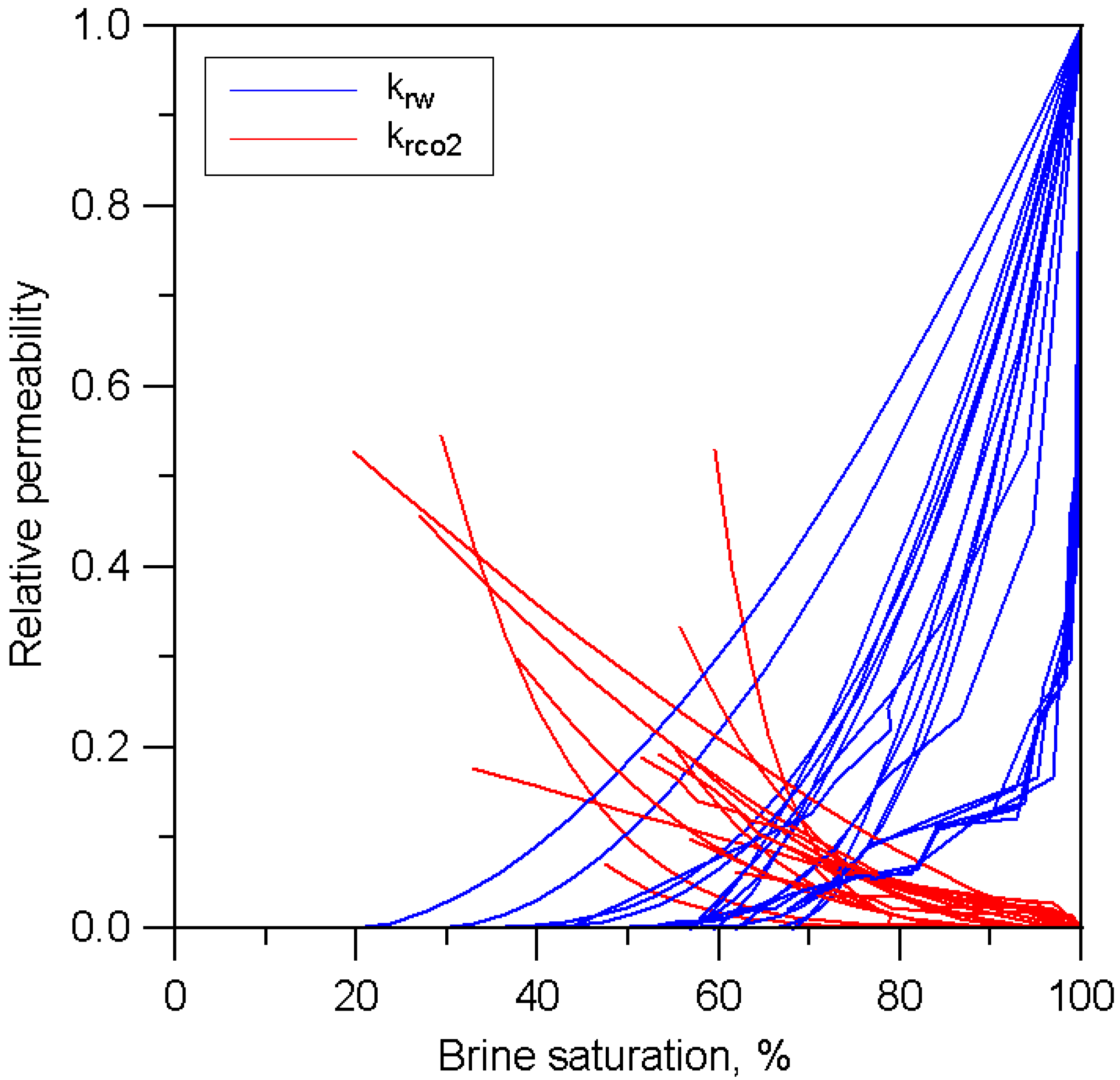
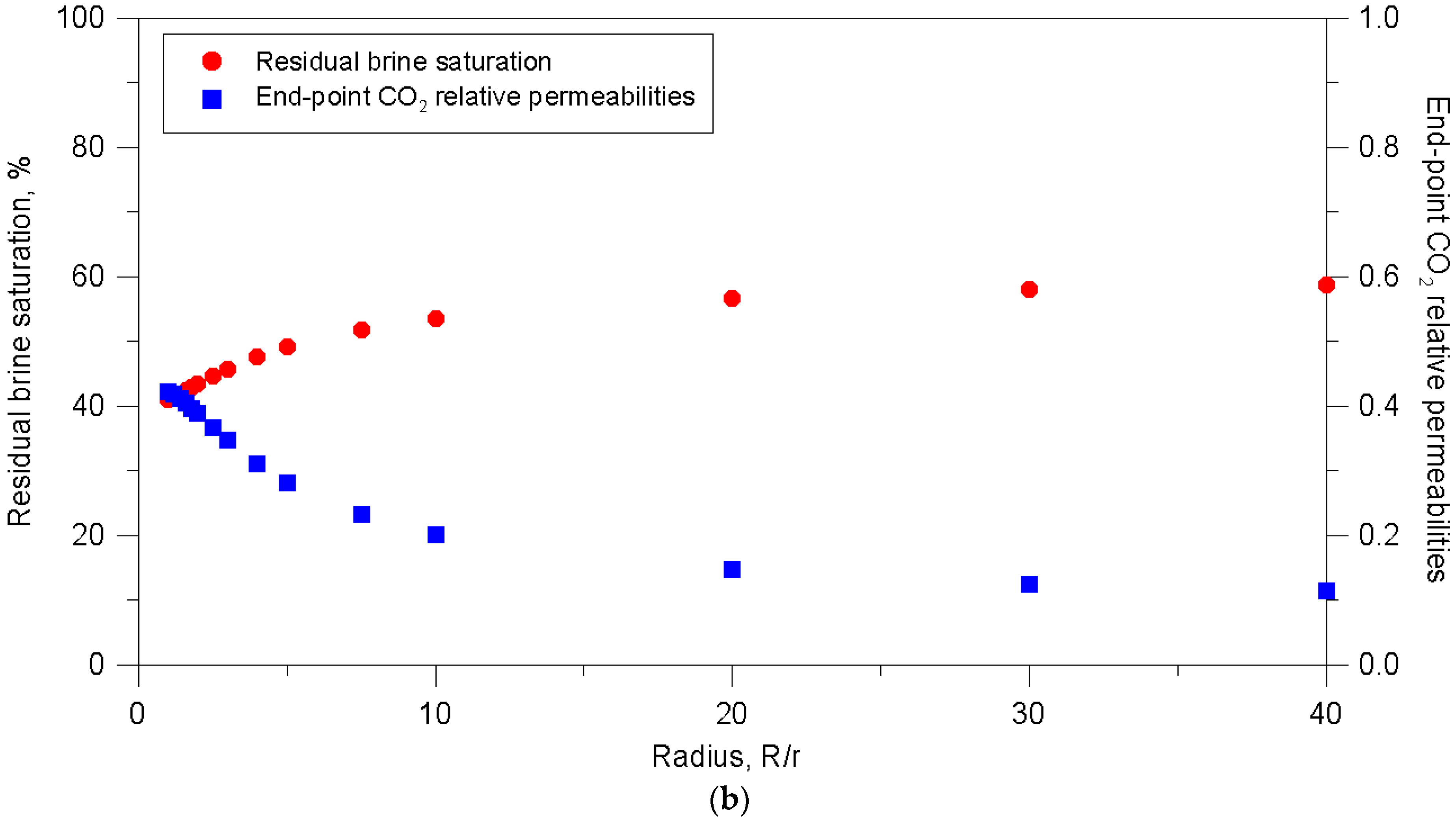
  • The CO2 endpoint relative permeability measured at all flow rates was less than 0.5, and the residual brine saturation rate was higher than 40%. These experimental results are consistent with the previous studies and are in sharp contrast to the oil/water system. They also show the dependence of CO2 injection rate: the measured endpoint relative permeability of CO2 increases with the measured irreducible brine saturation decreasing as flow rate increases.
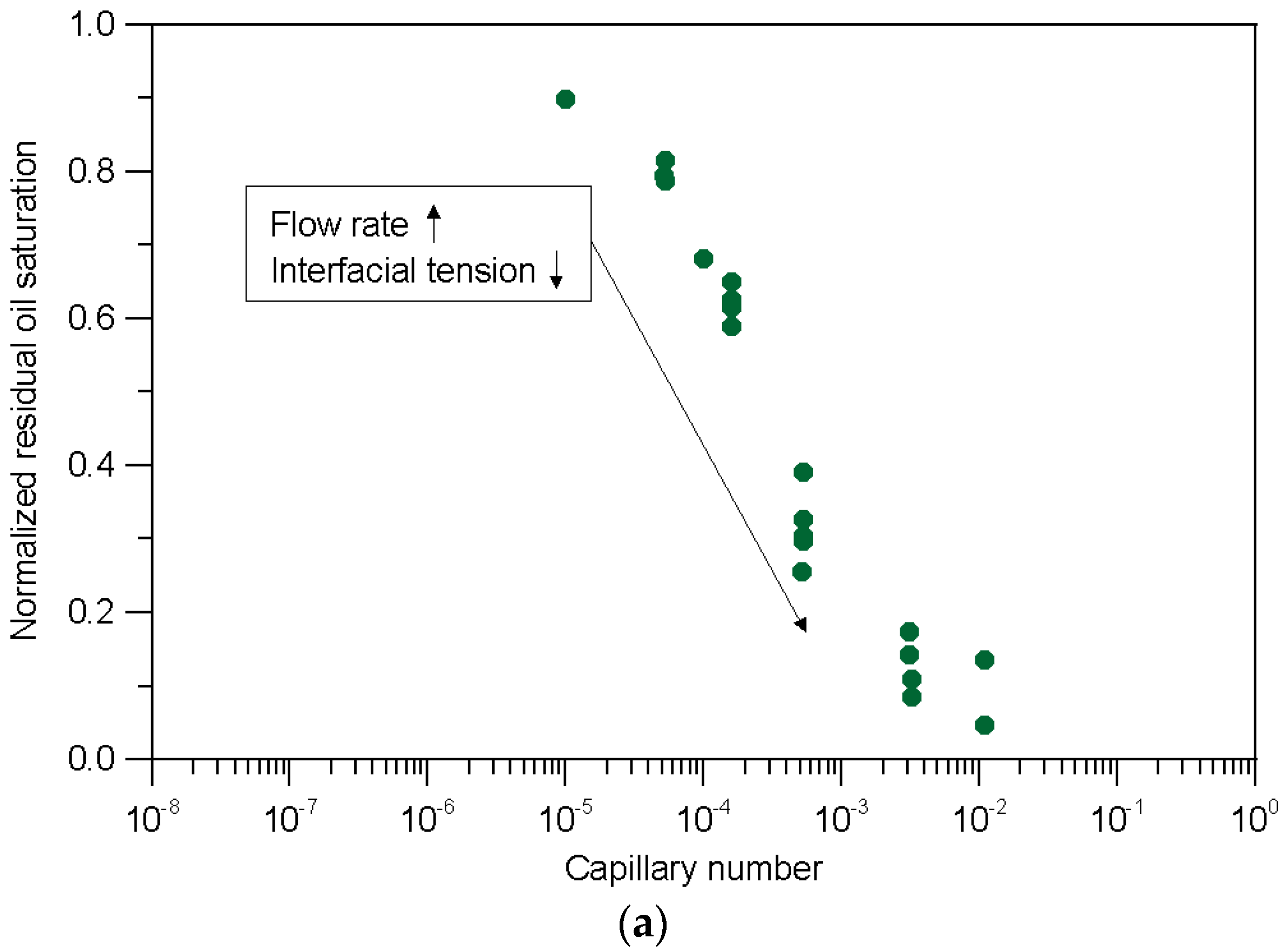
  • Although increasing flow rate causes the viscous force to increase linearly, capillary pressure increases sharply. From the experiments, we observed that the changes in the residual brine saturation and CO2 endpoint relative permeability are small in high flow rate conditions compared to the case of low flow rate conditions. This causes the CO2 endpoint relative permeability to converge to a specific value that limits the displacing process.
  • To estimate the storage capacity and flow efficiency of CO2 in reservoir simulation techniques, the changes in endpoint values along flow rate conditions should be considered. Letting the flow rate increase can cause a high injectable CO2 amount with low residual brine saturation. For this reason, the capacity of the injection pump and relevant facilities should be optimized based on the dependency of the relative permeability on the CO2 injection rate.

Author Contributions

Conceptualization, G.S.J.; experiment, G.S.J.; methodology, G.S.J. and S.K.; validation, D.S.L. and I.J.; investigation, G.S.J., I.J., and S.K.; resources, D.S.L. and I.J.; writing—original draft preparation, G.S.J. and S.K.; writing—review and editing, G.S.J., I.J., and S.K.; supervision, S.K. and I.J.; project administration, G.S.J.; funding acquisition, D.S.L. All authors have read and agreed to the published version of the manuscript.

Funding

This work was supported by the Energy Efficiency & Resources of the Korea Institute of Energy Technology Evaluation and Planning (KETEP) grant funded by the Korean government’s Ministry of Knowledge Economy (No. 20162010201980).

Institutional Review Board Statement

Not applicable.

Informed Consent Statement

Not applicable.

Data Availability Statement

Not applicable.

Conflicts of Interest

The authors declare no conflict of interest.

References

  1. IPCC (Intergovernmental Panel on Climate Change). IPCC Special Report on Carbon Dioxide Capture and Storage; Cambridge University Press: New York, NY, USA, 2005. [Google Scholar]
  2. Bachu, S. Screening and ranking of sedimentary basins for sequestration of CO2 in geological media in response to climate change. Environ. Geol. 2003, 44, 277–289. [Google Scholar] [CrossRef]
  3. Apps, J.A.; Zheng, L.; Zhang, Y.; Xu, T. Evaluation of potential changes in groundwater quality in response to CO2 leakage from deep geologic storage. Transp. Porous Media 2010, 82, 215–246. [Google Scholar] [CrossRef]
  4. Würdemann, H.; Möller, F.; Kühn, M.; Heidug, W.; Christensen, N.P.; Borm, G.; Schilling, F.R. CO2SINK—From site characterisation and risk assessment to monitoring and verification: One year of operational experience with the field laboratory for CO2 storage at Ketzin, Germany. Int. J. Greenh. Gas Control 2010, 4, 938–951. [Google Scholar] [CrossRef] [Green Version]
  5. Martens, S.; Liebscher, A.; Möller, F.; Würdemann, H.; Schilling, F.; Kühn, M. Progress report on the first European on-shore CO2 storage site at Ketzin (Germany)—Second year of injection. Energy Procedia 2011, 4, 3246–3253. [Google Scholar] [CrossRef] [Green Version]
  6. Honarpour, M.M.; Koederitz, L.; Harvey, A.H. Relative Permeability of Petroleum Reservoirs; CRC Press Ltd.: Boca Raton, FL, USA, 1986. [Google Scholar]
  7. Benson, S.; Pini, R.; Reynolds, C.; Krevor, S. Relative Permeability Analysis to Describe Multi-Phase Flow in CO2 Storage Reservoirs; No. 2; Global CCS Institute: Melbourne, Australia, 2013. [Google Scholar]
  8. Fulcher, R.A.; Ertekin, T.; Stahl, C.D. Effect of capillary number and its constituents on two phase relative permeability curves. J. Pet. Technol. 1985, 37, 249–260. [Google Scholar] [CrossRef]
  9. Krevor, S.C.M.; Pini, R.; Zuo, L.; Benson, S.M. Relative permeability and trapping of CO2 and water in sandstone rocks at reservoir conditions. Water Resour. Res. 2012. [Google Scholar] [CrossRef]
  10. Perrin, J.C.; Krause, M.; Kuo, C.W.; Milijkovic, L.; Chabora, E.; Benson, S.M. Core-scale experimental study of relative permeability properties of CO2 and brine in reservoir rocks. Energy Procedia 2009, 1, 3515–3522. [Google Scholar] [CrossRef] [Green Version]
  11. Bennion, B.; Bachu, S. Drainage and imbibition relative permeability relationships for supercritical CO2/brine and H2S/brine systems in intergranular sandstone carbonate shale and anhydrite rocks. SPE Reserv. Eval. Eng. 2008, 11, 487–496. [Google Scholar] [CrossRef]
  12. Bachu, S. Drainage and imbibition CO2/brine relative permeability curves at in situ conditions for sandstone formations in western Canada. Energy Procedia 2013, 37, 4428–4436. [Google Scholar] [CrossRef] [Green Version]
  13. Shi, J.Q.; Xue, Z.; Durucan, S. Supercritical CO2 core flooding and imbibition in Berea sandstone—CT imaging and numerical simulation. Energy Procedia 2011, 4, 5001–5008. [Google Scholar] [CrossRef] [Green Version]
  14. Richardson, J.G.; Kerver, J.K.; Hafford, J.A.; Osoba, J.S. Laboratory determination of relative permeability. J. Pet. Technol. 1952, 4, 3375–3385. [Google Scholar] [CrossRef]
  15. Johnson, E.F.; Bossler, D.P.; Naumann, V.O. Calculation of relative permeability from displacement experiments. Trans. AIME 1959, 216, 370–372. [Google Scholar] [CrossRef]
  16. Jones, S.C.; Roszelle, W.O. Graphical techniques for determining relative permeability from displacement experiments. J. Pet. Technol. 1978, 30, 807–817. [Google Scholar] [CrossRef]
  17. Levine, J.S.; Goldberg, D.S.; Lackner, K.S.; Matter, J.M.; Supp, M.G.; Ramakrishnan, T.S. Relative permeability experiments of carbon dioxide displacing brine and their implications for carbon sequestration. Environ. Sci. Technol. 2014, 48, 811–818. [Google Scholar] [CrossRef] [PubMed] [Green Version]
  18. Müller, N. Supercritical CO2-brine relative permeability experiments in Reservoir Rocks—Literature Review and Recommendations. Transp. Porous Media 2011, 87, 367–383. [Google Scholar] [CrossRef]
  19. Perrin, J.C.; Benson, S. An experimental study on the influence of sub-core scale heterogeneities on CO2 distribution in reservoir rocks. Transp. Porous Media 2010, 82, 93–109. [Google Scholar] [CrossRef]
  20. Pini, R.; Benson, M. Simultaneous determination of capillary pressure and relative permeability curves from core-flooding experiments with various fluid pairs. Water Resour. Res. 2013, 49, 3516–3530. [Google Scholar] [CrossRef]
  21. Jeong, G.S.; Lee, J.; Ki, S.; Huh, D.; Park, C. Effects of viscosity ratio, interfacial tension and flow rate on hysteric relative permeability of CO2/brine systems. Energy 2017, 133, 62–69. [Google Scholar] [CrossRef]
  22. Soriush, M.; Wessel-Berg, D.; Torasaeter, O.; Kleppe, J. Investigating impact of flow rate and wettability on residual trapping in CO2 storage in saline aquifers through relative permeability experiments. Energy Environ. Res. 2013, 3, 53–72. [Google Scholar] [CrossRef]
  23. Osoba, J.S.; Richardson, J.G.; Kerver, J.K.; Hafford, J.A.; Blair, P.M. Laboratory measurements of relative permeability. J. Pet. Technol. 1951, 3, 47–55. [Google Scholar] [CrossRef]
  24. Richardson, J.G. The calculation of waterflood recovery from steady-state relative permeability data. J. Pet. Technol. 1957, 9, 64–66. [Google Scholar] [CrossRef]
  25. Sandberg, C.R.; Gourney, L.S.; Suppel, R.F. Effect of fluid flow rate and viscosity on laboratory determination of oil-water relative permeabilities. Trans. AIME 1958, 213, 36–43. [Google Scholar] [CrossRef]
  26. Alizadeh, A.H.; Keshavarz, A.; Haghighi, M. Flow rate effect on two-phase relative permeability in Iranian carbonate rocks. In Proceedings of the SPE Middle East Oil and Gas Show and Conference, Manama, Bahrain, 11–14 March 2007. [Google Scholar] [CrossRef]
  27. Owens, W.W.; Parrish, D.R.; Lamoreaux, W.E. An evaluation of a gas drive method for determining relative permeability relationships. Trans. AIME 1956, 207, 275–280. [Google Scholar] [CrossRef]
  28. Hadley, G.F.; Handy, L.L. A theoretical and experimental study of the steady state capillary end effect. In Proceedings of the Fall meeting of the petroleum branch of AIME, Los Angeles, CA, USA, 14–17 October 1956. [Google Scholar] [CrossRef]
  29. Perkins, F.M. An investigation of the role of capillary forces in laboratory waterfloods. J. Pet. Technol. 1957, 9, 49–51. [Google Scholar] [CrossRef]
  30. Kyte, J.R.; Rapoport, L.A. Linear waterflood behavior and end effects in water-wet porous media. J. Pet. Technol. 1958, 10, 47–50. [Google Scholar] [CrossRef]
  31. Jeong, G.S.; Choi, J.; Lee, D.S.; Ki, S. Analysis of CO2 and brine relative permeability of in-situ core samples with employing double separator. Geosci. J. 2020. [Google Scholar] [CrossRef]
  32. Churcher, P.L.; French, P.R.; Shaw, J.C.; Schramm, L.L. Rock properties of Berea sandstone, baker dolomite, and indiana limestone. In Proceedings of the SPE International Symposium on Oilfield Chemistry, Anaheim, CA, USA, 20–22 February 1991. SPE-21044-MS. [Google Scholar]
  33. Ma, S.; Morrow, N.R. Effect of firing on petrophysical properties of Berea sandstone. SPE Form. Eval. 1994, 9, 213–218. [Google Scholar] [CrossRef]
  34. McCain, W.D. Reservoir fluid property correlations-state of the art. SPE Reserv. Eng. 1991, 6, 266–272. [Google Scholar] [CrossRef]
  35. National Institute for Standards and Technology (NIST) Chemistry Webbook. Available online: https://webbook.nist.gov/chemistry/fluid/ (accessed on 1 September 2020).
  36. Bennion, D.B.; Bachu, S. Correlations for the interfacial tension between supercritical phase CO2 and equilibrium brines at in situ conditions. In Proceedings of the SPE Annual Technical Conference and Exhibition, Denver, CO, USA, 21–24 September 2008. SPE-114479-MS. [Google Scholar]
  37. Wang, L.; Li, Y.; Zhao, G.; Chen, N.; Xu, Y. Experimental investigation of flow characteristics in porous media at low Reynolds numbers (Re → 0) under different constant hydraulic heads. Water 2019, 11, 2317. [Google Scholar] [CrossRef] [Green Version]
  38. Gupta, S.P.; Trushenski, S.P. Micellar flooding—Compositional effects on oil displacement. Soc. Pet. Eng. J. 1979, 19, 116–128. [Google Scholar] [CrossRef]
  39. Lake, L.; Johns, R.T.; Rossen, R.; Pope, G.A. Fundamentals of Enhanced Oil Recovery; Society of Petroleum Engineers: Richardson, TX, USA, 2014. [Google Scholar]
  40. Brooks, R.H.; Corey, A.T. Properties of porous media affecting fluid flow. J. Irrig. Drain. Div. 1966, 92, 61–68. [Google Scholar]
  41. Dullien, F. Porous media: Fluid Transport and Pore Structure; Academic Press: San Diego, CA, USA, 1979. [Google Scholar]
  42. Corey, A.T. The interrelation between gas and oil relative permeabilities. Prod. Mon. 1954, 19, 38–41. [Google Scholar]
Figure 1. All of the CO2/brine relative permeability data from the literature [9,10,11,12].
Sustainability 13 01543 g001
Figure 2. Experimental apparatus modified for two-phase core flooding experiments (modified from Jeong et al. [31]).
Sustainability 13 01543 g002
Figure 3. The measured pressure drop across the core sample.
Sustainability 13 01543 g003
Figure 4. Endpoint changes according to flow rate change: (a) endpoint of kr-CO2 (modified from Jeong et al. [21]), (b) convergence of residual brine saturation and kr values.
Sustainability 13 01543 g004
Figure 5. Residual saturation, according to capillary number (a) oil/water system (imbibition) (modified from Gupta and Trushenski [38]) and (b) CO2/brine system (drainage) (this study).
Sustainability 13 01543 g005aSustainability 13 01543 g005b
Figure 6. Comparison of calculated capillary pressure and viscous pressure drop for CO2/brine on Berea sandstone.
Sustainability 13 01543 g006
Figure 7. Endpoint changes according to Darcy velocity based on Figure 4.
Sustainability 13 01543 g007
Figure 8. Effect of endpoint changes: (a) schematic diagram of CO2 injection into a reservoir; (b) endpoint property changes with the radius of the reservoir.
Sustainability 13 01543 g008aSustainability 13 01543 g008b
Table 1. Summary of data acquisition for CO2/brine relative permeability.
ReferenceSample NameEndpoint Relative Permeability (krCO2)Residual Brine Saturation (Swirr)
Krevor et al., 2012 [9]Berea sandstone0.39480.4438
Paaratte0.32840.3894
Mt. Simon0.49290.4371
Tuscaloosa0.07670.7030
Perrin and Benson, 2010 [10]Otway sandstone0.65940.4370
Berea sandstone0.07000.5890
Bennion and Bachu, 2008 [11]Cardium #10.52600.1970
Cardium #20.12900.4250
Viking #10.33190.5580
Viking #20.26380.4230
Ellerslie #10.11560.6590
Basal Cambrian #10.54460.2940
Bachu, 2013 [12]Ellerslie #20.57350.3820
Viking #30.09730.6010
Basal Cambrian #20.21050.5690
Basal Cambrian #30.15620.4900
Basal Cambrian #40.21000.6510
Basal Cambrian #50.32550.2750
Clearwater0.49390.3430
Rock Creek0.04340.4790
Halfway0.27330.4660
Belloy0.07620.6530
Graminia0.14610.4420
Gilwood0.54540.5655
Deadwood #10.10620.4897
Deadwood #20.09410.5959
Deadwood #30.25970.6540
Granite Wash0.40500.5789
Shi et al., 2011 [13]Tako Sandstone0.13500.5700
Mean 0.27880.4952
Standard Deviation 0.18460.1268
Table 2. Rock and fluid properties.
RockFluids
SamplePorosityPermeabilityCO2 ViscosityBrine ViscosityInterfacial Tension
Berea sandstone18.6% ± 0.4%7.105 ± 0.197 × 10⁻¹⁴ m20.000021 Pa·s0.00058 Pa·s36.9 mN/m
Table 3. Experimental conditions of flow rate.
Experimental Run1234567891011121314
Flow rate
(×10−6 m3/s)
0.0670.1330.2000.2670.3330.4000.4670.5330.6000.6670.8331.0001.1671.333
Publisher’s Note: MDPI stays neutral with regard to jurisdictional claims in published maps and institutional affiliations.

