Article

Analysis of Inlet Configurations on the Microclimate Conditions of a Novel Standalone Agricultural Greenhouse for Egypt Using Computational Fluid Dynamics

1
Department of Engineering, University of Exeter, Exeter EX4 4QF, UK
2
City of Scientific Research and Technological Applications (SRTA), Alexandria 21934, Egypt
3
Ex-Environmental Engineering Department, School of Energy Resources, Environment, Chemical and Petrochemical Engineering, Egypt-Japan University of Science and Technology, Alexandria 21934, Egypt
4
Department of Mechanical Power Engineering, Zagazig University, Zagazig 44519, Egypt
5
Water and Water structures Engineering Department, Faculty of Engineering, Zagazig University, Zagazig 44519, Egypt
*
Authors to whom correspondence should be addressed.
Sustainability 2021, 13(3), 1446; https://doi.org/10.3390/su13031446
Submission received: 10 December 2020 / Revised: 23 January 2021 / Accepted: 27 January 2021 / Published: 30 January 2021

Abstract

:
Water shortage, human population increase, and lack of food resources have directed societies towards sustainable energy and water resources, especially for agriculture. While open agriculture requires a massive amount of water and energy, the requirements of horticultural systems can be controlled to provide standard conditions for the plants to grow, with significant decrease in water consumption. A greenhouse is a transparent indoor environment used for horticulture, as it allows for reasonable control of the microclimate conditions (e.g., temperature, air velocity, rate of ventilation, and humidity). While such systems create a controlled environment for the plants, the greenhouses need ventilation to provide fresh air. In order to have a sustainable venting mechanism, a novel solution has been proposed in this study providing a naturally ventilating system required for the plants, while at the same time reducing the energy requirements for cooling or other forced ventilation techniques. Computational fluid dynamics (CFD) was used to analyse the ventilation requirements for different vent opening scenarios, showing the importance of inlet locations for the proposed sustainable greenhouse system.

1. Introduction

Production of fresh horticultural crops in greenhouses is an essential agricultural practice. The use of greenhouses results in increased harvest, water and nutrients, higher fruit yield, longer production times, and the capacity to grow off-season [1]. They are being used to protect the plants from severe climate conditions such as high wind rates, intense sunshine, and high levels of temperature and humidity [2,3]. Such different parameters may be managed simply by opening/closing vents automatically or manually to control wind speeds, or even by choosing proper covering materials [4,5]. Using dyed glass can prevent high solar irradiance from impacting plant growth by shielding the greenhouse (GH)’s translucent walls and roof [3].
Although a mono-span known as a walk-in greenhouse is a common greenhouse structure in Egypt, many other types of greenhouse have been developed over the last 25 years, such as the double-span, the Parron system, wooden greenhouses, and the multi-span. However, double-span greenhouses are the most widely used, with their sufficient ventilation and simple management, according to growers in Egypt [1]. Greenhouses covered with screen nets or shade nets are frequently used in Egypt, especially during hot summer days, to reduce the radiation intensity in the greenhouse. Additionally, shading screens used inside the glasshouses caused the reduction of photosynthetically active radiation leading to the better quality of agricultural production [6,7,8,9]. A screen shade net can be placed outside on top of the greenhouse (using proper construction) and would be effective in minimising heat load from crops grown in the greenhouse [10,11]. The design and sustainability of the greenhouse in Egypt must consider both high temperatures on hot days in summer, low air temperatures at night in winter, and insufficient humidity levels, especially in the south of the country, throughout the whole year [12]. The natural greenhouse ventilation is built with netting on the edges, as well as one- or two-sided openings on the top floor. The top openings can be versatile to enable it to open or close, depending on the environment. Fogging can be applied inside the greenhouse for cooling and increasing relative air humidity. Applying a fogging system may also reduce crop evapotranspiration, but total water use may be the same because water is required for fogging itself [13]. Egypt has imported a range of greenhouses from countries that have highly developed greenhouse technology, such as the Netherlands, Spain, China, and Hungary, as part of its national project for 100,000 greenhouses. The Egyptian decision-makers evaluated the suitability of these greenhouses for conditions in Egypt based on the agricultural sector’s experience with manufactured greenhouse systems [1].
One of the most significant issues in Mediterranean greenhouses is that from early spring to the end of autumn, there are extremely high interior temperatures during the day. These have negative impacts on the yield and quality of nearly every greenhouse crop. The main reason for those high temperatures is generally insufficient ventilation [14]. In semi-arid regions, control of the inner temperature and relative humidity is crucial in order to maintain the photosynthetic and transpiration rates of plants [15]. Forced ventilation is not economical due to its energy consumption and maintenance costs. Natural ventilation is a cheaper and more reasonable method and is very commonly used in both summer and winter to ensure a nearly optimal greenhouse climate [16]. Indoor microclimate regulation is thus a central concern in analysing the greenhouses, and natural ventilation plays a key role in indoor climate control as it directly influences heat and mass exchanges between the outside environment and the greenhouse. Vent measurements and locations are important elements in the design of natural ventilation. The correlations between ventilation rates and environmental parameters were evaluated with various approaches, including wind speed and direction [17]. Decay-rate tracer nitrate techniques were used in a single-span greenhouse with a circular arch roof and vertical walls to experimentally examine the vent form and screening effect on airflow and temperature distribution. It was observed that the indoor air velocity exhibited a rapid flow near the ground and low velocity near the roof in the case of side openings alone, while the combination of roof and side openings resulted in increase in air velocity and a reduction in indoor temperature, together with a higher microclimate heterogeneity [18]. The basic energy balance of a large greenhouse in a hot climate is calculated based on values of indoor and outdoor air temperature and humidity, outside global solar radiation, and measured wind speed and direction over significant periods, thus determining ventilation fluxes. Measurements of airspeed through vents and inside the greenhouse were also conducted to determine patterns of air movement [19]. Convection within greenhouses has been researched experimentally and numerically [20,21]. Higher indoor air temperatures are needed during cold weather for optimum plant growth and can be achieved by retaining the greenhouse effect or using some effective heating technology. On the other hand, in relatively hot climates, the greenhouse effect is needed only for a limited period of time spanning from around two to three months [22,23]. Many types of greenhouse have been used at different latitudes to grow off-season vegetables in different regions [24].
The greenhouse effect is not sufficient for all months of the year [25]. During summer, the mean air temperature in the Arabian Peninsula typically reaches 45 °C with insufficient relative humidity [26]. For instance, in Iraq during summer, ambient air temperatures can reach nearly 50 °C, making the solar greenhouse in this period unworkable. To attempt to resolve this situation, a system consisting of one indirect evaporative heat exchanger and three pads as a direct evaporative refrigeration using groundwater has been suggested [22] as an efficient technique for decreasing the temperature of the air and increasing its humidity to meet the climatic conditions needed for agriculture [23]. Greenhouse crops are mainly warm-season crops that are suited to maximum air temperatures between 17 and 27 °C, with minimum and maximum nominal temperatures between 10 °C and 35 °C. The GH indoor temperature without a climate controller could be 20–30 °C higher than the outside under hot and humid tropical climate conditions, while the air temperature may rise to 38 °C. A temperature above 26 °C is identified as a failure value and indicated that values over 25 °C would most likely reduce the yield of tomatoes. In addition, the maximum temperature of the greenhouse air should not exceed 30–35 °C [27].
Specific methodologies have been utilised in the study of natural greenhouse ventilation. Quantitative models were initially used to research natural ventilation in urban and industrial buildings and were used to establish realistic methodologies for quantifying greenhouse ventilation levels [28]. One of the methodologies commonly used to research this process is computational fluid dynamics (CFD), which, as opposed to laboratory experiments, can provide fast and reliable simulations at lower cost [29]. This simulation method has allowed a comprehensive explanation of the flow fields and thermal distribution in several greenhouses. It should be noted that relatively few transient CFD experiments are able to simulate the complex scenarios of shifts in wind speed and distance, as well as temperature [30].
Structures in agriculture such as greenhouses and ventilation mechanisms play a crucial role in climate and environmental control. Ventilation not only induces transfer of heat and humidity between the greenhouse and the ambient environment, but also leads to supplying fresh air to prevent the shortage of indoor carbon dioxide. Nowadays, there are many ventilation strategies in operation. However, due to its low cost and reduced energy consumption, natural ventilation is becoming more and more popular in the field. Nonetheless, there are several factors that influence inherent ventilation efficiency, with wind speed and wind direction having dominant effects [31]. Despite the significant amount of research undertaken to estimate the effect of wind speed on ventilation, the characteristics of airflow through the roof openings of a multi-span greenhouse are not adequately documented, especially concerning two important characteristics: namely, the effects of wind direction and magnitude on the flow patterns on the greenhouse opening planes and the detailed flow pattern at the crop level [32].
One study evaluated the efficiency of single-span commercial greenhouse ventilation according to the wind characteristics of reclaimed coastal lands, showing that the external wind patterns, along with the ratio of side vent area to greenhouse length, have a significant effect on the greenhouse’s natural ventilation [29]. This study also demonstrated that ventilation rates increase as the wind speed rises. Wind towers can be used for solar greenhouses to improve natural airflow and provide higher rates of airflow. Wind towers work based on pressure gradient (the difference in pressure between the windward and leeward sides). The windward side is characterised by positive pressure, which guides air into the structure, while the negative pressure on the leeward side leads air outwards [33]. An insect screen can substantially decrease indoor wind speed and increase the temperature and humidity inside the greenhouse. Their simulation results also showed that within the canopy region, the wind speed above the canopy is higher than its below [34]. Greenhouse conditions were simulated considering the fact that while the wind force existed, the ventilation rate of the naturally ventilated greenhouse was directly proportional to the scale of the sidewall opening and the wind speed. They also reported that insect screens and dense crop rows perpendicular to the airflow would significantly hinder greenhouse ventilation by the wind [35]. The effect of wind direction on the rate of ventilation of the Spanish “parral” greenhouse with two styles of roof openings was investigated; the findings revealed that in some situations, differences in wind direction of only 10 °C could improve ventilation by up to 50% [36]. The effects of wind direction on flow patterns and ventilation efficiency, compared with a single-span pitched-roofed greenhouse, were studied, and it was reported that the speed of ventilation and flow patterns in a single-span greenhouse with continuous roof vents depended on the wind direction and opening angles of windward and leeward wind [37].
Previous studies have mainly concentrated on greenhouses ventilated by roof and side vents and presented experimental results for the key factors of the greenhouse environment (including air velocity and air temperature), culminating in the compilation of a database for validating greenhouse ventilation analysis strategies for computational fluid dynamics (CFD) [38]. A discussion was presented on the efficiency of the various discretisation methods used as CFD solvers for simulating GH’s natural ventilation [39]. Ventilation is one of the main challenges of greenhouse construction, and it is possible to create a reasonable balance between ventilation and airspeed by means of careful CFD experiments [40]. The significance of analysing greenhouse air movements, caused by ventilation, and their effects on the uniformity of indoor microclimates are highly important. In reality, growers have increasingly managed to utilise any greenhouse region for high-quality yields, owing to the increasingly stronger global market rivalry [41]. At the same time, ventilation rates were lower when the wind speed increased, with subsequently more reduced air-exchange output due to inadequate matching of the supply air with the greenhouse air [42]. The sophistication and accuracy in both scientific experiments and simulations have been gradually improved, as recent tests compensate for all important greenhouse system variables [43]. One study used a 2D CFD analysis to examine the impact of a Chinese solar greenhouse segment resulting in longer sections producing higher internal temperatures than the shorter parts [44]. A two-dimensional analysis was performed on an Italian greenhouse and found that an open sidewall with a closed windward roof was the most vigorous airflow arrangement available, which eliminated 64% of the sun’s rays [45]. The main elements of greenhouse design are cladding material, and shape and faces of the greenhouse [46,47]. Therefore, in a realistic physical model, precise measurements of solar radiation, and mass and heat transfer coefficients are vital because these parameters have a direct effect on greenhouse energy and temperature [48,49]. The greenhouse interior space where microclimate conditions for plant growth should be adjusted is known as the greenhouse cavity. The key parameters for the cavity of the greenhouse need to be monitored: namely, temperature, relative humidity, concentration of carbon dioxide and photosynthetic photon flux in the air inside. Plants often require a 10–30 °C temperature range and 60–90% range of relative humidity [50]. If the temperature is above 30 °C, water stress will occur due to the amount of water loss through the leaves of the plants [51]. The same effect occurs by rapid transpiration at low relative humidity. On the other hand, water and nutrients are not transferred from the root zone due to the high relative humidity, which reduces the evaporation and transpiration levels of plants [52,53]. For greenhouses in a cold environment, during the daytime, the transmitted solar radiation inside the GH is absorbed and re-emitted during the night time to be captured by the GH cover, heating the air within the GH and thereby minimising or removing the heating power needed for GH operation. Unlike in cold climates, the solar radiation of the GH in a hot environment is higher than the comfort zone of the plants. This means that a cooling system should remove that extra solar radiation from the GH environment. The appropriate GH heating or cooling system usually depends on the location (ambient conditions) of the site [54]. If the outside temperature average is less than 10 °C, GH is likely to require heating, especially at night. If the average outside temperature is below 27 °C, during the day, ventilation will prevent excessive internal temperatures; however, if the average temperature exceeds 27–28 °C, then artificial cooling may be required [52]. In this paper, a CFD model was built to test the microclimate of the GH and to the test the different inlet ventilation scenarios on the indoor microclimate of the GH under construction in Egypt.

2. Materials and Methods
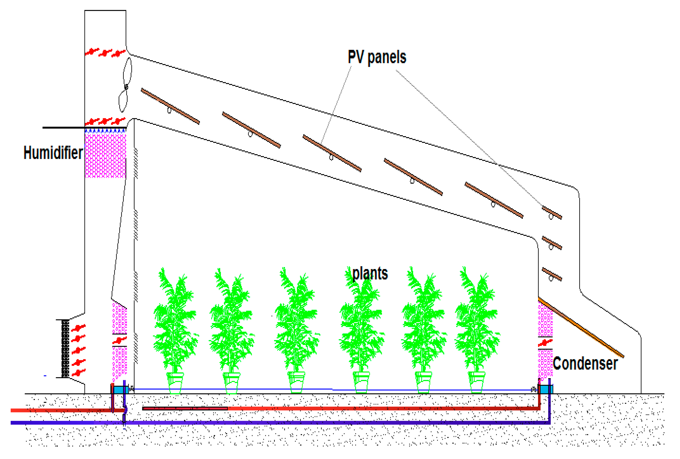
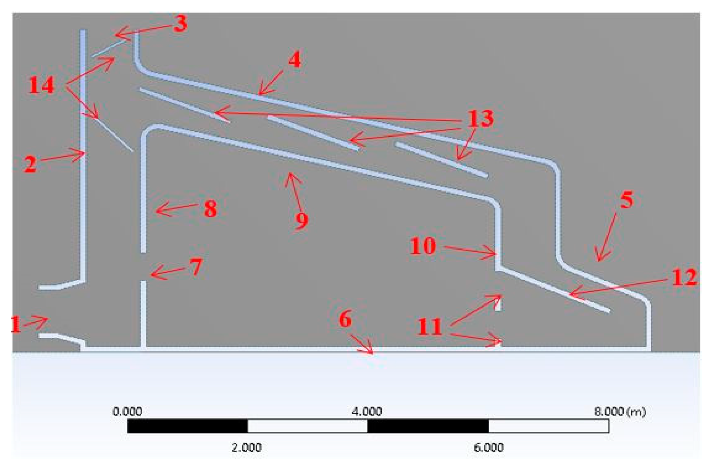
2.1. The GH Model

The conceptual greenhouse (GH) model in Figure 1 was modelled as a solar-powered desalination greenhouse in Egypt. In this GH, the solar energy is used to desalinate seawater using translucent solar still units mounted on the roof of the GH [55]. The plant transpiration, which is partly extracted utilizing a condenser that serves as a dehumidifier at the GH exit, is another outlet for water output. Salah et al. [55] have developed a mathematical model focused on mass and heat transfer equations to estimate GH efficiency based on the Clear Sky Day [56,57] solar radiation experiment. The condenser shown in Figure 1 is bypassed by 75% of the cavity air (i.e., just 25% of the GH cavity air moves through the condenser), and 90% of the GH cavity air is recirculated through the down-cup, which is blended with 10% fresh air before re-entering the GH cavity. The meteorological data used for that day were determined on the basis of average values for a period of 10 years (2004–2014) [58]. The input parameters used for the model are explained in Figure 1. In Egypt, the sun shines for 12h a day in the spring season, with an average strength of around 1000 W/m2. The solar stills (SS) can be used for desalination and generate a Zero Liquid Discharge (ZLD) model [59].

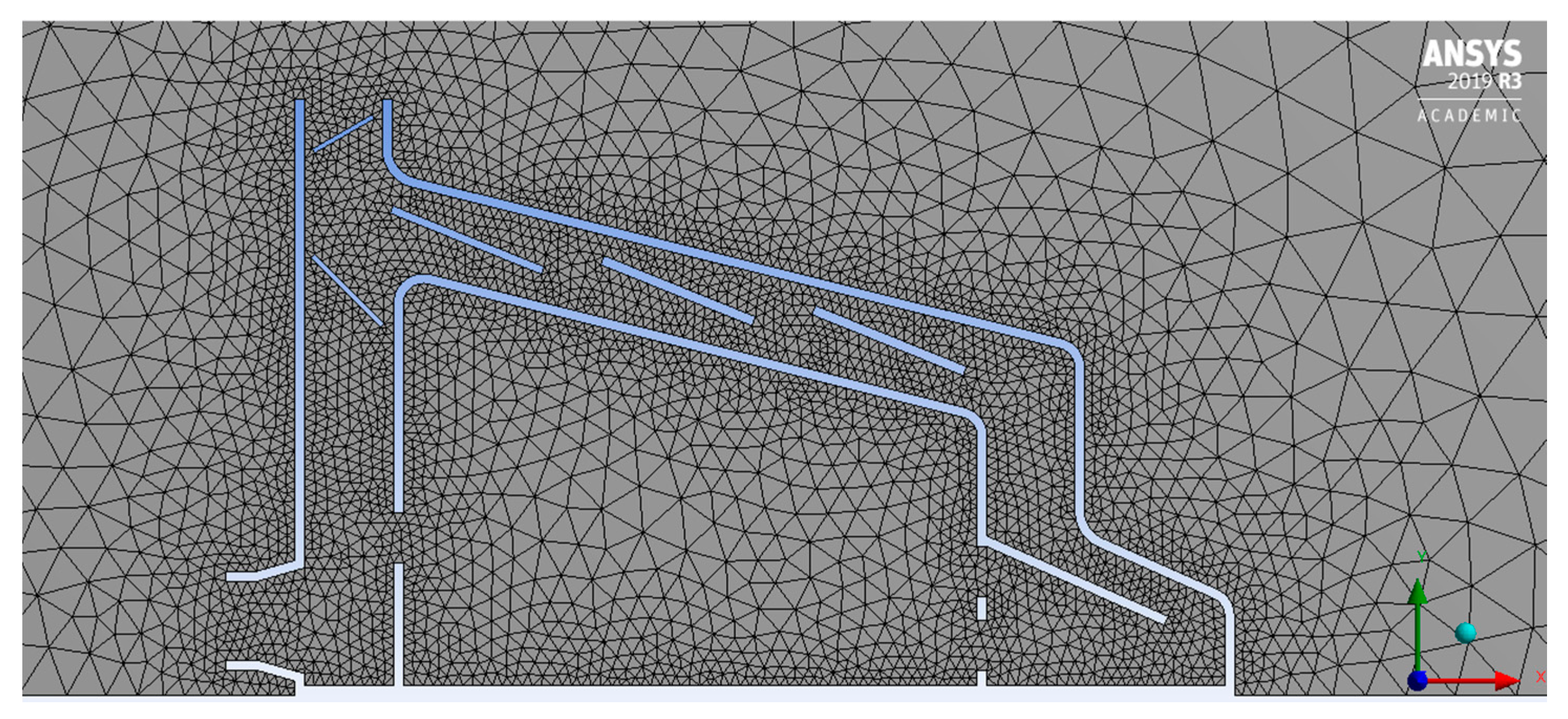
2.2. Building the GH Model with Ansys

The model of the greenhouse (GH) was designed with Ansys Fluent 19.3 as a 2D model. Primary analysis was conducted on the 2D GH, as the literature [61,62,63] found that 2D and 3D tests on wind perpendicular to the GH ridge provided comparable results for the cross-section perpendicular to the ridge. The simulations were conducted using a pressure-based solver, and steady-state analysis was completed in such a way that the results provided were time independent with a constant wind speed [64]. Gravity was allowed, with the gravity acceleration set at −9.81 ms−2 on the y-axis (vertical). The full GH dimensions can be found in Table 1, with a cross-section shown in Figure 2. The internal vent, number 7 in Figure 2, is being moved up and down for the CFD simulations to analyse how its position can influence the microclimate conditions within the GH.
To analyse the mesh sensitivity on the built CFD model, a mesh convergence analysis was performed on the geometry in Figure 3. Lower cell density was needed where strong gradients exist to minimise computational requirements without sacrificing precision, so controls of cell size were applied close to the GH walls in the model. The results were observed to converge at about 7514 triangular cells, with a maximum global element size of 5 mm and a maximum size of 50 mm for each edge of the geometry.
In this study, solar radiation was modelled using temperature and heat flux boundary conditions. The fluid properties were left as the default settings for both air and water. As the Boussinesq approximation was used in the model, the Boussinesq density was estimated using the same value as the constant fluid density, and the thermal expansion coefficient was also measured. The coefficient of thermal expansion of air was found to be 0.0034 K−1 at 25 °C [65], and the coefficient of thermal expansion of water was 0.000257 K−1 at 25 °C [66]. Throughout the simulations, the solids used were glass and soil. The material properties impacting the fluid movement and temperature calculations are the liquid pressure, and heat and thermal conductivity (see Table 2). The glass was added to both of the GH walls and roof edges, and the soil was introduced to the GH base. Nonetheless, these are just surface properties, as the wall thickness was not calculated to minimise the computational necessity; hence, the influence of the solid properties on the construct is minimal. The boundary conditions are chosen from the experimental measurements of Aiz et al.’s study for the 2D model (see Table 3) [39].
The original 2D model was used as the basis for the research, and in the study conducted, each model simulation had one parameter differing from the initial model, either in the model geometry or limit conditions. Different locations for the internal vents and different configurations [opening the lower vent, opening the upper vent, having both vents open, having the third and fourth vents open] were generated to investigate the effects on the air velocity and the temperature. The internal vents were studied for heights of 0.25 m and 1 m above ground at intervals of 0.25. There are 27 different scenarios for vent configurations with three temperature and three velocity values. The external wind speed was assigned at 2 m/s, 5 m/s, and 10 m/s to analyse the effect of the wind speed on the airflow patterns and temperature contours in the GH, while the air temperature was analysed for 290 K, 300 K, and 310 K in different scenarios.

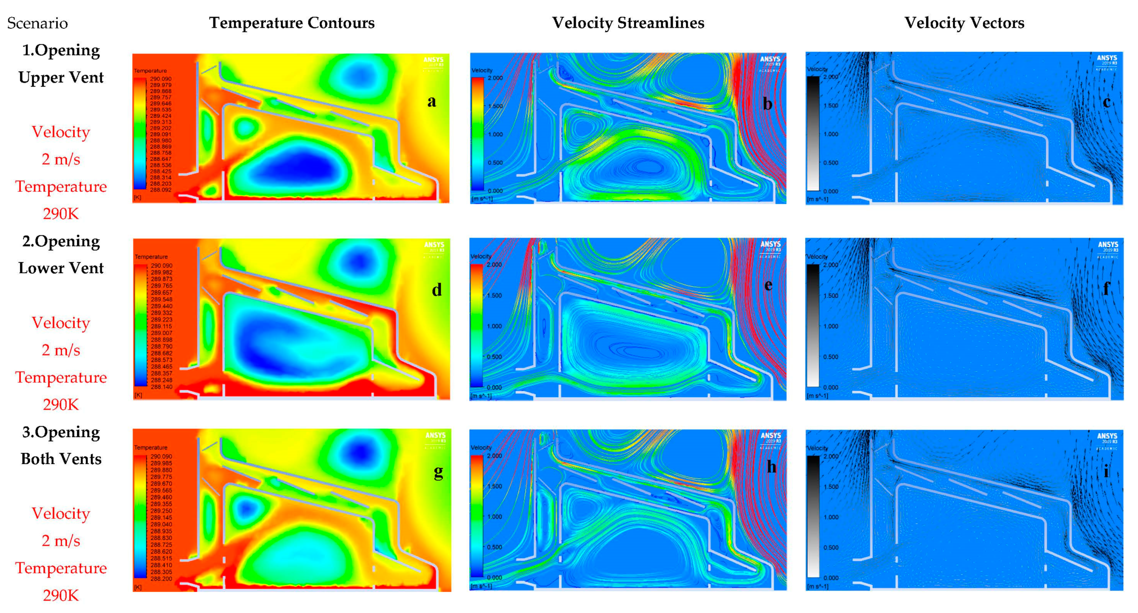
3. Results and Discussion

The air-flow patterns, velocity pathlines, and temperature contours produced by the simulation are in very close agreement with Sase et al.’s experimental work [63]. The temperature contours are distinctive, and this is possibly due to the particular form of ventilator used in the current study. Concerning quantitative validation against the previous studies, the maximum temperature for the current study is 320 K, while for the previous studies, a maximum value of 343 K was reported [55] with less than seven per cent deviation. For this analysis, the temperature range defined for plant growth is approximately 300–306 K, which is the maximum acceptable range for cultivation (average 308 K) [67]. As stated by Bartzanas et al. [68], the consequence of using pivoting ventilation is that the air flowing towards the ventilation will first flow around the ventilation itself, which allows the air to slow. The numerous airflow patterns caused by this type of vent can also be found in Shklyar and Arbel [37], which indicates similar trends to this paper.
The results of the 2D model (see Figure 4) demonstrate that the ambient air came through the main inlet on the left windward side of the greenhouse (GH) and then split into two parts. While the biggest part of it entered into the internal vent, the rest went directly to the main outlet. The internal air then moved up through the top of the GH and generated a central loop, while the air followed pathlines through the bottom of the vent, where it exited the GH main outlet at the top-left, reaching the solar stills.
The temperature contours in Figure 4a,g show that even though there was a loop in the centre of the greenhouse, smaller vortices occurred in the upper left corners. These caused sudden changes in temperature patterns in the GH. As a result of these changes, the natural ventilation conditions required for plants may not be met, and their growth may be negatively affected. On the other hand, as shown in Figure 4d, the temperature contours were more evenly distributed in the greenhouse in the scenario where the lower vent was open, which created a big loop in the centre. While the temperature of the air in the GH’s centre caused a difference of 1.5 K in Figure 4a, it was 0.75 K and 0.42 K in Figure 4d,g, respectively. It is seen that in the scenario where both vents were open, more air entered the greenhouse, causing an increase in temperature.
Although the air velocity was below 1.5 m/s in the greenhouse centre for all three images (Figure 4c,f,i), in Figure 4b,h, it did not exceed 1 m/s. According to the literature, the desired natural ventilation velocity should be between 0.5–1.0 m/s. However, it can be said that in Figure 4e the velocity vectors are more homogeneously and evenly distributed in the greenhouse. It was clearly seen that the airflow accelerated between the inner and outer roofs, and the velocity vectors became more prominent in these regions. This can be explained by the fact that the air hitting the surfaces accelerated in smooth corners. Inspection of the velocity paths revealed that the barriers placed under the main outlet prevented the air from coming out directly into the greenhouse.
It can be seen from Figure 5b,e,h that the increase in wind speed generally caused the temperature to rise in the greenhouse. Vortices still occured in the scenarios (see Figure 5a,g). However, the increase in the ambient air velocity caused the increase in the velocity of air entering the greenhouse and the continuity of the air circulation. The temperature difference remained between 288.227–289.780 K for the upper-ventilation-open scenario (see Figure 5a), while for the “lower vent open” and “two vents open” scenarios (see Figure 5a,d,g), it was 288.456–289.001 K and 288.620–289.565 K, respectively. However, the increase in velocity values had a considerable effect onthe changes of the velocity streamlines (see Figure 5b,e,h) and vectors (see Figure 5c,f,i). Additionally, the results showed that by increasing the inlet air velocity, the air speed within the greenhouse could reach 3.75 m/s. The effect of sudden and continuous velocity changes on the development of plants may be harmful. Additionally, just like the scenario in Figure 4g, the higher-velocity air flows through the two vents in Figure 5g caused the temperature to rise even more.
In the scenarios in Figure 6, the initial temperature was determined as 290 K, and the speed as 10 m/s. In this case, according to the temperature contours in the experiments, the temperature cycle formed in the greenhouse centre became smaller as compared with the previous two studies (see Figure 6a,d,g). While the temperature value was in the range of 288.724–289.941 K in Figure 5a, it was 288.330–289.798 K and 289.404–290.025 K in Figure 6d,g, respectively.
The remarkable situation here is that the optimum temperature distribution required for growing plants compared to the previous study (see Figure 6d–f). Almost all cases have a temperature change with clear contour lines. However, the temperature formed in the roof of the greenhouse reached almost the maximum level. In the scenario where both vents were open, relatively higher temperature values were obtained as compared with other cases. As this may affect the greenhouse’s natural cooling system, forced ventilation may be required.
Although there is not a noticeable difference in the velocity streamline scenarios (Figure 6b,e,h) and velocity vectors (Figure 6c,f,i), it can be said that the air joining the loop accelerated, and these scenarios will not be suitable for sustainable horticulture. Besides, although a visual change in velocity streamlines and vectors was not observed in these cases, this situation had an impact on the temperature distribution in the greenhouse. However, the velocity values in the greenhouse centre varied between 2.5 and 7.5 m/s in Figure 6.
Figure 7, Figure 8 and Figure 9 represent the data for the initial conditions of the “lower vent open”, “upper vent open”, and” both vents open” scenarios for 2 m/s, 5 m/s, 10 m/s velocity and 300 K temperature, respectively. It was clearly seen (see Figure 7a,d,g) that although the temperature values for all three cases gave inhomogeneous patterns in the greenhouse centre, the temperature distribution was different in the “opening lower vent” scenario (see Figure 7d) and was more suitable for plant growth. Additionally, in the same figure, in the “upper vent open” (Figure 7a) and “lower vent open” (Figure 7g) scenarios, the air entering the main inlet can be observed through the cooled temperature curves as a result of circulation. However, the temperature in the center of GH for the three scenarios ranged between 288–295 K, 288–292 K, and 293–296 K, respectively (Figure 7a,d,g). The air temperature was higher for the “both vents open” scenario (Figure 7g). The main reason for this is that after the air passed through the main inlet, the two vents took in more air (than a single vent) to the plant area in the GH. It was also seen in Figure 7 that apart from the main loop for the 1st (Figure 7b,) and 3rd (Figure 7h,) cases, there was a vortex in the upper left corners that would trigger irregularity. Inspecting the velocity paths (see Figure 7b,e,h) and vectors (see Figure 7c,f,i) in the same figure, it was seen that the streams were more regular in the 1st and 3rd figures, but in the 2nd scenario, the incoming air showed a more balanced distribution. Finally, the velocity values were between 0.1 and 0.5 m/s in the central region of the greenhouse.
Figure 8 shows that the air temperature had increased slightly in the greenhouse for all three cases. Although the temperature had dropped slightly due to the air circulation in the centre of the greenhouse, it had reached the maximum point in the remaining regions. Another significant change was that the vortices formed in Figure 8 for the 1st and 3rd scenarios dod not change the air temperature or affect it very slightly. However, when looking at velocity paths, it can be said that these irregularities still exist. However, the temperatures remained more suitable in the centre for the second scenario, and these values were between 289–296 K, 290–293 K, and 293–297 K in the centre for the “upper vent open” (Figure 8a), “lower vent open” (Figure 8d) and “both vents open” (Figure 8h) scenarios. Lastly, there was no noticeable change in velocity streamlines (see Figure 8b,e,h) and vectors (see Figure 8c,f,i), and the velocity was above 1.25 m/s for the greenhouse centre.
When the initial velocity of 10 m/s was selected according to Figure 9, the air temperature in the greenhouse reached the maximum level (see Figure 9a,h), except for the 2nd scenario (see Figure 9d). This could have a detrimental effect on the development of plants. For the 2nd scenario, the temperature remained within the desired values in the central region, but at the bottom of the greenhouse, it was higher. Although there was no noticeable difference in the velocity streamlines (Figure 9b,e,h) and velocity vectors (see Figure 9c,f,i) between the different scenarios, it can be said that the air entering the cycle accelerates and hence these scenarios will not be suitable for sustainable horticulture. Furthermore, although there was no huge change in velocity streamlines and vectors in comparison with other scenarios, it can be said that this situation had an impact on the temperature distribution in the greenhouse. However, the velocity values in the greenhouse centre varied between 2.5 and 7.5 m/s and there was still vortex in the upper left corner (see Figure 9).
Figure 10, Figure 11 and Figure 12 show the results of the CFD analysis for the initial temperature of 310 K and wind speeds of 2, 5, and 10 m/s, respectively. The ambient temperature was considerably higher than the temperature required for a typical plant to grow. The purpose of this last study was to study the distribution of heat and wind in the greenhouse. According to Figure 10, temperature values were not dispersed in the greenhouse in a distinct profile for the three different scenarios (see Figure 10a,d,g). The irregular temperature distribution was not beneficial for efficient and sustainable horticulture. At the same time, the temperature values were higher for the “both vents open” (Figure 10g) scenario compared to the other scenarios, and the lowest initial temperature was about 299 K. It can be said that the irregularity in this temperature distribution was caused by the formed vortices (see Figure 10b,e,h). Many large and small vortices, especially in the velocity streamlines of the 1st (Figure 10b) and 3rd (Figure 10h) scenarios, were observed. This situation arises when the high-temperature air enters the greenhouse, encounters other boundary conditions, and consequently, undergoes sudden changes. Therefore, the air cannot be circulated entirely. Additionally, inspection of the temperature contours revealed that the air hitting the greenhouse floor had cooled while going up, while the air hitting the greenhouse ceiling had warmed up.
Figure 11b,e,h show that up to 5 m/s, the air created a big loop in the greenhouse centre. However, for the 1st scenario in the same figure, there was air at the desired temperature in the greenhouse centre, while the loop was smaller and most of the greenhouse was exposed to a high temperature (see Figure 11a,d,g). In the 2nd scenario (Figure 11d), although the desired temperature condition was seen more clearly, in the 3rd scenario (Figure 11g), the minimum temperature value was even higher. In Figure 12, where the initial velocity was 10 m/s, the temperature values (see Figure 12a,d,g) increased significantly and were above the desired values. However, for the 2nd scenario, the values were more acceptable (Figure 12d). Finally, there were no substantial changes for Figure 11 and Figure 12 in the shape of velocity streamlines and velocity vectors as compared with other studies.

4. Conclusions

In this study, a CFD model of a solar-powered desalination greenhouse model was developed. Airflow patterns, streamlines, and the contours of temperature were found in order to analyse the microclimate conditions within the developed greenhouse. The velocity streamlines had a similar shape in all scenarios. The design parameters of the greenhouse had a significant effect on the distribution of air. In both “lower vent open” and “both vents open” scenarios, the temperature contours revealed the formations of vortices around the upper left corner. This issue triggered dramatic fluctuations in GH temperature trends. The natural ventilation requirements needed for plants may not be satisfied because of the fluctuations, and their growth may be negatively impacted. On the other hand, the “upper vent open” scenario revealed that the distribution of the air had created a vortex in the centre of the greenhouse. Furthermore, the temperature was high in the outer part of the cycle caused by the airflow formed in the greenhouse cavity. Almost all scenarios had a sudden increase in temperature. Relatively higher temperature values were obtained in the case where both vents were open. This can impact the natural cooling mechanism in the greenhouse, adding to the requirements for forced ventilation, or using fans or coolers. The case with the open lower vent works as a better option, while other scenarios can be used for different seasonal changes. The presented model can be used to develop a sustainable, naturally ventilated standalone greenhouse for countries facing water–energy shortages. Moreover, different scenarios with a change of position of the lower and upper vents and the addition of motility to the vents may be set for future works. These changes could likely affect not only the microclimate conditions (velocity of wind and temperature) inside the GH, but also its structural design.

Author Contributions

Conceptualization, M.A., C.D.M., A.H.S., H.E.S.F., A.A.J., R.F., A.N.; methodology, M.A., C.D.M., M.D., A.H.S., H.E.S.F., A.A.J.; software, M.A., C.D.M.; formal analysis, M.A., C.D.M.; investigation, M.A., A.A.J., A.N.; resources, M.A., A.A.J.; data curation, M.A., C.D.M.; writing—original draft preparation, M.A., C.D.M.; writing—review and editing, M.A., C.D.M., M.D., A.H.S., H.E.S.F., R.H.M., A.A.J., R.F., A.N.; visualization, C.D.M., M.A.; supervision, M.A., A.A.J.; project administration, M.A.; funding acquisition, A.A.J., A.N., R.F. All authors have read and agreed to the published version of the manuscript.

Funding

This paper is based on work supported by the British Council (BC) of UK, Grant No. (332435306) and Science, Technology, and Innovation Funding Authority (STIFA) of Egypt, Grant No. (30771), through the project titled “A Novel Standalone Solar-Driven Agriculture Greenhouse-Desalination System: That Grows its Energy and Irrigation Water” via the Newton-Musharafa funding scheme.

Institutional Review Board Statement.

Not applicable.

Informed Consent Statement.

Not applicable.

Data Availability Statement.

Not applicable.

Conflicts of Interest

The authors declare no conflict of interest.

References

  1. Abdrabbo, M.; Negm, A.; Fath, H.E.; Javadi, A. Greenhouse management and best practice in Egypt. Int. Water Technol. Assoc. 2019, 9, 118–201. [Google Scholar]
  2. Fath, H.E.-B.S. Desalination and Greenhouses. In Unconventional Water Resources and Agriculture in Egypt; Negm, A.M., Ed.; Springer International Publishing: Cham, Switzerland, 2019; pp. 455–483. [Google Scholar] [CrossRef]
  3. Hassan, G.E.; Salah, A.H.; Fath, H.; Elhelw, M.; Hassan, A.; Saqr, K.M. Optimum operational performance of a new stand-alone agricultural greenhouse with integrated-TPV solar panels. Sol. Energy 2016, 136, 303–316. [Google Scholar] [CrossRef]
  4. Maraveas, C. Environmental Sustainability of Greenhouse Covering Materials. Sustainability 2019, 11, 6129. [Google Scholar] [CrossRef] [Green Version]
  5. Rabbi, B.; Chen, Z.-H.; Sethuvenkatraman, S. Protected Cropping in Warm Climates: A Review of Humidity Control and Cooling Methods. Energies 2019, 12, 2737. [Google Scholar] [CrossRef] [Green Version]
  6. Abdel-Mawgoud, A.; El-Abd, S.; Singer, S.; Abou-Hadid, A.; Hsiao, T. Effect of shade on the growth and yield of tomato plants. Strateg. Mark. Oriented Greenh. Prod. 1995, 434, 313–320. [Google Scholar] [CrossRef]
  7. Matsoukis, A.; Kamoutsis, A. Studies on the growth of Lantana camara L. subsp. camara in relation to glasshouse environment and paclobutrazol. Adv. Hortic. Sci. 2003, 17, 153–158. [Google Scholar]
  8. Gent, M.P. Effect of degree and duration of shade on quality of greenhouse tomato. HortScience 2007, 42, 514–520. [Google Scholar] [CrossRef]
  9. Aroca-Delgado, R.; Pérez-Alonso, J.; Callejón-Ferre, Á.J.; Velázquez-Martí, B. Compatibility between crops and solar panels: An overview from shading systems. Sustainability 2018, 10, 743. [Google Scholar] [CrossRef] [Green Version]
  10. Medany, M.; Abdrabbo, M.; Awny, A.; Hassanien, M.; Abou-Hadid, A. Growth and productivity of mango grown under greenhouse conditions. Egypt. J. Hort 2009, 36, 373–382. [Google Scholar]
  11. Hasanein, N.; Abdrabbo, M.; El-Khulaifi, Y. The effect of bio-fertilizers and amino acids on tomato production and water productivity under net-house conditions. Arab Univ. J. Agric. Sci. 2014, 22, 43–54. [Google Scholar]
  12. El Afandi, G.; Abdrabbo, M. Evaluation of reference evapotranspiration equations under current climate conditions of Egypt. Turk. J. Agric. Food Sci. Technol. 2015, 3, 819–825. [Google Scholar] [CrossRef] [Green Version]
  13. Abul-Soud, M.; Emam, M.; Abdrabbo, M. Intercropping of some brassica crops with mango trees under different net house color. Res. J. Agric. Biol. Sci. 2014, 10, 70–79. [Google Scholar]
  14. Lorenzo, P.; Maroto, C.; Castilla, N. Carbon dioxide air levels in plastic greenhouse in Almeria. Agricultura 1990, 697, 696–698. [Google Scholar]
  15. Mistriotis, A.; Bot, G.P.A.; Picuno, P.; Scarascia-Mugnozza, G. Analysis of the efficiency of greenhouse ventilation using computational fluid dynamics. Agric. For. Meteorol. 1997, 85, 217–228. [Google Scholar] [CrossRef]
  16. Papadakis, G.; Mermier, M.; Meneses, J.F.; Boulard, T. Measurement and Analysis of Air Exchange Rates in a Greenhouse with Continuous Roof and Side Openings. J. Agric. Eng. Res. 1996, 63, 219–227. [Google Scholar] [CrossRef]
  17. Ganguly, A.; Ghosh, S. Model development and experimental validation of a floriculture greenhouse under natural ventilation. Energy Build. 2009, 41, 521–527. [Google Scholar] [CrossRef]
  18. Kittas, C.; Boulard, T.; Bartzanas, T.; Katsoulas, N.; Mermier, M. Influence of an Insect Screen on Greenhouse Ventilation. Trans. ASAE 2002, 45, 1083. [Google Scholar] [CrossRef]
  19. Demrati, H.; Boulard, T.; Bekkaoui, A.; Bouirden, L. SE—Structures and Environment: Natural Ventilation and Microclimatic Performance of a Large-scale Banana Greenhouse. J. Agric. Eng. Res. 2001, 80, 261–271. [Google Scholar] [CrossRef]
  20. Shukla, A.; Tiwari, G.; Sodha, M. Energy conservation potential of inner thermal curtain in an even span greenhouse. Trends Appl. Sci. Res 2006, 1, 542–552. [Google Scholar]
  21. Rico-Garcia, E.; Lopez-Cruz, I.; Herrera-Ruiz, G.; Soto-Zarazua, G.; Castaneda-Miranda, R. Effect of temperature on greenhouse natural ventilation under hot conditions: Computational Fluid Dynamics simulations. J. Appl. Sci. 2008, 8, 4543–4551. [Google Scholar] [CrossRef] [Green Version]
  22. Esen, M.; Yuksel, T. Experimental evaluation of using various renewable energy sources for heating a greenhouse. Energy Build. 2013, 65, 340–351. [Google Scholar] [CrossRef]
  23. Aljubury, I.M.A.; Ridha, H.D.a. Enhancement of evaporative cooling system in a greenhouse using geothermal energy. Renew. Energy 2017, 111, 321–331. [Google Scholar] [CrossRef]
  24. Von Elsner, B.; Briassoulis, D.; Waaijenberg, D.; Mistriotis, A.; von Zabeltitz, C.; Gratraud, J.; Russo, G.; Suay-Cortes, R. Review of Structural and Functional Characteristics of Greenhouses in European Union Countries: Part I, Design Requirements. J. Agric. Eng. Res. 2000, 75, 1–16. [Google Scholar] [CrossRef] [Green Version]
  25. Choab, N.; Allouhi, A.; El Maakoul, A.; Kousksou, T.; Saadeddine, S.; Jamil, A. Review on greenhouse microclimate and application: Design parameters, thermal modeling and simulation, climate controlling technologies. Sol. Energy 2019, 191, 109–137. [Google Scholar] [CrossRef]
  26. Abdel-Ghany, A.M.; Al-Helal, I.M. Solar energy utilization by a greenhouse: General relations. Renew. Energy 2011, 36, 189–196. [Google Scholar] [CrossRef]
  27. Kittas, C.; Karamanis, M.; Katsoulas, N. Air temperature regime in a forced ventilated greenhouse with rose crop. Energy Build. 2005, 37, 807–812. [Google Scholar] [CrossRef]
  28. Foster, M.P.; Down, M.J. Ventilation of livestock buildings by natural convection. J. Agric. Eng. Res. 1987, 37, 1–13. [Google Scholar] [CrossRef]
  29. Lee, S.-Y.; Lee, I.-B.; Kim, R.-W. Evaluation of wind-driven natural ventilation of single-span greenhouses built on reclaimed coastal land. Biosyst. Eng. 2018, 171, 120–142. [Google Scholar] [CrossRef]
  30. Aich, W.; Kolsi, L.; Borjini, M.N.; Aissia, H.B.; Öztop, H.; Abu-Hamdeh, N. Three-dimensional CFD Analysis of Buoyancy-driven Natural Ventilation and Entropy Generation in a Prismatic Greenhouse. Therm. Sci. 2016, 52, 1–12. [Google Scholar]
  31. Boulard, T.; Baille, A. Modelling of air exchange rate in a greenhouse equipped with continuous roof vents. J. Agric. Eng. Res. 1995, 61, 37–47. [Google Scholar] [CrossRef]
  32. Teitel, M.; Ziskind, G.; Liran, O.; Dubovsky, V.; Letan, R. Effect of wind direction on greenhouse ventilation rate, airflow patterns and temperature distributions. Biosyst. Eng. 2008, 101, 351–369. [Google Scholar] [CrossRef]
  33. Pakari, A.; Ghani, S. Airflow assessment in a naturally ventilated greenhouse equipped with wind towers: Numerical simulation and wind tunnel experiments. Energy Build. 2019, 199, 1–11. [Google Scholar] [CrossRef]
  34. Majdoubi, H.; Boulard, T.; Fatnassi, H.; Bouirden, L. Airflow and microclimate patterns in a one-hectare Canary type greenhouse: An experimental and CFD assisted study. Agric. For. Meteorol. 2009, 149, 1050–1062. [Google Scholar] [CrossRef]
  35. Bournet, P.-E.; Boulard, T. Effect of ventilator configuration on the distributed climate of greenhouses: A review of experimental and CFD studies. Comput. Electron. Agric. 2010, 74, 195–217. [Google Scholar] [CrossRef]
  36. Campen, J.; Bot, G. Determination of greenhouse-specific aspects of ventilation using three-dimensional computational fluid dynamics. Biosyst. Eng. 2003, 84, 69–77. [Google Scholar] [CrossRef]
  37. Shklyar, A.; Arbel, A. Numerical model of the three-dimensional isothermal flow patterns and mass fluxes in a pitched-roof greenhouse. J. Wind Eng. Ind. Aerodyn. 2004, 92, 1039–1059. [Google Scholar] [CrossRef]
  38. Kittas, C.; Katsoulas, N.; Bartzanas, T.; Mermier, M.; Boulard, T. The impact of insect screens and ventilation openings on the greenhouse microclimate. Trans. ASABE 2008, 51, 2151–2165. [Google Scholar] [CrossRef]
  39. Molina-Aiz, F.D.; Fatnassi, H.; Boulard, T.; Roy, J.C.; Valera, D.L. Comparison of finite element and finite volume methods for simulation of natural ventilation in greenhouses. Comput. Electron. Agric. 2010, 72, 69–86. [Google Scholar] [CrossRef]
  40. Ayuga, F. Present and future of the numerical methods in buildings and infrastructures areas of biosystems engineering. J. Agric. Eng. 2015, 46, 1–12. [Google Scholar] [CrossRef] [Green Version]
  41. Teitel, M.; Liran, O.; Tanny, J.; Barak, M. Wind driven ventilation of a mono-span greenhouse with a rose crop and continuous screened side vents and its effect on flow patterns and microclimate. Biosyst. Eng. 2008, 101, 111–122. [Google Scholar] [CrossRef]
  42. Teitel, M.; Wenger, E. Air exchange and ventilation efficiencies of a monospan greenhouse with one inflow and one outflow through longitudinal side openings. Biosyst. Eng. 2014, 119, 98–107. [Google Scholar] [CrossRef]
  43. Lee, I.-B.; Bitog, J.P.P.; Hong, S.-W.; Seo, I.-H.; Kwon, K.-S.; Bartzanas, T.; Kacira, M. The past, present and future of CFD for agro-environmental applications. Comput. Electron. Agric. 2013, 93, 168–183. [Google Scholar] [CrossRef]
  44. Tong, G.; Christopher, D.M.; Zhang, G. New insights on span selection for Chinese solar greenhouses using CFD analyses. Comput. Electron. Agric. 2018, 149, 3–15. [Google Scholar] [CrossRef]
  45. Benni, S.; Tassinari, P.; Bonora, F.; Barbaresi, A.; Torreggiani, D. Efficacy of greenhouse natural ventilation: Environmental monitoring and CFD simulations of a study case. Energy Build. 2016, 125, 276–286. [Google Scholar] [CrossRef]
  46. Afou, Y.E.; Msaad, A.A.; Kousksou, T.; Mahdaoui, M. Predictive control of temperature under greenhouse using LQG strategy. In Proceedings of the 2015 3rd International Renewable and Sustainable Energy Conference (IRSEC), Ouarzazate, Morocco, 10–13 December 2015; pp. 1–5. [Google Scholar]
  47. Bot, G.P. Physical modeling of greenhouse climate. IFAC Proc. Vol. 1991, 24, 7–12. [Google Scholar] [CrossRef]
  48. Su, Y.; Xu, L. Towards discrete time model for greenhouse climate control. Eng. Agric. Environ. Food 2017, 10, 157–170. [Google Scholar] [CrossRef]
  49. Iga, J.L.; García, E.A.; Fuentes, H.R. Modeling and Validation of a Greenhouse Climate Model. IFAC Proc. Vol. 2005, 38, 173–178. [Google Scholar] [CrossRef] [Green Version]
  50. Paull, R. Effect of temperature and relative humidity on fresh commodity quality. Postharvest Biol. Technol. 1999, 15, 263–277. [Google Scholar] [CrossRef]
  51. Sharkey, T.D.; Loreto, F. Water stress, temperature, and light effects on the capacity for isoprene emission and photosynthesis of kudzu leaves. Oecologia 1993, 95, 328–333. [Google Scholar] [CrossRef]
  52. Kittas, C.; Katsoulas, N.; Bartzanas, T. Greenhouse climate control in mediterranean greenhouses. Cuad. Estud. Agroaliment. 2012, 3, 89–114. [Google Scholar]
  53. Yohannes, T.; Fath, H. Novel agriculture greenhouse that grows its water and power: Thermal analysis. In Proceedings of the 24th Canadian Congress of Applied Mechanics CANCAM, Saskatoon, SK, Canada, 2–6 June 2013. [Google Scholar]
  54. Akrami, M.; Salah, A.H.; Javadi, A.A.; Fath, H.E.S.; Hassanein, M.J.; Farmani, R.; Dibaj, M.; Negm, A. Towards a Sustainable Greenhouse: Review of Trends and Emerging Practices in Analysing Greenhouse Ventilation Requirements to Sustain Maximum Agricultural Yield. Sustainability 2020, 12, 2794. [Google Scholar] [CrossRef] [Green Version]
  55. Salah, A.H.; Hassan, G.E.; Fath, H.; Elhelw, M.; Elsherbiny, S. Analytical investigation of different operational scenarios of a novel greenhouse combined with solar stills. Appl. Therm. Eng. 2017, 122, 297–310. [Google Scholar] [CrossRef]
  56. Amarananwatana, P.; Sorapipatana, C. An assessment of the ASHRAE clear sky model for irradiance prediction in Thailand Nuntiya. Asian J. Energy Env. 2007, 8, 523–532. [Google Scholar]
  57. ASHRAE Handbook—Fundamentals; American Society of Heating, Refrigerating and Air-Conditioning Engineers, Inc.: Atlanta, GA, USA, 2009.
  58. Wu, W.-Y.; Lan, C.-W.; Lo, M.-H.; Reager, J.T.; Famiglietti, J.S. Increases in the annual range of soil water storage at northern middle and high latitudes under global warming. Geophys. Res. Lett. 2015, 42, 3903–3910. [Google Scholar] [CrossRef]
  59. Akrami, M.; Salah, A.H.; Dibaj, M.; Porcheron, M.; Javadi, A.A.; Farmani, R.; Fath, H.E.S.; Negm, A. A Zero-Liquid Discharge Model for a Transient Solar-Powered Desalination System for Greenhouse. Water 2020, 12, 1440. [Google Scholar] [CrossRef]
  60. Salah, A.; Fath, H.; Negm, A.; Akrami, M.; Javadi, A. Simulation of agriculture greenhouse integrated with on-roof Photo-Voltaic panels: Case study for a winter day. In Proceedings of the International Conference on Innovative Applied Energy (IAPE’20), Cambridge, UK, 15–16 September 2020. [Google Scholar]
  61. Mistriotis, A.; Arcidiacono, C.; Picuno, P.; Bot, G.P.A.; Scarascia-Mugnozza, G. Computational analysis of ventilation in greenhouses at zero- and low-wind-speeds. Agric. For. Meteorol. 1997, 88, 121–135. [Google Scholar] [CrossRef]
  62. Okushima, L.; Sase, S.; Nara, M. A support system for natural ventilation design of greenhouses based on computational aerodynamics. In Proceedings of the International Symposium on Models for Plant Growth, Environmental Control and Farm Management in Protected Cultivation 248, Hanover Germany, 28 August–2 September 1988; pp. 129–136. [Google Scholar]
  63. Sase, S.; Takakura, T.; Nara, M. Wind tunnel testing on airflow and temperature distribution of a naturally ventilated greenhouse. In Proceedings of the III International Symposium on Energy in Protected Cultivation 148, Columbus, OH, USA, 21–26 August 1983; pp. 329–336. [Google Scholar]
  64. Akrami, M.; Javadi, A.A.; Hassanein, M.J.; Farmani, R.; Dibaj, M.; Tabor, G.R.; Negm, A. Study of the Effects of Vent Configuration on Mono-Span Greenhouse Ventilation Using Computational Fluid Dynamics. Sustainability 2020, 12, 986. [Google Scholar] [CrossRef] [Green Version]
  65. Hu, J.; Cai, W.; Li, C.; Gan, Y.; Chen, L. In situ X-ray diffraction study of the thermal expansion of silver nanoparticles in ambient air and vacuum. Appl. Phys. Lett. 2005, 86, 151915. [Google Scholar] [CrossRef]
  66. Tang, J.C.; Lin, G.L.; Yang, H.C.; Jiang, G.J.; Chen-Yang, Y.W. Polyimide-silica nanocomposites exhibiting low thermal expansion coefficient and water absorption from surface-modified silica. J. Appl. Polym. Sci. 2007, 104, 4096–4105. [Google Scholar] [CrossRef]
  67. Fernández, M.; Bonachela, S.; Orgaz, F.; Thompson, R.; López, J.; Granados, M.; Gallardo, M.; Fereres, E. Measurement and estimation of plastic greenhouse reference evapotranspiration in a Mediterranean climate. Irrig. Sci. 2010, 28, 497–509. [Google Scholar] [CrossRef] [Green Version]
  68. Bartzanas, T.; Boulard, T.; Kittas, C. Effect of Vent Arrangement on Windward Ventilation of a Tunnel Greenhouse. Biosyst. Eng. 2004, 88, 479–490. [Google Scholar] [CrossRef]
Figure 1. Conceptual model of a naturally ventilated greenhouse (GH) in Egypt [60].
Sustainability 13 01446 g001
Figure 2. Cross-sectional view of the greenhouse.
Sustainability 13 01446 g002
Figure 3. Final discretised model of thethe GH.
Sustainability 13 01446 g003
Figure 4. Temperature contours, velocity streamlines, and velocity vectors for three different vent scenarios with the initial conditions of velocity 2 m/s and temperature 290 K.
Sustainability 13 01446 g004
Figure 5. Temperature contours, velocity streamlines, and velocity vectors for three different vent scenarios with the initial conditions of velocity 5 m/s and temperature 290 K.
Sustainability 13 01446 g005
Figure 6. Temperature contours, velocity streamlines, and velocity vectors for three different vent scenarios with the initial conditions of velocity 10 m/s and temperature 290 K.
Sustainability 13 01446 g006
Figure 7. Temperature contours, velocity streamlines, and velocity vectors for three different vent scenarios with the initial conditions of velocity 2 m/s and temperature 300 K.
Sustainability 13 01446 g007
Figure 8. Temperature contours, velocity streamlines, and velocity vectors for three different vent scenarios with the initial conditions of velocity 5 m/s and temperature 300 K.
Sustainability 13 01446 g008
Figure 9. Temperature contours, velocity streamlines, and velocity vectors for three different vent scenarios with the initial conditions of velocity 10 m/s and temperature 300 K.
Sustainability 13 01446 g009
Figure 10. Temperature contours, velocity streamlines, and velocity vectors for three different vent scenarios with the initial conditions of velocity 2 m/s and temperature 310 K.
Sustainability 13 01446 g010
Figure 11. Temperature contours, velocity streamlines, and velocity vectors for three different vent scenarios with the initial conditions of velocity 5 m/s and temperature 310 K.
Sustainability 13 01446 g011
Figure 12. Temperature contours, velocity streamlines, and velocity vectors for three different vent scenarios with the initial conditions of velocity 10 m/s and temperature 310 K.
Sustainability 13 01446 g012
Table 1. The dimensions of the greenhouse structure.
Name of DimensionsValue
Height of the main inlet1.00 m
Height of the left-side external wall from top point to ground5.80 m
Width of the main outlet0.90 m
Length of the external roof7.21m
Height of the right-side external wall from the roof to ground2.88 m
Length of the greenhouse 8.25 m
Width of the internal vent 0.50 m
Height of the left-side internal wall4.26 m
Length of the internal roof5.56 m
Height of the right-side internal wall from no. 9 to ground2.50 m
Width of the rear vents0.50 m
Length of the rear blade2.00 m
Length of the solar stills1.60 m
Length of the baffles1.00 m
Table 2. The material properties used in the simulation for glass and soil.
MaterialDensity
(kg m−3)
Specific Heat
(J kg−1 K−1)
Thermal Conductivity
(W m−1 K−1)
Glass24007531.0
Soil22008710.5
Table 3. The boundary conditions used for 2D design of the GH.
Named SelectionBoundary TypeBoundary Condition(s)
GH WallsWall (glass)T = 310 K
GH RoofWall (glass)T = 310 K
GH FloorWall (soil)T = 320 K
External FloorWall (soil)T = 300 K
InletVelocity inletU = 2 ms−1, 5 ms−1, 10 ms−1
T = 290 K, 300 K, 310 K
OutletPressure outletN/A
Internal RoofSymmetryN/A
Publisher’s Note: MDPI stays neutral with regard to jurisdictional claims in published maps and institutional affiliations.

