Article

Embodied CO2 Reduction Effects of Composite Precast Concrete Frame for Heavily Loaded Long-Span Logistics Buildings

1
Department of Architectural Engineering, Kyung Hee University, Yongin-si, Gyeonggi-do 17104, Korea
2
Department of Nuclear Engineering, Kyung Hee University, Yongin-si, Gyeonggi-do 17104, Korea
3
Department of Civil Engineering, Sriwijaya University, Inderalaya 30662, Indonesia
*
Author to whom correspondence should be addressed.
Sustainability 2021, 13(3), 1060; https://doi.org/10.3390/su13031060
Submission received: 25 December 2020 / Revised: 16 January 2021 / Accepted: 18 January 2021 / Published: 20 January 2021

Abstract

:
For heavily loaded long-span (HLS) logistics buildings, embodied CO2 (ECO2) of a structural frame accounts for more than 80% of the CO2 emissions of the entire building. To realize a sustainable structure from the CO2 perspective, an innovative construction method that reduces ECO2 of a structural frame is required. Through studies conducted over several years, we have developed a SMART (Sustainable, Measurable, Attainable, Reliable, and Timely) frame that is a steel connected composite precast concrete (CPC) frame that significantly reduces not only construction time and cost but also ECO2. If a SMART frame is applied to HLS logistics buildings, ECO2 reduction effects are expected to be substantial. To prove this, this study aims to analyze ECO2 reduction effects of the CPC frame for HLS logistics buildings. An HLS logistics building constructed with the existing precast concrete (PC) frame was selected as a case project. Thereafter, the typical PC girder was redesigned using the SMART frame; then, analysis was conducted on the quantity take-off of resources, such as form, rebar, steel, and concrete, as well as on ECO2 and production cost. As a result of the analysis, in the case of a single typical girder of the SMART frame, 730 kg-ECO2, which accounts for 9.52% of the CO2 emissions, was reduced compared to that of the existing PC frame. If only the typical girders of the case project are applied, a relatively larger quantity of 465 ton-ECO2 will be reduced. The results of this study will contribute in securing structural stability, as well as achieving a sustainable structure that leads to an unprecedented reduction of ECO2.

1. Introduction

Globally, buildings account for 40% of the energy consumption and 30% of carbon emissions [1]. Concrete and reinforcement steel contribute to about 65% of building greenhouse gases, in which 40% CO2 emissions are generated by concrete [2]. In particular, since heavily loaded long-span (HLS) logistics buildings do not require much finish work, embodied CO2 (ECO2) of the structural frame accounts for more than 80% of the CO2 emissions of the entire building [3]. Embodied CO2 is defined as the carbon dioxide (CO2) or greenhouse gas (GHG) emissions associated with the manufacture and use of a product [4]. The mitigation and reduction of embodied carbon in the built environment and its measurement method have been introduced in much of the literature [5,6].
Numerous HLS logistics buildings are being rapidly constructed due to the recent vitalization of ecommerce transactions. These buildings are characterized by span and floor height of more than 10 m, a total floor area of more than 100,000 m2, and live load of more than 2.0 ton/m2 [7]. The quantity of ECO2 per unit area produced by large-sized buildings in terms of carbon footprint is double the amount of ECO2 produced by common buildings [8]. Thus, to realize sustainable HLS logistics buildings, developing an innovative construction method which secures structural stability, as well as reduces ECO2 of the structural frame, is necessary. Thus, we have conducted studies over the past few years to develop a SMART (Sustainable, Measurable, Attainable, Reliable, and Timely) frame: a steel connected composite precast concrete (CPC) frame that remarkably reduces the construction duration while reducing the quantity of resources used in the structural frame [9,10,11,12]. In addition, through several precedent studies, SMART frames verifiably not only reduce ECO2 but also secure higher structural efficiency and constructability compared to conventional reinforced concrete (RC) or precast concrete (PC) frames [13,14,15,16,17,18,19]. However, these studies were conducted on residential and car park buildings, and, to the best of our knowledge, no studies have been conducted to verify the ECO2 reduction effect in HLS logistics buildings. Therefore, this study aimed to analyze ECO2 emission reduction effects of a CPC frame for HLS logistics buildings. Through this study, we confirm that a SMART frame is a sustainable structure that secures structural stability and significantly reduces CO2 emissions.

2. Preliminary Study

2.1. Features and Advantages of SMART Frame

As shown in Figure 1, a SMART frame is a structural frame that comprises steel connected CPC columns and beams [20,21,22]. The method of joint is moment joint, which secures structural stability as soon as assembly work is completed [23]. For example, three types of girder are shown in Figure 1b, and CPC columns with a steel frame inserted as shown in Figure 1a are steel inserted. As shown in Figure 1c, a frame is configured by combining CPC girders with CPC columns based on the result of the structural design. For reference, CPC girders of ‘T and reverse T’ type were selected, as shown in Figure 1a.
The features of the SMART frame are shown in Table 1 in comparison to the existing PC frame. In contrast to the PC frame, the SMART frame does not require an additional lateral force resistance system [24]. In other words, although most PC frames need the arrangement of heavy duty shear walls which resist lateral forces, such as wind or earthquakes, on its core, the core of SMART frames is a simple vertical passageway.
SMART frames that are steel connected require additional steel. However, the sectional size of materials becomes smaller than that of PC components under the same design condition. Thus, the quantity of resources, such as concrete and rebar, is significantly reduced [25,26]. Hong et al. [18] stated that if a SMART frame is applied to bearing wall-type residential buildings, the quantity of concrete and rebar can be significantly reduced. In addition, they claimed that by placing connection steel only on connection parts of columns and girders, CO2 emissions are reduced by approximately 20–25% compared to that of the typical bearing wall-type residential buildings. Furthermore, if a steel frame is inserted in a span right next to a girder, the cross section of columns and girders is reduced by approximately 20% compared to that of the existing PC structure, and the quantity of corresponding concrete, form, and rebar are also reduced [27]. Despite the increase of structural steel, since the quantity of concrete, form, and rebar is greatly reduced, the overall CO2 emissions and cost are significantly reduced [18,27].

2.2. Preliminary Study of SMART Frame for CO2 Emission Reduction

Numerous studies have proven that SMART frames reduce not only construction time and cost but also ECO2 because they have higher structural efficiency than PC frames [8,28,29,30,31]. Kim et al. [28] demonstrated an energy reduction effect by selecting SMART frames as a construction method for the remodeling of bearing wall-type apartment buildings. As a result, they claimed that the quantity of the entire energy input was reduced by approximately 45% compared to the existing bearing wall extension method. In addition, Lee et al. [29] applied a SMART frame to a high-rise residential building. They claimed that the quantity of resources, such as concrete, rebar, and form, was reduced, leading to reduction of CO2 emission by approximately 25% compared to that of the existing bearing wall system. However, these studies were conducted on residential buildings; no studies have been conducted on verifying the ECO2 reduction effects on HLS logistics buildings, which have a larger unit member size.
Lee, Lim, and Kim [8] applied a CPC frame to a car park building. They found that the CPC frame achieved CO2 emission reduction effects by approximately 4.9% more than the conventional PC frame. However, the car park building that was selected by them is a mid-sized building with a live load of 0.95 ton/m2, floor height of 3.6 m, and total floor area of 21,000 m2. Therefore, the car park building has a larger size of unit members than residential buildings but is smaller than HLS logistics buildings.

3. Methodology

Figure 2 shows the procedure of this study. First, we consider features and advantages of a SMART frame. Second, we select an HLS logistics building constructed with a PC frame as a case project. Third, we redesign the typical girder of the selected case project with a SMART frame. Fourth, we calculate the quantity of resources used in the framework construction of the case project; ECO2 and production costs were also calculated. Fifth, we analyze ECO2 reduction effects of the SMART frame. Lastly, we discuss expected effects and limitations of this study, as well as additional studies, and we qualitatively explain the result of the study.

4. Case Study

4.1. Overview of the Case Building

The case building selected in this study is an HLS logistics building which has a live load of 2.4 ton/m2, floor height of 10 m, span of 11–23 m, and total floor area of 167,614 m2. Such HLS logistics buildings are generally designed with PC components having a large sectional size of columns and girders for a fast construction process. In this case, the quantity of ECO2 per unit area will be very large, and an ECO2 reduction effect is expected to be substantial based on the application of a novel structural system. Thus, in this study, the ECO2 reduction effect due to the application of a SMART frame to an HLS logistics building is analyzed in comparison to the application of a conventional PC frame.
The summary of the case project selected for analyzing the CO2 reduction effect is shown in Table 2. The case project is a logistics building designed with PC components, and it features a high floor height, long span, and large size of unit members.
As shown in Table 2, the case project has a floor height of 10 m, span of 11–23 m, total floor area of 167,614 m2, and live load of 2.4 ton/m2. Columns and girders are configured with conventional PC, whereas slabs are configured with rib-plus precast concrete slab (RPS) with topping concrete. In particular, 14 cores are designed with a heavy duty reinforced concrete structure for resistance to lateral forces. All the PC components are configured with 942, 1273, and 3985 units of columns, girders and slabs, respectively. In total, 537 PC girders are used, and the length and weight of the girders is 11 m and 26.50 ton, respectively. The longest PC girder is 23 m long and weighs 85.39 ton.
In particular, logistics buildings are generally facilities for transporting, storing, loading and unloading heavy cargoes; 80% of their entire construction cost is spent on framing [3]. In other words, most quantities of materials, work forces, equipment, etc., for HLS logistics building construction are used in framing. Due to the use of heavy duty construction resources, the quantity of ECO2 per unit area generated by these large-scale buildings from the carbon footprint perspective is double that generated by common buildings [8]. Thus, developing an innovative construction method which secures structural stability and reduces ECO2 of structural frames is necessary for realizing sustainable structures of HLS logistics buildings. Therefore, in this study, a SMART frame is applied to an HLS logistics building composed of a conventional PC frame, as shown in Table 2, to verify the ECO2 reduction effect.

4.2. Redesign of the Existing PC to CPC Girder

This study was conducted on typical girders of the case project. A girder is a tension component that is affected by bending moment, and when it is redesigned with a SMART frame, the largest difference occurs in quantities. In contrast, a column is a component that is affected by an axial compressive force, and when it is redesigned with a SMART frame, no big difference in its quantity is observed. Thus, in this study, the ECO2 reduction effect was analyzed after a typical girder of the existing PC frame with a significant reduction effect was redesigned with a SMART frame.
First, after a brief explanation of the construction process of a typical PC girder of the case project, as shown by Figure 3a, the PC column is installed first and then the PC girder is installed. Moreover, RPS is installed as shown in Figure 3b, and top bars of girder with slab rebar are placed, as shown in Figure 3c. Lastly, concrete is cast as shown in Figure 3d, leading to secure structural stability.
Floor loads of the case building comprise a dead load of 6.5 kN/m2, live load of 20 kN/m2 and working load of 39.80 kN/m
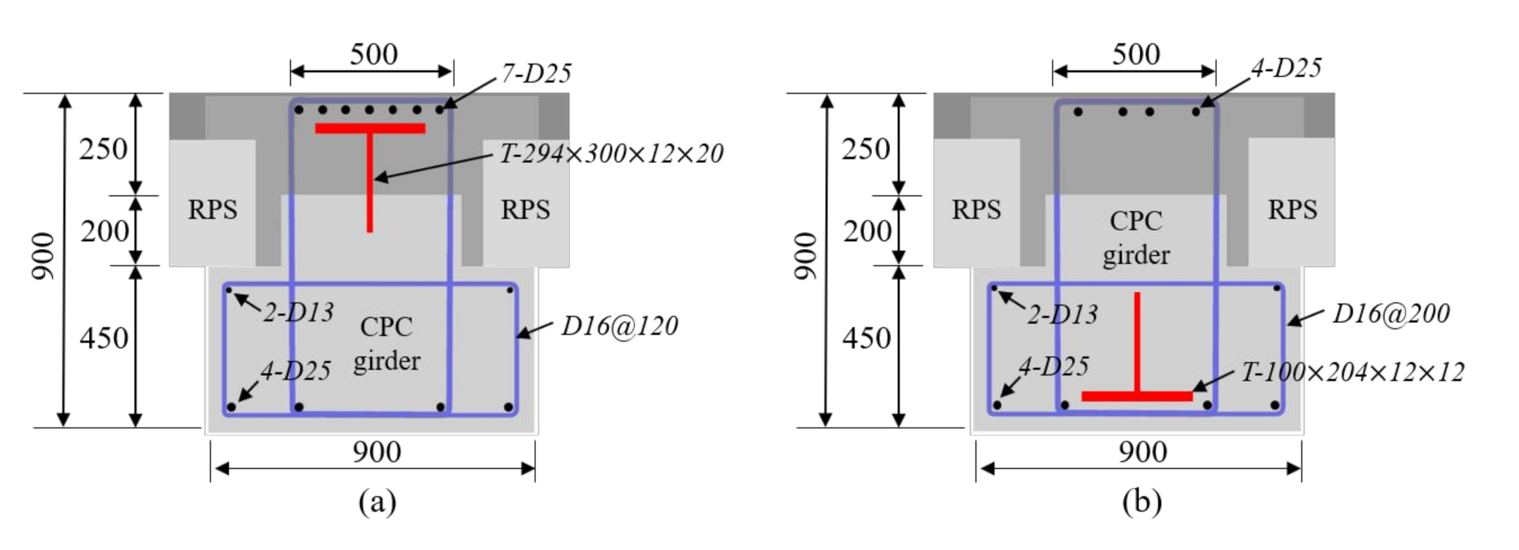
2. As shown in Figure 4, the typical girder designed with the existing PC frame in the live load conditions of this case building has a member size of 1000 × 1000 × 1100 in millimeter, and the details of rebar installed on both ends, as well as midspan of the girder, are shown in Table 3 and Figure 4, respectively. The load conditions of the girder designed with the PC frame are as follows: static load is 437.8 kN/m, fixing moment (Mu) is 4414 kN/m on both ends and 2207 kN/m on the mid-section, and concentrated load (Pu) is 2408 kN. At the structural design phase, 40 Mpa was originally used for concrete, 400 Mpa for rebar D13 and D16, and 600 Mpa for rebar D25.
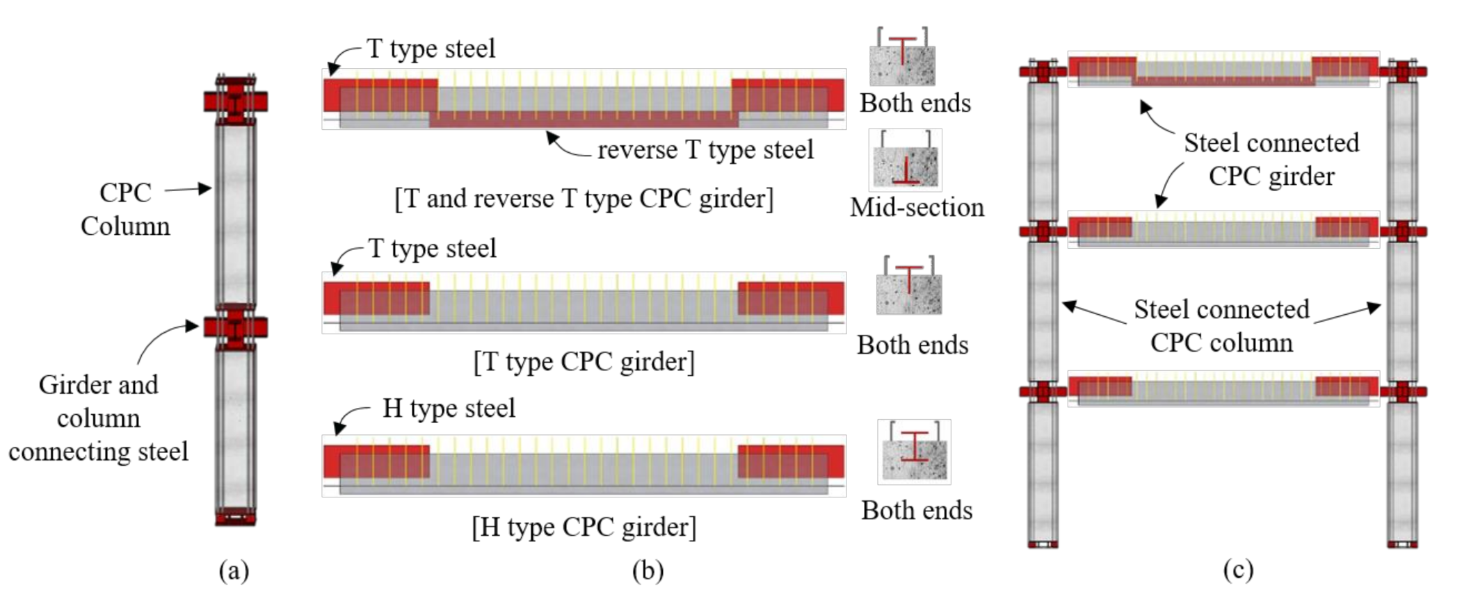
A typical girder redesigned by means of a SMART frame in the same design condition, is shown in Figure 5. The CPC girder redesigned as shown in Figure 5 comprises steel embedded on both ends and mid-section of girder and is bolt connected just like the steel structure. Therefore, in case of a steel structure like a SMART frame, the structural stability can be secured right after the assembly work is finished [19] since the moment joint method is selected based on high tensile friction bolt. The member size of steel the connected CPC girder in Figure 5 is 900 × 900 × 1100 in millimeter, and the details of steel and rebar installed on both ends and mid-section are shown in Table 3.
From the material point of view, as shown in Table 3, Figure 4 and Figure 5, the PC girders have multiple numbers of top, middle, bottom, and SS bars, 3 kinds of stirrup, and 18-∅15.2 strands at the bottom, while the CPC girders are equipped with top, bottom, and SS bars, 2 types of stirrups, and steel at the center and both ends.
In the redesign phase, we used 50 Mpa for concrete, 400 Mpa for rebar D13 and D16 and 600 Mpa for rebar D25. In addition, HSA800, a high-performance structural steel for building structure with a strength of 800 MPa, was used. The final mass product for HSA800 was developed in 2011 through studies conducted over several years by POSCO, a steel production company, and RIST (Research Institute of Industrial Science and Technology) in Korea [32], and the performance was verified through a material test [33]. If a high-strength structural steel is applied, the load can be supported even with a relatively small cross section that is inversely proportional to the strength of structural steel, leading to better constructability and maximization of space utilization [34]. It was applied to heavily loaded or long span buildings, such as Lotte World Tower and Kwanjeong Library of Seoul Nation University in Korea [35]. The high-performance structural steel of HSA800 has advantages from the structural aspect, including compactification of structural members, minimization of member sizes and self-load reduction of buildings [36]. In addition, it has various benefits, such as reduction of materials cost, as a result of the reduction of the cross section of members, securing transportation, lifting, and usable spaces [37].
As previously mentioned, for a CPC girder redesigned with the SMART frame from Figure 5, the use of a high-strength structural steel of HSA800 results in the reduction of sectional size by approximately 20% compared to the existing PC girder, and the quantity of rebar is also dramatically reduced. The quantity of construction resources for girders designed by each structural method is analyzed in detail in Section 4.3.

4.3. Quantity Estimate of Resources

As previously mentioned, after the typical PC girder of the case building is redesigned by a CPC girder, the quantity of resources, such as concrete, rebar, steel, and strand, is analyzed. As indicated in Table 4, 637 typical girders of the case project are present, which account for approximately 50% of the total 1273 girders. Typical girders are 208 on the first floor, 212 on the second floor, and 217 on the third floor, and are evenly distributed for each floor.
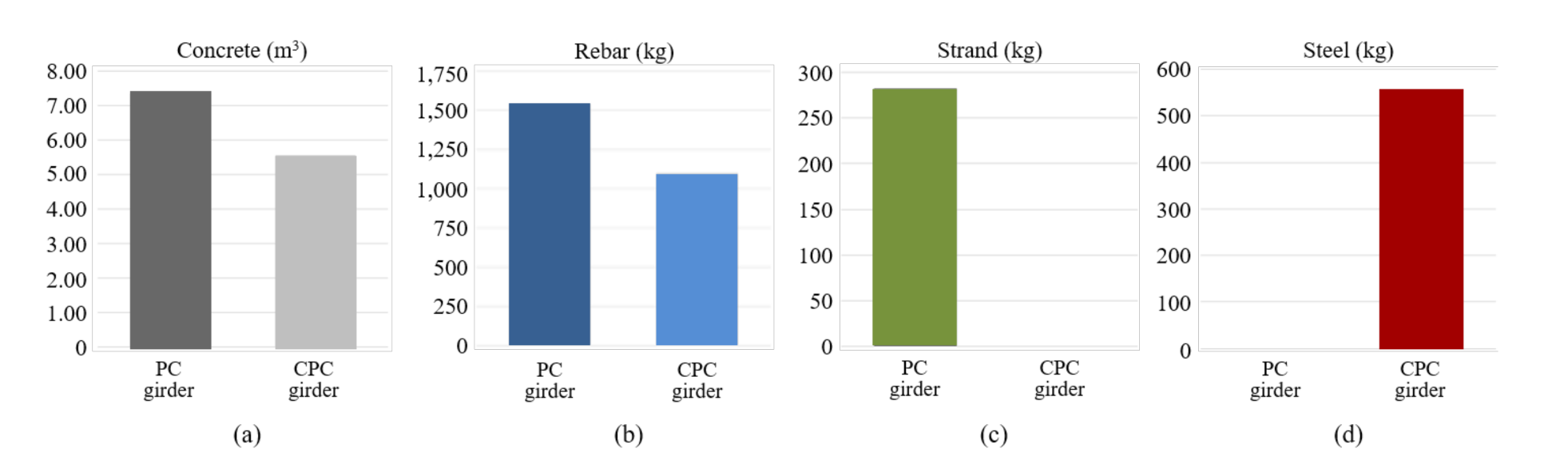
Figure 6 displays the quantity of concrete, rebar, strand, and steel used in PC and CPC girders. As shown in Figure 6, each PC girder comprises the following: 7.37 m3 of concrete, 1547.84 kg of rebar, and 282 kg of strand. The weight of steel per rebar diameter is 867.47 kg for D25, 658.48 kg for D16, and 21.89 kg for D13.
For each CPC girder, the following are used: 5.56 m3 of concrete, 1098.54 kg of rebar, and 556 kg of steel. The weight of steel per rebar diameter is 418.17 kg for D25, 658.48 kg for D16, and 21.89 kg for D13. For reference, although strand is included in the PC girder considering the characteristic of structural system, steel is included in the CPC girder of the SMART frame without strand.
If the quantities of the CPC girder are compared with those of the PC girder, we find that while each CPC girder has 1.82 m3 of concrete, 449.30 kg of rebar, and 282 kg of strand less than those of a PC girder; it has an additional 556 kg of steel. As previously explained, this result was achieved by the reduction of rebar and strand quantities due to the increase in member strength against equal loads after the use of the high-strength structural steel of HSA800.
Using the quantity of resources that are used in girders per construction method analyzed in this way, the total quantity of typical girders used in the case building is estimated, as shown in Table 5. The actual quantity of typical girders manufactured with the PC frame can be calculated as 4694.69 m3 of concrete, 533.17 ton of rebar, and 179.63 ton of strand. In addition, if the corresponding PC girder is redesigned with the SMART frame, the total quantity can be calculated as 3541.72 m3 of concrete, 276.46 ton of rebar, and 354.17 ton of steel.
As shown in Table 5, if the case building is redesigned with the SMART frame, the quantity of concrete is reduced by 1152.9 m3 (~25%), and so is that of rebar by 286.2 ton (~29%), compared to the existing PC frame. Due to the characteristic of structural system, while 354.1 ton of steel was added in the CPC girder of the SMART frame, no strand was used.
In this section, we analyze the quantity of concrete, rebar and steel used when the SMART frame is applied in the case building. The construction resources that are reduced by the innovative method not only affect the construction cost but also tremendously reduce CO2 emissions.

4.4. Cost Reduction Effects

The construction cost of PC and CPC girders is analyzed using the previously investigated resources quantity in this section. The construction cost estimation is standardized by material, labor, and equipment cost corresponding to design standard per each structural type, as explained earlier.
For material cost, the Korean price information annually provided by the Korea Price Research Center is used [38], and, for labor and equipment costs, the standard market unit price data per construction type published in the second half of 2020 is used, which is annually provided by the Ministry of Land, Infrastructure and Transport [39]. For rebar, the weighted average unit prices considering the quantities of D13, D16 and D25 are applied.
As indicated in Table 6, the construction unit prices of concrete per m3 are as follows: 75.57 USD for material cost, 8.84 USD for labor cost, and 4.35 USD for equipment cost (total: 88.76 USD/m3). The labor and equipment unit prices cover concrete forming preparation, including finish work, concrete forming, concrete compacting, and curing of concrete. The construction unit prices of rebar per ton are as follows: 537.41 USD for material cost, 354.74 USD for labor cost, and 18.67 USD for equipment cost (total: 910.83 USD/ton). The labor and equipment unit prices are estimated based on on-site processing and assembly work of rebar, and they include costs associated with cutting, processing, and assembling the rebar, as well as rent fees for machines and tools (rebar bender, etc.). The construction unit price of steel per ton is as follows: 917.73 USD for material cost, 87.49 USD for labor cost, and 1.79 USD for equipment cost (total: 1007.01 USD/ton). The labor and equipment unit prices are estimated based on costs associated with a simple installation of processed steel on CPC girder, and they include steel installation, temporary tightening, and deformation capturing. Here, machine costs, such as fuel cost for a crane, were excluded.
The construction unit prices for strand per ton are as follows: 1240.18 USD for material cost, 43.40 USD for labor cost, and 2.28 USD for equipment cost (total: 1258.86 USD/ton). The labor and equipment unit prices are calculated based on the costs associated with installing strands on PC girder and tensing work, and they include cost of tensing and machine rent fee. Table 7 shows the costs spent on PC and CPC girders, which are calculated by multiplying construction unit prices per resource in Table 6 with the quantity of resources investigated in Figure 6.
As indicated in Table 7, the amount spent on PC girders is calculated by multiplying the quantity of resources with the construction unit prices. The results of the calculation of unit prices per single resource are as follows: 654.20 USD for concrete, 1407.81 USD for rebar, and 362.61 USD for strand (total: 2426.62 USD). In addition, the amount spent on CPC girders is calculated by multiplying the quantity of resources with the construction unit prices. The results of the calculation of unit prices per single resource are as follows: 493.53 USD for concrete, 1000.58 USD for rebar, 559.90 USD for steel, and 2054.01 USD per each girder, in total.
If the amount spent on typical girders estimated by the previous method per structural system is carefully analyzed, the cost proportion is indicated, as shown in Figure 7a. In the case of CPC girders, rebar accounts for the most cost proportion at 49% (1000.58 USD), followed by steel at 27% (559.90 USD) and concrete at 24% (493.53 USD). In case of PC girders, rebar accounts for the most proportion at 58% (1,409.81 USD), followed by concrete at 27% (654.20 USD) and strand at 15% (362.61 USD).
Furthermore, the cost comparison shown in Figure 7b indicates that the concrete for PC girders costs 654.20 USD, whereas that for CPC girders costs 493.53 USD. Therefore, CPC girders cost 160.00 USD less than PC girders, resulting in a reduction effect of approximately 24.6%. This result was due to the fact that the cross section of the resource was excessively reduced, which led to the decrease in the quantity of concrete because of the redesigning of the girder with the SMART frame.
The rebar for PC girders cost 1409.81 USD, whereas that for CPC girders cost 1000.58 USD. Thus, CPC girders cost 409.23 USD less than PC girders, resulting in a reduction effect of approximately 29.03%. Such result made it possible to excessively reduce the quantity of the resource with the use of the high-strength structural steel of HSA800 by redesigning the girder with the SMART frame. In addition, the construction unit price of each resource is different for the girder types as shown in Table 6, and in particular, compared to that of other resources, the construction unit price of rebar for PC girder appears to be quite expensive; thus, large difference in cost appear. Moreover, it was confirmed that the strand only used for PC girders costs 362.61 USD, and the steel only used for CPC girders costs 559.90 USD. As a result of analyzing the resource cost for each structural system, it was found that the cost of a CPC girder decreased by 409.23 USD per piece compared to a PC girder, which means that the CPC girder of SMART frame is approximately 15.4% cheaper than the PC girder of existing PC frame.

4.5. CO2 Emission Reduction Effects

In this section, ECO2 generated by the case building is analyzed using the previously analyzed quantity of materials. ECO2 of the case building can be estimated using the basic CO2 emission unit per material quantity. The CO2 emission unit basically depends on the industrial structure of each country, and many resources are involved in the process of material production, transportation, and installation. Therefore, the CO2 emission unit for each country is generally calculated by using the input-output tables of that country. For example, many countries, including Europe [40], China [41], and Japan [42], have different CO2 emission units depending on the industrial structure of each country. In case of Korea, Hong et al. [43], Hong et al. [44], Jeong, Lee, Huh, and Lee [45], and Park et al. [46] referred to input and output tables of The Bank of Korea to define CO2 emissions per construction material based on energy consumptions throughout all construction stages from materials gathering to processing to manufacturing. Such an estimated value of the basic CO2 emissions per material quantity is the most logical method for estimating ECO2 of materials. In this study, as shown in Table 8, the CO2 emission unit of the resources input to PC and CPC girders is applied by referring to the cases of SMART frame [8,26], along with the literature introduced above.
Table 8 shows CO2 emissions per unit quantity of concrete, rebar, strand, and steel: 140.03, 3500, 4333, and 4166 kg-CO2/ton, respectively. Strand has the most CO2 emissions per unit quantity, followed by steel, rebar and concrete. As shown in Table 9, ECO2 is estimated by multiplying CO2 emissions per unit price of Table 8 with the quantities of PC and CPC girders.
As shown in Table 9, ECO2 of a single PC girder is calculated as 1032 kg-CO2 for concrete, 5418 kg-CO2 for rebar, and 1222 kg-CO2 for strand (total: 7672 kg-CO2). In addition, ECO2 of a single CPC girder is calculated as 779 kg-CO2 for concrete, 3847 kg-CO2 for rebar, and 2316 kg-CO2 for steel (total: 6942 kg-CO2).
A detailed analysis of the estimated ECO2 of the typical girder shows that, for a CPC girder, rebar accounts for the most ECO2 proportion as 55% (3847 kg-CO2), followed by steel as 33% (2316 kg-CO2) and concrete as 11% (779 kg-CO2), as shown in Figure 8a. For a PC girder, rebar accounts for the most proportion as 71% (5418 kg-CO2), followed by strand as 16% (1222 kg-CO2) and concrete as 13% (1032 kg-CO2).
Furthermore, as shown in Figure 8b, ECO2 comparison indicates that CO2 emitted from the concrete of a PC girder is 1032 kg-CO2, whereas that from the concrete of a CPC girder is 779 kg-CO2. This shows that ECO2 from a CPC girder is reduced by 253 kg-CO2 compared to that from a PC girder, which causes a reduction effect of approximately 24.51%. The reason for this is, as previously mentioned in Table 1, that the SMART frame is a moment frame while the PC frame is a pin-joint structure. Moreover, it is because HSA800 was used in the CPC girder. In the case of rebar, 5418 kg-CO2 was emitted from the PC girder, whereas 3847 kg-CO2 was emitted from the CPC girder, which showed that ECO2 from the CPC girder was reduced by 1571 kg-CO2 compared to that from the PC girder, leading to a reduction effect of approximately 29.01%. In particular, strand, which is only used in the PC girder, emits 1222 kg-CO2, while steel, which is only used in the CPC girder, emits 2316 kg-CO2. ECO2 was analyzed this way for each structural system. As a result, compared to the PC girder, the cost of a single CPC girder was reduced by 731 kg-CO2, accounting for approximately 9.52% cost reduction.
The case building is an HLS logistics building where, compared to other common buildings, a large quantity of resources is used. Table 10 shows the total ECO2 estimated by multiplying ECO2 used in a single typical girder per structural system, which is analyzed in Table 9, with the number of typical girders in the case building of Table 4.
As shown in Table 10, the case building designed as a PC frame generates 657 ton-CO2 for concrete, 3451 ton-CO2 for rebar, and 778 ton-CO2 for strand, resulting in a total of 4887 ton-CO2 of embodied carbon dioxide. When the case building is constructed with SMART frame, 496 ton-CO2 for concrete, 2450 ton-CO2 for rebar, and 1475 ton-CO2 for steel, a total 4422 ton-CO2 of ECO2 is generated. As a result, if SMART frame is applied to case building as shown in Table 10, ECO2 is reduced by 465 ton-CO2 compared to the existing PC frame. In addition, ECO2 per unit area was 2.78 kg-CO2, which was a reduction effect of about 9.52%. ECO2 per unit area is calculated by dividing the estimated ECO2 of the existing PC and SMART frames by the total floor area of the case building. Through this study, it is confirmed that a lot of ECO2 reduction is expected if the case building designed as a PC frame is replaced with a SMART frame.

5. Discussion

To accurately estimate the whole building cost, we need to redesign the structural frame of the whole building. However, it is difficult to redesign the whole building into a SMART frame due to limited time and research budget. And, as mentioned in Section 4.2, it was confirmed through preliminary research that the effect of reducing resource quantity was not large in the case of the column covering compressive force in the axial direction. Therefore, in this study, when the girder that bears the bending moment in the PC frame is changed to the CPC girder of the SMART frame, it was confirmed that the amount of reinforcement and concrete and the corresponding ECO2 reduction effect were large. Based on this fact, in this study, one of the typical PC girders, which accounts for about 50% of the total girders, was redesigned as a CPC girder. As a result, it was confirmed that the ECO2 per unit building area of the SMART frame to which the CPC girder was applied is reduced by about 9.52% compared to the PC frame, as shown in Table 10. And as shown in Table 7, it was found that the cost of typical CPC girder was reduced by about 15.4% compared to PC girder.
In the case of logistics buildings using conventional PC girders, the reinforcement quantity of girders is generally proportional to their size or concrete quantity. Therefore, by applying the ECO2 and cost reduction rate derived in this study to the quantity of girders other than typical girders, the approximate ECO2 reduction and cost saving effects for the girders of the whole building are easily calculated. If sufficient time and budget for redesign are provided, the ECO2 reduction effect for a total of 1273 girders and 942 columns can be more accurately estimated.
In addition, SMART frame is a moment frame that does not require a heavy duty shear wall as explained in Table 1. Thus, if the existing heavy building core is modified to a simple vertical passageway, a large amount of ECO2 reduction will be expected. As shown in Figure 4 and Figure 5, in the case of CPC components, the cross section is smaller than that of PC components, reducing the weight per piece, so that relatively low-capacity lifting equipment can be used. In this case, the energy use for equipment operation is reduced, and a corresponding amount of CO2 reduction effect is predicted. In the near future, further research on additional ECO2 reduction effects should be conducted for sustainable logistics building.

6. Conclusions

SMART frame is a construction method that was developed to solve the problems of the conventional PC frame. This study analyzed ECO2 reduction effects based on the reduction of input resources from the CO2 perspective when the PC frame in HLS logistic buildings was replaced with a CPC frame. For this purpose, a case building was selected and a typical girder designed with a PC frame was redesigned with a SMART frame; then, the ECO2 per structure method was compared. The following facts were confirmed:
First, if HLS buildings are designed with a PC frame, a pin-point structure just like the case project, a large quantity of resources is used to secure structural stability. However, a SMART frame has a largely reduced cross section due to its moment joint, and it was confirmed that quantities of concrete and rebar are largely reduced. For the case project, the CPC girder was compared to the PC girder, and the quantity of concrete was reduced by approximately 25.56% (1.82 m3), and the quantity of rebar was reduced by approximately 29.03% (449.30 kg).
Second, it was confirmed that if the SMART frame is applied to HLS buildings like the case building, the manufacturing cost can be reduced due to the decreased quantity of input resources. Compared to the PC girder, for the CPC girder, the cost for input resource for a single girder was reduced by 15.4% (409.23 USD). In particular, this cost reduction effect was achieved because strand was removed, and the quantity of rebar was largely reduced, while steel was added.
Third, if the SMART frame is applied to the case project, ECO2 remarkably reduced due to the decreased quantity of input resources in terms of CO2. In the case building, the existing PC girder emits 7672 kg-CO2 per girder, while the CPC girder emits 6942 kg-CO2 per girder. Compared to the PC girder, the CPC girder has a reduced amount of CO2 (730 kg-CO2, which is approximately 9.52% of that of the PC girder), and, if it is applied in all the 637 typical girders, a large quantity of ECO2 (465 ton-CO2) can be reduced. Considering the globally intensified green environment regulations, this result proves that the steel connected CPC frame (which is improved from the existing PC frame) can be applied as an alternative solution for reducing ECO2 of HLS logistics buildings.
Through this study, it was proven that a large quantity of ECO2 is reduced if a steel connected CPC frame is used in HLS logistics buildings. The result of this study can be utilized to secure structural ability, as well as realize a practical sustainable structure, that reduces the ECO2 of HLS logistics building.

Author Contributions

Conceptualization, S.K. and K.P.; methodology, S.K.; validation, S.S. and H.F.; formal analysis, S.S.; investigation, H.F.; resources, K.P.; data curation, S.K.; writing—original draft preparation, S.K.; writing—review and editing, K.P. and S.S.; visualization, S.S.; supervision, S.K.; project administration, S.K.; funding acquisition, K.P. and S.K. All authors have read and agreed to the published version of the manuscript.

Funding

This research was supported by the National Research Foundation of Korea (NRF) grant funded by the Korea government (MSIT) (No. 2018M2B2B1065635).

Institutional Review Board Statement

Not applicable.

Informed Consent Statement

Not applicable.

Data Availability Statement

Data sharing is not applicable to this article.

Acknowledgments

This research was supported by the National Research Foundation of Korea (NRF) grant funded by the Korea government (MSIT) (No. 2018M2B2B1065635).

Conflicts of Interest

The authors declare no conflict of interest.

References

  1. Pachauri, R.K.; Allen, M.R.; Barros, V.R.; Broome, J.; Cramer, W.; Christ, R.; Dubash, N.K. Climate change 2014: Synthesis report. Contribution of Working Groups I, II and III to the Fifth Assessment Report of the Intergovernmental Panel on Climate Change. 2014, p. 151. Available online: https://www.ipcc.ch/site/assets/uploads/2018/02/SYR_AR5_FINAL_full.pdf (accessed on 12 June 2020).
  2. Pacheco-Torgal, F.; Cabeza, L.F.; Labrincha, J.; De Magalhaes, A.G. Eco-Efficient Construction and Building Materials: Life Cycle Assessment (LCA), Eco-Labelling and Case Studies; Woodhead Publishing; Elsevier: Cambridge, UK, 2014; pp. 624–630. Available online: https://books.google.co.kr/books?hl=ko&lr=&id=_ZjiAgAAQBAJ&oi=fnd&pg=PP1&ots=e8l1G4maRg&sig=BNJtO3HRm5qY6nOmMwQH7-X1iU8#v=onepage&q&f=false (accessed on 21 June 2020).
  3. Lee, K.H. A study on the estimation of the amount of energy consumption and CO2 emission during building in construction stage of multifamily housing. JAIK 2000, 16, 125–132. (In Korean) [Google Scholar]
  4. Cao, C. Sustainability and life assessment of high strength natural fibre composites in construction. In Advanced High Strength Natural Fibre Composites in Construction; Woodhead Publishing: Cambridge, UK, 2017; pp. 529–544. ISBN 9780081004111. [Google Scholar]
  5. Pomponi, F.; Moncaster, A. Embodied carbon mitigation and reduction in the built environment–what does the evidence say? J. Environ. Manag. 2016, 181, 687–700. [Google Scholar] [CrossRef] [PubMed] [Green Version]
  6. De Wolf, C.; Pomponi, F.; Moncaster, A. Measuring embodied carbon dioxide equivalent of buildings: A review and critique of current industry practice. Energy Build. 2017, 140, 68–80. [Google Scholar] [CrossRef]
  7. Son, S.; Lim, J.; Oh, O.; Kim, J.T.; Kim, S. Risk Identification of Innovative Composite Precast Concrete Structure Applied to Heavy-Loaded-and Long-Span Buildings, Proceedings of the the Global Civil Engineering of the Conference; Springer: Singapore, 2017; pp. 291–296. Available online: https://link.springer.com/chapter/10.1007/978-981-10-8016-6_23 (accessed on 21 May 2020). (In Korean)
  8. Lee, D.; Lim, C.; Kim, S. CO2 emission reduction effects of an innovative composite precast concrete structure applied to heavy loaded and long span buildings. Energy Build. 2016, 126, 36–43. [Google Scholar] [CrossRef]
  9. Lim, C.Y.; Joo, J.K.; Lee, G.J.; Kim, S.K. In-situ production analysis of composite precast concrete members of green frame. JKIBC 2011, 11, 501–514. [Google Scholar] [CrossRef]
  10. Hong, W.K.; Kim, J.M.; Park, S.C.; Kim, S.I.; Lee, S.G.; Lee, H.C.; Yoon, K.J. Composite beam composed of steel and pre-cast concrete. (Modularized Hybrid System, MHS) Part II: Analytical investigation. Struct. Des. Tall Spec. Build. 2009, 18, 891–905. [Google Scholar] [CrossRef]
  11. Hong, W.K.; Park, S.C.; Lee, H.C.; Kim, J.M.; Kim, S.I.; Lee, S.G.; Yoon, K.J. Composite beam composed of steel and precast concrete (modularized hybrid system). Part III: Application for a 19-storey building. Struct. Des. Tall Spec. Build. 2010, 19, 679–706. [Google Scholar] [CrossRef]
  12. Kim, S.; Hong, W.K.; Kim, J.H.; Kim, J.T. The development of modularized construction of enhanced precast composite structural systems (Smart Green frame) and its embedded energy efficiency. Energy Build. 2013, 66, 16–21. [Google Scholar] [CrossRef]
  13. Hong, W.K.; Kim, G.; Lim, C.; Kim, S. Development of a steel-guide connection method for composite precast concrete components. J. Constr. Eng. Manag. 2017, 23, 59–66. [Google Scholar] [CrossRef]
  14. Lee, S.H.; Kim, S.E.; Kim, G.H.; Joo, J.K.; Kim, S.K. Analysis of structural work scheduling of green frame-focusing on apartment buildings. JKIBC 2011, 11, 301–309. [Google Scholar]
  15. Ghayeb, H.H.; Razak, H.A.; Sulong, N.R. Evaluation of the CO2 emissions of an innovative composite precast concrete structure building frame. J. Clean. Prod. 2020, 242, 118567. [Google Scholar] [CrossRef]
  16. Choi, S.W.; Oh, B.K.; Park, J.S.; Park, H.S. Sustainable design model to reduce environmental impact of building construction with composite structures. J. Clean. Prod. 2016, 137, 823–832. [Google Scholar] [CrossRef]
  17. Park, S.C.; Hong, W.K.; Kim, J.T. Application of Smart Frames to tall buildings with dual systems and with building frame systems. Indoor Built Environ. 2014, 23, 161–170. [Google Scholar] [CrossRef]
  18. Hong, W.K.; Yune, D.Y.; Park, S.C.; Yoon, T.H. An assessment of the energy and resource-efficient hybrid composite beams for multi-residential apartments. Indoor Built Environ. 2011, 20, 148–155. [Google Scholar] [CrossRef]
  19. Ko, H.J.; Hong, W.K.; Park, S.C.; Lim, G.T.; Kim, J.H.; Kim, J.T. Reduction effect of toxic substances for apartment buildings with an ecofriendly pre-cast composite structural system. Indoor Built Environ. 2013, 22, 110–116. [Google Scholar] [CrossRef]
  20. Lim, J.; Kim, S. Evaluation of CO2 emission reduction effect using in-situ production of precast concrete components. JAABE 2020, 19, 176–186. [Google Scholar] [CrossRef] [Green Version]
  21. Son, S.; Lim, J.; Do Yeong, K.; Oh, Y.K.; Kim, S. Erection Simulation of Steel Connected Precast Concrete Components for Logistics Buildings. In Proceedings of the 3rd World Congress on Civil, Structural, and Environmental Engineering (CSEE’18), Budapest, Hungary, 8–10 April 2018. Paper No. ICSENM 118 1-8. [Google Scholar]
  22. Lee, S.; Hong, W.K.; Lim, C.; Kim, S. A dynamic erection simulation model of column-beam structures using composite precast concrete components. J. Intell. Robot Syst. 2015, 79, 537–547. [Google Scholar] [CrossRef]
  23. Hong, W.K.; Kim, S.I.; Park, S.C.; Kim, J.M.; Lee, S.G.; Yoon, K.J.; Kim, S.K. Composite beam composed of steel and precast concrete (modularized hybrid system). Part IV: Application for multi-residential housing. Struct. Des. Tall Spec. Build. 2010, 19, 707–727. [Google Scholar] [CrossRef]
  24. Kim, S.H.; Lee, W.S.; Kim, S.K.; Lee, D.H. Development of form to improve the productivity of PC structure connections-focused on apartment buildings. JKIBC 2010, 10, 11–20. [Google Scholar]
  25. Hong, W.K.; Lee, G.; Lee, S.; Kim, S. Algorithms for in-situ production layout of composite precast concrete members. Autom. Constr. 2014, 41, 50–59. [Google Scholar] [CrossRef]
  26. Lim, C.; Lee, S.; Kim, S. Embodied energy and CO2 emission reduction of a column-beam structure with enhanced composite precast concrete members. JAABE 2015, 14, 593–600. [Google Scholar]
  27. Hong, W.K.; Lim, G.T.; Park, S.C.; Kim, J.T. Energy efficiencies of linear-shaped multi-residential apartment buildings built with hybrid structural systems. Energy Build. 2012, 46, 30–36. [Google Scholar] [CrossRef]
  28. Kim, S.; Hong, W.K.; Ko, H.J.; Kim, J.T. The energy efficient expansion remodeling construction method of bearing wall apartment buildings with pre-cast composite structural systems. Energy Build. 2013, 66, 714–723. [Google Scholar] [CrossRef]
  29. Lee, S.H.; Park, J.Y.; Lim, C.Y.; Kim, S.K. Constructability analysis of green columns at the low bending moment zone. JCEPM 2013, 3, 12–19. [Google Scholar] [CrossRef] [Green Version]
  30. Hong, W.K.; Kim, S.K.; Kim, H.G.; Yoon, T.H.; Yune, D.Y.; Kim, S.I. A feasibility study of Green Frame (GF) for the implementation of low-carbon emissions & long-life housing. JKIBC 2010, 10, 57–63. [Google Scholar]
  31. Lee, S.; Joo, J.; Kim, J.T.; Kim, S. An analysis of the CO2 reduction effect of a column-beam structure using composite precast concrete members. Indoor Built Environ. 2012, 21, 150–162. [Google Scholar] [CrossRef]
  32. Kim, D.H.; Lee, S.E.; Chung, K.S.; Kim, J.H. Features and Super-tall Building Applications of HSA800 Steel Plates for Building Structures. Mag. Korean Struct. Eng. Assoc. 2013, 20, 41–47. [Google Scholar]
  33. Lee, C.H.; Kim, D.K.; Han, K.H.; Park, C.H.; Kim, J.H.; Lee, S.E.; Kim, D.H. Tensile testing of groove welded joints joining thick-HSA800 plates. Int. J. Concr. Struct. Mater. 2013, 25, 431–440. [Google Scholar] [CrossRef]
  34. Lee, K.; Lee, M.J.; Oh, Y.S.; Kim, T.S.; Kim, D.H. Local buckling behavior of stub H-shaped columns fabricated with HSA800 high performance steels under concentric axial loading. Int. J. Concr. Struct. Mater. 2013, 25, 289–297. [Google Scholar]
  35. Yoo, J.H.; Kim, J.W.; Yang, J.G.; Kang, J.W.; Lee, D.W. Evaluation on applicability of built-up square tubular compression members fabricated with HSA800 high performance steel considering local buckling. KSSC 2013, 25, 223–231. [Google Scholar] [CrossRef]
  36. Kim, T.S.; Lee, M.J.; Oh, Y.S.; Lee, K.M.; Kim, D.H. A study on compressive strength of built-up H shaped columns fabricated with HSA800 high performance steels. Int. J. Concr. Struct. Mater. 2012, 24, 627–636. [Google Scholar]
  37. Cho, S.H.; Kim, D.H.; Kim, J.W.; Lee, S.E.; Kim, J.H. Alternative design of mega structural members of a super-tall building using 800MPa grade high-performance steel plate. Int. J. Concr. Struct. Mater. 2014, 26, 299–309. [Google Scholar] [CrossRef]
  38. Korea Price Information. Available online: https://www.kpi.or.kr/www/price/category.asp?CATE_CD=1020 (accessed on 24 June 2020). (In Korean).
  39. Ministry of Land, Infrastructure, and Transport. Available online: https://www.codil.or.kr/helpdesk/read.do;jsessionid=1yfTIuke2UuJ8SZQYX6TgjGcKlQUjkX6HMznlECqhaWUpdD14vnPRsMuuSIizfoS.codil_servlet_engine1?bbsId=BBSMSTR_900000000204&nttId=12176&searchWrd= (accessed on 25 June 2020). (In Korean)
  40. Pomponi, F.; Moncaster, A. Scrutinising embodied carbon in buildings: The next performance gap made manifest. Renew. Sustain. Energy Rev. 2018, 81, 2431–2442. [Google Scholar] [CrossRef] [Green Version]
  41. Zhang, X.; Wang, F. Analysis of embodied carbon in the building life cycle considering the temporal perspectives of emissions: A case study in China. Energy Build. 2017, 155, 404–413. [Google Scholar] [CrossRef]
  42. Nishimura, K.; Hondo, H.; Uchiyama, Y. Estimating the embodied carbon emissions from the material content. Energy Convers. Manag. 1997, 38, S589–S594. [Google Scholar] [CrossRef]
  43. Hong, W.K.; Park, S.C.; Kim, J.M.; Kim, S.I.; Lee, S.G.; Yune, D.Y.; Ryoo, B.Y. Development of structural composite hybrid systems and their application with regard to the reduction of CO2 emissions. Indoor Built Environ. 2010, 19, 151–162. [Google Scholar] [CrossRef]
  44. Hong, W.K.; Kim, J.M.; Park, S.C.; Lee, S.G.; Kim, S.I.; Yoon, K.J.; Kim, J.T. A new apartment construction technology with effective CO2 emission reduction capabilities. Energy 2010, 35, 2639–2646. [Google Scholar] [CrossRef]
  45. Jeong, Y.S.; Lee, S.E.; Huh, J.H. Estimation of CO2 emission of apartment buildings due to major construction materials in the Republic of Korea. Energy Build. 2012, 49, 437–442. [Google Scholar] [CrossRef]
  46. Park, H.S.; Lee, H.; Kim, Y.; Hong, T.; Choi, S.W. Evaluation of the influence of design factors on the CO2 emissions and costs of reinforced concrete columns. Energy Build. 2014, 82, 378–384. [Google Scholar] [CrossRef]
Figure 1. Overview of the SMART (Sustainable, Measurable, Attainable, Reliable, and Timely) frame: (a) Steel connected composite precast concrete (CPC) column; (b) CPC girders; (c) typical SMART frame with three types of girder.
Sustainability 13 01060 g001
Figure 2. Methodology.
Sustainability 13 01060 g002
Figure 3. Construction process of the precast concrete (PC) frame: (a) PC girder installation; (b) rib-plus precast concrete slab (RPS) installation; (c) slab and girder rebar placement; (d) concrete casting.
Sustainability 13 01060 g003
Figure 4. Section design for typical PC girder: (a) Detail at both ends; (b) detail at mid-section.
Sustainability 13 01060 g004
Figure 5. Section design for CPC girder: (a) Detail at both ends; (b) detail at mid-section.
Sustainability 13 01060 g005
Figure 6. Quantity of resources for each PC and CPC girder: (a) Concrete; (b) rebar; (c) strand; (d) steel.
Sustainability 13 01060 g006
Figure 7. Cost proportion and comparison of a typical girder: (a) Cost proportion; (b) cost comparison.
Sustainability 13 01060 g007
Figure 8. ECO2 proportion and comparison of a typical girder: (a) ECO2 proportion; (b) ECO2 comparison.
Sustainability 13 01060 g008
Table 1. Features of SMART frame [21].
DescriptionSMART FramePC Frame
1. ComponentSteel connected CPCPC
2. Structural jointMoment jointPin joint
3. Resistance to lateral forceStructural frame itselfHeavy RC shear walls and/or cores, braces
4. Role of coresSimple vertical passagewayShear wall resisting to lateral force
5. Critical pathCPC erectionMainly RC core wall
Table 2. Brief description of case building.
ItemDescription
LocationCheonan-si, South Korea
UsageLogistics building
Lot area53,056 m2
Total floor area167,614 m2
Building area42,405 m2
No. of floors4 stories (10 m floor height)
StructurePC Columns and girders, RPS with topping concrete
No. of PCColumns: 942 units, Girders: 1273 units, RPS: 3985 units
RemarksTypical girder span: 12 m long, Longest span: 24 m long, Load condition: 2.4 ton/m2
Table 3. Rebar detail on a PC girder of case building.
DescriptionReinforcementBoth EndsMid-Section
PC girderTop bar18-D254-D25
Middle bar4-D254-D25
Bottom bar4-D254-D25
Strand18-Ø15.218-Ø15.2
StirrupD16@120D16@200
Stirrup setting bar 2-D132-D13
CPC girderTop bar7-D254-D25
SteelT-294 × 300 × 12 × 20T-100 × 204 × 12 × 12
Bottom bar4-D254-D25
StirrupD16@120D16@200
Stirrup setting bar2-D132-D13
Table 4. Number of typical girders.
FloorNumber of GirdersTypical Girder Ratio (%)
Non-Typical GirderTypical GirderSum
F121020841849.8
F221121242350.1
F321521743250.2
F4Designed by steel girders
Total636637127350.0
Table 5. Quantity analysis of total typical PC and CPC girders.
FloorConcrete (m3)Rebar (ton)Strand (ton)Steel (ton)
PC (A)CPC (B)Diff. (B-A)PC (A)CPC (B)Diff. (B-A)PC (A)CPC (B)Diff. (B-A)PC (A)CPC (B)Diff. (B-A)
F11532.91156.4−376.4322.0228.5−93.558.6-−58.6-115.6115.6
F21562.41178.7−383.7328.1232.9−95.359.7-−59.7-117.8117.8
F31599.21206.5−392.7335.9238.4−97.561.1-−61.1-120.6120.6
F4------------
Total4694.63541.7−1152.9986.0699.8−286.2179.6-−179.6-354.1354.1
Table 6. Unit price analysis of resources.
DescriptionU/P (USD)Sum
MaterialLaborEquipment
Concrete (m3)75.578.844.3588.76
Rebar (ton)537.41354.7418.67910.83
Steel (ton)917.7387.491.791007.01
Strand (ton)1240.1843.402.281285.86
Note: Exchange rate is 1209.50 Won/USD as of 21 June 2020 (Bank of Korea).
Table 7. Cost analysis of a typical girder.
DescriptionPCCPCRemarks
Q’tyU/P (USD)Amount (USD)Q’tyU/P (USD)Amount (USD)
Concrete (m3)7.3788.76654.205.5688.76493.5324.6% reduction
Rebar (ton)1.548910.831409.811.099910.831000.5829.0% reduction
Steel (ton)-1007.01-0.5561007.01559.90
Strand (ton)0.2821285.86362.61-1285.86-
Total--2426.62--2054.0115.4% reduction
Note: Exchange rate is 1209.50 Won/USD as of 21 June 2020 (Bank of Korea).
Table 8. CO2 emission unit of material.
ItemContentsCO2 emission per unit
ConcreteReady-mixed concrete140.03 kg-CO2/m3
RebarHigh strength reinforcement bar3500 kg-CO2/ton
StrandPrestressed steel wire4333 kg-CO2/ton
SteelStructural steel4166 kg-CO2/ton
Table 9. Embodied CO2 (ECO2) analysis of a typical girder.
ItemECO2 (kg-CO2)Remarks
PC Girder (A)CPC Girder (B)Diff. (C = B − A)
Concrete1032779−25324.51% reduction
Rebar54183847−157129.01% reduction
Strand1222-−1222
Steel-23162316
Total76726942−7309.52% reduction
Table 10. ECO2 reduction effects for the case building.
ItemECO2 (ton-CO2)ECO2 per Unit Area (kg-CO2/m2)Remarks
PC FrameSMART FramePC FrameSMART Frame
Concrete6574963.922.9624.51% reduction
Rebar3451245020.5914.6229.01% reduction
Strand778-4.64-
Steel-1475-8.80
Total4887442229.1626.382.78 kg-CO2/m2 (9.52%) reduction
Publisher’s Note: MDPI stays neutral with regard to jurisdictional claims in published maps and institutional affiliations.

