Article

Grid-Connected Inverter for a PV-Powered Electric Vehicle Charging Station to Enhance the Stability of a Microgrid

1
Department of Electrical Engineering, Hanyang University, Seoul 04763, Korea
2
Department of Electrical & Electronic Engineering, Yonam Institute of Technology, Jinju 52821, Korea
*
Author to whom correspondence should be addressed.
Sustainability 2021, 13(24), 14022; https://doi.org/10.3390/su132414022
Submission received: 3 November 2021 / Revised: 13 December 2021 / Accepted: 14 December 2021 / Published: 19 December 2021

Abstract

:
This study proposes a grid-connected inverter for photovoltaic (PV)-powered electric vehicle (EV) charging stations. The significant function of the proposed inverter is to enhance the stability of a microgrid. The proposed inverter can stabilize its grid voltage and frequency by supplying or absorbing active or reactive power to or from a microgrid using EVs and PV generation. Moreover, the proposed inverter can automatically detect an abnormal condition of the grid, such as a blackout, and operate in the islanding mode, which can provide continuous power to local loads using EV vehicle-to-grid service and PV generation. These inverter functions can satisfy the requirements of the grid codes, such as IEEE Standard 1547–2018 and UL 1741 SA. In addition, the proposed inverter can not only enhance the microgrid stability but also charge EVs in an appropriate mode according to the condition of the PV array and EVs. The proposed inverter was verified through experimental results with four scenarios in a lab-scale testbed. These four scenarios include grid normal conditions, grid voltage fluctuations, grid frequency fluctuations, and a power blackout. The experimental results demonstrated that the proposed inverter could enhance the microgrid stability against grid abnormal conditions, fluctuations of grid frequency and voltage, and charge EVs in an appropriate mode.

1. Introduction

Recently, renewable energy sources (RES), such as photovoltaic (PV) and wind turbine generation (WTG), have been increasing in the grid to replace conventional synchronous generators [1]. These RESs are connected to the grid through power converters such as grid-connected inverters, which can weaken the microgrid by reducing the inertia of the grid [2]. Because the weak grid has low inertia, it is difficult to cope with the grid voltage and frequency fluctuations, leading to a deterioration of grid stability and power quality [3,4,5,6]. Various grid codes, such as IEEE Standard 1547–2018 and UL 1741 SA, were established to solve these problems [7,8]. These grid codes are guidelines for grid-connected inverters to maintain grid stability. According to the IEEE Standard 1547–2018 requirements, grid-connected inverters should be able to maintain grid stability and power quality by regulating the grid voltage and frequency through absorbing and supplying active or reactive power to the grid. Moreover, the grid-connected inverter should be able to detect abnormal conditions, such as a grid blackout, and operate in the islanding mode.
In addition to the increase in RESs, the penetration rate of electric vehicles (EVs) has increased to replace conventional fossil fuel vehicles. Therefore, the EV charging stations within the microgrid have also been increasing, as shown in Figure 1 [9,10,11]. Depending on the applications, each source and load can be connected to the microgrid through single or multi-stage power converters [12,13,14]. If many EVs are charged simultaneously from the microgrid, a power imbalance in the supply and demand may occur in the microgrid [15,16,17,18]. This makes the microgrid weak, decreasing its stability [19]. Unstable voltage and frequency in the microgrid can affect the power quality for charging EVs and may reduce the lifetime of an EV battery. To enhance the stability of the microgrid connected with an EV charging station, many studies [20,21,22,23,24] integrating PV generation and a charging station to the microgrid have been conducted. In [20,21,22], the optimized operation of grid-connected PV-based EV charging stations was studied. However, these studies mainly analyzed the economic improvement of the operation of PV-powered EV charging stations. In [23], it was proved that the grid stability could be improved through the total harmonic distortion (THD) of voltages using PV-powered EV charging stations. Moreover, researchers [24] studied that grid stabilization, including power gap balancing, peak shaving, valley filling of generated power, and voltage sag compensation, can be enhanced by utilizing PV-connected EV charging stations.
Researchers [25,26] have also studied improving the microgrid stability in an EV charging station by using a vehicle-to-grid service (V2G). A V2G is defined as providing power and other necessary support from an EV to the grid [27,28,29,30]. Other researchers [25] proved that EV charging stations could be used to compensate for instantaneous grid voltage fluctuations and improve the power quality. In [26], a new control method was proposed to compensate for the grid frequency by utilizing the EV charging station. These studies proved that the deterioration of the grid stability could be mitigated using a V2G. Nevertheless, these studies have not considered the compensation of voltage and frequency fluctuations simultaneously. These studies are not enough to satisfy the requirements of the grid codes, such as IEEE Standard 15247–2018 and UL 1741 SA. These studies have also not considered an islanding mode for abnormal conditions of the grid, such as a blackout.
This study proposes a grid-connected inverter for PV-powered EV charging stations, enhancing microgrid stability using a V2G and PV generation. When the microgrid voltage and frequency fluctuate, the proposed inverter can stabilize the microgrid voltage and frequency by supplying active or reactive power to the microgrid or absorbing it from the microgrid. Moreover, the proposed inverter can automatically detect abnormal conditions of the microgrid, such as a blackout, and operate in the islanding mode.
When the proposed inverter operates in the islanding mode, it is also possible to continuously supply power to local loads. In addition, the proposed inverter can not only enhance the stability of the microgrid but also charge EVs in the appropriate mode according to the conditions of EVs and PV generation. The superiority of the proposed inverter was verified and analyzed through experiments in a lab-scale testbed to mimic the operation of a PV-powered EV charging station in a microgrid. The main contributions of this study can be summarized as follows:
(1)
The proposed inverter can stabilize the microgrid voltage and frequency by supplying active or reactive power to the microgrid or absorbing it from the microgrid by using V2G and PV generation. These proposed inverter functions can satisfy the requirements of the grid codes, such as IEEE Standard 1547–2018 and UL 1741 SA.
(2)
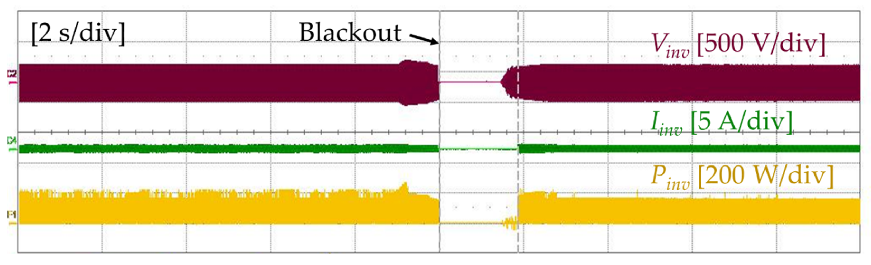
The proposed inverter can automatically detect abnormal conditions of the microgrid, such as a blackout, and operate in the islanding mode. At this time, it can provide continuous power to local loads by using V2G and PV generation.
This paper is organized into the following five sections: Section 2 describes the configuration of the PV-powered EV charging station. Section 3 introduces the control method for the proposed inverter to improve microgrid stability. Section 4 presents the experimental setup and results for validating the proposed inverter control method. Finally, the conclusions are summarized in Section 5.

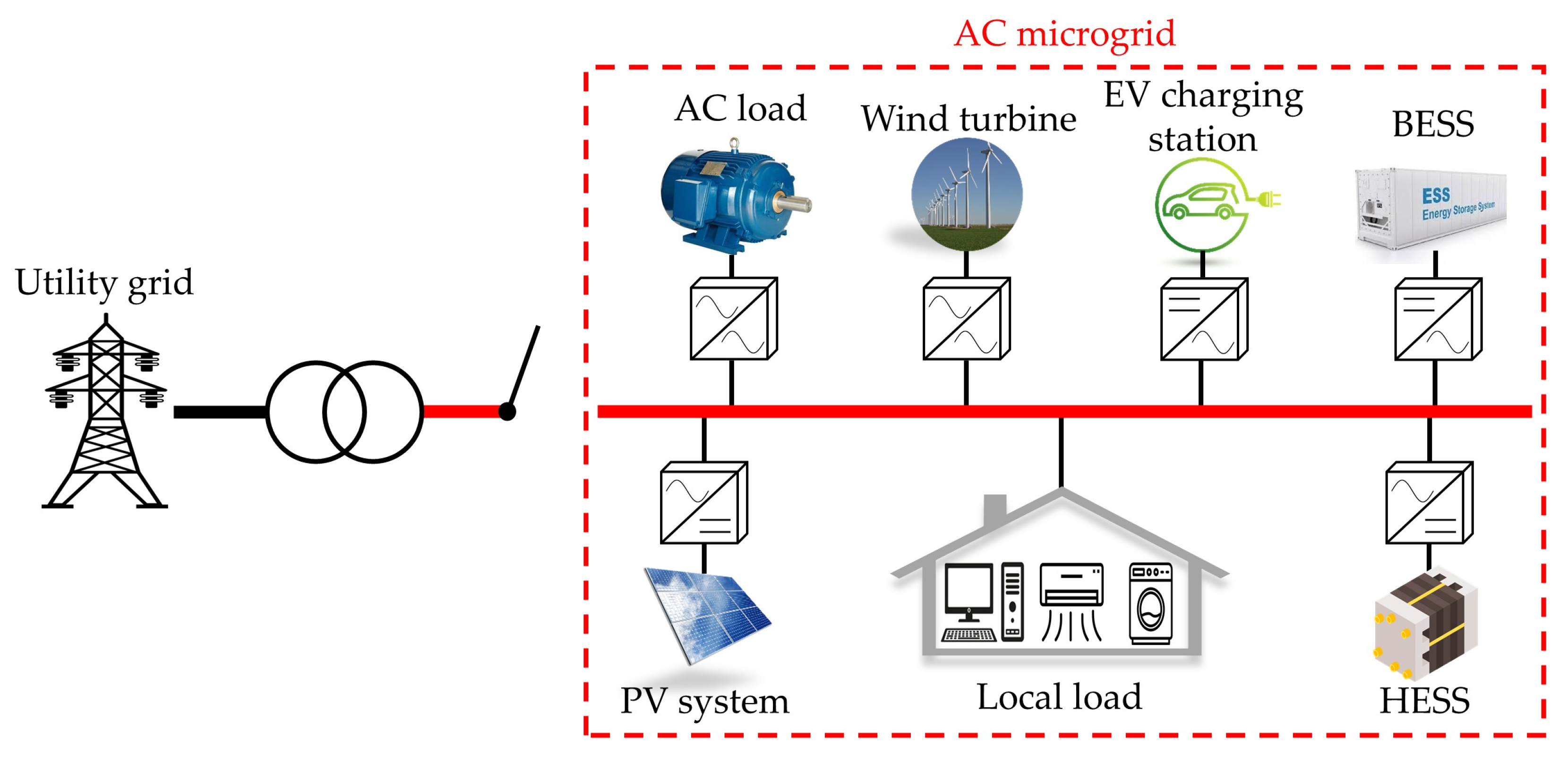
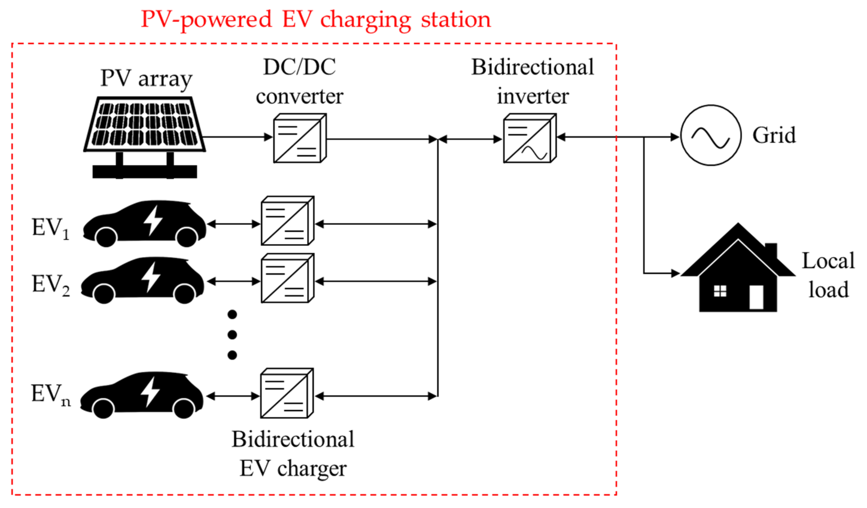
2. PV-Powered EV Charging Station Description

A PV-powered EV charging station charges EVs using PV generation as another available power source, which can reduce carbon emissions from fossil-fueled power plants. In other words, EVs can be charged using PV generation when the grid cannot supply power. It can also reduce the peak load or improve the microgrid stability by using PV generation and V2G [31]. However, EVs differ from an energy storage system because of their mobility characteristics. For example, a V2G may not be performed if there are not enough available EVs in the charging station, although a V2G is required to reduce the peak power demand or improve the stability of the microgrid. Therefore, it is crucial to consider these characteristics of a PV-powered EV charging station to use it as a stability enhancement method for the microgrid.
Figure 2 shows the configuration of the PV-powered EV charging station [32]. The PV-powered EV charging station consists of PV arrays, DC/DC converters, EVs, bidirectional EV chargers, and bidirectional inverters. The charging station is connected to the microgrid through the bidirectional inverter. The bidirectional inverter controls power flow between the charging station and the grid. The local load is connected in parallel between the bidirectional inverter and the microgrid. The PV array generates power for charging EVs or supplying the grid and local loads. A DC/DC converter is used to harvest maximum power from a PV array by performing maximum power point tracking (MPPT). The bidirectional EV charger is used to control the charge and discharge of EVs. The bidirectional inverter and the bidirectional EV charger enable a V2G between EVs and the microgrid.

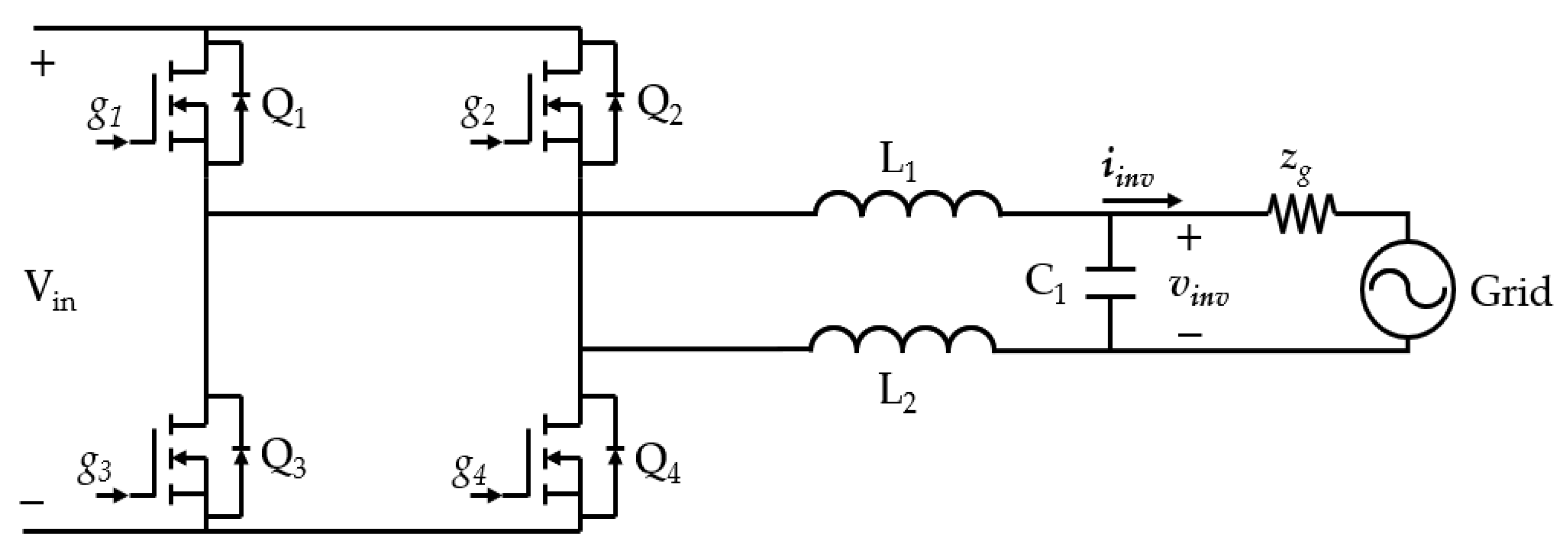
3. The Proposed Grid-Connected Inverter

Figure 3 shows the operational strategy flowchart of the proposed grid-connected inverter. The significant function of the proposed inverter is to enhance the microgrid stability. In this study, the microgrid stability is defined as the grid voltage stability, the grid frequency stability, and the grid stability from grid abnormal conditions. In addition, the microgrid in this study is considered a weak grid, because it is usually connected with various renewable energy sources (RES) and loads. In a weak grid, the grid voltage can be regulated by active power, and the grid frequency can be controlled by reactive power. Therefore, when the microgrid voltage fluctuations occur, the proposed inverter can stabilize the microgrid voltage by supplying or absorbing active power to the microgrid by using V2G and PV generation. In addition, when the microgrid frequency varies, the proposed inverter can also stabilize the microgrid frequency by supplying or absorbing reactive power to the microgrid.
The grid abnormal conditions considered in this study are grid blackout events, which can be judged through an islanding detection condition. The islanding detection condition occurs when power in the microgrid is totally cut off from the utility grid. Therefore, when power is absolutely cut off from the utility grid, the proposed inverter can stabilize the microgrid by operating in the islanding mode and continuously providing power to the local loads using V2G and PV generation. The islanding detection condition in the microgrid is distinguished from other events such as temporary faults because it occurs only when power is completely cut off from the utility grid. The islanding detection condition can be varied by the grid codes such as IEEE Standard 1547–2018 and UL 1741 SA.
According to the proposed operational strategy, the proposed inverter determines the appropriate mode for charging EVs according to EVs and PV generation conditions. The operation modes according to the operational strategy are shown in Figure 4. In Figure 4, red arrows represent the direction of power flow among the PV array, EVs, and the grid. For example, the bidirectional inverter in Figure 4b can achieve bidirectional power flow, which is caused by the voltage and frequency compensation modes. First, the proposed inverter begins receiving data from the grid, EVs, and the PV array. Then, the inverter detects whether EVs are available in the EV charging station to enhance microgrid stability. If EVs are not available, the inverter operates in mode one. In mode one, the inverter supplies the power generated from the PV array to the grid and the local load, as shown in Figure 4c. If EVs are available, the inverter judges whether the islanding detection condition occurs in the microgrid. If the islanding detection condition exists, the inverter is disconnected from the grid and operates in the islanding mode, as shown in Figure 4a. At this time, the inverter can provide continuous power to local loads using EVs and the PV array in the islanding mode.
If the islanding detection condition is not occurring in the microgrid, the proposed inverter is connected to the grid and operates in the grid-connected mode. In the grid-connected mode, the inverter detects the voltage and frequency of the microgrid. At this time, if the grid voltage or frequency fluctuation exists, the inverter operates in the voltage compensation mode or the frequency compensation mode, as shown in Figure 4b. In these modes, the inverter stabilizes the microgrid voltage and frequency using a V2G and PV generation. If the grid voltage fluctuation exists, the proposed inverter operates in the voltage compensation mode for reducing the grid voltage fluctuation. On the other hand, if the grid voltage fluctuation does not exist, the proposed inverter detects the grid frequency condition. If the grid frequency fluctuation exists, the proposed inverter operates in the frequency compensation mode for reducing the grid frequency fluctuation. If the grid voltage or frequency fluctuation does not exist in the grid-connected mode, the proposed inverter monitors the condition of EVs and the PV array for charging EVs in the appropriate mode. The proposed inverter detects whether EVs need charging and whether a PV array generates power. If EVs need charging and a PV array does not generate power, the proposed inverter operates in mode two, as shown in Figure 4d. In mode two, EVs are charged only from the grid. If EVs need charging and a PV array generates power, the proposed inverter detects whether the energy of the PV array (EPV) is greater than the energy required for charging EVs (EEV). If EPV is greater than EEV, the inverter operates in mode three, as shown in Figure 4e. In mode three, EVs are charged only from the PV array, and the proposed inverter supplies the surplus EPV to the grid. If EPV is less than EEV, the proposed inverter operates in mode four, as shown in Figure 4f. In mode four, EVs are charged from the PV array and the grid. If EVs do not need charging, the proposed inverter operates in mode one.

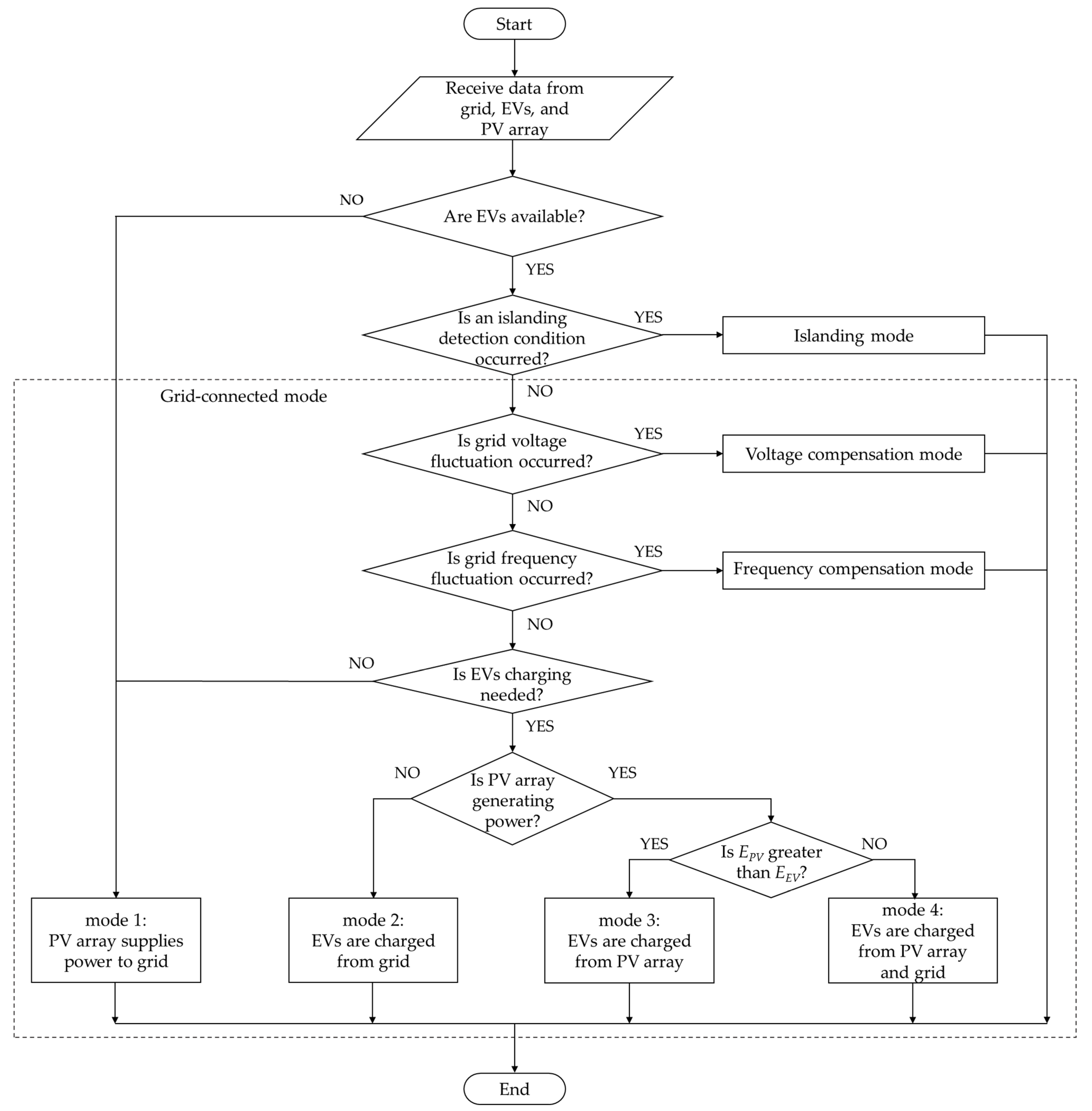
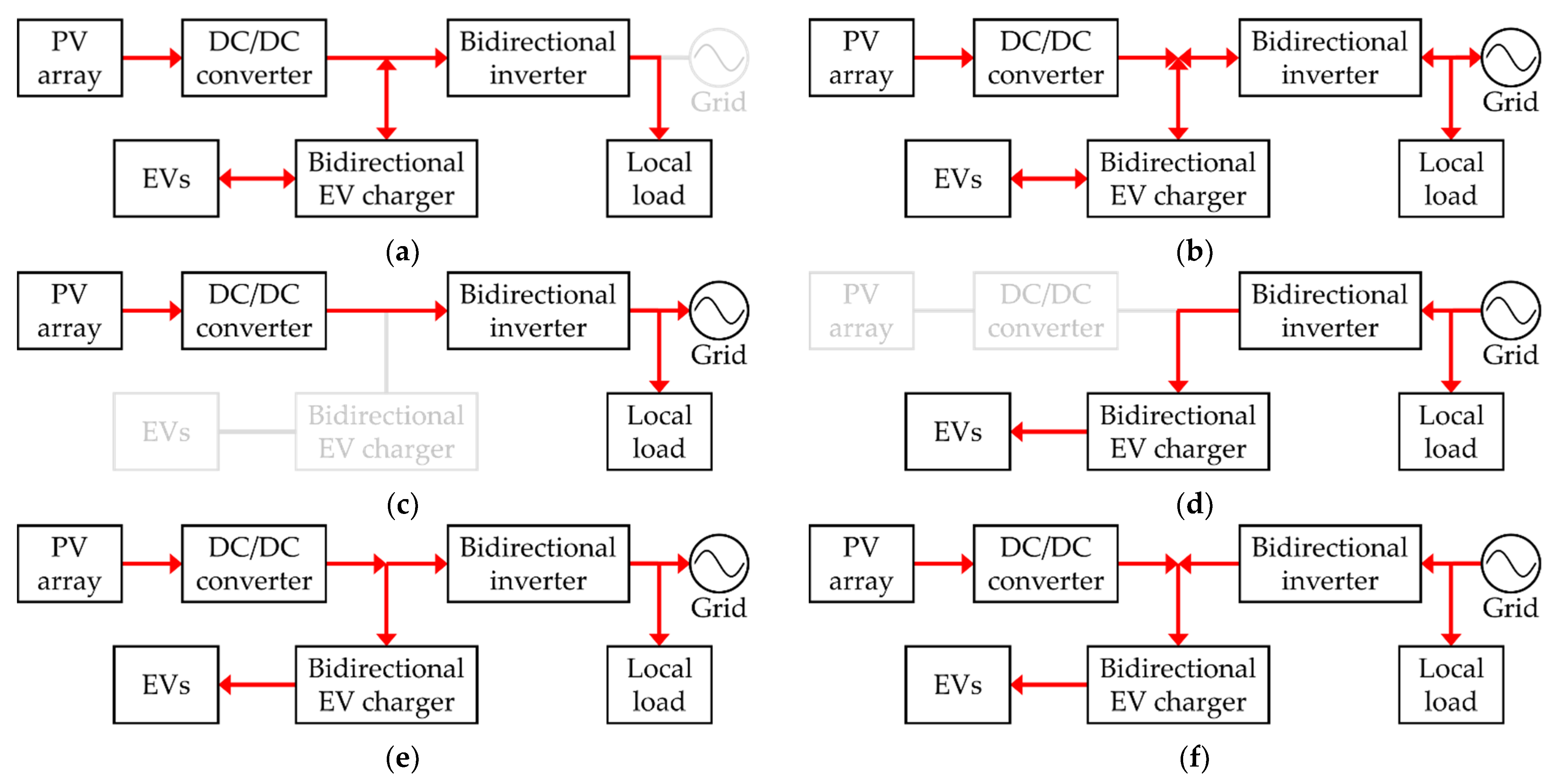
3.1. Grid-Connected Mode

The proposed inverter generally operates in the grid-connected mode because the islanding detection condition does not often occur. Thus, to realize the operating strategy of the proposed inverter in the grid-connected mode, the following three control schemes are introduced: main control scheme, voltage compensation control scheme, and frequency compensation control scheme.

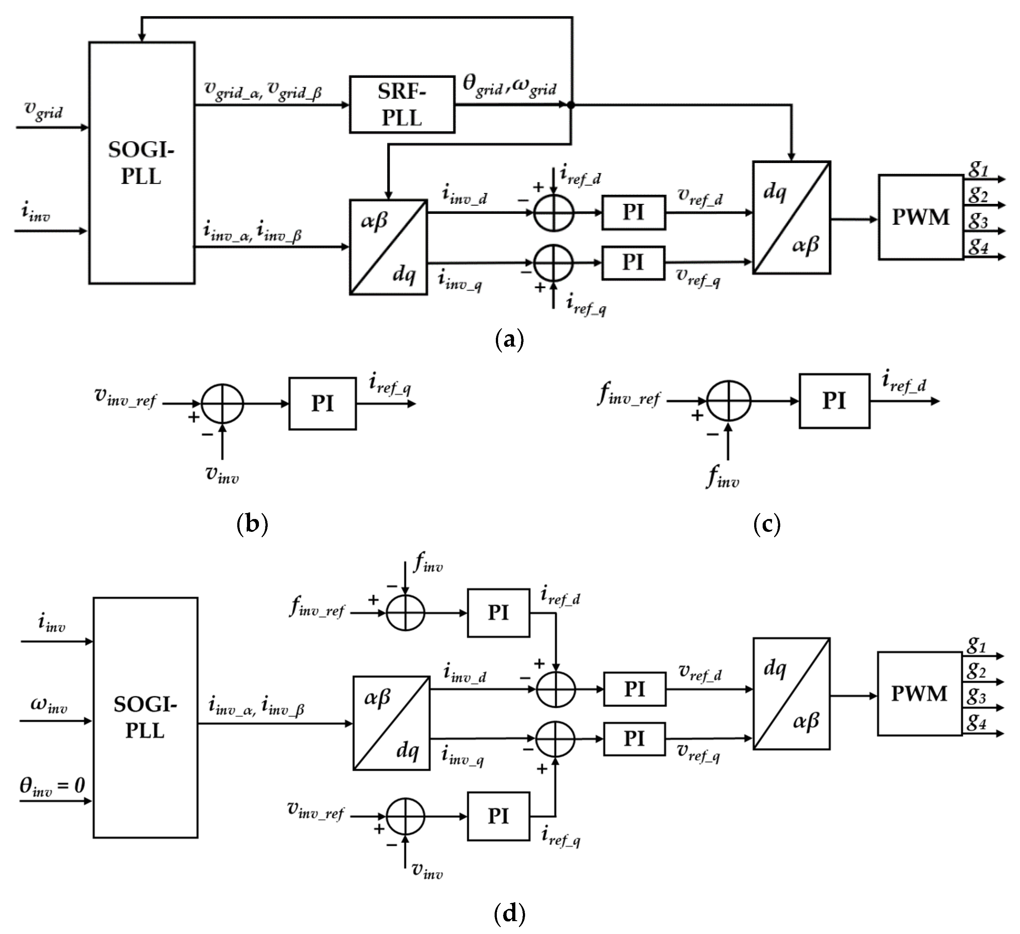
3.1.1. Main Control Scheme

Figure 5 and Figure 6a show the circuit and main control scheme of the proposed inverter. As shown in Figure 5, the proposed inverter includes four metal-oxide-semiconductor field-effect transistors (i.e., MOSFETs) with body diodes (i.e., Q1, Q2, Q3, and Q4), two inductors (i.e., L1 and L2), and a capacitor (i.e., C1) and zg (i.e., the line impedance of the grid). Q1, Q2, Q3, and Q4 are controlled by the gate control signals (i.e., g1, g2, g3, and g4). L1, L2, and C1 consist of an LCL filter for suppressing the harmonic of the proposed inverter output. The synchronous reference frame phase-locked loop (SRF-PLL) is used to synchronize the proposed inverter with the grid to achieve grid synchronization. Based on the SRF-PLL, the grid information, such as amplitude, frequency, and phase, can be determined. The closed-loop transfer function of the SRF-PLL is obtained as follows [33]:
G ( s ) = k p   ·   s + k i s 2 + k p   ·   s + k i ,
k p = 2   ·   ζ   ·   ω n ,
k p = ω n 2  
where ζ donates the damping factor, and ωn donates the natural frequency.
Then, the output of the SRF-PLL (ωgrid and θgrid) is used for the second-order generalized integrator phase-locked loop (SOGI-PLL) [34]. The SOGI-PLL is used to create two-phase orthogonal components in the α–β stationary reference frame for power calculations.
The grid voltage (vgrid), inverter output voltage (vinv), and current (iinv) are selected as the α-axis components of the fictitious two-phase system in αβ stationary reference frame as follows:
v α = v g r i d , v β = v g r i d < 90 ° i α = i g r i d , i β = i g r i d < 90 ° ,
where vα and iα are the α-axis voltage and current, respectively, and vβ and iβ are the β-axis voltage and current, respectively.
The closed-loop transfer functions (Hd(s) and Hq(s)) of the SOGI-PLL are determined as follows [35]:
H d ( s ) = k ω s s 2 + k ω s + ω 2 H q ( s ) = k ω 2 s 2 + k ω s + ω 2   ,
where k affects the bandwidth of the closed-loop system, and ω donates the grid frequency.
The inverter currents (iinv_d and iinv_q) are transformed by the Park transformation to synchronize the proposed inverter with the grid, as follows:
[ i inv _ d i inv _ q ] = [ cos θ g r i d sin θ g r i d sin θ g r i d cos θ g r i d ] [ i inv _ α i inv _ β ] ,
where θgrid is the grid phase, and iinv_d and iinv_q are compared with the inverter reference current values (iref_d and iref_q). The errors are used to calculate the reference voltage (vref_d and vref_q) by the proportional–integral (PI) controller. The duty cycle of the proposed inverter can be determined by vref_d and vref_q using the inverse Park transformation as follows:
[ v α v β ] = [ cos θ g r i d sin θ g r i d sin θ g r i d cos θ g r i d ] [ v r e f _ d v r e f _ q ] .

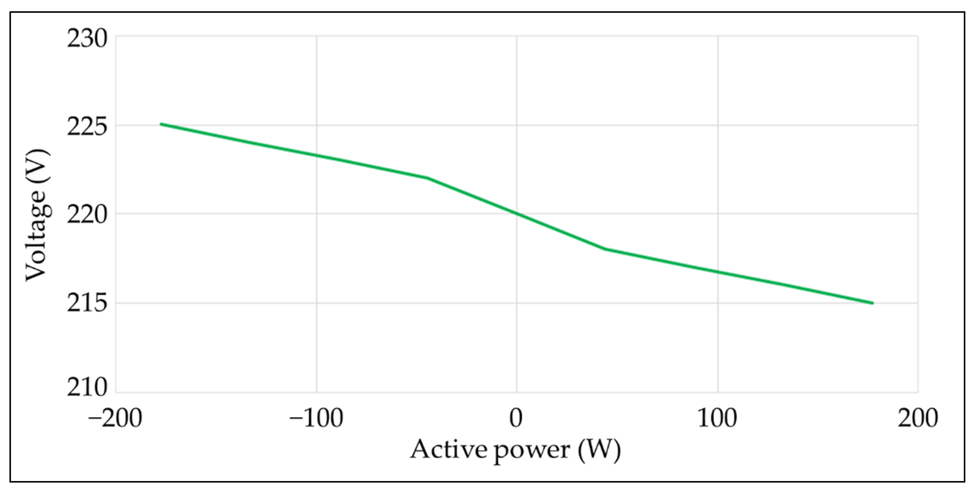
3.1.2. Voltage Compensation Control Scheme

The voltage compensation control scheme is used in the proposed inverter to reduce the voltage fluctuation, as shown in Figure 6b. The output voltage of the proposed inverter (vinv) is controlled by comparing the inverter reference voltage (vinv_ref). iref_q can be determined by a PI controller. After calculating iref_q, the voltage compensation scheme uses the same control scheme as the proposed grid-connected inverter control scheme for controlling the proposed inverter. Therefore, the inverter can reduce the fluctuation of the grid voltage.

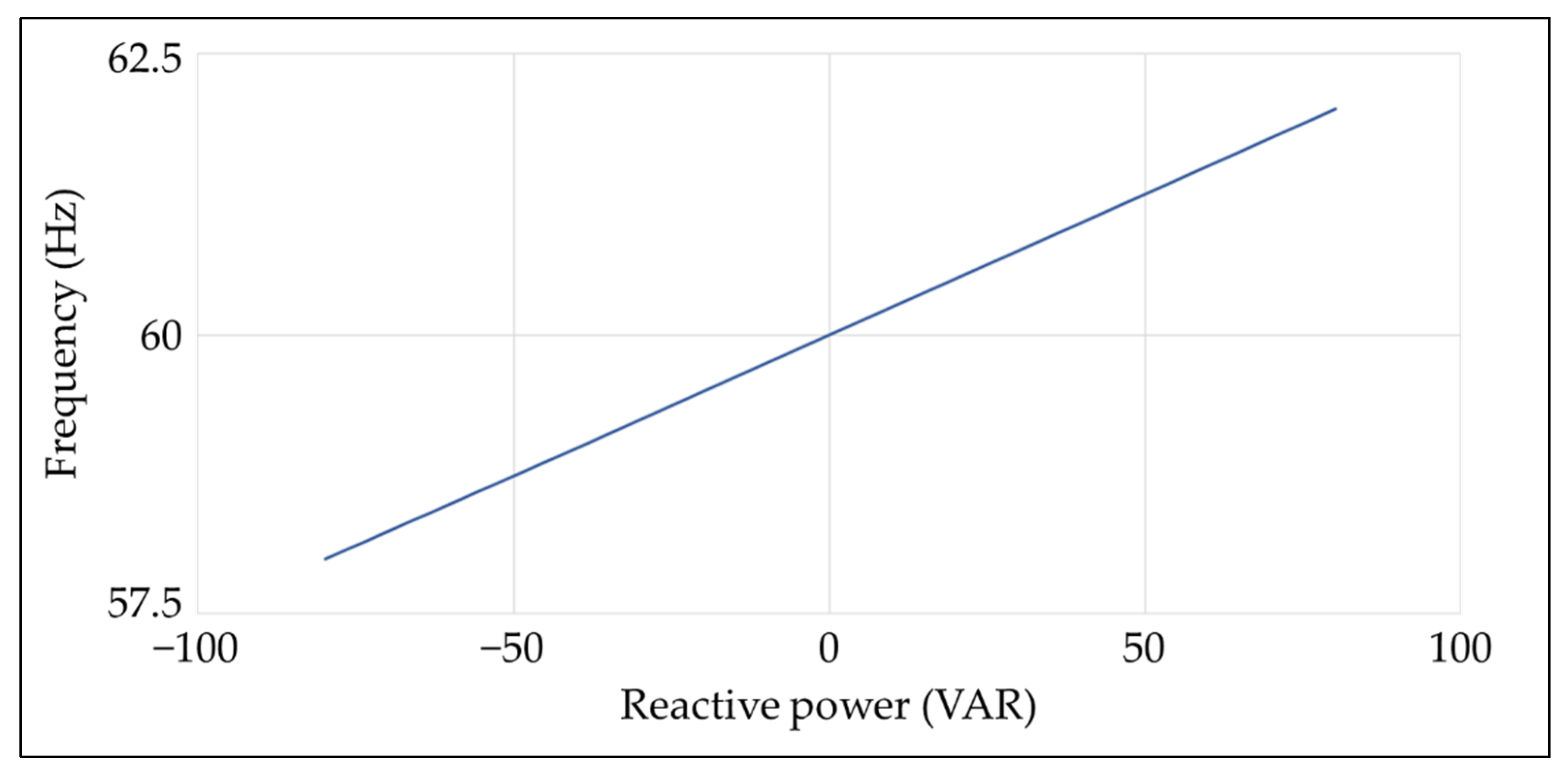
3.1.3. Frequency Compensation Control Scheme

The frequency compensation control scheme is used in the proposed inverter to reduce frequency fluctuation, as shown in Figure 6c. The output frequency of the proposed inverter (finv) is controlled by comparing the inverter reference frequency (finv_ref). iref_d can be determined by a PI controller. After calculating iref_d, the frequency compensation scheme uses the same control scheme as the proposed grid-connected inverter control scheme for controlling the proposed inverter. Therefore, the proposed inverter can reduce the fluctuation of the grid frequency.

3.2. Islanding Mode

When an islanding detection condition occurs in the microgrid, the proposed inverter can automatically detect the condition and operate in the islanding mode. The proposed inverter can provide continuous power to local loads under the same frequency and voltage level in the islanding mode. Figure 6d shows the islanding mode control scheme.
Due to islanding from the grid, the grid information, such as phase, frequency, and amplitude, cannot be detected. Thus, ωgrid and θgrid are equal to zero, which means the SRF-PLL can be removed. Otherwise, the SOGI-PLL, α–β to d–q transformation, and d–q to α–β transformation use the inverter frequency and phase (ωinv and θinv = 0). The operation of the islanding mode control scheme is the same as the grid-connected mode.

4. Experimental Setup and Results
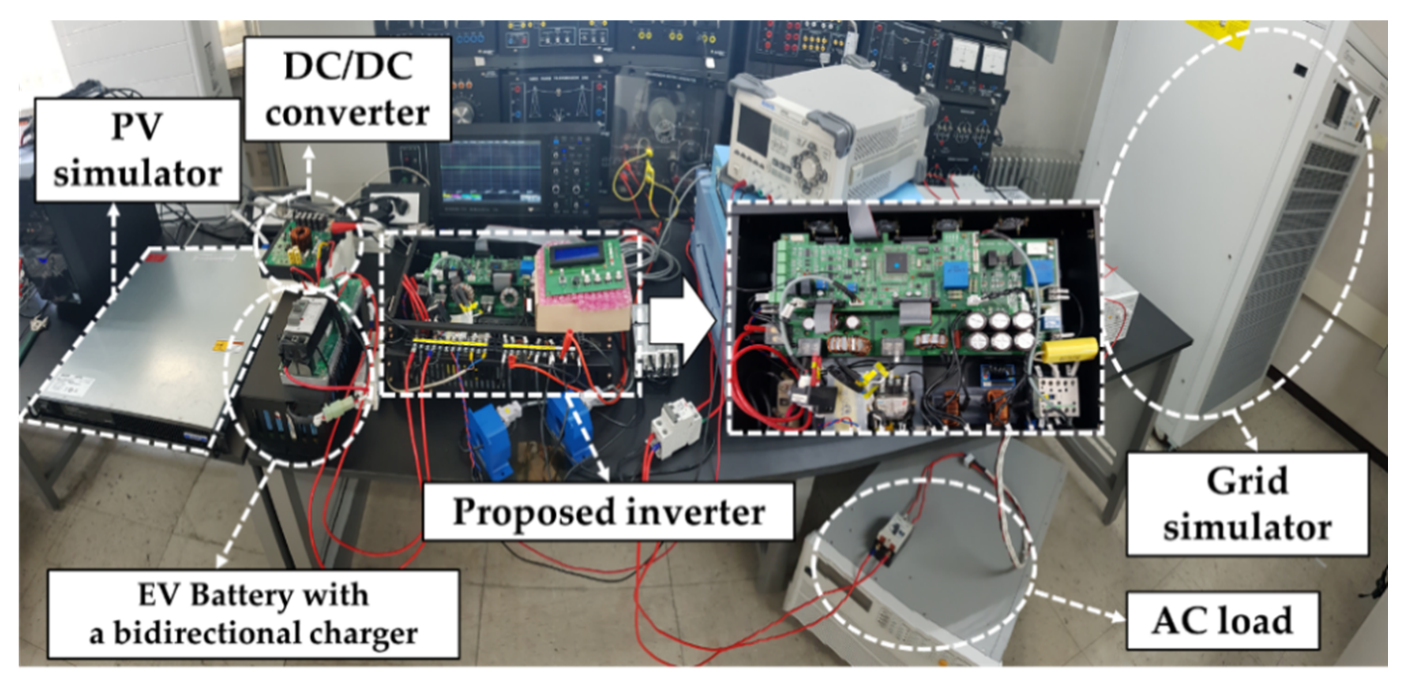
4.1. Setup

The lab-scale testbed for a PV-powered EV charging station was fabricated to verify the superiority and feasibility of the proposed inverter, as shown in Figure 7. Figure 2 shows the connection of all microgrid components. The circuit diagram of the proposed inverter circuit is depicted in Figure 5. The parameters and components of the proposed grid-connected inverter and equipment in the experiments are listed in Table 1. The proposed grid-connected inverter, which determines the appropriate operation mode based on the designed operating strategy, is located between the lab-scale testbed and the grid simulator. A PV simulator (i.e., TerraSAS ETS80) imitates the actual PV array characteristics. A PV array consists of two series-connected PV modules (i.e., NE180TU-21PS6). The output of the PV simulator is connected to a DC/DC converter, which performs MPPT using perturbation and an observation algorithm [36]. The PV simulator can supply power to a battery or the grid simulator through the DC/DC converter. The battery is used to imitate an EV battery, and the bidirectional charger is used to mimic an EV charger. The battery can be charged and discharged through the bidirectional charger. The grid simulator (i.e., CHROMA 61830) is used to imitate the grid, and the AC load (i.e., CHROMA 63803) is used to imitate a local load. The voltage and frequency of the grid simulator can be changed, and the connection can also be disconnected.

4.2. Results

The operation modes according to the operating strategy of the proposed inverter were verified based on four scenarios: grid normal conditions, grid voltage fluctuations, grid frequency fluctuations, and a blackout. Scenario 1 was used to analyze the operations mode one, mode two, mode three, and mode four under grid normal conditions. Scenarios 2 and 3 were used to analyze the voltage compensation and frequency compensation modes under grid voltage and frequency fluctuations. Scenario 4 was used to analyze the islanding mode under a blackout.

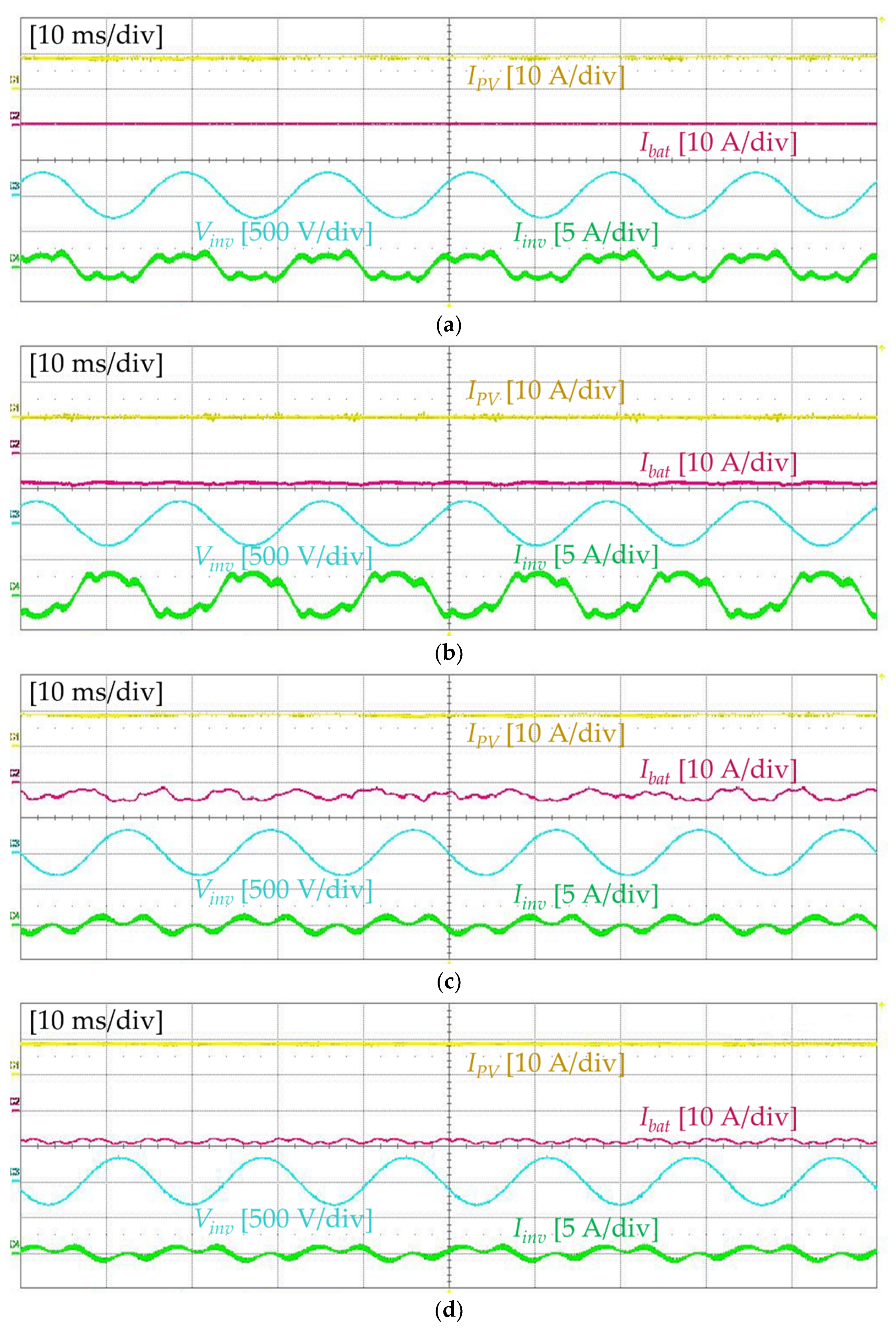
4.2.1. Scenario 1: Grid Normal Conditions

Figure 8 shows the waveforms of the PV array output current (IPV), the battery output current (Ibat), vinv, and iinv in mode one, mode two, mode three, and mode four. In mode one, the inverter supplies power generated from the PV array to the grid and the local load. As shown in Figure 8a, IPV is positive, Ibat is zero, and vinv and iinv are in phase, which means that the PV array supplies power to the grid. In mode two, EVs are charged only from the grid. As shown in Figure 8b, IPV is zero, Ibat is negative, and vinv and iinv are out of phase, which means that the grid supplies power to the EVs. In mode three, EVs are charged only from the PV array, and the inverter supplies the surplus EPV to the grid. As shown in Figure 8c, IPV is positive, Ibat is negative, and vinv and iinv are in phase, which means the PV array supplies power to the EVs and the grid. In mode four, EVs are charged from the PV array and the grid. As shown in Figure 8d, IPV is positive, Ibat is negative, and vinv and iinv are out of phase, which means that the PV array and the grid supply power to the EVs. These results prove that the proposed inverter operates in an appropriate mode according to the condition of the EVs and the PV array under grid normal conditions.

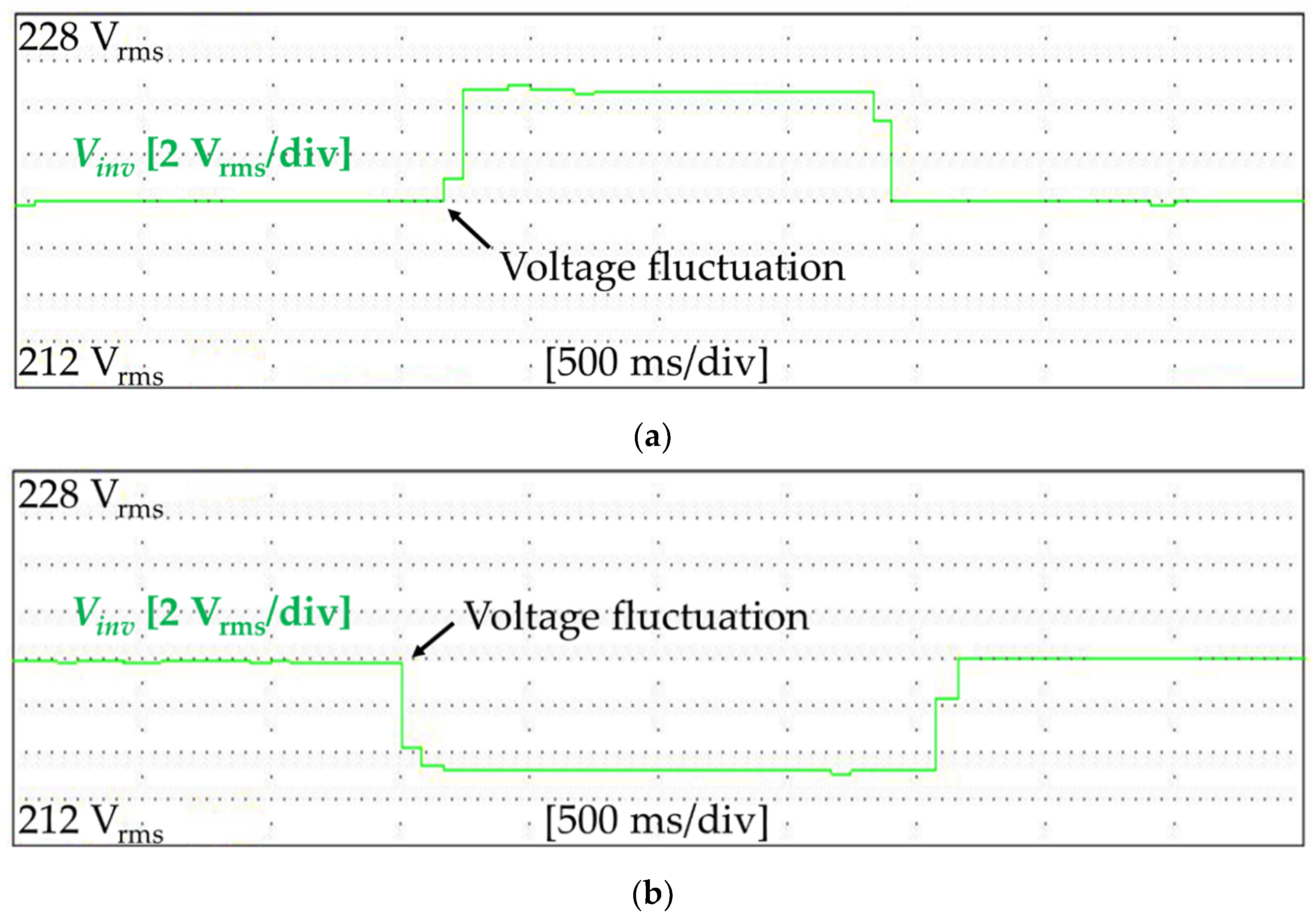
4.2.2. Scenario 2: Grid Voltage Fluctuations

Figure 9 and Figure 10 show the waveform of vinv and the relationship between the grid fluctuation voltage and the inverter output active power (Pinv) in the voltage compensation mode. The power analyzer measured all the waveforms and data (i.e., WT1806E). As shown in Figure 9a, when the grid voltage increases to 223 V, the proposed inverter operates in the voltage compensation mode and regulates the grid voltage to 220 V in 1.72 s. As shown in Figure 9b, when the grid voltage decreases to 217 V, the proposed inverter also operates in the voltage compensation mode and regulates the grid voltage to 220 V in 2.16 s. These results prove that the proposed inverter can stabilize the grid voltage by reducing the voltage fluctuation using the voltage compensation mode. In addition, Figure 10 shows that the proposed inverter regulates the grid voltage by supplying or absorbing active power to the microgrid by using V2G and PV generation in a weak grid. This means that the proposed inverter can satisfy the requirements of the grid codes, such as IEEE standard 1547–2018, for the stability of the grid.

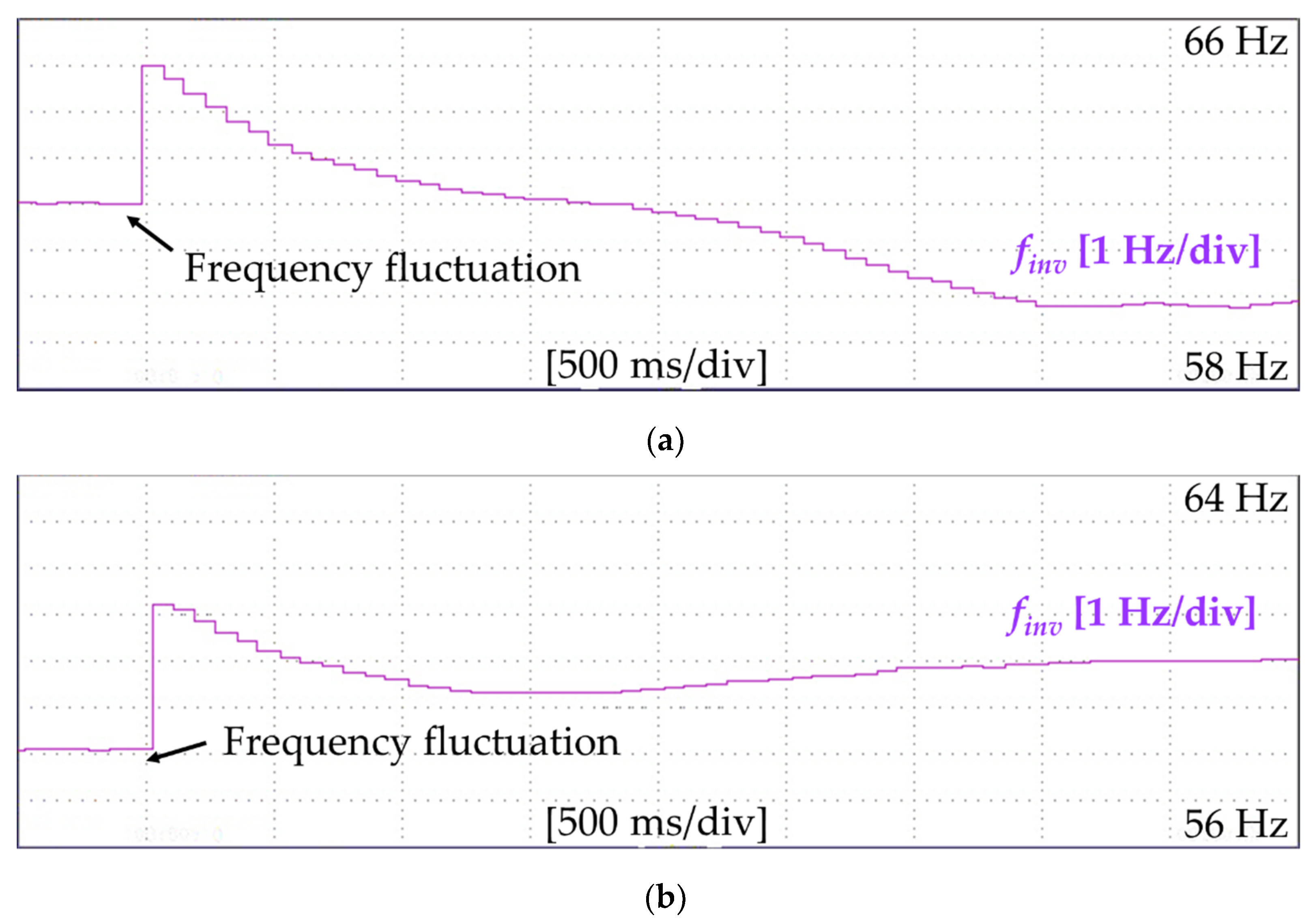
4.2.3. Scenario 3: Grid Frequency Fluctuations

Figure 11 and Figure 12 show the waveform of finv and the relationship between the grid fluctuation frequency and the inverter output reactive power in the frequency compensation mode. All the waveforms and data are measured from the power analyzer. As shown in Figure 11a, when the grid frequency increases to 62 Hz, the proposed inverter operates in the frequency compensation mode and regulates the grid frequency to 60 Hz in 3.49 s. As shown in Figure 11b, when the grid frequency decreases to 58 Hz, the proposed inverter also operates in the frequency compensation mode and regulates the grid frequency to 60 Hz in 3.69 s. These results prove that the proposed inverter stabilizes the grid frequency by reducing the frequency fluctuation using the frequency compensation mode. In addition, Figure 12 shows that the proposed inverter regulates the grid frequency by supplying or absorbing reactive power to the microgrid by using a V2G and PV generation in a weak grid. This means that the proposed inverter can satisfy the requirements of the grid codes, such as IEEE standard 1547–2018, according to the grid stability.

4.2.4. Scenario 4: Blackout

Figure 13 shows the waveforms of Vinv, Iinv, and Pinv in the islanding mode. The proposed inverter automatically detects a grid blackout event and operates in the islanding mode when a grid blackout occurs. Moreover, the inverter can provide continuous power to local loads using the PV array and the EV battery. It takes 1.86 s for the inverter to re-energize the local load after the blackout, as shown in Figure 13. This result proves that the proposed inverter can stabilize the microgrid by detecting the grid blackout event and supplying power to the local load using the islanding mode. In addition, this result means that the proposed inverter can satisfy the requirements of the grid codes, such as IEEE standard 1547–2018, about the abnormal conditions of the grid.

4.3. Comparative Study

The functions for enhancing the grid stability of the proposed inverter and a relevant study in [25] are compared in Table 2. The authors in [25] only considered the grid voltage stabilization. They did not consider the stabilization of the grid frequency, detection for the grid abnormal conditions, and operation in an islanding mode. However, the proposed inverter in this study can improve the microgrid stability of the grid voltage and frequency. Moreover, it can detect the grid abnormal conditions and operate in the islanding mode. These functions of the proposed inverter in this study comply with the grid codes, such as IEEE standard 1547–2018.

5. Conclusions

This paper proposed a grid-connected inverter for PV-powered EV charging stations to enhance microgrid stability. The proposed inverter can operate in the voltage compensation mode and the frequency compensation mode to enhance microgrid stability. If the microgrid voltage and frequency fluctuate, these operation modes can stabilize the microgrid voltage and frequency by supplying or absorbing active or reactive power to or from a microgrid using EVs and PV generation. Moreover, the proposed inverter can automatically detect the abnormal conditions of the microgrid, such as a blackout, and operate in the islanding mode. It is also possible to continuously supply power to local loads using a V2G and PV generation in the islanding mode. In addition, the proposed inverter can not only enhance the stability of the microgrid but also charge EVs in the appropriate mode according to the conditions of the EVs and PV generation.
The lab-scale testbed of the PV-powered EV charging station was built to verify the superiority and feasibility of the proposed inverter. The proposed inverter was verified in the lab-scale testbed with four scenarios, including grid normal conditions, grid voltage fluctuations, grid frequency fluctuations, and a blackout. The experiment results demonstrated that the proposed inverter satisfies the requirements of the grid codes, such as IEEE standard 1547–2018. In addition, it was proved that the proposed inverter can operate in an appropriate mode for charging EVs according to the conditions of the PV array and EVs. Therefore, by applying the proposed inverter to an EV charging station, it will be possible to charge EVs using PV generation and improve the microgrid stability.

Author Contributions

Conceptualization, Y.J., Z.S. and S.B.; methodology, Y.J., Z.S. and S.B.; software, Z.S. and C.L.; validation, Y.J., S.J. and S.C.; formal analysis, Z.S. and C.L.; investigation, Y.J. and S.J.; data curation, Y.J. and S.J.; writing—original draft preparation, Y.J., Z.S., S.J. and C.L.; writing—review and editing, D.J., S.C. and S.B.; visualization, Y.J., S.J. and D.J.; supervision, S.B.; project administration, S.B.; funding acquisition, S.B. All authors have read and agreed to the published version of the manuscript.

Funding

This work was supported by the Technology Innovation Program (20011626, Development of BMS common platforms with generality for expansion applicable xEV types by using artificial intelligent based on deep-learning) funded by the Ministry of Trade, Industry, and Energy (MOTIE, Korea).

Institutional Review Board Statement

Not applicable.

Informed Consent Statement

Not applicable.

Data Availability Statement

Not applicable.

Conflicts of Interest

The authors declare no conflict of interest.

References

  1. Cheema, K.M.; Mehmood, K. Improved virtual synchronous generator control to analyse and enhance the transient stability of microgrid. IET Renew. Power Gener. 2020, 14, 495–505. [Google Scholar] [CrossRef]
  2. Wu, G.; Sun, H.; Zhang, X.; Egea-Alvarez, A.; Zhao, B.; Xu, S.; Zhou, X. Parameter design oriented analysis of the current control stability of the weak-grid-tied VSC. IEEE Trans. Power Deliv. 2020, 36, 1458–1470. [Google Scholar] [CrossRef]
  3. Ratnam, K.S.; Palanisamy, K.; Yang, G. Future low-inertia power systems: Requirements, issues, and solutions-A review. Renew. Sustain. Energy Rev. 2020, 124, 109773. [Google Scholar] [CrossRef]
  4. Johnson, S.C.; Rhodes, J.D.; Webber, M.E. Understanding the impact of non-synchronous wind and solar generation on grid stability and identifying mitigation pathways. Appl. Energy 2020, 262, 114492. [Google Scholar] [CrossRef]
  5. Cheng, Y.; Azizipanah-Abarghooee, R.; Azizi, S.; Ding, L.; Terzija, V. Smart frequency control in low inertia energy systems based on frequency response techniques: A review. Appl. Energy 2020, 279, 115798. [Google Scholar] [CrossRef]
  6. Johnson, S.C.; Papageorgiou, D.J.; Mallapragada, D.S.; Deetjen, T.A.; Rhodes, J.D.; Webber, M.E. Evaluating rotational inertia as a component of grid reliability with high penetrations of variable renewable energy. Energy 2019, 180, 258–271. [Google Scholar] [CrossRef]
  7. Photovoltaics, D.G.; Storage, E. IEEE Standard for Interconnection and Interoperability of Distributed Energy Resources with Associated Electric Power Systems Interfaces; IEEE Std 1547-2018 (Revision of IEEE Std 1547-2003); IEEE: Piscataway, NJ, USA, 2018; pp. 1–138. [Google Scholar]
  8. Das, H.S.; Rahman, M.M.; Li, S.; Tan, C.W. Electric vehicles standards, charging infrastructure, and impact on grid integration: A technological review. Renew. Sustain. Energy Rev. 2020, 120, 109618. [Google Scholar] [CrossRef]
  9. Eldeeb, H.H.; Faddel, S.; Mohammed, O.A. Multi-objective optimization technique for the operation of grid tied PV powered EV charging station. Electric Power Syst. Res. 2018, 164, 201–211. [Google Scholar] [CrossRef]
  10. Chen, Q.; Wang, F.; Hodge, B.M.; Zhang, J.; Li, Z.; Shafie-Khah, M.; Catalão, J.P. Dynamic price vector formation model-based automatic demand response strategy for PV-assisted EV charging stations. IEEE Trans. Smart Grid 2017, 8, 2903–2915. [Google Scholar] [CrossRef]
  11. Tao, J.; Huang, D.; Li, D.; Yang, X.; Ling, C. Pricing strategy and charging management for PV-assisted electric vehicle charging station. In Proceedings of the 2018 13th IEEE Conference on Industrial Electronics and Applications (ICIEA), Wuhan, China, 31 May–2 June 2018; pp. 577–581. [Google Scholar]
  12. Saleh, B.; Yousef, A.M.; Ebeed, M.; Abo-Elyousr, F.K.; Elnozahy, A.; Mohamed, M.; Abdelwahab, S.A.M. Design of PID Controller with Grid Connected Hybrid Renewable Energy System Using Optimization Algorithms. J. Electr. Eng. Technol. 2021, 16, 3219–3233. [Google Scholar] [CrossRef]
  13. Venkatasamy, B.; Kalaivani, L. Modeling and Power Quality Analysis of Grid-Connected PV Inverter with Active and Reactive Power Injection Mode. J. Electr. Eng. Technol. 2021, 16, 1375–1387. [Google Scholar] [CrossRef]
  14. Rajamand, S. Synchronous Generator Control Concept and Modified Droop for Frequency and Voltage Stability of Microgrid Including Inverter-Based DGs. J. Electr. Eng. Technol. 2020, 15, 1035–1044. [Google Scholar] [CrossRef]
  15. Wang, D.; Locment, F.; Sechilariu, M. Modelling, Simulation, and Management Strategy of an Electric Vehicle Charging Station Based on a DC Microgrid. Appl. Sci. 2020, 10, 2053. [Google Scholar] [CrossRef] [Green Version]
  16. Yang, Y.; Jia, Q.S.; Deconinck, G.; Guan, X.; Qiu, Z.; Hu, Z. Distributed coordination of EV charging with renewable energy in a microgrid of buildings. IEEE Trans. Smart Grid 2017, 9, 6253–6264. [Google Scholar] [CrossRef] [Green Version]
  17. Clement-Nyns, K.; Haesen, E.; Driesen, J. The impact of vehicle-to-grid on the distribution grid. Electric Power Syst. Res. 2011, 81, 185–192. [Google Scholar] [CrossRef]
  18. Gong, L.; Cao, W.; Liu, K.; Zhao, J. Optimal charging strategy for electric vehicles in residential charging station under dynamic spike pricing policy. Sustain. Cities Soc. 2020, 63, 102474. [Google Scholar] [CrossRef]
  19. Wang, R.; Sun, Q.; Qin, D.; Li, Y.; Li, X.; Wang, P. Steady-state stability assessment of AC-busbar plug-in electric vehicle charging station with photovoltaic. J. Mod. Power Syst. Clean Energy 2020, 8, 884–894. [Google Scholar] [CrossRef]
  20. Singh, M.; Kumar, P.; Kar, I. Implementation of vehicle to grid infrastructure using fuzzy logic controller. IEEE Trans. Smart Grid 2012, 3, 565–577. [Google Scholar] [CrossRef]
  21. Iqbal, S.; Xin, A.; Jan, M.U.; Salman, S.; Rehman, H.U.; Shinwari, M.F.; Abdelbaky, M.A. V2G strategy for primary frequency control of an industrial microgrid considering the charging station operator. Electronics 2020, 9, 549. [Google Scholar] [CrossRef] [Green Version]
  22. Buja, G.; Bertoluzzo, M.; Fontana, C. Reactive power compensation capabilities of V2G-enabled electric vehicles. IEEE Trans. Power Electron. 2017, 32, 9447–9459. [Google Scholar] [CrossRef]
  23. Mohamed, A.A.; El-Sayed, A.; Metwally, H.; Selem, S.I. Grid integration of a PV system supporting an EV charging station using Salp Swarm Optimization. Solar Energy 2020, 205, 170–182. [Google Scholar] [CrossRef]
  24. Zhang, Y.; He, J.; Ionel, D.M. Modeling and control of a multiport converter based EV charging station with PV and battery. In Proceedings of the 2019 IEEE Transportation Electrification Conference and Expo (ITEC), Detroit, MI, USA, 19–21 June 2019; pp. 1–5. [Google Scholar]
  25. Xing, Y.Q.; Jin, J.X.; Wang, Y.L.; Du, B.X.; Wang, S.C. An electric vehicle charging system using an SMES implanted smart grid. IEEE Trans. Appl. Supercond. 2016, 26, 1–4. [Google Scholar] [CrossRef]
  26. Van Der Kam, M.; van Sark, W. Smart charging of electric vehicles with photovoltaic power and vehicle-to-grid technology in a microgrid; a case study. Appl. Energy 2015, 152, 20–30. [Google Scholar] [CrossRef] [Green Version]
  27. Hassija, V.; Chamola, V.; Garg, S.; Krishna, D.N.G.; Kaddoum, G.; Jayakody, D.N.K. A blockchain-based framework for lightweight data sharing and energy trading in V2G network. IEEE Trans. Veh. Technol. 2020, 69, 5799–5812. [Google Scholar] [CrossRef]
  28. Bansal, G.; Naren, N.; Chamola, V.; Sikdar, B.; Kumar, N.; Guizani, M. Lightweight mutual authentication protocol for V2G using physical unclonable function. IEEE Trans. Veh. Technol. 2020, 69, 7234–7246. [Google Scholar] [CrossRef]
  29. Sousa, T.; Morais, H.; Soares, J.; Vale, Z. Day-ahead resource scheduling in smart grids considering vehicle-to-grid and network constraints. Appl. Energy 2012, 96, 183–193. [Google Scholar] [CrossRef] [Green Version]
  30. Das, S.; Acharjee, P.; Bhattacharya, A. Charging Scheduling of Electric Vehicle Incorporating Grid-to-Vehicle and Vehicle-to-Grid Technology Considering in Smart Grid. IEEE Trans. Ind. Appl. 2020, 57, 1688–1702. [Google Scholar] [CrossRef]
  31. Mouli, G.C.; Bauer, P.; Zeman, M. System design for a solar powered electric vehicle charging station for workplaces. Appl. Energy 2016, 168, 434–443. [Google Scholar] [CrossRef] [Green Version]
  32. Sujitha, N.; Krithiga, S. RES based EV battery charging system: A review. Renew. Sustain. Energy Rev. 2017, 75, 978–988. [Google Scholar] [CrossRef]
  33. Golestan, S.; Guerrero, J.M. Conventional synchronous reference frame phase-locked loop is an adaptive complex filter. IEEE Trans. Ind. Electron. 2014, 62, 1679–1682. [Google Scholar] [CrossRef] [Green Version]
  34. Xiao, F.; Dong, L.; Li, L.; Liao, X. A frequency-fixed SOGI-based PLL for single-phase grid-connected converters. IEEE Trans. Power Electron. 2016, 32, 1713–1719. [Google Scholar] [CrossRef]
  35. Ciobotaru, M.; Teodorescu, R.; Blaabjerg, F. A new single-phase PLL structure based on second order generalized integrator. In Proceedings of the 2006 37th IEEE Power Electronics Specialists Conference, Jeju, Korea, 18–22 June 2006; pp. 1–6. [Google Scholar]
  36. Bhattacharyya, S.; Samanta, S.; Mishra, S. Steady Output and Fast Tracking MPPT (SOFT-MPPT) for P&O and InC Algorithms. IEEE Trans. Sustain. Energy 2020, 12, 293–302. [Google Scholar]
Figure 1. Configuration of a microgrid.
Sustainability 13 14022 g001
Figure 2. Structure of the investigated PV-powered EV charging station.
Sustainability 13 14022 g002
Figure 3. Operational strategy flowchart of the proposed inverter.
Sustainability 13 14022 g003
Figure 4. Operation modes according to the operating strategy: (a) islanding mode, (b) voltage and frequency compensation modes, (c) mode 1, (d) mode 2, (e) mode 3, and (f) mode 4.
Sustainability 13 14022 g004
Figure 5. Circuit diagram of the proposed inverter.
Sustainability 13 14022 g005
Figure 6. Control schemes of the proposed inverter: (a) main control scheme, (b) voltage compensation control scheme, (c) frequency compensation control scheme, and (d) islanding mode control scheme.
Sustainability 13 14022 g006
Figure 7. Lab-scale experimental setup.
Sustainability 13 14022 g007
Figure 8. Experimental results of scenario 1: (a) mode 1, (b) mode 2, (c) mode 3, and (d) mode 4.
Sustainability 13 14022 g008
Figure 9. Experimental results of the voltage compensation mode: (a) the grid voltage increases to 223 V; (b) the grid voltage decreases to 217 V.
Sustainability 13 14022 g009
Figure 10. Relationship between the grid fluctuation voltage and the inverter output active power in the voltage compensation mode.
Sustainability 13 14022 g010
Figure 11. Experimental results of the frequency compensation mode: (a) the grid frequency increases to 62 Hz; (b) the grid frequency decreases to 58 Hz.
Sustainability 13 14022 g011
Figure 12. Relationship between the grid fluctuation frequency and the inverter output reactive power in the frequency compensation mode.
Sustainability 13 14022 g012
Figure 13. Experimental results of scenario 4.
Sustainability 13 14022 g013
Table 1. Parameters and components of the proposed grid-connected inverter and equipment in the experiments.
Parameters, Components, and EquipmentValueUnit
Nominal input voltage Vin380V
Nominal output voltage vinv220Vrms
Nominal output frequency finv60Hz
Nominal output active power Pinv600W
Switching frequency fs20kHz
Filter inductance L1, L2625μH
Filter capacitance C110μF
MOSFET Q1, Q2, Q3, Q4IPW60R037P7
Microcontroller unitTMS320F28335
PV simulatorTerraSAS ETS80
Grid simulatorCHROMA 61830
AC loadCHROMA 63803
OscilloscopeWavesurfer 3024
Power analyzerWT1806E
Table 2. Comparative study.
FunctionProposed InverterRef. [25]
Grid voltage stabilizationYesYes
Grid frequency stabilizationYesNo
Grid abnormal conditions detection and islanding mode operationYesNo
IEEE standard 1547–2018 complianceYesNo
Publisher’s Note: MDPI stays neutral with regard to jurisdictional claims in published maps and institutional affiliations.

