Article

A Novel CNC Milling Energy Consumption Prediction Method Based on Program Parsing and Parallel Neural Network

1
Key Laboratory of Metallurgical Equipment and Control Technology, Ministry of Education, Wuhan University of Science and Technology, Wuhan 430081, China
2
Precision Manufacturing Institute, Wuhan University of Science and Technology, Wuhan 430081, China
3
Hubei Key Laboratory of Mechanical Transmission and Manufacturing Engineering, Wuhan University of Science and Technology, Wuhan 430081, China
*
Authors to whom correspondence should be addressed.
Sustainability 2021, 13(24), 13918; https://doi.org/10.3390/su132413918
Submission received: 1 December 2021 / Revised: 10 December 2021 / Accepted: 14 December 2021 / Published: 16 December 2021

Abstract

:
Accurate and rapid prediction of the energy consumption of CNC machining is an effective means to realize the lean management of CNC machine tools energy consumption as well as to achieve the sustainable development of the manufacturing industry. Aiming at the drawbacks of existing CNC milling energy consumption prediction methods in terms of efficiency and precision, a novel milling energy consumption prediction method based on program parsing and parallel neural network is proposed. Firstly, the relationship between CNC program and energy consumption of CNC machine tool is analyzed. Based on the structural characteristics of the CNC program, an automatic parsing algorithm for the CNC program is proposed. Moreover, based on the improved parallel neural network, the mapping relationship between the energy consumption parameters of each CNC instruction and the milling energy consumption is constructed. Finally, the proposed method is compared with the literature to verify the superiority of the proposed method in terms of prediction efficiency and accuracy, and the practicability of the method is verified through the case study. The proposed method lays the foundation for efficient and low-consumption process planning and energy efficiency improvement of machine tools and is conducive to the sustainable development of the environment.

1. Introduction

In 2020, China announced that it will strive to achieve carbon peak by 2030 and carbon neutrality by 2060, and for the first time to include carbon peak and carbon neutrality in the government work report [1]. The impact of the machine tool construction, regarding raw materials and energy consumption, is understood to be relatively small, as it is amortized over numerous products during the long lifetime of the machine. The full LCA revealed the significant contribution of the machine-tool structure to the global lifecycle environmental impact of the machine (about 40%), while electricity during use phase contributes about 46% to the total impact [2]. As the basic energy-consuming equipment of the manufacturing industry, CNC machine tools have the characteristics of large quantity and wide range, large total energy consumption, and low efficiency, etc., and have great energy-saving potential. Therefore, fast and accurate prediction of its machining energy consumption is an effective way to achieve optimal management of energy consumption and achieve carbon peak and carbon neutrality [3]. However, CNC machine tools are a complex multi-source energy consumption system. Different machine tool losses, machining parameters, and workpiece materials, tools, etc. have varying degrees of impact on machining energy consumption [4]. Therefore, how to accurately and efficiently predict the energy consumption of CNC machine tools has become a difficult hot spot within energy research [5]. Sihag conducted a systematic literature review on machine tool energy consumption and a six-level hierarchical model was proposed for better understanding of machining energy classification [6]. After analyzing the existing literature, the existing CNC machine tools energy consumption model research can be roughly classified into cutting force-based, electromechanical system-based, Therblig-based and data-driven-based.
The CNC machine tools energy consumption model based on cutting force is mainly based on the theoretical cutting force model proposed by MERCHANT [7,8]. These methods calculate the cutting power through the physical relationship between the cutting force and the chip speed, and calculate the energy consumption in combination with the cutting time [9,10], such as the specific energy method [11,12], the cutting force method [13], and the exponential function method [14]. This type of method only considers the cutting force parameters such as the rake angle of the tool and the amount of material removal. The theoretical calculation value and the actual machining energy consumption have a large deviation, and the application effect is not ideal [15]. In order to improve its accuracy, Zhong introduced correction coefficients in the model, combined with the cutting force and real energy consumption under different processing parameters obtained by orthogonal experiments, and corrected the coefficients through data fitting methods [16]; thereby, effectively reducing the error between the theoretical calculation value and the actual value. However, in the orthogonal experiment, only machining parameters such as spindle speed, feed rate, cutting width and depth are considered; other factors affecting machining energy consumption depend on the correction factor. At the same time, due to the relatively cumbersome calculation process, this method still has certain drawbacks in forecast accuracy and efficiency.
The CNC machine tool is a typical complex mechatronics product. Its energy consumption is essentially the process of converting the input electrical energy into kinetic energy, thermal energy and other forms of energy through various electromechanical equipment. Liu [17,18,19], Hu [20] and Shi [21] performed in-depth research on no-load energy consumption, cutting energy consumption and additional load energy consumption from the perspective of the machine tool mechanical main drive system and motor energy consumption. In view of the characteristics of multiple energy sources of CNC machine tools, Wang comprehensively modeled the entire energy flow of the machine tool from the perspective of the system, and divided the energy sources of the CNC machine tools into four categories: machining power system, machining-related auxiliary system, power-related auxiliary system and others, and established the corresponding power balance equation [22]. On this basis, Xie started from the energy consumption mechanism, and studied the predictable characteristics and prediction methods of energy consumption at various periods of the machine tool operation process [23]. Based on this energy consumption calculation method, Hu considered the influence of a part feature processing sequence on energy consumption [24]. He analyzed the relationship between CNC commands and the energy consumption of each part of the machine tool, and thus proposed a new energy consumption prediction method for CNC machine tool [25]. This kind of method analyzes and calculates the energy consumption of various subsystems in different operating stages in detail. The accuracy of energy consumption prediction has been greatly improved, but the calculation process is complicated. At the same time, it is difficult to obtain the load loss coefficient in the model, and there are very few existing methods to obtain it. Therefore, there are certain limitations in the practical applications [26].
With the deepening of research, in order to overcome the above shortcomings, Jia proposed an energy demand modeling methodology of machining processes based on Therbligs, which refer to the fundamental operations of the machine tools [27]. The machining processes are divided into a series of activities, and Therblig, as one of the basic concepts of motion study, is introduced to represent the basic energy demand unit. On this basis, Lv developed Therblig power models for calculating the energy supply of computer numerical control (CNC) machine tools using machining process parameters [28]. Then, a finite state machine (FSM)-based energy consumption modeling method of machining transient state was proposed by Jia [29] as well as the Therblig-embedded value stream mapping method for lean energy machining [30]. These methods provide more convenient new ideas for the research of machine tool energy consumption. However, because the method is based on the micro motions in the machine tool, it is still slightly complicated in the specific operation process.
With the development of machine learning and deep learning technology, the energy consumption model based on a data-driven approach has attracted the attention of scholars. Xie used a back propagation neural network (BPNN) and takes cutting speed, feed rate, and depth of cut as input parameters to construct a numerical control machine tool energy consumption prediction model, which simplifies the cumbersome calculation process of empirical formulas and achieves better prediction results [31]; Chen considered cutting speed, feed and depth of cut and other parameters, and constructed a support vector machine-based cutting energy prediction model for CNC machine tools [32]. He proposed a data-driven energy prediction approach using deep learning algorithms [33]. This method is simple and efficient, and has achieved good prediction accuracy. However, due to the few considerations of processing process parameters, it is only effective for simple processing of specific types of workpieces, and the generality and refinement of the model need to be improved. Shin proposes a predictive modeling approach based on historical data collected from machine tool operations [34].
In summary, the current energy consumption prediction of CNC machine tools has mainly the following problems. First, the calculation process of energy consumption based on cutting force or electromechanical system is complicated, and the cutting force and correlation coefficient are difficult to accurately obtain. Second, the load loss of different machine tools is different, it is difficult to obtain the load loss coefficient, and it is difficult to establish a general energy consumption calculation model. Third, the data-driven energy consumption prediction method could solve the above two problems well, but the current research is insufficient and it is difficult to adapt to the wide range of production needs. In response to the above problems, a novel CNC milling energy consumption prediction method based on program parsing and parallel neural network is proposed. First of all, the tool path, processing parameters and other machine energy consumption parameters are automatically extracted from the processing program through the constructed CNC program parser. Then the parameters are classified based on energy consumption characteristics of CNC machine tools. For each type of parameter, the corresponding neural network is used to predict its machining energy consumption. The sum of the parallel operation results of multiple neural networks is the total machining energy consumption. This method directly establishes the mapping relationship between the CNC program and the energy consumption of the CNC machine tool, and comprehensively considers the factors affecting the energy consumption of the CNC machine tool. Moreover, the prediction accuracy and efficiency can be effectively improved by parallel neural networks. Based on the proposed method, the energy consumption prediction of CNC machine tools can be realized more efficiently and accurately, which lays the foundation for efficient and low-consumption process planning and energy efficiency improvement of machine tools.
The remainder of this paper is organized as follows. The energy consumption characteristics of CNC machine tools are analyzed in Section 2. Section 3 presents the general framework of the proposed model, and provides an introduction to the CNC program parser and parallel neural network used for the energy prediction model. Case verification and comparative analysis of results are given in Section 4. Finally, conclusions are drawn in Section 5.

2. Analysis of Energy Consumption Characteristics of CNC Machine Tool Machining

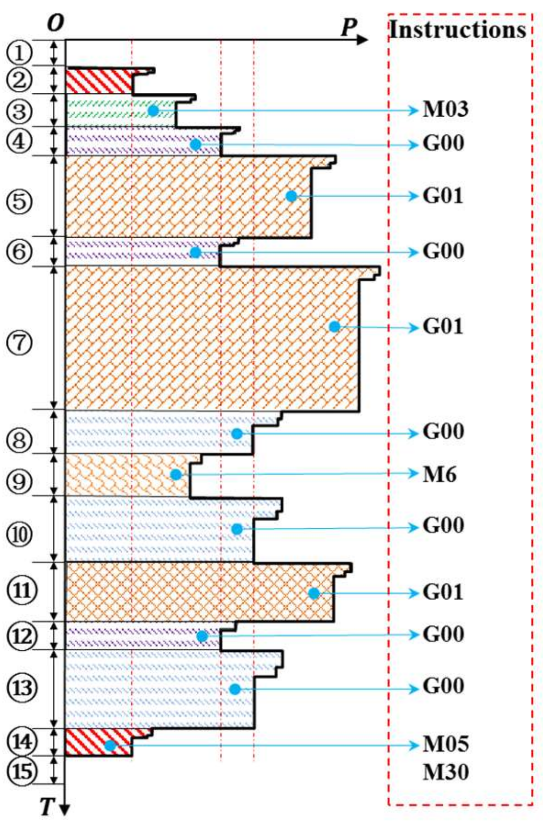
CNC machine tools processing common features such as planes, grooves, and holes, etc., mainly include states such as start-up, standby, spindle start and stop, rapid feed, linear interpolation, tool change, and drilling. As shown in Figure 1, the left side is a simplified diagram of the power change curve under different processing conditions. The horizontal axis is power (P), the vertical axis is time (T), and on the right is the CNC programs corresponding to each machining stage.
It can be seen from Figure 1 that the power of the machine tool is different under different CNC instructions. When the instruction changes, its power will suddenly change in a short time and quickly stabilize until the command is executed. In stages ① and ⑮, the machine tool is in a stopped state, and the power at this stage is 0. During phase ② and ⑭, the machine tool starts to enter the standby state; at this time, only the control system, display system and other machine tool auxiliary systems are running. After executing the instruction M03, the spindle rotates forward and enters phase ③; phases ④, ⑥, ⑫, ⑧, ⑩, and ⑬ are all rapid traverse movements of the tool after G00 instruction is executed, and their movement speeds are set by the machine tool by default. However, due to the different starting and ending points, the number of servo motors involved in the work in the X, Y, and Z directions of the machine tool is different, which ultimately leads to different powers at each stage. During ④, ⑥, and ⑫ stages only the Z coordinate changes, and the X and Y coordinates remain unchanged. Therefore, only the Z-axis servo motor participates in the work, and the X and Y-axis servo motors do not participate in the work. However, in the stages ⑧, ⑩, and ⑬, the coordinates in the three directions of X, Y, and Z have changed. The servo motors in the three directions of the process participate in the work, so the power is higher. Stages ⑤, ⑦, and ⑪ are all linear interpolation movements of the tool after executing the G01 command. At this stage, the tool contacts the workpiece and starts cutting. Due to the cutting depth of stage ⑦ being deeper than the cutting depth of stage ⑤, stage ⑦ is more powerful than stage ⑤. Stage ⑪ is milling only in Z direction, and the feed rate is reduced, so the power of stage ⑪ is different from stages ⑤ and ⑦. In stage ⑨, the tool is changed after executing the tool change command.
Through the above analysis and literature [35,36] research, it can be seen that CNC instructions determine the motion mode of CNC machine tools. CNC machine tools have different energy consumption characteristics under different CNC instructions (such as G00 and G01, etc.). The energy consumption of CNC machine tools under the same CNC instruction and different processing parameters is also different, but they have similar energy consumption characteristics. Therefore, the mapping relationship between the machining process parameters and the energy consumption of the CNC machine tool under each CNC command can be established, so as to predict the energy consumption of the workpiece machining. The corresponding relationship between commonly used CNC instructions and energy consumption parameters is shown in Table 1. The row is all the energy consumption parameters, and the column is the commonly used CNC instructions. “●” indicates that the row of commands is related to the energy consumption parameters in corresponding column.
In the process of general parts processing, the machine tool is in one of four states: standby, tool change (T), rapid positioning (G00), and linear interpolation (G01). Among them, the power of the machine in the standby state is a constant value, and its energy consumption is only related to the standby time. The tool change process is divided into two steps: rapid positioning to the tool change point (G00) and tool change. Therefore, the energy consumption of this process is mainly related to the current tool number and the end tool number. The energy consumption of linear interpolation is the most complicated in the whole machining process. It mainly includes cutting energy consumption and auxiliary energy consumption. Cutting energy consumption mainly includes spindle speed, tool material, tool diameter, number of cutting edges, back-cutting amount, side-cutting amount, feed speed, workpiece material and other process parameters. Therefore, the energy consumption E t o t a l in the entire part processing process can be expressed as:
E t o t a l = i = 1 N E i
E i = k = 1 K i f i ( a i 1 k , a i 2 k , , a i j k , a i J i K i )
where E i is the energy consumption under the i -th type of CNC instruction, N is the type of CNC instruction in the machining program,   a i j k is the i -th processing parameter when the j -th type of instruction appears for the k -th time, j = 1 , 2 , , J i , k = 1 , 2 , , K i , J i are the processing parameters of the i -th instruction, K i   is the number of occurrences of the i -th instruction, f i is the difference between the energy consumption of the CNC machine tool and the processing technological parameters under the i -th instruction mapping relations.

3. Energy Consumption Prediction Model of CNC Machine Tool

3.1. Process of Energy Consumption Prediction

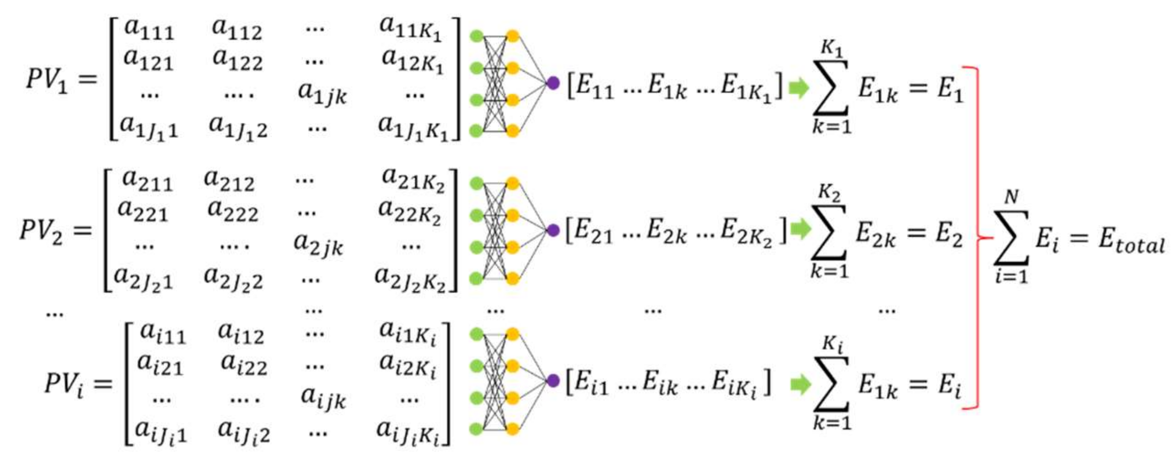
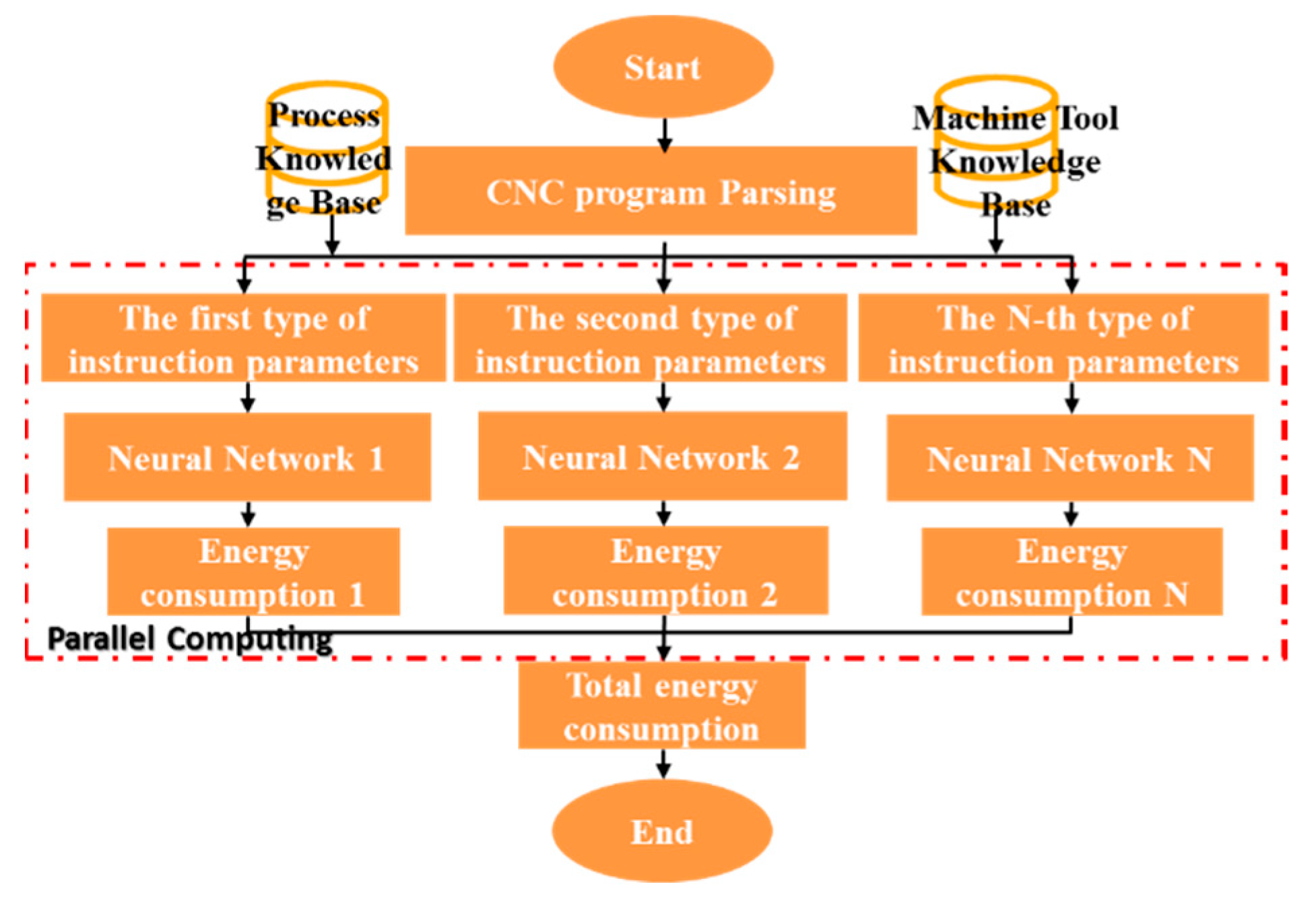
The energy consumption prediction process of CNC machine tools based on program decomposition and multiple neural networks is shown in Figure 2, which mainly includes the following three steps. First, combining the numerical control processing knowledge base and the machine tool knowledge base to analyze the numerical control program, obtain the kth group of processing technology parameter set corresponding to the i -th type numerical control instruction [ a i 1 k , a i 2 k , , a i j k , a i J i k ] . Second, for each group of processing process parameters, the energy consumption E i k is predicted through the corresponding neural network, and sum the energy consumption values of group K i in the i -th type of CNC instructions to obtain the energy consumption E i corresponding to each type of numerical control instruction. In order to improve the efficiency of prediction, the process uses multiple neural networks to calculate in parallel. Finally, sum the energy consumption of N types of CNC instructions [ E 1 , E 2 , E i , , E N ] , which is the predicted value of total energy consumption   E t o t a l for CNC machine tool processing. Among them, CNC program analysis and multi-neural network parallel calculation are the key to the energy consumption prediction method of numerical control machine tools.

3.2. Parsing Method of CNC Program

The CNC program is a structured text document, which mainly includes three parts: the program number, the program content and the end of the program. The program content is the core of the entire CNC program, and it is also the content that this article needs to analyze. Each line of the program content is a block, and each block is composed of one or more instruction words. The general format is “block number CNC instruction coordinates other parameters”. Each instruction word is separated by a space, which is easy to parse. The pseudo code of the CNC parsing program is shown in Algorithm 1.
Algorithm 1. CNC program parsing pseudo code.
Input: CNC programProcess knowledge set P K , Machine tool knowledge set M K
Output: parameter value matrix of classified CNC instruction P V i J i K i
1. Initialize the CNC instruction set   C N C 1 × N , CNC instruction parameter set   P N × J m a x , machine tool status parameter set S T 1 × M , flag set K 1 × N = o n e s   1 , N
2. R o w = read first line
3. while (‘M30’ not in Row)
4.    cnc = obtain the instruction in Row
5.    n = find(CNC==cnc)
6.    params = P(n)
7.    for a = 1:size(params)
8.        pv = calculate the value of params(a) according S T , P K   and   M K
9.        PV(n,a,K(n)) = pv
10.    end for
11.    update S T
12.    K(n) = K(n) + 1
13.    Row = read next line
14. end while
The input of Algorithm 1 is the numerical control program, the machining process knowledge collection P K and the numerical control machine tool knowledge collection M K , among which the numerical control program is the algorithm analysis object. P K includes machining process knowledge such as machine preparation time, workpiece material and size, CNC machining workpiece coordinate system, etc. This knowledge can be obtained directly from the part processing process card and stored in the form of key-value pairs, which is convenient for program reading; M K also stores basic information such as the rated power of the machine tool and the torque, power, and speed of the servo motor in the form of key-value pairs. The algorithm output is the parameter matrix P V i J i K i corresponding to various CNC commands.

3.3. Improved BPNN

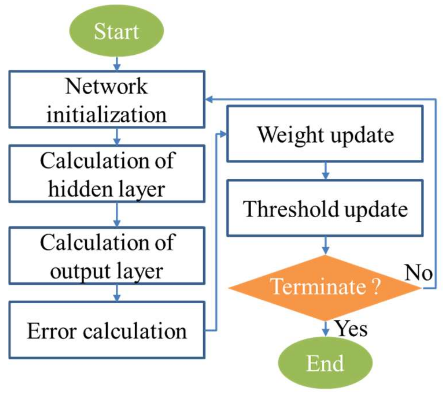
BPNN is a parallel information processing method that can calculate complex nonlinear relationships by learning models and using experimental data. It has been widely used in prediction, data classification, feature recognition and nonlinear function approximation [37]. The training process of BPNN is shown in Figure 3.
Step1: Network initialization. According to the system input   X = ( x 1 , x 2 , , x n ) and output   Y = ( y 1 , y 2 , , y m ) , determine the number n   of input layer nodes, the number   l of hidden layer nodes, and the number m   of output layer nodes, and initialize the connection weights ω i j ,   ω j k between the input layer, hidden layer and output layer neurons, initialize hidden layer threshold   a , output layer threshold b , given learning rate and neuron activation function.
Step2: Hidden layer output calculation. The hidden layer output H is calculated according to the input vector X , the connection weight ω i j between the input layer and the hidden layer, and the hidden layer threshold a .
H j = f ( i = 1 n ω i j x i a j )             i = 1 , 2 , , n ;   j = 1 , 2 , , l
In the formula, l is the number of hidden layer nodes; f is the hidden layer activation function, which has many expressions. The selected function as follows:
f ( x ) = 1 1 + e x
Step3: Calculation of the output layer. According to the hidden layer output H , the weight ω j k and the threshold b , the BPNN predictive output O is calculated as follows.
O k = j = 1 l H j ω j k b k               k = 1 , 2 , , m
Step4: Error calculation. According to the predicted output of the network O and the expected output Y , the network predicted error e is calculated.
Step5: Weight update. The network connection weights ω i j , ω j k are updated according to the network prediction error e .
ω i j = ω i j + η H j ( 1 H j ) x ( i ) k = 1 m ω j k e k   i = 1 , 2 , , n ; j = 1 , 2 , , l ; k = 1 , 2 , , m
ω j k = ω j k + η H j e k           j = 1 , 2 , , l ; k = 1 , 2 , , m
In the formula, η is the learning rate.
Step6: Update the threshold. Update the network node thresholds   a , b according to the network prediction error e .
a j = a j + η H j ( 1 H j ) k = 1 m ω j k e k         j = 1 , 2 , , l
b k = b k + e k
Step7: Judge whether the algorithm iteration is over, if it is not over, go back to step 2.
In order to improve the training efficiency and prediction accuracy of neural network, it is optimized through additional momentum method and adaptive learning rate.
(1)
Additional momentum method
BPNN uses a gradient correction method as the update strategy of weights and thresholds. The weights and thresholds are corrected from the negative gradient direction of the network prediction error. The accumulation of previous experience is not considered, and the learning process converges slowly. In response to this problem, the additional momentum method is used to optimize it, and the weight learning formula with additional momentum is as follows.
ω   ( k ) = ω   ( k 1 ) + Δ ω   ( k ) + a [ ω   ( k 1 ) ω ( k 2 ) ]
In the formula, ω   ( k ) , ω   ( k 1 )   and   ω   ( k 2 ) are the weights at k , k 1   and   k 2 , respectively; a   is the momentum learning rate.
(2)
Adaptive learning rate
The value of BPNN learning rate η is between [ 0 ,   1 ] , the larger the learning rate η , the greater the modification of the weights, and the faster the network learning speed. However, a too large learning rate η will cause oscillations in the weight learning process, and a too small learning rate will cause the network to converge too slowly, and the weights will be difficult to stabilize. The adaptive learning rate method means that the learning probability η is relatively large in the early stage of BPNN evolution, and the network converges quickly. As the learning process progresses, the learning rate continues to decrease, and the network tends to stabilize. The formula for calculating the adaptive learning rate is as follows.
η ( t ) = η m a x t ( η m a x η m i n ) / t m a x
In the formula, η m a x is the maximum learning rate; η m i n is the minimum learning rate; t m a x is the maximum number of iterations;   t is the current number of iterations.

3.4. Energy Consumption Prediction Model of CNC Machine Tools Based on IPBPNN

It can be seen from Table 1 that the process parameters corresponding to different numerical control instructions are quite different. If energy consumption is predicted for all numerical control instructions through a large neural network, the neural network input layer is all the process parameters in Table 1, and the input matrix is a relatively large one. A large sparse matrix is not conducive to network training and prediction accuracy. Therefore, a small neural network is constructed for each type of CNC instruction. The input layer of each neural network is the process parameter corresponding to the type of CNC instruction. The containing layer is determined by empirical formula (12) [38].
l < m + n + a
In the formula, n is the number of input layer nodes, l is the number of hidden layer nodes, m is the number of output layer nodes, and a is constant between 0 and 10. In this article, the selection of the number of hidden layer nodes first refers to the formula to determine the approximate range of the number of nodes, and then cross-validation is used to determine the optimal number of nodes in the hidden layer. The energy consumption prediction model of CNC machine tools based on improved parallel BPNN (IPBPNN) is shown in Figure 4, where the input matrix P V   is the output of Algorithm 1.

4. Results

In order to verify the energy consumption prediction model of CNC machine tools based on IPBPNN proposed in this paper, the basic data of machining energy consumption of CNC machine tools under different instructions and different process parameters are obtained through design experiments. The parallel neural network model proposed in Section 3.4 is designed and trained for different instructions. It is used to predict the energy consumption of the work piece and the results are analyzed.

4.1. Experimental Design and Data Acquisition

This article takes the XH714D CNC machining center produced by Hanchuan Machine Tool Plant as the experimental object, and its parameters are shown in Table 2.
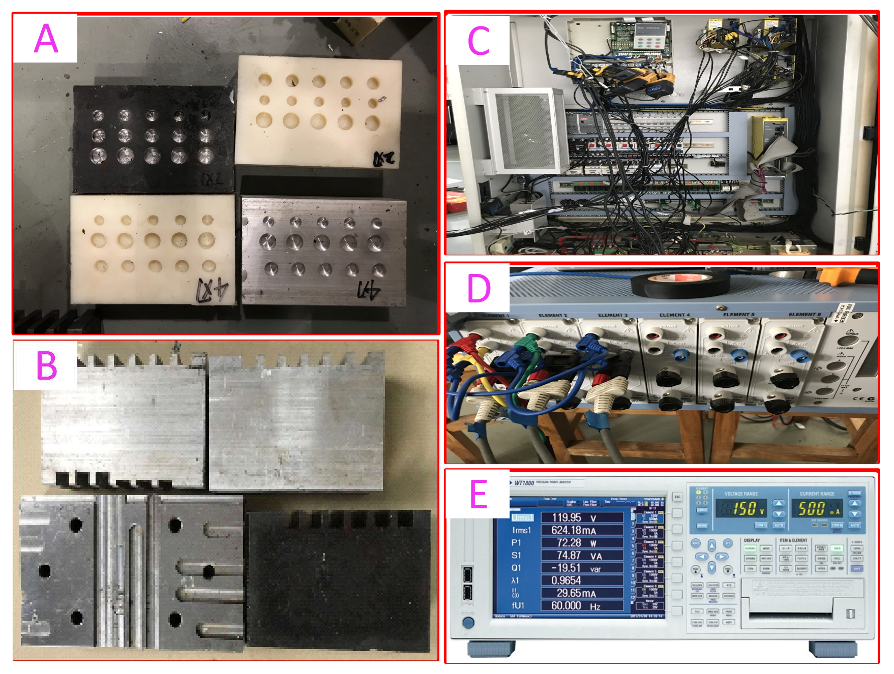
The experimental device is shown in Figure 5, where A and B are cutting samples of different materials (PA6 nylon, aluminum alloy, 45# steel, etc.), C is the wiring diagram of the energy consumption measurement of the machining center, and D is the wiring of the WT1800 high-precision power analyzer. In the figure, E is the operation interface of the power analyzer.
Because common features such as planes, grooves, and holes can be processed by G00, G01, M, and T commands, this article mainly verifies the standby energy consumption and the machining energy consumption of T, G00, and G01 commands. The curve of standby energy consumption and tool change energy consumption is shown in Figure 6.
Figure 6a shows the maximum, average, and minimum energy consumption of the machine tool for different durations, which are recorded once every 30 s after the machine is running smoothly in standby and repeated ten times under the same conditions. It can be seen from the figure that the standby energy consumption of the machine tool is linearly related to the standby time. The CNC machining center comes with a disc tool magazine, which can accommodate 12 tools. After executing the T command, the milling tool on the spindle is first placed back to the current empty position of the tool magazine, and then the tool magazine rotates one tool position at a time until the designated tool is rotated to the tool change position, and finally the tool is clamped to the spindle to complete tool change. During the experiment, the energy consumption of changing from any tool to the other 11 tools in the standby state was measured multiple times, and grouped according to the number of tool offenses. The maximum, average, and minimum energy consumption of each group are shown in Figure 6b. It can be seen from Figure 6b that the tool change energy consumption curve is symmetrically distributed with the number of offside six as the center. As the number of offside of tool change increases, the energy consumption of tool change continues to increase. It reaches the maximum when the number of offside is six, and then decreases sequentially, and the energy consumption E and the number of offside n satisfy the following relationship.
E n = E 12 n             n = 1 , 2 , , 11
When changing tools, the tool magazine rotates clockwise or counterclockwise, and always moves the designated tool to the tool change position with the minimum number of rotations, thereby reducing machine tool energy consumption and tool change time.
The energy consumption of CNC machine tools is affected by many factors in Table 3 and Table 4 when executing commands such as G00 and G01. In order to improve the efficiency of the experiment and the accuracy of the experimental results, the orthogonal experiment method is used to obtain the energy consumption characteristic data [39]. The orthogonal experiment factors and levels of the energy consumption characteristics of G00 and G01 commands are shown in Table 3 and Table 4, respectively. Therefore, the mixed horizontal orthogonal experiment schemes are L 49 ( 7 × 5 3 ) and L 64 ( 7 × 3 × 4 × 5 6 ) . The experimental material is aluminum alloy.

4.2. IPBPNN Training and Testing

According to the calculation of empirical formula (12), the number of hidden layer neurons of the neural network corresponding to the G00 instruction is [3,13], and G01 is [4,14]. Randomly take 80% of each data set (39 G00 data, 51 G01 data) to determine the optimal neural network structure through cross-validation. The neural network structure parameters of different CNC commands are shown in Table 5. Due to the large range of output energy consumption values, the mean relative error (MRE) is used to measure the prediction accuracy:
M R E = 1 N i = 1 N | y i y i | y i
where   y i   is the predicted value of the i -th sample, y i is the true value of the i -th sample, and the cross-validation error is shown in Figure 7.
It can be seen from Figure 7 that the optimal structure of G00 neural network is 4 × 3 × 1, and the optimal structure of G01 neural network is 9 × 10 × 10 × 1. On this basis, the network parameters with the lowest relative error are selected as the optimal neural network parameters, and the remaining 20% (10 G00 data, 13 G01 data) data are used to test each neural network.
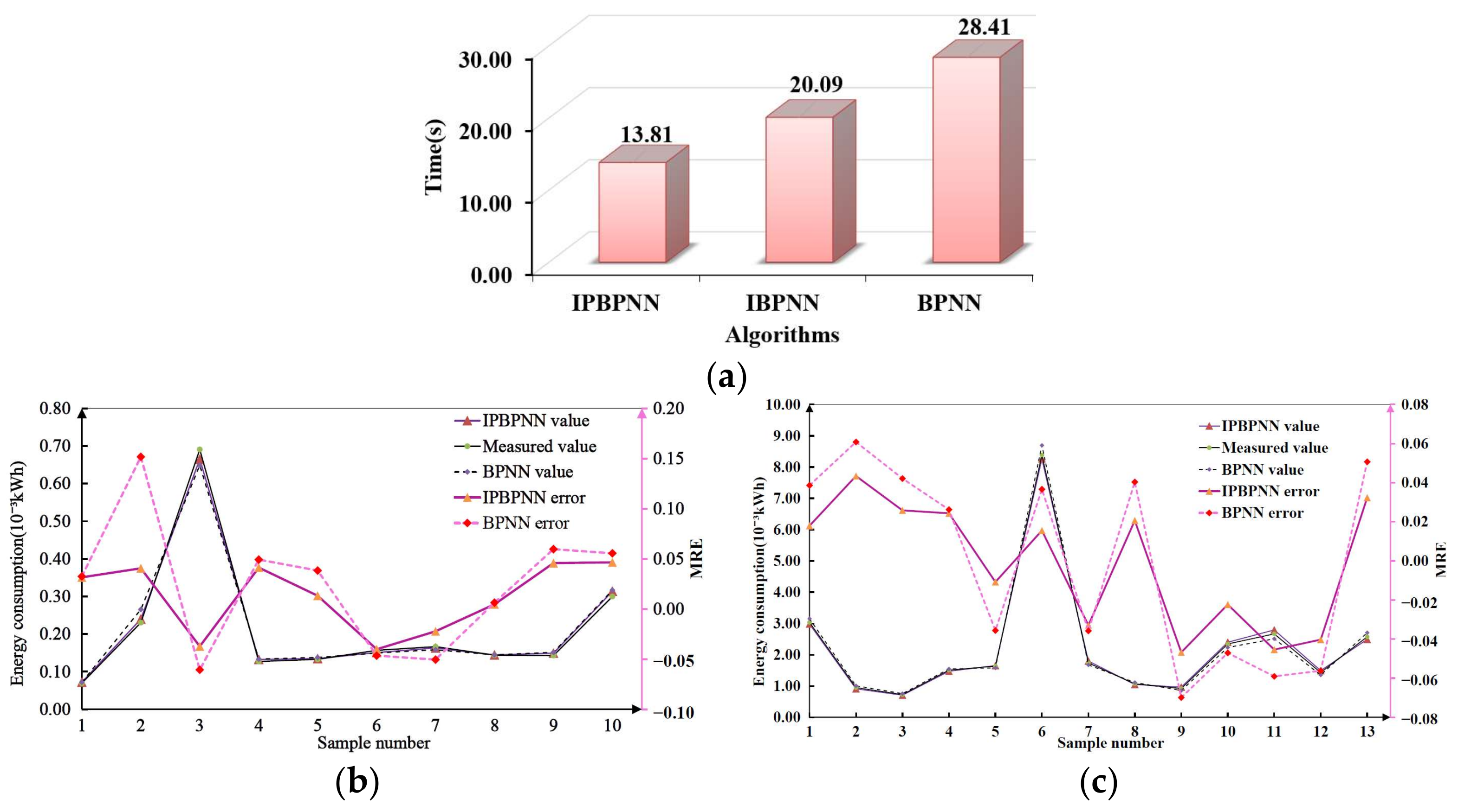
To verify the advantage of the proposed algorithm, the BPNN based numerical control milling energy consumption prediction method proposed by Xie [31] was used for comparison. Because Xie did not predict the energy consumption of G00, and only considered the three factors of cutting speed, feed rate and cutting depth when predicting the energy consumption of G01, in order to ensure the comparability of the method, this article only uses Xie’s BPNN method, and input parameters are consistent with IPBPNN. The comparative result is shown in Figure 8.
Figure 8a is the comparison of the training time of different algorithms for G00 and G01 instructions. The time corresponding to IPBPNN is the parallel training time of G00 and G01, and the time corresponding to IBPNN and BPNN is the total time of G00 and G01 serial training. The training termination conditions all have an error of 10 6 . It can be seen from the figure that the BPNN improved by the additional momentum method and the adaptive learning rate has a 29.28% improvement in training time compared to the BPNN. At the same time, after G01 and G00 are trained in parallel, IPBPNN has a 31.27% reduction in training time compared to IBPNN, and compared with Xie’s BPNN algorithm the training time has been reduced by nearly half. It can be proved that the IPBPNN proposed in this article has higher training efficiency.
It can be seen from Figure 8b,c that the energy consumption predicted by IPBPNN has an error of less than 5% compared with the measured value, and the maximum error of BPNN’s prediction results reached 6.99%, but it was still smaller than Xie’s 8% error. On the one hand, the prediction model of this article considers more energy consumption factors, such as the back engagement, the working engagement and the number of blades, etc., on the other hand, the IPBPNN algorithm proposed in this article has higher accuracy.

4.3. Prediction and Analysis of Sample Energy Consumption

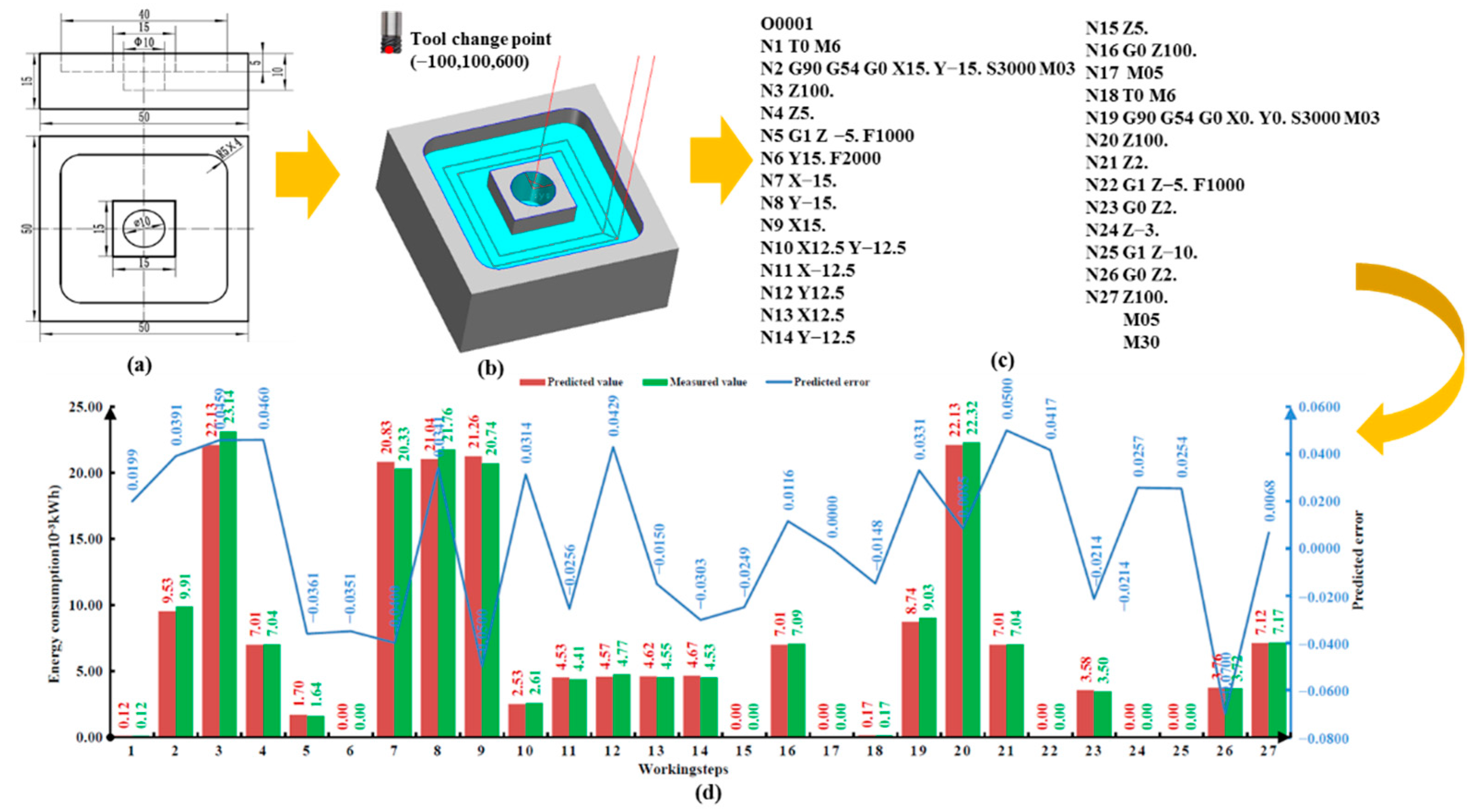
In order to further verify the versatility of the method, the energy consumption of parts processing as shown in Figure 9a was predicted and compared with the actual measured value. This part contains common processing features such as blind holes and grooves. G01 plane processing is used for grooves, and G01 drilling is used for blind holes. The specific processing tool path is shown in Figure 9b. The origin of the workpiece coordinate system is the center point of the upper surface of the workpiece, and the coordinate of the tool change point is (−100, 100, 600). On this basis, the CNC milling program generated by the CAXA manufacturing engineer software is shown in Figure 9c, where the machining process with the program segment numbers N1-N27 is included in the energy consumption. Because the execution process of M05 and M30 is extremely short, its energy consumption is negligible. After analyzing the program through Algorithm 1, the tool change, G00 and G01 parameter matrices P T , P G 00 , P G 01   can be obtained, respectively.
P T = [ 2 1 1 8 ]
P G 00 = [ 3000 3000 3000 3000 0 3000 3000 3000 1500 1500 1500 115 0 0 0 112.5 100 0 0 0 0 0 115 0 0 0 112.5 100 0 0 0 0 0 0 500 95 95 500 0 500 95 3 8 98 ]
P G 01 = [ 3000 3000 3000 3000 3000 3000 3000 3000 3000 3000 3000 1500 1500 1500 4 4 4 4 4 4 4 4 4 4 4 2 2 2 2.5 0 10 10 10 10 2.5 2.5 2.5 2.5 0 0 0 0 5 10 5 5 5 5 5 5 5 5 0 10 0 10 1000 1000 1000 1000 1000 1000 1000 1000 1000 1000 1000 200 200 200 50 50 50 50 50 50 50 50 50 50 50 25 25 25 0 0 30 0 30 2.5 25 0 25 0 0 0 0 0 0 30 0 30 0 2.5 0 25 0 25 0 0 0 0 10 0 0 0 0 0 0 0 0 0 5 7 5 7 ]
Through P T and the linear relationship in Figure 6, the energy consumption of each tool change process and standby can be obtained. Input P G 00 and P G 01 into the neural network trained in 3.2, and the energy consumption of each processing step can be calculated as shown in Figure 9d. The red bar graph represents the predicted energy consumption value, the green bar graph represents the actual energy consumption value measured in the experiment, and the blue curve represents the predicted error. The total machining energy consumption is predicted to be 185.60 × 10 3 k W h , and the total machining energy consumption is 184.08 × 10 3 k W h measured by the experiment, and the total energy consumption prediction error is 0.82%. It can be seen that this method has high prediction accuracy and stability in the prediction of energy consumption in the process step and the prediction of total energy consumption.
During the industrial application, after the CNC program of the components are designed, the machining energy consumption can be predicted through the proposed method. Moreover, the numerical control processing parameters can be optimized by the energy consumption of each line of the program, and even the structural design of the parts can be optimized, so that the machining energy consumption is the lowest and the highest efficiency, so as to achieve low energy consumption, high efficiency and sustainable production.

5. Conclusions

In this paper, a novel CNC milling energy consumption prediction method based on program decomposition and IPBPNN is presented. The effectiveness and superiority of this method have been verified by experiments. First of all, the extraction and classification of the instructions and parameters of the CNC program are effectively completed through the proposed automatic parsing algorithm. Then, based on the parallel neural network, the mapping relationship between the CNC command parameters and energy consumption was established, and the hyperparameters and parameters of each neural network were determined through cross-validation.
Compared with the method in the literature, the efficiency is improved by nearly 50%. Moreover, the proposed method can refine the energy consumption prediction to each line of the CNC program. The experimental results show that the prediction error of energy consumption per line of instruction is within 5%, and the prediction error of total program energy consumption is 0.85%. The efficiency and high precision of the proposed method have been proven. During the industrial application, the methodology proposed in this paper provides help for the energy consumption prediction of CNC milling, and can provide support for the optimization of CNC machining tool trajectory and CNC program optimization for high-efficiency and low-consumption. It is also conducive to the sustainable development of the environment.
However, there are still some limitations in our research. First, the process of obtaining processing data for training neural networks through experiments is cumbersome, and automatic acquisition methods need to be studied. Then, at present, only common instructions such as T, G00 and G01 have been studied, and there are more complex instructions that need to be studied in depth, such as G02, G03, G71 and other instructions.
Author Contributions

All authors contributed to design of the study protocol and helped with drafting the manuscript. The following specific contributions apply: J.C. and X.X. developed the research concept and methodology. J.C. undertook data analysis and interpretation. L.W. developed data collection tools and supervised data collection. Z.Z. supervised data management. J.C. and X.L. developed the intervention content. All authors have read and agreed to the published version of the manuscript.

Funding

This research was funded by the National Natural Science Foundation of China, grant number 51805385, Key Research and Development Program Project of Hubei Provincial, grant number 2020BAA024 and 2020BAB047, Key Research and Development Program Project of Xiangyang City, grant number 2020AAT001420.

Institutional Review Board Statement

Not applicable.

Informed Consent Statement

Not applicable.

Conflicts of Interest

The authors declare no conflict of interest.

References

  1. Jia, Z.; Lin, B. How to achieve the first step of the carbon-neutrality 2060 target in China: The coal substitution perspective. Energy 2021, 233, 121179. [Google Scholar] [CrossRef]
  2. Santos, J.P.; Oliveira, M.; Almeida, F.G.; Pereira, J.P.; Reis, A. Improving the environmental performance of machine-tools: Influence of technology and throughput on the electrical energy consumption of a press-brake. J. Clean. Prod. 2011, 19, 356–364. [Google Scholar] [CrossRef]
  3. Zhao, L.; Fang, Y.; Lou, P.; Yan, J.; Xiao, A. Cutting Parameter Optimization for Reducing Carbon Emissions Using Digital Twin. Int. J. Precis. Eng. Manuf. 2021, 22, 933–949. [Google Scholar] [CrossRef]
  4. Liu, G.; Liu, F.; Liu, P.; Wu, P. On-line detection method and detection system for multi-source energy consumption status of machine tools. Comput. Integr. Manuf. Syst. 2016, 22, 1150–1157. [Google Scholar] [CrossRef]
  5. Li, B.; Tian, X.; Zhang, M. Modeling and Multi-objective Optimization Method of Machine Tool Energy Consumption Considering Tool Wear. Int. J. Precis. Eng. Manuf. Technol. 2021, 1–15. [Google Scholar] [CrossRef]
  6. Sihag, N.; Sangwan, K.S. A systematic literature review on machine tool energy consumption. J. Clean. Prod. 2020, 275, 123125. [Google Scholar] [CrossRef]
  7. Merchant, M.E. Mechanics of the Metal Cutting Process. I. Orthogonal Cutting and a Type 2 Chip. J. Appl. Phys. 1945, 16, 267–275. [Google Scholar] [CrossRef]
  8. Ertnst, H.; Merchant, M. Chip formation, friction and high quality machined surfaces. Trans. Am. Soc. Met. 1941, 29, 299–378. [Google Scholar]
  9. Zhao, G.; Zhao, Y.; Meng, F.; Guo, Q.; Zheng, G. Prediction model of machine tool energy consumption in hard-to-process materials turning. Int. J. Adv. Manuf. Technol. 2020, 106, 4499–4508. [Google Scholar] [CrossRef]
  10. Li, T.; Kong, L.; Zhang, H. Research status and development trend of energy consumption models for typical cutting machine tools. J. Mech. Eng. 2014, 50, 102–111. [Google Scholar] [CrossRef]
  11. Sealy, M.; Liu, Z.; Zhang, D.; Guo, Y. Energy consumption and modeling in precision hard milling. J. Clean. Prod. 2016, 135, 1591–1601. [Google Scholar] [CrossRef]
  12. Proteau, A.; Tahan, A.; Thomas, M. Specific cutting energy: A physical measurement for representing tool wear. Int. J. Adv. Manuf. Technol. 2019, 103, 101–110. [Google Scholar] [CrossRef]
  13. Zhou, X.; Liu, F.; Cai, W. An energy-consumption model for establishing energy-consumption allowance of a workpiece in a machining system. J. Clean. Prod. 2016, 135, 1580–1590. [Google Scholar] [CrossRef]
  14. Lv, J.; Tang, R.; Tang, W.; Jia, S.; Liu, Y.; Cao, Y. An investigation into methods for predicting material removal energy consumption in turning. J. Clean. Prod. 2018, 193, 128–139. [Google Scholar] [CrossRef] [Green Version]
  15. Sun, X.; Zhang, T.; Liu, P.; Li, G. Research review of energy consumption modeling and optimization in milling. J. Tianjin Vocat. Tech. Norm. Univ. 2017, 27, 38–42. [Google Scholar] [CrossRef]
  16. Zhong, Q.; Tang, R.; Peng, T. Decision rules for energy consumption minimization during material removal process in turning. J. Clean. Prod. 2017, 140, 1819–1827. [Google Scholar] [CrossRef]
  17. Liu, F.; Liu, S. Time-period energy model of electromechanical main drive system of machine tool in service. J. Mech. Eng. 2012, 48, 132–140. [Google Scholar] [CrossRef]
  18. Liu, S.; Liu, F.; Wang, Q. Energy efficiency acquisition method of machine tool electromechanical main drive system in service process. Chin. J. Mech. Eng. 2012, 48, 111–117. [Google Scholar] [CrossRef]
  19. Liu, F.; Xu, Z.; Dan, B. Mechanical Processing System Energy Characteristics and Its Application; Mechanical Industry Press: Beijing, China, 1995. [Google Scholar]
  20. Hu, S.; Liu, F.; He, Y.; Hu, T. Research on the no-load energy parameter characteristics of the frequency conversion main drive system of CNC machine tools. Comput. Integr. Manuf. Syst. 2012, 18, 326–331. [Google Scholar] [CrossRef]
  21. Shi, J.; Liu, F.; Xu, D.; Xie, D. The power balance equation of the main drive system of the frequency conversion and speed regulation CNC machine tool. Chin. J. Mech. Eng. 2010, 46, 118–124. [Google Scholar] [CrossRef]
  22. Wang, Q.; Liu, F. System mathematical model of multi-source energy flow of CNC machine tools. J. Mech. Eng. 2013, 49, 5–12. [Google Scholar] [CrossRef]
  23. Xie, J.; Liu, F.; Cai, W. Research on predictable characteristics and prediction methods of energy efficiency of machine tools in service. J. Mech. Eng. 2019, 55, 172–184. [Google Scholar] [CrossRef] [Green Version]
  24. Hu, L.; Liu, Y.; Peng, C.; Tang, W.; Tang, R.; Tiwari, A. Minimising the energy consumption of tool change and tool path of machining by sequencing the features. Energy 2018, 147, 390–402. [Google Scholar] [CrossRef] [Green Version]
  25. He, Y.; Liu, F.; Wu, T.; Zhong, F.-P.; Peng, B. Analysis and estimation of energy consumption for numerical control machining. Proc. Inst. Mech. Eng. Part B J. Eng. Manuf. 2011, 226, 255–266. [Google Scholar] [CrossRef]
  26. Liu, P.; Liu, S.; Liu, F. Calculation and Obtaining Method of Load Energy Loss Coefficient of Main Power System of CNC Machine Tool. Chin. J. Mech. Eng. 2016, 52, 121–128. [Google Scholar] [CrossRef]
  27. Jia, S.; Tang, R.; Lv, J. Therblig-based energy demand modeling methodology of machining process to support intelligent manufacturing. J. Intell. Manuf. 2013, 25, 913–931. [Google Scholar] [CrossRef]
  28. Lv, J.; Tang, R.; Jia, S. Therblig-based energy supply modeling of computer numerical control machine tools. J. Clean. Prod. 2014, 65, 168–177. [Google Scholar] [CrossRef]
  29. Jia, S.; Tang, R.; Lv, J.; Yuan, Q.; Peng, T. Energy consumption modeling of machining transient states based on finite state machine. Int. J. Adv. Manuf. Technol. 2016, 88, 2305–2320. [Google Scholar] [CrossRef]
  30. Jia, S.; Yuan, Q.; Lv, J.; Liu, Y.; Ren, D.; Zhang, Z. Therblig-embedded value stream mapping method for lean energy machining. Energy 2017, 138, 1081–1098. [Google Scholar] [CrossRef] [Green Version]
  31. Xie, D.; Chen, G.; Shi, J.; Xu, D.; Wamg, F. Research on cutting energy consumption of CNC machine tools based on BP neural network. Mach. Tool Hydraul. 2012, 40, 54–57. [Google Scholar] [CrossRef]
  32. Chen, W.; Zhang, H.; Xiang, Q.; Zhng, Y. Research on Energy Consumption Prediction Method of CNC Machine Tool Based on Support Vector Machine. Mach. Des. Manuf. 2014, 11, 54–56. [Google Scholar] [CrossRef]
  33. He, Y.; Wu, P.; Li, Y.; Wang, Y.; Tao, F.; Wang, Y. A generic energy prediction model of machine tools using deep learning algorithms. Appl. Energy 2020, 275, 115402. [Google Scholar] [CrossRef]
  34. Shin, S.-J.; Woo, J.; Rachuri, S.; Meilanitasari, P. Standard Data-Based Predictive Modeling for Power Consumption in Turning Machining. Sustainability 2018, 10, 598. [Google Scholar] [CrossRef] [Green Version]
  35. Tuo, J.; Liu, F.; Liu, P. Key performance indicators for assessing inherent energy performance of machine tools in industries. Int. J. Prod. Res. 2018, 57, 1811–1824. [Google Scholar] [CrossRef]
  36. Li, B.; Cao, H.; Hon, B.; Liu, L.; Gao, X. Exergy-based Energy Efficiency Evaluation Model for Machine Tools Considering Thermal Stability. Int. J. Precis. Eng. Manuf. Technol. 2020, 8, 423–434. [Google Scholar] [CrossRef]
  37. Liu, P.; Liu, Z.; Hu, Y.; Shi, Z.; Pan, Y.; Wang, L.; Wang, G. Integrating a Hybrid Back Propagation Neural Network and Particle Swarm Optimization for Estimating Soil Heavy Metal Contents Using Hyperspectral Data. Sustainability 2019, 11, 419. [Google Scholar] [CrossRef] [Green Version]
  38. Dong, C.; Dong, X.; Gehman, J.; Lefsrud, L. Using BP Neural Networks to Prioritize Risk Management Approaches for China’s Unconventional Shale Gas Industry. Sustainability 2017, 9, 979. [Google Scholar] [CrossRef] [Green Version]
  39. Li, C.; Xiao, Q.; Tang, Y.; Li, L. A method integrating Taguchi, RSM and MOPSO to CNC machining parameters optimization for energy saving. J. Clean. Prod. 2016, 135, 263–275. [Google Scholar] [CrossRef]
Figure 1. Correspondence between milling power of CNC milling and program. ① Stop; ② Standby; ③ Spindle start; ④ Quickly locate to the starting point; ⑤ Linear interpolation; ⑥ Quickly locate the starting point; ⑦ Linear interpolation; ⑧ Quickly locate to the tool change point; ⑨ Change tool; ⑩ Quick positioning to the milling point; ⑪ Milling ; ⑫ Quickly locate to the retreat point; ⑬ Quickly locate to the safe point; ⑭ Standby; ⑮ Shut down.
Sustainability 13 13918 g001
Figure 2. Energy consumption prediction process for CNC machine tools.
Sustainability 13 13918 g002
Figure 3. The training process of BPNN.
Sustainability 13 13918 g003
Figure 4. Energy consumption prediction model of CNC machine tools based on IPBPNN.
Sustainability 13 13918 g004
Figure 5. Experimental device. (A) Drilling samples of different materials. (B) Milling samples of different materials. (C) is the machining center wiring diagram of the energy consumption measurement. (D) is the wiring of the WT1800 high-precision power analyzer. (E) is the operation interface of the power analyzer.
Sustainability 13 13918 g005
Figure 6. Energy consumption curve of standby and tool change. (a) Standby energy consumption. (b) Tool change energy consumption.
Sustainability 13 13918 g006
Figure 7. Cross-validation error of different network structures.
Sustainability 13 13918 g007
Figure 8. Comparison results of IPBPNN and BPNN. (a) Comparison of different algorithms’ training time. (b) The result of the G00 test set. (c) The result of the G01 test set.
Sustainability 13 13918 g008
Figure 9. Prediction and analysis of sample energy consumption.(a) Part design.(b) Tool path generation. (c) CNC machining program. (d) Comparison of prediction results.
Sustainability 13 13918 g009
Table 1. Correspondence between commonly used CNC commands and energy consumption parameters.
Cutting FluidSpindle SpeedStart Tool NumberEnd Tool NumberX-axis Movement DistanceY-axis Movement DistanceZ-axis Movement DistanceBack EngagementWorking EngagementFeed RateWorkpiece Material
T
G00
G01
G02
G03
M03
M04
M07
Table 2. Technical specification parameters of XH714D.
ParameterSpecifications
Worktable size900 mm × 400 mm
Worktable left and right stroke (X)630 mm
Worktable back and forth stroke(Y)400 mm
Spindle up and down stroke(Z)500 mm
Tool magazine capacity12
Spindle speed50~8000 rmp
Spindle motor power7.5/11 KW
Spindle output torque47
Rapid traverse rateX/Y/Z: 24/24/20 m/min
Feed rateX/Y/Z: 1~10,000 mm/min
Table 3. Orthogonal experimental factors and levels of G00 command energy consumption characteristics.
FactorsLevelsNumber of Levels
1Spindle speed800, 1200, 1600, 2000, 2400, 2800, 32007
2X axis displacement20, 40, 60, 80, 1005
3Y axis displacement20, 40, 60, 80, 1005
4Z axis displacement20, 40, 60, 80, 1005
Table 4. Orthogonal experimental factors and levels of G01 command energy consumption characteristics.
FactorsLevelsNumber of Levels
1Spindle speed (r/min)800, 1200, 1600, 2000, 2400, 2800, 32007
2Cutting edges2, 3, 43
3Working engagement (mm)4, 6, 8, 104
4Back engagement (mm)0.2, 0.6, 1.0, 1.4, 1.85
5Feed speed (mm/min)400, 600, 800, 1000, 12005
6Tool usage time (h)0, 30, 60, 90, 1205
7X axis displacement20, 40, 60, 80, 1005
8Y axis displacement20, 40, 60, 80, 1005
9Z axis displacement20, 40, 60, 80, 1005
Table 5. Neural network structure parameters of different CNC commands.
InstructionNetwork ParametersRangesInstructionNetwork ParametersRanges
G00Input layer4G01Input layer9
Hidden layer3–14Hidden layer3–14
Output layer1Output layer1
Activation functionsigmodActivation functionsigmod
Publisher’s Note: MDPI stays neutral with regard to jurisdictional claims in published maps and institutional affiliations.