Article

Hybrid Architectural Network Implementation to Realize a Fire Evacuation Path with 2.4 GHz Zigbee and LoRa

1
School of Electronics and Electrical Engineering, Lovely Professional University, Jalandhar 144001, India
2
Department of Computer Engineering, Faculty of Science and Technology, Vishwakarma University, Pune 411048, India
3
Department of Computer Engineering, College of Computer and Information Technology, Taif University, P.O. Box 11099, Taif 21994, Saudi Arabia
4
Department of Information Technology, College of Computer and Information Technology, Taif University, P.O. Box 11099, Taif 21944, Saudi Arabia
*
Author to whom correspondence should be addressed.
Sustainability 2021, 13(23), 13238; https://doi.org/10.3390/su132313238
Submission received: 1 October 2021 / Revised: 14 November 2021 / Accepted: 28 November 2021 / Published: 29 November 2021

Abstract

:
The Internet of Things (IoT) is playing a significant role in realizing real monitoring. In fire safety and evacuation, early fire event detection using IoT-enabled sensors may help to control and minimize further consequences of the fire accident. In this study, we propose a hybrid architecture based on 2.4 GHz Zigbee and long-range (LoRa) for real-time fire detection, monitoring, and assisting in the safe evacuation of the building. The architecture comprises five different components, namely: end device, evacuation path display controller, safety operation controller, vision node, and gateway. The end device and vision node provide real-time sensory data and visuals that provide details of fire occurrence. The evacuation path display controller and the safety operation controller based on the 2.4 GHz Zigbee receive data from the end device and make the decision accordingly. In addition, a Zigbee simulation is performed on the OPNET simulator to analyze the network parameters such as throughput, retransmission attempts, medium access (MAC) queue size and queue delay, and packet delivery ratio (PDR). The evaluation metrics of link budget and ToA of LoRa are also calculated by varying the code rate and spreading factor. To realize the proposed architecture, customization of hardware is carried out with the development of hardware prototypes. Dijkstra’s shortest path algorithm is implemented in the evacuation path display controller to provide the shortest evacuation path during a fire incident. The hardware of the system is implemented in real-time, and the system provides real-time sensor data along with the evacuation path.

1. Introduction

Currently, the global population is increasing rapidly, and it is estimated that two-thirds of the global population will be residing in urban areas by 2050. Moreover, the sustainable development goals (SDGs) formulated by the United Nations set a target to build resilient infrastructure to enhance human wellbeing in urban areas due to an increase in the population. Large-scale industries are on the rise as a result of rapid industrialization. The majority of high-rise buildings built by industries make firefighting more complex [1,2]. Fire accidents are now such a serious concern and a frequent occurrence that it is difficult for the fire department and police to keep up with the incidents [3]. According to the National Crime Records Bureau, over 60 people die in India every day as a result of fire. Many of these casualties could be avoided if we detected a fire early and guided people to a safe location. Generally, when a fire accident occurs, the fire emergency unit controls the fire with water and other procedures [4]. In this procedure, the fire emergency unit lacks a facility to monitor the building’s fire status. At present, advancements in sensors and wireless communication technology provide an opportunity to enhance the existing infrastructure with accuracy and reliability [5,6]. Wireless sensors and communication protocols have led to the evolution of wireless sensor networks (WSN) [7,8]. Wireless sensors are used at physical objects to sense parameters and communicate with the server via a wireless communication protocol [9]. Moreover, real-time monitoring of fire safety is lacking in the WSN; real-time monitoring would enhance the fire authorities’ ability to keep a continuous watch on the building fires [10,11]. The wide availability of the internet enhances the utilization of IoT in various fields for realizing real-time monitoring from any location [12,13]. Generally, in IoT, the role of the communication protocol is crucial because the IoT devices are energy-constrained [14,15]. Moreover, it is recommended to utilize a low power consumption-based wireless communication system for implementing real-time monitoring. At present, Zigbee [16] and LoRa communication provide reliable data transmission with low power consumption. LoRa technology is one of the LPWAN emerging technologies that meets the requirements of IoT in terms of low power consumption and long-range transmission for real-time monitoring [17]. With the motivation of implementing a real-time monitoring system with advanced infrastructure, in this study we propose a real-time monitoring-based hybrid architecture for fire safety and evacuation paths in buildings. The proposed architecture is based on two different wireless communication, namely: 2.4 GHz Zigbee and LoRa communication.
The contribution of the study is as follows.
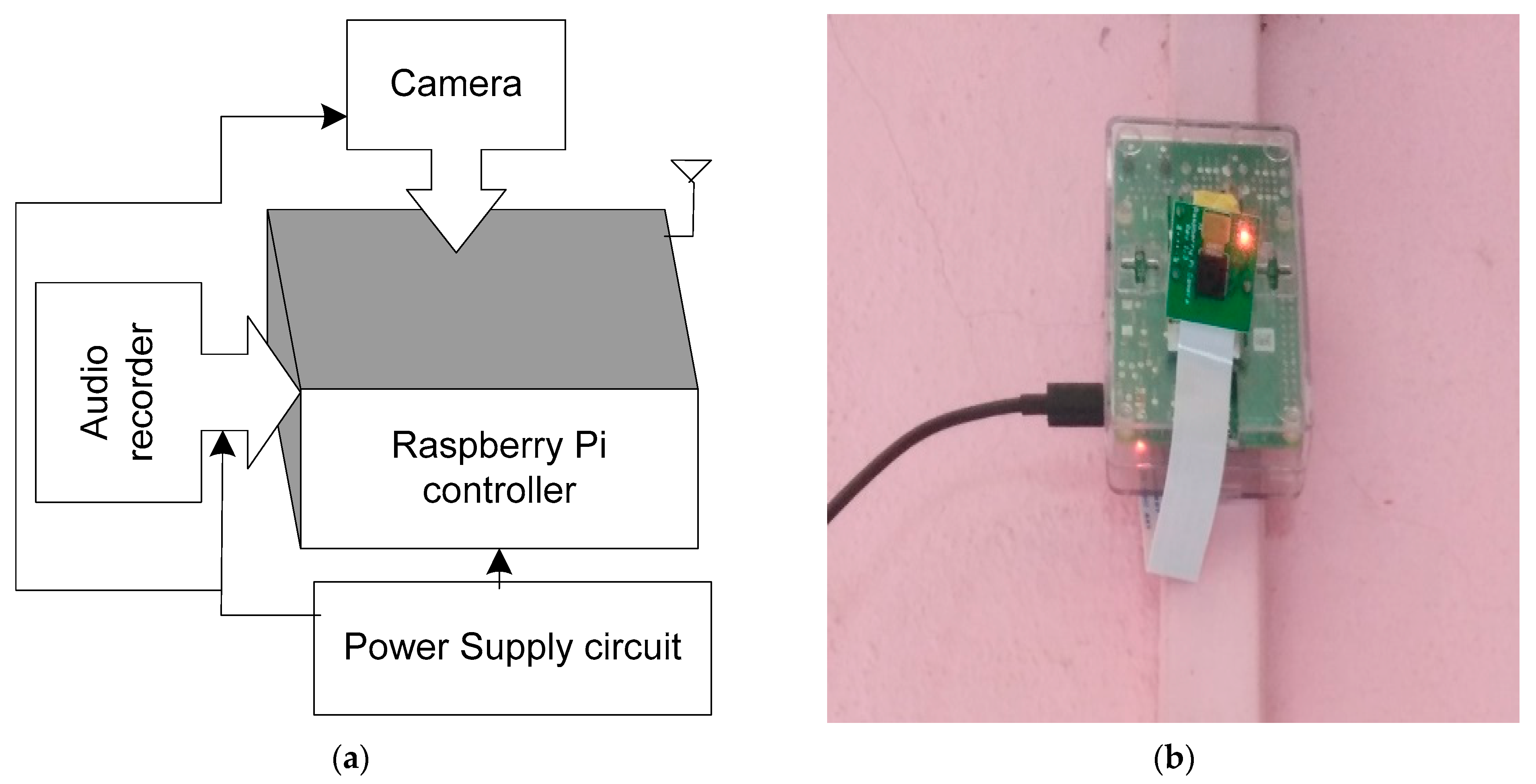
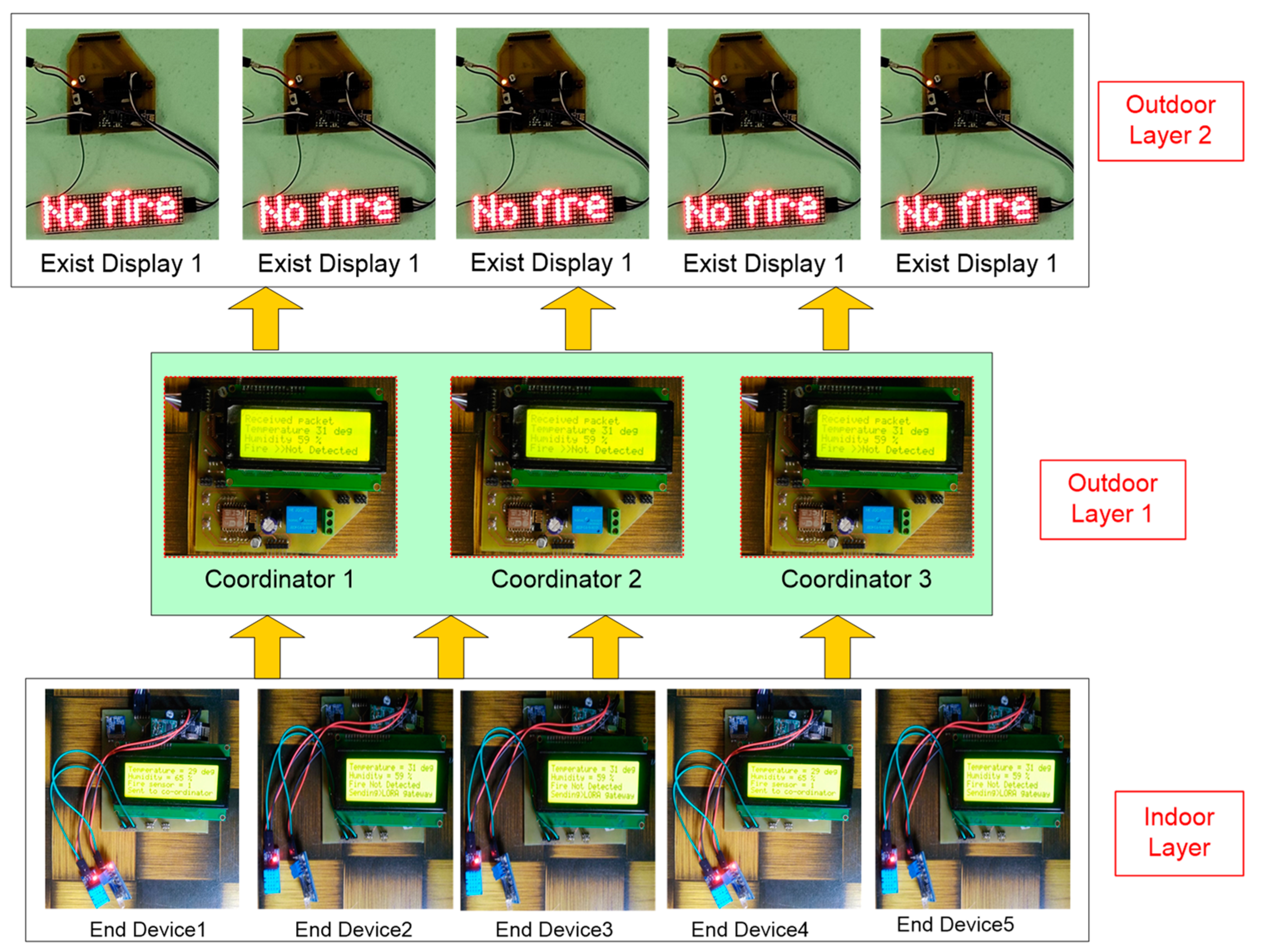
  • In this study, a hybrid architecture was proposed and implemented to complete fire monitoring of buildings. The hybrid architecture integrates multiple systems such as a real-time vision-node for people estimation and smoke detection, an evacuation path display with the shortest algorithm, real-time monitoring of the building-related fire on the cloud server, and control of the water sprinklers through real-time sensor data.
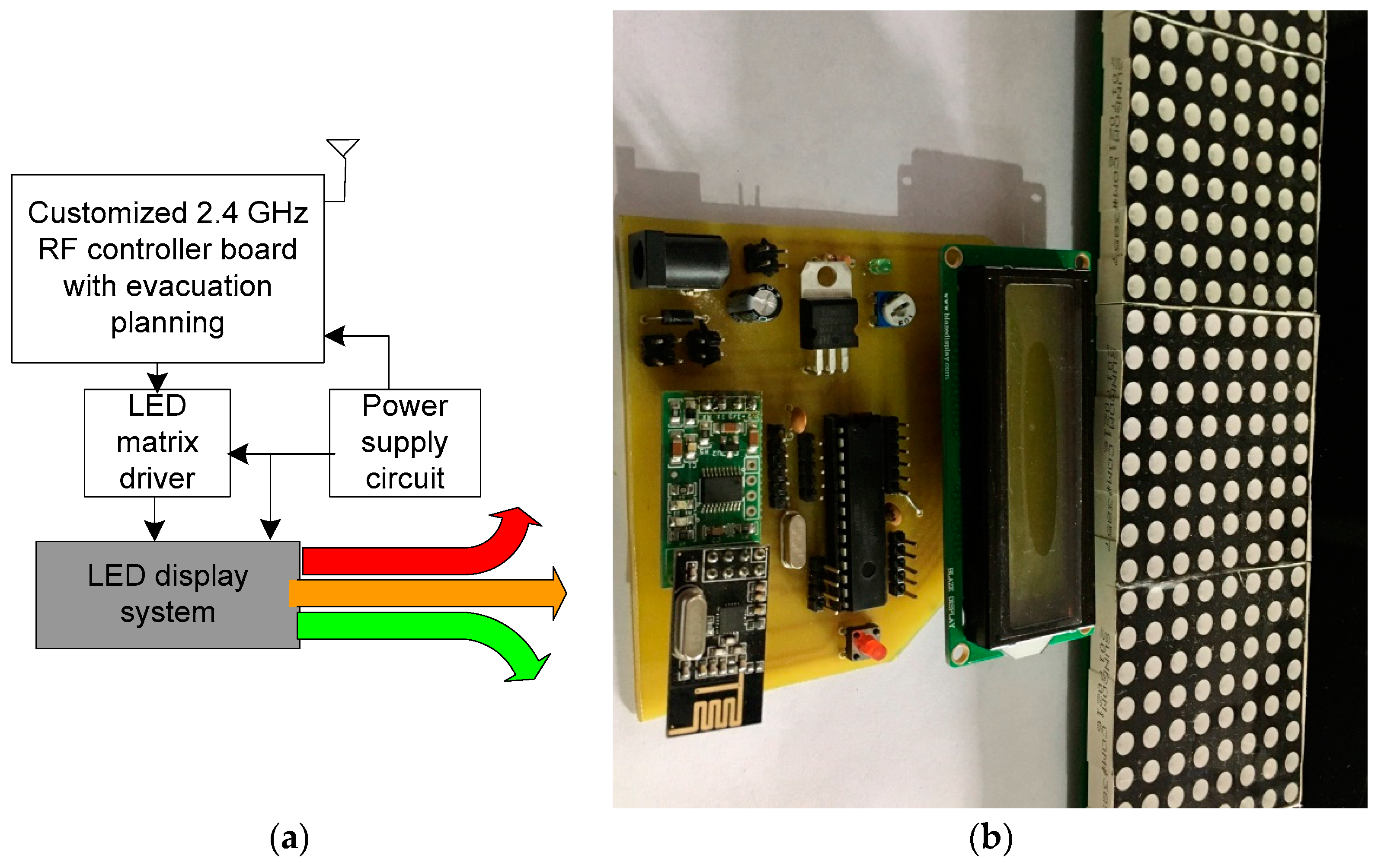
  • Customized hardware is realized for real-time implementation with 2.4 GHz Zigbee and 433 MHz LoRa communication with a node mapping feature.
  • A simulation of 2.4 GHz Zigbee and 433 MHz LoRa is carried out to analyze the behavior of network parameters.
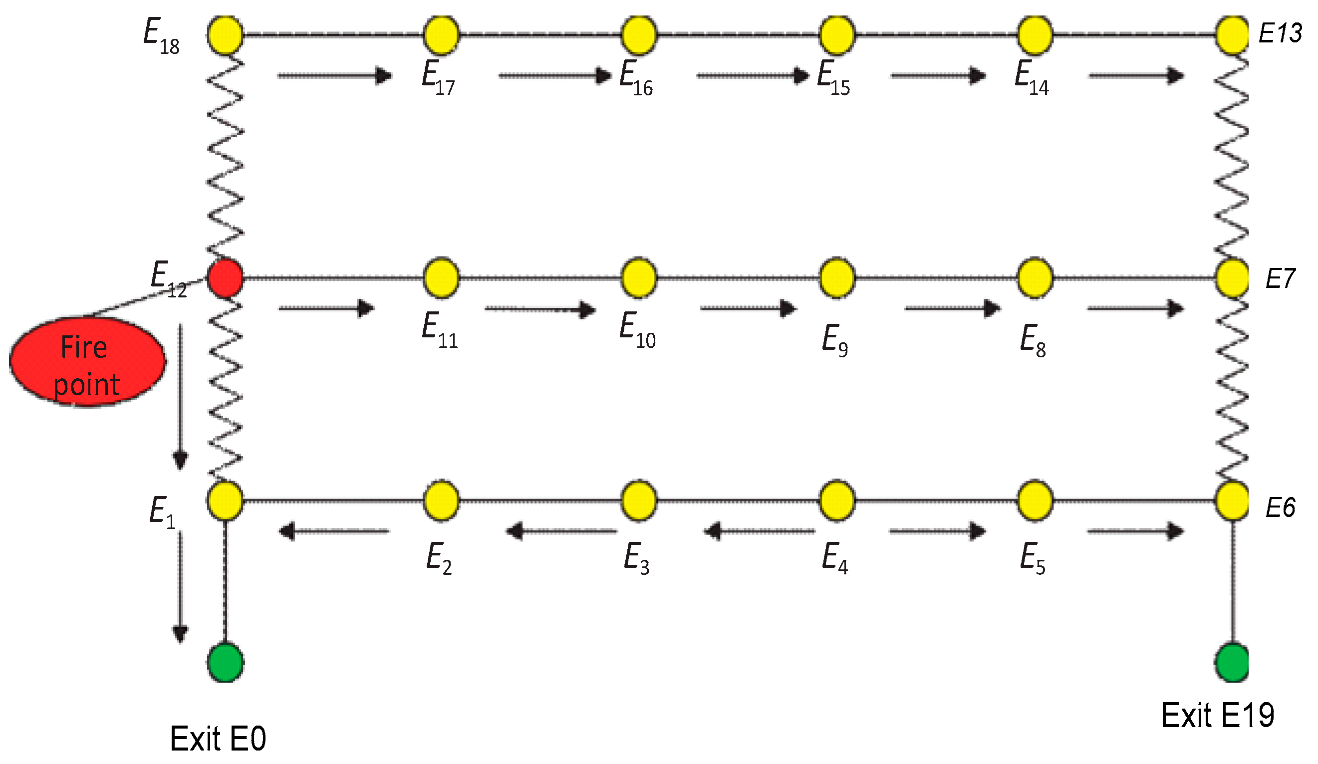
  • The shortest path algorithm logged in the evacuation display controller shows the fire exit path based on sensor data received from the end devices.
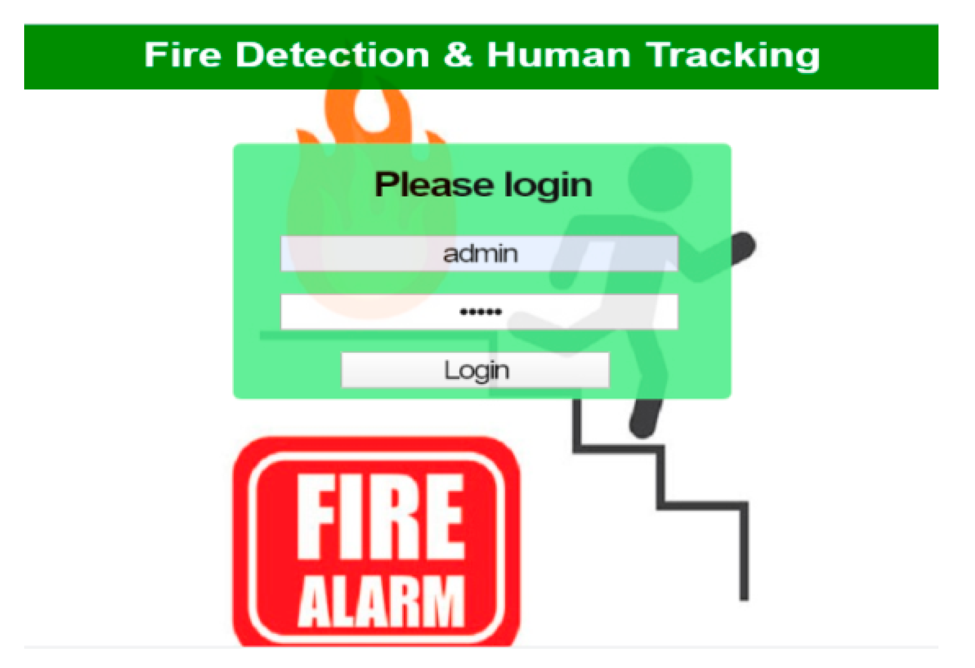
  • The vision-based system with a web application also shows real-time visuals for fire status and people detection.
The structure of the paper is as follows: Section 2 covers the literature review. Section 3 covers the overview of LoRa and Zigbee communication. Section 4 covers the proposed architecture. Section 5 covers the hardware design of the detection end device, evacuation path display controller, safety operation controller, and gateway. Section 6 covers the simulation analysis of Zigbee and LoRa. Section 7 covers the experimental results. Finally, the article concludes.

2. Literature Review

The real-time monitoring and detection of a fire are crucial for enhancing the fire management system. Moreover, during a fire accident, an evacuation path is necessary for the people to move safely out of the fire building. In this section, we discuss the previous studies that focused on implementing distinct techniques and systems for fire detection and an evacuation path. The classic method is widespread and essentially relies on prior evacuation warnings or human assistance in the event of an evacuation scenario; however, the lack of important information such as the safest exit location can be catastrophic [18]. An intelligent evacuation system is the latest approach to a more systematic and simultaneous management of crowds in an emergency [19,20]. A mobile terminal-based Intelligent Fire-fighting system was proposed to prevent urban disaster and for emergency management of a large public building during emergency evacuation [21]. Early detection of fires in houses using a wireless sensor network (WSN) and GSM for overcoming false alarms has also been proposed [22]. To mitigate the existing problem of automation and central management of building hardware and control services, a low-cost IoT-based evacuation Service was implemented for real-life situations of Building Automation System (BAS) applications [23].
An intelligent fire defense guidance system using IoT technology for detecting the fire event and also providing a real-time safe path for exit was proposed [24]. An intelligent fire prevention and alarm system using ZigBee was proposed for fire safety and management of cultural relics in China [25]. The main focus of the paper was to determine the position of the user in the building and to visualize a 3D model of the building combined with visual evacuation along with instructions on smartphones [26]. A fire warning along with a multi-door control system using Field programmable gate array (FPGA) to provide the information of floor where the fire occurred was developed, which results in an improvement in evacuation [27]. The combination of digital signage and image reorganization techniques was also used to guide people in an emergency through a safe route [28].
An intelligent real-time evacuation guidance system was proposed along with field verification for indoor evacuation and guidance [29]. A real-time evaluation system along with a safe evacuation route was provided through the integration of a wireless sensor network (WSN) and radio identification (RFID) [30]. A cyber-physical systems method is used as a real-time emergency evacuation signage guidance system to direct occupants to safe and quick evacuation routes while taking into account fire source location and development patterns, as well as human traffic flow trends, in real time [31]. A real-time fire evacuation guidance system was proposed, which provides virtual reality using tools such as a building information model (BIM) [32]. A cloud-based rescue worker interface (RWI) was proposed to obtain information on the density of people in a building, the flow of fire, and the position of remaining wardens [33].
The real-time evacuation path planning technique was proposed for high-rise buildings during an emergency, and this system was a combination of real-time data acquisition, calculations of risk distribution, and formulation of an evacuation path [34]. Integration of RFID techniques and Cloud technology were used to build fire evacuation systems with a mobile phone terminal [35]. An evacuation system was proposed using Geographic Information Systems (GIS), IoT to improve the evacuation efficiency was used to obtain information about the building, and the evacuation path was estimated using MATLAB [36]. An IoT-based system was proposed for identifying the number of people in a building in a fire emergency with motion detection [37]. An agent-based emergency evacuation and guidance system were implemented for determining the automatic evacuation guidance plan [38].
A system was designed based on the Internet of Things (IoT), which uses a mobile cloud computing platform. Further, the experimental results showed that the Crowd Lives Oriented Track and Help Optimization system (CLOTHO) could effectively help to improve the convergence rate, reduce evacuation time, and the route length [39]. An intelligent evacuation guidance system was proposed for guiding people to safety, and it was based on WSN, RFID, an IP camera, and image recognition along with digital signage [40]. A cloud-based smart evacuation system that estimated important information from multiple sources in real-time was developed. Integration of cloud and IoT-based systems has been proposed for the estimation of real-time evacuation paths during an emergency [41]. An intelligent evacuation route guidance system used Wireless Sensor Networks and digital signage for predicting safe routes during an emergency. This system used a wireless sensor network to monitor environmental conditions, and algorithms were used to estimate safe evacuation paths, which also trigger digital signage systems for safe evacuation routes [42]. An IoT technology-based emergency fire detection system framework was proposed and also provided the real-time information of human presence and the air quality in the vicinity of the fire location [43].
An intelligent integrated fire rescue system, using wireless sensors and visual guidance, was implemented to obtain the information on real-time fire status, alarming, and guidance in evacuation [44]. An intelligent smoke detector system based on LoRa and indoor positioning to achieve low cost and high maneuverability was developed [45]. A LoRa based wireless security alarm system was proposed, where the A star-shaped network topology was preferred for long-distance communication with an alarm system [46].
A geospatial data extraction (SPDA) approach was used to develop artificial intelligence modules for fire sensors to improve fire detection capabilities, and intelligent spaces provided reliable fire alarm detection, effective fire suppression, and adaptive evacuation strategies for passengers, increasing evacuees’ chances of surviving building fires [47].
An intelligent fire detection system can predict the fire situation based on artificial intelligence technology and gas and temperature data collected from the fire scene through IoT devices [48].
From the literature review, it is concluded that a fire evacuation system requires an independent system that can display an evacuation path during an emergency. Moreover, the implementation of a hybrid communication protocol is required to implement a real-time system with IoT in fire evacuation.

3. Overview of LoRa and Zigbee

In this section, we present the LoRa and Zigbee technology with its basic architecture. Moreover, the packet structure of LoRa is presented in this section.

3.1. LoRa

LoRa is Long Range, low power wireless, a low-data-rate communication protocol for building an IoT network developed by Cycleo of Grenoble, France. LoRa uses license-free subgigahertz radio frequency bands [49] It provides long-range transmissions (1–15 km) with low power consumption. It enables the communication between remote sensors and gateways connected to the network Server and Application Servers. The LoRa network is based on a star topology in which end nodes send messages to multiple gateways, which further communicate with the network server [50]. Multiple gateways can receive the message sent by the end node as there is no dedicated linkage between the end node and gateway. Gateways and network servers are connected through proper internet protocol (IP), as shown in the LoRa basic architecture in Figure 1.
End devices can send their small amount of data over a long range with low frequencies. The end nodes consist of sensors, controllers, converters, etc., and these nodes are devices embedded with LoRa chips. LoRa Gateway: The gateway receives the communications from the LoRa endpoints and then transfers them onto the backhaul system. Typically, the gateways and network servers are connected via some backhaul (cellular, Wi-Fi, Ethernet, or satellite). The LoRa gateway receives data from the end nodes and sends them to the network server. A LoRaWAN contains a multitude of gateways with each possibly receiving and sending the same data.
Network Server: The network server has all the intelligence. It filters the duplicate packets from different gateways, completes security checks, and sends ACKs to the gateways. It is responsible for rejecting and scanning redundant data and security checks. Application Server: It is an end server where data sent by the end device are processed and necessary action taken. The Application can typically be built over IoT platforms such as AWS IoT using Lambda, DynamoDb, or S3 services.
The frame structure of three different layers of LoRa architecture namely the physical layer, MAC layer, and application layer are as follows, and the frame structure is shown in Figure 2.
The physical layer defines the signal that is transmitted by LoRa modules and devices. On the physical layer, a frame starts with a preamble. The preamble defines the packet modulation scheme. The preamble is preceded by a 20-bit long header and header CRC, payload, and payload CRC. The MAC layer consists of a MAC Header, a MAC Payload, and a Message Integrity Code (MIC). The complete MAC Header and MAC Payload portion is utilized to calculate the MIC value with a network session key (Nwk_SKey). The MIC value avoids the falsification of messages and validates the end node. Application Layer and its Packet: The application layer handles the MAC layer, and it consists of a Frame Header, Frame Payload, and Frame Port. The Frame Port value is defined as reliant on the application type. The Frame Payload value is encrypted with an application session key (App_SKey) based on the AES 128 algorithm.

3.2. Zigbee

Zigbee is a low-cost, low-power wireless IoT network technology that was designed as an open worldwide standard. The IEEE 802.15.4 physical radio specification underpins the Zigbee standard, which runs in unlicensed bands such as 2.4 GHz, 900 MHz, and 868 MHz. Due to the benefits of Zigbee technology, such as low cost and low power operating modes and topologies, this short-range communication technology is best suited for a variety of applications as compared to other proprietary communications, such as Bluetooth and Wi-Fi as shown in Figure 3.
The Zigbee protocol architecture, as shown in Figure 4, is made up of a stack of levels, with physical and MAC levels defining IEEE 802.15.4 and Zigbee’s network and application levels completing the protocol.
The physical layer (PHY) deals with various parameters such as output power, several channels, receive sensitivity, chirp modulation, channel rejection, and transmission. When transmitting and receiving signals, this layer performs modulation and demodulation processes. The majority of Zigbee applications run at a data rate of 250 kb/s in the 2.4 GHz ISM band. In the Medium access control (MAC), the radio frequency (RF) data exchanges between nearby devices are managed (point to point). Transmission retry and acknowledgment management, as well as collision avoidance strategies, are all part of the MAC (CSMA-CA). The network layer supervises all network-related operations. Routing features are added, allowing RF data packets to travel via numerous devices (many hops) on their way from source to destination (peer to peer).

4. Proposed Architecture

IoT is an emerging technology that enhances every area with its real-time monitoring application from any remote location. Moreover, the advanced and robust wireless communication technologies meet the requirement of IoT. In fire safety, the significance of establishing a real-time evacuation path is possible with a personal area network (LAN) and wide area network (WAN) for overcoming the network connectivity in terms of cost, energy consumption, and license band. With this advantage, in this study, a novel and hybrid IoT-enabled architecture based on 2.4 GHz Zigbee and LoRa communication protocol is created and is shown in Figure 5.
The hybrid architecture is the amalgamation of five different components namely end device, evacuation path display controller, safety operation controller, vision node, and gateway. The end device and vision node are the primary devices that are deployed in the building for sensing parameters including smoke, fire, temperature, and gas through the attached sensors and camera module. The end device is embedded with a 2.4 GHz Zigbee and LoRa RF module. The 2.4 GHz Zigbee enables “N’ number end devices to transmit the sensory data to the evacuation path display controller and safety operation controller. Here, the safety operation controller analyzes the data, and in the case of a fire, it immediately triggers the sprinkler system at the place where the fire was initiated. The evacuation path display controller also analyzes the sensory data received from the end device and provides the visualization of the safe evacuation path for the people in the building.
Moreover, to enhance the detection of fire accidents, a vision node is also positioned at a place near the end device. The vision node is loaded with an analytic model, which can distinguish the fire accurately, and it communicates the visuals to the local server and cloud server through internet connectivity. As discussed earlier, the end device is embedded with a LoRa module, the LoRa module enables transmission of the sensor data to the gateway via LoRa communication. This gateway logs the sensory data into the cloud server via Wi-Fi. The cloud server records the sensory data and visual data to assist the fire authorities with continuous vision of the building fire system.

5. Hardware Design

In this section, we discuss the requirement of customizing the hardware for the fire and safety application in the building. The customization enables the researcher to design and develop the hardware according to the requirement and application. Generally, to design any hardware node, the main component to be examined is energy consumption. The energy consumption is analyzed because the hardware nodes are deployed in the outdoor environment where they are dependent on a battery. So, each component that is integrated onto the hardware board needs to consume low energy during active and sleep states. To achieve this target, the first component we selected was the 2.4 GHz-based Zigbee and LoRa communication protocol, as both consume low energy during transmission of data. Another major component is the computing unit; the computing unit processes the sensory data from the embedded sensors. As the complexity of processing the data is low, we chose the ATMEGA328P controller unit. Moreover, the components chosen for building the hardware have a different operating voltage, so to supply the appropriate voltage, we need a power convertor. A detailed description of the four components that are integrated with the proposed system follows.
The end device senses the parameters of fire including smoke, fire, temperature, and gas and communicates to the evacuation path display controller, safety operation controller with the 2.4 GHz based Zigbee, and to the gateway via LoRa, as shown in Figure 6a. Smoke and flame sensors are employed to sense smoke and fire. A gas sensor is integrated for detecting gas leakage, which can also cause a fire explosion in the building. All these sensors are integrated into the controller board, where the signal optimization is processed. The power supply circuit supplies the external power to the components presented in the node. Figure 6b presents the final hardware prototype of the end device, which visualizes the hardware that will be positioned in the building. A liquid crystal display (LCD) is integrated on the end device hardware to display the sensor values.
The evacuation light-emitting diode (LED) display is used to a display safe route during a fire emergency. It will guide people though the safe exit path by displaying the appropriate direction. Figure 7a presents the block diagram, which provides the details of interfacing the different components to the controller board. To visualize the safe path, a matrix LED is integrated along with drivers. Moreover, it is integrated with 2.4 GHz-based Zigbee communication to receive the sensory data from the end device. The received sensor data are analyzed, and if a fire is detected, it displays a safe evacuation path on the LED matrix display. The hardware prototype of the evacuation LED display is illustrated in Figure 7b.
The vision node was developed based on Raspberry Pi with a Pi camera, and it is shown in Figure 8a,b. A properly designed vision node assists to monitor the realtime condition of the environment during fire accidents. It works seamlessly even in power failure as it operates via battery. It also helps to visualize the density of people to be evacuated.
The safety operation controller acts according to the sensor data received from the end device regarding fire, smoke, and gas, and the block diagram of the safety operation controller is shown in Figure 9a. This controls the sensor value, if the received sensor value signals a fire, then the sprinkler connecting to the controller is switched on. A fire sprinkler system is an active type of fire protection system that discharges water in the event of a fire. Automatic sprinkler systems are often considered the most significant component of a building’s fire protection strategy. The hardware prototype of the safety operation controller is shown in Figure 9b, where the blue component is a driver for switching on the sprinkler.
The LoRa Gateway is employed to communicate the real-time data of the end device to the cloud server. This gateway combines the LoRa and Wi-Fi module to establish the communication between the end devices and cloud server. Moreover, the gateway is integrating with an alarm to alert the fire authorities to the accident. The block diagram in Figure 10a presents the interface of the components with the control unit. As discussed earlier, the gateway is embedded with two different communication protocols, and it can be visualized in the PCB layout in the hardware prototype that is presented in Figure 10b.

6. Simulation

In this section, we present the simulation of the ZigBee and LoRa networks. Here, we changed certain parameters to examine the network behavior of both networks. An OPNET simulator was utilized to perform the simulation. The simulation of the Zigbee and LoRa network occurred as follows:

6.1. Zigbee

The simulation of the Zigbee network for the proposed system was carried out and performance analysis concerning various parameters was calculated. The Riverbed simulation model was used to realize the Zigbee framework, as depicted in Figure 11. It was tested based on start topology and was configured as per the parameters stated in Table 1. In this case, we used various performance indicators such as sent and received traffic statistics, the end-to-end delay between layers, the packet delivery ratio, retransmission attempts, and throughput over the channels.
Figure 12 shows the simulation result of the packets received by the nodes in the ZigBee network. This simulation was carried out over the timeline. The packets were received at the speed of 900 bits/s throughout the timeline. Figure 13 illustrates the packet sent by the sender node to the target node over a timeline. It was configured to receive the data at a speed of 450 bit/s. Based on our analysis, we received a PDR of about 0.80. In another way, we can say that nodes established communication with 80% accuracy.

6.1.1. End-to-End Delay

End-to-end delay refers to the overall time used by the packet generation and node transfer processes. It is made up of the total time spent on route finding, queuing, propagation, and transferring. As shown in Figure 14, end to end delay analysis was carried out over the timeline. The maximum end-to-end delay was 0.016 s found at 20 min and the minimum end-to-end delay was 0.008 s found at 11 min.

6.1.2. Throughput

The pace at which data are successfully transmitted from a source node to a destination node is referred to as throughput. Here, the highest throughput reached 58 kbps at 7 min on the timeline axis of simulation, and the minimum level throughput was 53 kbps at many places. Figure 15 shows the average throughput was 53 kbps.

6.1.3. Retransmission Attempts

Retransmission attempts are the overall amount of retransmission tries made by all 802.15.4 MACs in the network until a packet is successfully sent or the attempt limit is reached. Figure 16 illustrates the retransmission attempts were 0.5 packets for the simulation period of 30 min.

6.2. LoRa

The LoRa communication protocol has significant parameters that were utilized to estimate the performance of the network. The performance of the network was estimated by adjusting certain parameters including the spreading factor (SF), bandwidth (BW), and code rate (CR). The analysis of bit rate, link budget, and LoRa sensitivity are presented below.

6.2.1. Time on Air (ToA)
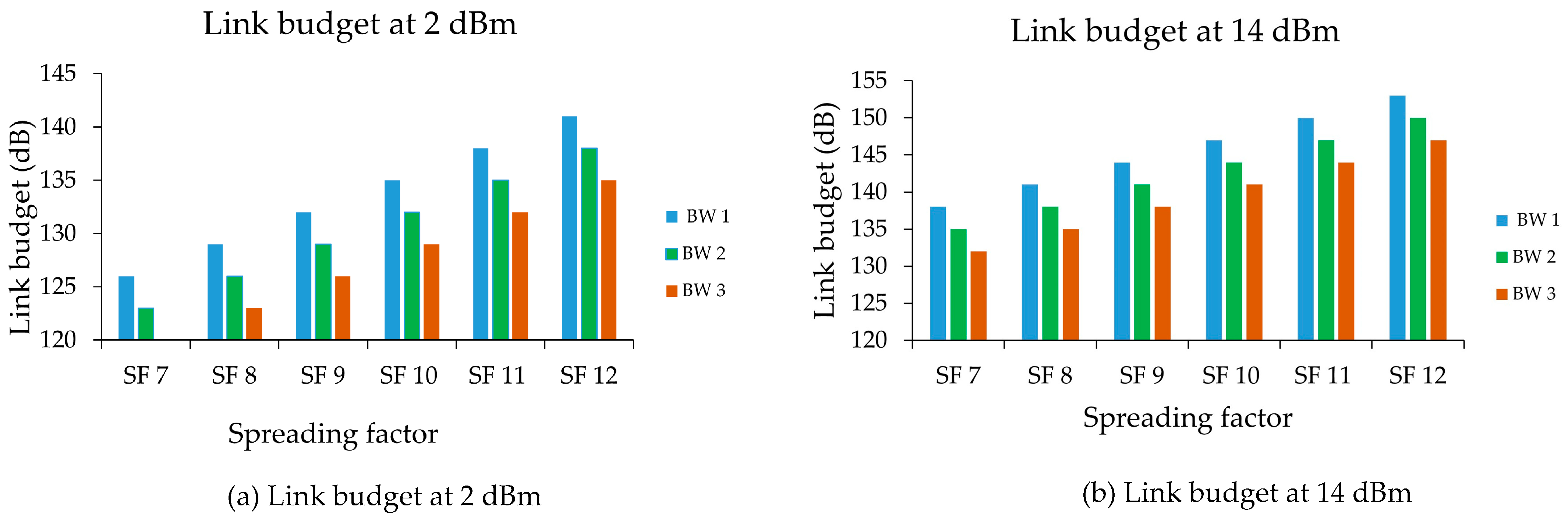
To compute the ToA in this study, we utilized the following parameters namely payload = 28 bytes, preamble = 8 symbols, CF = 433 MHz, and Tx power = 14 dBm. Here, we included three distinct BW: 125 kHz, 250 kHz, and 500 kHz, SF 7–SF 12, and CR from 1 to 4. ToA was calculated at SF7, SF12, and CR of 1,2,3,4. The graph illustrates that the ToA rose when the SF moved from 7 to 12 and ToA was decreased by half when the bandwidth rose from 125 kHz to 500 kHz.
Figure 17 illustrates the ToA for the payload size of 28 bytes. The ToA graph in different CR indicates that after the SF 9 the ToA began to rise. The ToA was high for the 125 kHz BW of all three BW, while the 500 kHz BW was low. CR is shown to be exactly related to the growth of the ToA, e.g., at CR 1, BW 1 ToA was 56.58 ms, and the CR 4 ToA was 78.08 ms at the same BW1.

6.2.2. Link Budget

The sum of losses and benefits is the link budget or power received. For calculation of the link budget, the three BW were 125 kHz, 250 kHz, and 500 kHz, and SF 7 and SF 12. The bandwidth is shown as BW1, BW2, and BW3 (125 kHz) (500 kHz). The transmission power was 2 dBm and 14 dBm. The rise in Tx led to a rise in connection budget, as can be seen in Figure 18. Any increase in the SF increased the budget for the connection. The connecting budget reached a maximum dBm at SF 12 at 14 dBm for 125 kHz. Low dBm for 500 kHz was measured at SF7 of 2 dBm from the link budget. High Tx power and low BW power are appropriate parameters for attaining a high link budget.

7. Experimental Results

This section covers the deployment of the proposed hybrid architecture for real-time monitoring of fire and safety. Here, we deployed the end device in the outdoor environment to sense the parameters of smoke, flame, gas, and temperature. The evacuation path display controller, safety operation controller, and vision node were also deployed in a real-time environment to evaluate the performance of the proposed architecture. Figure 19 illustrates the deployment of the completed system in a real-time environment. To visualize the sensor data on the cloud server, we utilized a cloud-based Blynk server and application.

7.1. Realtime Implementation

In a real-time environment, we deployed the end device at different locations of the building. The evacuation path display controller and safety operation controller were also deployed at a different position near the end device to receive the sensor data through 2.4 GHz Zigbee communication. Here, we integrated the flame sensor and DHT sensor with the end device to sense the fire, temperature, and humidity in the indoor building environment. When the data collection node sends a signal of fire breakage, the vision node also sends an information log verifying the same, which is used by the coordinator as an extra layer of information to be used for correlating and examining the current status and preventing any false alarm. The end device with the assistance of LoRa communication transmits the sensor data to the gateway. As the gateway is integrated with the LoRa and Wi-Fi module, it logs the sensor data to the cloud server, i.e., Blynk server. Moreover, Figure 19 clearly illustrates the specifications such as the controller and communication protocol of the hardware that were deployed in the indoor layer and outdoor layer. The Blynk dashboard displays the sensor value received through LoRa communication. After the deployment of all the hardware in real-time, we switched on all the nodes and tested the performance of the nodes in terms of sensing fire, temperature, and visual data in the building. Moreover, communicating this data to the gateway and cloud server was also evaluated in this study.
In Figure 20, the working of the hardware device is visualized, where the end device communicated the sensor data of fire status, temperature, and humidity. As discussed earlier, the end device is the amalgamation of LoRa and 2.4 GHz based Zigbee. The end device communicates the sensor data to the evacuation path display controller through 2.4 GHz based Zigbee and to the gateway via LoRa. The LCD in the end device, evacuation path display controller, and gateway visualize the temperature, humidity, and fire status data. The gateway logs the sensor data on the Blynk server through internet connectivity. Figure 20 presents the Blynk dashboard that visualizes the fire status, temperature, and humidity data. The two different results are visualized in the Blynk dashboard.
In Figure 21a, the dashboard shows the temperature value as 33 °C, the humidity level as 66, and fire as not detected. Figure 21b illustrates another instance, where fire is detected, along with a temperature of 51 °C and a humidity level of 89. This clearly illustrates that the proposed architecture can visualize the real-time sensor data of the building related to fire.

7.1.1. Vision Node

Moreover, we present the results obtained through the vision node. The main function of the vision node is to enhance fire detection accurately. Here, to obtain real-time data from vision nodes we built a web application that was hosted on the local server. The login window of the application is shown in Figure 22. Only authorized personnel with proper credentials can access the entire system. To trigger the vision node, we need to log on to the web portal. A successful log-on will then trigger all the vision nodes deployed inside the building connected through the internet. Once they connect successfully, the vision nodes start streaming live visuals along with estimated data such as fire detection status and the people count, as shown in Figure 23.
Figure 24 illustrates the working of the vision node with the web application. After completion of login, a request is sent to the vision node. The vision node starts streaming the visual data, where the visuals are captured through the input camera. The input camera frame can evaluate whether the fire is detected or not. Moreover, the people count is also processed and the result is communicated to the web application through internet protocol (IP). Finally, the result is visualized on the web application.

7.1.2. Evacuation Path

This section describes the building evacuation decision-making model implemented under the 2005 Indian National Building Standards Act and the 2005 Fire Safety Act. This decision model is based on the Dijkstra algorithm [51], which is an improved algorithm that is applied for the shortest route in a building (Figure 25). This approach assists in finding the shortest path between the specified source node and all other nodes in the graph. It can also be used to find the shortest path from a single node to a single target node. The process will stop as soon as the shortest path to the target node is established. Dijkstra’s algorithm uses fully ordered labels that are positive integers or real numbers. The steps of Dijkstra’s algorithm to find the shortest path from a single source node on the graph to all other nodes are show below.
Steps of Dijkstra’s Algorithm to Find the Shortest Path.
  • Make a set called sptSet (shortest path tree set) to keep track of the vertices in the shortest-path tree, i.e., those whose minimal distance from the source is calculated and completed. This set is initially empty.
  • Assign a distance value to each of the input graph’s vertices. All distance values should be set to INFINITE. Assign the source vertex a distance value of 0 to ensure that it is chosen first.
  • Because sptSet does not contain all vertices.
    • Choose a vertex u that is not in sptSet and has a minimum distance value.
    • Add u to the sptSet.
    • Update the distance between all of u’s adjacent vertices. Iterate through all nearby vertices to update the distance values. If the total distance value of u (from source) and the weight of edge u-v is less than the distance value of v for each neighboring vertex v, then update the distance value of v.
The equivalent diagram of a building is also shown in Figure 26. Here, the rooms are replaced with bubbles, the stairs are replaced with jagged lines, and the straight lines are replaced with straight lines. Each entity acts as a node called {E0, E1, …, E19}. In this case, {E0 and E19} are the target nodes, {E1, E2, …, E18} are the source nodes. Equivalent lengths of canals are not the same, due to different factors in the ease of evacuation routes under different road traffic conditions. As the equivalent distance increases, the weight of the route in the weighted graph increases.
In the absence of a fire hazard, after using the improved Dijkstra algorithm the shortest path to exit E0 from relay node E18 is {E18, E12, E1, E0}. The middle node is E1, E12, the length is 14 m. The shortest path to leave E19 from transit node E18 is {E18, E17, E16, E15, E14, E13, E7, E6, E19} and the intermediate nodes are E6, E7, E13, E14, E15, E16, E17, the length is 51.5 m. In this case, since the distance to the destination node, E0 from node E18 is relatively less, it has to choose output E0 as its output, and the final path output is {E18, E12, E1, E0}. Based on this analysis, the shortest paths from each source node to the destination node are shown as shown in Table 2.
To improve overall safety and evacuation efficiency, the subsequent fire alarm should not modify the completed emergency evacuation route directions, as changes in evacuation direction generate panic. If a source node’s sensor nodes detect a fire emergency and the source node is closest to transit node E12, the source node is activated. Evacuees are unable to pick channel E18, E12 because it becomes extremely contaminated by a smoke stream in a relatively short period. Figure 27 depicts the analogous diagram of a structure with nodes during a fire emergency. Because the computed evacuation route based on the shortest distance is now inaccurate, it cannot be utilized as a guide for the safety of the evacuation plan.
To overcome this issue, an updated Dijkstra method is proposed, and evacuees can use it to determine the ideal path of escape output respective transmission nodes, as indicated in Table 3.
The exit routes for nodes E10, E11, E16, E17, and E18 vary compared to the exit path when there is no risk of fire. For example, the shortest route from node E18 to the exit is shifted from the original shortest route (i.e., E18, E12, E1, E0) to the optimal route (i.e., E18, E17, E16, E15, E14, E13, E7, E6, E19) because the path passes node E12, which is close to the fire spot. The optimal evacuation route based on the improved algorithm has a longer walking distance than the shortest route, but it is safer and allows you to evacuate safely while avoiding fires caused by unexpected damage.
During the actual evacuation, one of the evacuation routes on the personnel congested phenomenon can lead to an extension of the evacuation time. The best strategy is to redirect some of the crowd to a safe and relatively open road, as this will make it easier to use an alternative path and ensure a smooth evacuation of everyone to the exit safely. The distance from all given nodes to the exit is calculated using coordinated devices that collect data from the sensors of all wireless nodes and calculate the optimal exit path using the improved algorithm as discussed. The evacuation information calculated by the dispatching node is then linked to the dynamic output display to indicate that the lights are flashing and to confirm that the correct direction is being generated. The presented decision model is saved in the output display document. Initially, sensor nodes collect environmental data of the deployed location and send them wirelessly to dispatching nodes. The coordinator node then makes a decision based on the model as discussed and operates the output screen.
When there is no fire alarm signal from the end devices, the coordinator will send a command to the display module to display the normal direction or announce that there is no fire. The operating model of the evacuation guidance system in the absence of fire is shown in Figure 28. If there is a fire detection signal from the end devices, the coordinator sends a command to the output display module to display the direction according to the decision pattern to provide an optimal and safe exit for evacuees. The operating model of the exit guidance system is shown in Figure 29.
Table 4 illustrates the comparative analysis of the proposed system with previous studies implemented for building fire evacuation paths. The comparative analysis was performed based on certain parameters, namely: hardware, data collecting device, network simulation analysis, communication technology, and user interface. From the comparative analysis, it is concluded that the proposed system is superior to the previous studies in terms of implementing fire detection with customized hardware based on an Atmega 328P microcontroller, 2.4 GHz, and LoRa communication. Moreover, a hybrid architecture is proposed for establishing IoT enabled evacuation system. Network simulation of Zigbee and evaluation metrics of LoRa were performed in this study. The proposed architecture was realized with the Blynk cloud server application, where the hardware data were logged from the hardware into the cloud server. The majority of the study implemented evacuation paths on the simulation platform and limited studies have utilized hardware for executing the evacuation system. Dijkstra’s algorithm was tested and recorded on the exit display hardware to implement the evacuation path in real-time.

8. Conclusions

Currently, fire monitoring and fire safety are crucial in buildings to avoid damage and loss. Due to advances in sensor technology and wireless communication, real-time monitoring implementations are now widespread in every application. With this motivation, we implemented a system that monitors the fire status of buildings such as real-time sensing data, predicts safe and optimal evacuation paths, and actuates sprinkler systems to mitigate fire flow. The proposed system was implemented in real-time with customized hardware integrated with 2.4 GHz Zigbee and 433 MHz LoRa communication. In addition to this, in this study, we simulated Zigbee and LoRa networks to estimate network parameters during transmission. In this study, Dijkstra’s shortest path algorithm was incorporated to implement evacuation route display control that provided the shortest evacuation route in the event of a fire. The system also logged the sensor data from the end devices to the cloud server through LoRa and Wi-Fi communication.

Author Contributions

R.S., A.G. and G.S.B. contributed to conception and manuscript writing; A.S.A. and S.S.A. examined and supervised this research and outcomes; M.R. and S.V.A. revised and polished the manuscript. All authors have read and agreed to the published version of the manuscript.

Funding

This research was supported by Taif University Research Supporting Project number (TURSP-2020/311), Taif University, Taif, Saudi Arabia.

Institutional Review Board Statement

Not applicable.

Informed Consent Statement

Not applicable.

Data Availability Statement

Not applicable.

Conflicts of Interest

The authors declare no conflict of interest.

References

  1. Ronchi, E.; Nilsson, D. Fire evacuation in high-rise buildings: A review of human behaviour and modelling research. Fire Sci. Rev. 2013, 2, 1–21. [Google Scholar] [CrossRef] [Green Version]
  2. Murali, L.G.; Vijayalakshmi, M.M. Fire accidents in buildings–Case studies. Int. J. Eng. Trends Technol. 2014, 11, 178–184. [Google Scholar] [CrossRef]
  3. Birajdar, G.S.; Singh, R.; Gehlot, A.; Thakur, A.K. Development in building fire detection and evacuation system-a comprehensive review. Int. J. Electr. Comput. Eng. (IJECE) 2020, 10, 6644–6654. [Google Scholar] [CrossRef]
  4. Han, D.; Lee, B. Flame and smoke detection method for early real-time detection of a tunnel fire. Fire Saf. J. 2009, 44, 951–961. [Google Scholar] [CrossRef]
  5. Swain, M.; Zimon, D.; Singh, R.; Hashmi, M.F.; Rashid, M.; Hakak, S. LoRa-LBO: An Experimental Analysis of LoRa Link Budget Optimization in Custom Build IoT Test Bed for Agriculture 4.0. Agronomy 2021, 11, 820. [Google Scholar] [CrossRef]
  6. Gehlot, A.; Alshamrani, S.S.; Singh, R.; Rashid, M.; Akram, S.V.; AlGhamdi, A.S.; Albogamy, F.R. Internet of Things and Long-Range-Based Smart Lampposts for Illuminating Smart Cities. Sustainability 2021, 13, 6398. [Google Scholar] [CrossRef]
  7. al Rasyid, M.U.H.; Enda, D.; Saputra, F.A. Smart Home System for Fire Detection Monitoring Based on Wireless Sensor Network. In Proceedings of the 2019 International Electronics Symposium (IES), Surabaya, Indonesia, 27–28 September 2019; pp. 189–194. [Google Scholar]
  8. Singh, R.; Gehlot, A.; Thakur, A.K.; Swain, M.; Akram, S.V. Wireless Sensor Network with Power Management System for Water Level Regulation in Paddy Fields. Int. J. Innov. Technol. Explor. Eng. (IJITEE) 2020, 9, 1243–1246. [Google Scholar]
  9. Gehlot, A.; Singh, R.; Thakur, A.K.; Choudhury, S.; Das, P.K.; Gupta, K.V. Wireless Monitoring and Acquisition of Engine Noise Data Using IoT. Int. J. Eng. Appl. (IREA) 2020, 8, 215–222. [Google Scholar] [CrossRef]
  10. Moon, S.-R.; Cho, J.-H. Study on IoT-based Map Inside the Building and Fire Perception System. J. Digit. Converg. 2019, 17, 85–90. [Google Scholar]
  11. Singh, R.; Gehlot, A.; Akram, S.V.; Thakur, A.K.; Buddhi, D.; Das, P.K. Forest 4.0: Digitalization of forest using the Internet of Things (IoT). J. King Saud Univ.-Comput. Inf. Sci. 2021, 1–15. [Google Scholar] [CrossRef]
  12. Sendra, S.; García, L.; Lloret, J.; Bosch, I.; Vega-Rodríguez, R. LoRaWAN network for fire monitoring in rural environments. Electronics 2020, 9, 531. [Google Scholar] [CrossRef] [Green Version]
  13. Malik, P.K.; Sharma, R.; Singh, R.; Gehlot, A.; Satapathy, S.C.; Alnumay, W.S.; Pelusi, D.; Ghosh, U.; Nayak, J. Industrial Internet of Things and its applications in industry 4.0: State of the art. Comput. Commun. 2020, 166, 125–139. [Google Scholar] [CrossRef]
  14. Adeel, A.; Gogate, M.; Farooq, S.; Ieracitano, C.; Dashtipour, K.; Larijani, H.; Hussain, A. A survey on the role of wireless sensor networks and IoT in disaster management. In Geological Disaster Monitoring Based on Sensor Networks; Springer: Singapore, 2019; pp. 57–66. [Google Scholar]
  15. Akram, S.V.; Singh, R.; AlZain, M.A.; Gehlot, A.; Rashid, M.; Faragallah, O.S.; El-Shafai, W.; Prashar, D. Performance Analysis of IoT and Long-Range Radio-Based Sensor Node and Gateway Architecture for Solid Waste Management. Sensors 2021, 21, 2774. [Google Scholar] [CrossRef]
  16. Gehlot, A.; Singh, R.; Thakur, K.A.; Pandey, R. Design and Development of Wireless Fan Regulator using ZigBee Concept. Int. J. 2020, 9, 4189–4194. [Google Scholar] [CrossRef]
  17. Swain, M.; Hashmi, M.F.; Singh, R.; Hashmi, A.W. A cost-effective LoRa-based customized device for agriculture field monitoring and precision farming on IoT platform. Int. J. Commun. Syst. 2020, 36, e4632. [Google Scholar] [CrossRef]
  18. Bahamid, A.; Ibrahim, A.M.; Ibrahim, A.; Zahurin, I.Z.; Wahid, A.N. Intelligent robot-assisted evacuation: A review. In Journal of Physics: Conference Series; IOP Publishing: Coimbatore, India, 2020; Volume 1706, p. 012159. [Google Scholar]
  19. Zhang, Q.; Chen, T.; Lv, X.Z. New framework of intelligent evacuation system of buildings. Procedia Eng. 2014, 71, 397–402. [Google Scholar] [CrossRef] [Green Version]
  20. Ibrahim, A.M.; Venkat, I.; Subramanian, K.; Khader, A.T.; Wilde, P.D. Intelligent evacuation management systems: A review. ACM Trans. Intell. Syst. Technol. (TIST) 2016, 7, 1–27. [Google Scholar] [CrossRef]
  21. Huixian, J.; Shaoping, Z. Design of Intelligent Fire-Fighting System of a Big Public Building Emergency Evacuation Navigation System for Mobile Terminal. In Proceedings of the 2018 13th International Conference on Computer Science & Education (ICCSE), Colombo, Sri Lanka, 8–11 August 2018; pp. 1–6. [Google Scholar]
  22. Saeed, F.; Paul, A.; Rehman, A.; Hong, W.H.; Seo, H. IoT-based intelligent modeling of smart home environment for fire prevention and safety. J. Sens. Actuator Netw. 2018, 7, 11. [Google Scholar] [CrossRef] [Green Version]
  23. Gokceli, S.; Zhmurov, N.; Kurt, G.K.; Ors, B. IoT in action: Design and implementation of a building evacuation service. J. Comput. Netw. Commun. 2017, 2017, 1–13. [Google Scholar] [CrossRef]
  24. Majumder, S.; O’Neil, S.; Kennedy, R. Smart apparatus for fire evacuation—An IoT based fire emergency monitoring and evacuation system. In Proceedings of the 2017 IEEE MIT Undergraduate Research Technology Conference (URTC), Cambridge, MA, USA, 3–5 November 2017; pp. 1–4. [Google Scholar]
  25. Guan, Y.; Fang, Z.; Wang, T. Fire risk assessment and daily maintenance management of cultural relic buildings based on ZigBee technology. Procedia Eng. 2018, 211, 192–198. [Google Scholar] [CrossRef]
  26. Chittaro, L.; Nadalutti, D. A mobile RFID-based system for supporting evacuation of buildings. In International Workshop on Mobile Information Technology for Emergency Response; Springer: Berlin/Heidelberg, Germany, 2008; pp. 22–31. [Google Scholar]
  27. Angel, A.S.; Jayaparvathy, R. Design and implementation of an intelligent emergency evacuation system. In Proceedings of the 2017 International Conference on Computation of Power, Energy Information and Commuincation (ICCPEIC), Melmaruvathur, India, 22–23 March 2017; pp. 13–17. [Google Scholar]
  28. Yu, K.-M.; Yu, C.-S.; Lien, C.-C.; Cheng, S.-T.; Lei, M.-Y.; Hsu, H.-P.; Tsai, N. Intelligent evacuation system integrated with image recognition technology. In Proceedings of the 2015 8th International Conference on Ubi-Media Computing (UMEDIA), Colombo, Sri Lanka, 24–26 August 2015; pp. 23–28. [Google Scholar]
  29. Chung, N.-E.; Yu, K.-M.; Hsu, H.-P.; Cheng, S.-T.; Lien, C.-C.; Lei, M.-Y.; Tsai, N. An effectiveness study of an intelligent emergency evacuation system using field verification techniques. In Proceedings of the 2017 Sixth International Conference on Future Generation Communication Technologies (FGCT), Dublin, Ireland, 21–23 August 2017; pp. 1–6. [Google Scholar]
  30. Hsu, H.P.; Yu, K.M.; Chine, S.T.; Cheng, S.T.; Lei, M.Y.; Tsai, N. Emergency evacuation base on intelligent digital signage systems. In Proceedings of the 2014 7th International Conference on Ubi-Media Computing and Workshops, Ulaanbaatar, Mongolia, 12–14 July 2014; pp. 243–247. [Google Scholar]
  31. Zhang, J.; Issa, R.R.A.; Liu, R. A cyber-physical system approach for intelligent building emergency evacuation signage guidance. In Proceedings of the Construction Research Congress, New Orleans, LA, USA, 2–4 April 2018; pp. 535–541. [Google Scholar]
  32. Wang, B.; Li, H.; Rezgui, Y.; Bradley, A.; Ong, H.N. BIM based virtual environment for fire emergency evacuation. Sci. World J. 2014, 2014, 1–13. [Google Scholar] [CrossRef] [PubMed]
  33. Poy, H.M.; Duffy, B. A cloud-enabled building and fire emergency evacuation application. IEEE Cloud Comput. 2014, 1, 40–49. [Google Scholar] [CrossRef]
  34. Han, Z.; Weng, W.; Zhao, Q.; Ma, X.; Liu, Q.; Huang, Q. Investigation on an integrated evacuation route planning method based on real-time data acquisition for high-rise building fire. IEEE Trans. Intell. Transp. Syst. 2013, 14, 782–795. [Google Scholar] [CrossRef]
  35. Chu, L.; Wu, S.-J. An integrated building fire evacuation system with RFID and cloud computing. In Proceedings of the 2011 Seventh International Conference on Intelligent Information Hiding and Multimedia Signal Processing, Dalian, China, 14–16 October 2011; pp. 17–20. [Google Scholar]
  36. Zhang, Y.; Yu, J. A study on the fire IOT development strategy. Procedia Eng. 2013, 52, 314–319. [Google Scholar] [CrossRef] [Green Version]
  37. Annadata, P.; Eltarjaman, W.; Thurimella, R. Person detection techniques for an IoT based emergency evacuation assistance system. In Proceedings of the Adjunct Proceedings of the 13th International Conference on Mobile and Ubiquitous Systems: Computing Networking and Services, Hiroshima, Japan, 28 November–1 December 2016; pp. 77–82. [Google Scholar]
  38. Katayama, K.; Takahashi, H.; Yokoyama, S.; Gäfvert, K.; Kinoshita, T. Evacuation guidance support using cooperative agent-based IoT devices. In Proceedings of the 2017 IEEE 6th Global Conference on Consumer Electronics (GCCE), Nagoya, Japan, 24–27 October 2017; pp. 1–2. [Google Scholar]
  39. Xu, X.; Zhang, L.; Sotiriadis, S.; Asimakopoulou, E.; Li, M.; Bessis, N. CLOTHO: A large-scale Internet of Things-based crowd evacuation planning system for disaster management. IEEE Internet Things J. 2018, 5, 3559–3568. [Google Scholar] [CrossRef]
  40. Al-Nabhan, N.; Al-Aboody, N.; al Islam, A.B.M.A. A hybrid IoT-based approach for emergency evacuation. Comput. Netw. 2019, 155, 87–97. [Google Scholar] [CrossRef]
  41. Du, Y.; Wu, Q.; Yao, Y.; Zhao, Y.; Zhang, X.; Hao, Z.; Xu, H.; Du, Z. A cloud-based service for emergency evacuation of mine water inrush accidents. Concurr. Comput. Pract. Exp. 2021, 33, e6125. [Google Scholar] [CrossRef]
  42. Lee, D.; Kim, D.; Lee, J.; Lee, S.; Hwang, H.; Mariappan, V.; Lee, M.; Cha, J. Environment Adaptive Emergency Evacuation Route GUIDE through Digital Signage Systems. Int. J. Adv. Cult. Technol. 2017, 5, 90–97. [Google Scholar] [CrossRef] [Green Version]
  43. Fong, S.; Bhatt, C.; Korzun, D.; Yang, S.-H.; Yang, L. Internet of Breath (IoB): Integrative indoor gas sensor applications for emergency control and occupancy detection. In First International Conference on Real Time Intelligent Systems; Springer: Cham, Switzerland; Casablanca, Morocco, 2017; pp. 342–359. [Google Scholar]
  44. Chou, J.-S.; Cheng, M.-Y.; Hsieh, Y.-M.; Yang, I.-T.; Hsu, H.-T. Optimal path planning in real time for dynamic building fire rescue operations using wireless sensors and visual guidance. Autom. Constr. 2019, 99, 1–17. [Google Scholar] [CrossRef]
  45. XIE, X.-h.; LV, Y.-f.; MU, Z.-y.; BIAN, P.-x.; Jie, J.; XU, L.-m.; Neng, W. An Intelligent Smoke Detector System Based on LoRa and Indoor Positioning. In Proceedings of the International Conference on Computer, Communication and Network Technology, Chengdu, China, 29–30 June 2018. [Google Scholar]
  46. Chen, Y.; Gao, P.; Li, Z. Design of Security Alarm System Based on LoRa Technology. In International Conference on Geo-Informatics in Sustainable Ecosystem and Society; Springer: Singapore, 2018; pp. 280–288. [Google Scholar]
  47. Zou, Z.C.; Leng, H.; Wu, K.L.; Su, W.Q. Intelligent space for building fire detection and evacuation decision support. In Proceedings of the International Conference of Electrical, Automation and Mechanical Engineering, Phuket, Thailand, 26–27 July 2015; pp. 365–368. [Google Scholar]
  48. Yu, K.M.; Chen, Y.C.; Liu, C.H.; Hsu, H.P.; Lei, M.Y.; Tsai, N. IFPSS: Intelligence fire point sensing systems in AIoT environments. In Proceedings of the 2019 International Conference on Image and Video Processing, and Artificial Intelligence. Int. Soc. Opt. Photonics 2019, 11321, 113212T. [Google Scholar]
  49. Mekki, K.; Bajic, E.; Chaxel, F.; Meyer, F. A comparative study of LPWAN technologies for large-scale IoT deployment. ICT Express 2019, 5, 1–7. [Google Scholar] [CrossRef]
  50. Sethi, P.; Sarangi, S.R. Internet of Things: Architectures, Protocols, and Applications. J. Electr. Comput. Eng. 2017, 2017, 1–25. [Google Scholar] [CrossRef] [Green Version]
  51. Makariye, N. Towards shortest path computation using Dijkstra algorithm. In Proceedings of the 2017 International Conference on IoT and Application (ICIOT), Nagapattinam, India, 19–20 May 2017; pp. 1–3. [Google Scholar]
  52. Wehbe, R.; Shahrour, I. A BIM-Based Smart System for Fire Evacuation. Future Internet 2021, 13, 221. [Google Scholar] [CrossRef]
  53. Xie, K.; Liu, Z.; Fu, L.; Liang, B. Internet of Things-based intelligent evacuation protocol in libraries. Libr. Hi Tech. 2019, 38, 145–160. [Google Scholar] [CrossRef]
  54. Karagiannidis, L.; Misichroni, F.; Damigos, Y.; Tsertou, A.; Amditis, A. A novel and interoperable communication gateway implementation for evacuation systems. In Proceedings of the 2016 International Wireless Communications and Mobile Computing Conference (IWCMC), Paphos, Cyprus, 5–9 September 2016; pp. 1045–1050. [Google Scholar]
  55. Liu, J.W.S.; Lin, F.T.; Chu, E.T.H.; Zhong, J.L. Intelligent indoor emergency evacuation systems: Reference architecture and data requirements. In Proceedings of the 2016 Future Technologies Conference (FTC), San Francisco, CA, USA, 6–7 December 2016; pp. 600–609. [Google Scholar]
  56. Zavin, A.; Anzum, F.; Rahman, S.F.; Islam, M.N.; Hoque, M. Towards Developing an Intelligent Fire Exit Guidance System Using Informed Search Technique. In Proceedings of the 2018 21st International Conference of Computer and Information Technology (ICCIT), Dhaka, Bangladesh, 21–23 December 2018; pp. 1–6. [Google Scholar]
  57. Nguyen, V.Q.; Nguyen, H.D.; Huynh, Q.T.; Venkatasubramanian, N.; Kim, K. A scalable approach for dynamic evacuation routing in large smart buildings. In Proceedings of the 2019 IEEE International Conference on Smart Computing (SMARTCOMP), Washington, DC, USA, 12–15 June 2019; pp. 292–300. [Google Scholar]
Figure 1. Architecture of LoRa.
Sustainability 13 13238 g001
Figure 2. LoRa Frame Format.
Sustainability 13 13238 g002
Figure 3. Zigbee Comparison with Bluetooth and Wi-Fi.
Sustainability 13 13238 g003
Figure 4. Zigbee Architecture.
Sustainability 13 13238 g004
Figure 5. Hybrid 2.4 GHz RF Modem and LoRa Based Architecture for Fire and Safety in the building.
Sustainability 13 13238 g005
Figure 6. Components and Hardware Prototype of the END Device. (a) Components of End Device (b) Hardware Prototype of End Device.
Sustainability 13 13238 g006
Figure 7. Components and Hardware Prototype of the Evacuation Display System. (a) Different components of Control Board (b) Hardware Prototype of the Evacuation LED Display.
Sustainability 13 13238 g007
Figure 8. Components and Hardware Prototype of the Vision and Information Recorder Device. (a) Components of Vision and Information Recorder Device (b) Hardware Prototype of the Vision and Information Recorder Device.
Sustainability 13 13238 g008
Figure 9. Components and Hardware Prototype of the Safety Operation Controller. (a) Components of Safety Operation Controller (b) Hardware Prototype of Safety Operation Controller.
Sustainability 13 13238 g009
Figure 10. Components and Hardware Prototype of the LoRa Gateway. (a) Components of the LoRa Gateway. (b) Hardware Prototype of the LoRa Gateway.
Sustainability 13 13238 g010
Figure 11. Node Deployed in Network Using Star Topology.
Sustainability 13 13238 g011
Figure 12. Traffic Received by Nodes (Bits/s).
Sustainability 13 13238 g012
Figure 13. Traffic Sent by the Nodes (Bits/s).
Sustainability 13 13238 g013
Figure 14. MAC End to end Delay in the Network.
Sustainability 13 13238 g014
Figure 15. MAC Throughput.
Sustainability 13 13238 g015
Figure 16. MAC Retransmission Attempts.
Sustainability 13 13238 g016
Figure 17. Time on Air (ToA) for SF7-SF12.
Sustainability 13 13238 g017
Figure 18. Link Budget at 2 dBm and 14 dBm.
Sustainability 13 13238 g018
Figure 19. Realtime Experimental Setup with Devices and Gateway.
Sustainability 13 13238 g019
Figure 20. Visualization of Hardware and Results.
Sustainability 13 13238 g020
Figure 21. Blynk Dashboard Visualizing Sensor Data.
Sustainability 13 13238 g021
Figure 22. Admin Panel to Log in to the Portal.
Sustainability 13 13238 g022
Figure 23. Realtime Visualization on Website-based Application.
Sustainability 13 13238 g023
Figure 24. Stages Involved in End-end Working.
Sustainability 13 13238 g024
Figure 25. 3D diagram of Hostel.
Sustainability 13 13238 g025
Figure 26. Equivalent Diagram of Building with Nodes in Normal Situation.
Sustainability 13 13238 g026
Figure 27. Equivalent Diagram of Building with Nodes during Fire Accident.
Sustainability 13 13238 g027
Figure 28. Working Model of Exit Display When There is No Fire.
Sustainability 13 13238 g028
Figure 29. Working Model for Exit Display when Sensor Detects Fire Event.
Sustainability 13 13238 g029
Table 1. Simulation Setup for the Proposed Model.
Network Layer Parameters
Zigbee End device07
Zigbee router03
Zigbee Coordinator1
Packet size1024 kbps (cont)
Packet interval timeConstant (1.0)
Physical Layer Parameters
Transmission band2.4 GHz
Transmission Power0.05 W
Receiver Sensitivity–85
Data rateAuto calculate
Table 2. Shortest Path of Each Source Node to Destination during Normal Stage.
Starting
Node
ExitDistanceEvacuation Route
E1E07.0 mE1→E0
E214.5 mE2→E1→E0
E321.0 mE3→E2→E1→E0
E1029.0 mE10→E11→E12→E1→E0
E1121.5 mE11→E12→E1→E0
E1214.0 mE12→E1→E0
E1636.0 mE16→E17→E18→E12→E1→E0
E1728.5 mE17→E18→E12→E1→E0
E1821.0 mE18→E12→E1→E0
E4E1921.0 mE4→E5→E6→E19
E514.5 mE5→E6→E19
E67.0 mE6→E19
E714.0 mE7→E6→E19
E821.5 mE8→E7→E6→E19
E929.0 mE9→E8→E7→E6→E19
E1321.0 mE13→E7→E6→E19
E1428.5 mE14→E13→E7→E6→E19
E1536.0 mE15→E14→E13→E7→E6→E19
Table 3. Optimized Exit Path from Each Source Node to Destination during Fire Accident.
Starting
Node
Destination NodeDistanceEvacuation Route
E107.0 mE1→E0
E214.5 mE2→E1→E0
E321.0 mE3→E2→E1→E0
E1214.0 mE12→E1→E0
E41921.0 mE4→E5→E6→E19
E514.5 mE5→E6→E19
E67.0 mE6→E19
E714.0 mE7→E6→E19
E821.5 mE8→E7→E6→E19
E929.0 mE9→E8→E7→E6→E19
E1036.5 mE10→E9→E8→E7→E6→E19
E1144.0 mE11→E10→E9→E8→E7→E6→E19
E1321.0 mE13→E7→E6→E19
E1428.5 mE14→E13→E7→E6→E19
E1536.0 mE15→E14→E13→E7→E6→E19
E1643.5 mE16→E15→E14→E13→E7→E6→E19
E1751.0 mE17→E16→E15→E14→E13→E7→E6→E19
E1858.5 mE18→E17→E16→E15→E14→E13→E7→E6→E19
Table 4. Comparison of Previous Studies with the Proposed Study.
Ref.Hardware PlatformData Collecting Device Network Simulation AnalysisCommunication TechnologyEvacuation Path Display
[3]ArdunioRFM23B RFID, LM35 Temperature Sensor, HC-05 Bluetooth Module, PIR SensorNot implementedBluetooth
Technology
Audio Signal, Text Message on user mobile.
[8]MT(mobile terminal) indoor location technology and its BluetoothTemperatureNot implementedBluetooth TechnologySending Alarm message to User Mobile with fire location
[9]Raspberry PiTemp. Sensor (LM 35), Smoke Sensor and Gas Sensor (MQ9)Not implementedGSM
Wireless Sensor
Networks
No work on evacuation
[29]IoT
Hardware: Turtlebot2, Parrot AR. Drone 2.0
&a DJI Phantom 4
Illuminance sensor,
Arduino Uno as a sensor
Not implementedWirelessApplication on Mobile
[48]Microcontroller, wireless transceiver, and Wi-Fi module based hardwareTemperature sensorNetwork simulation is not carried out in the studyWi-FiWeb application based evacuation path through Wi-Fi connectivity
[52]Fire Dynamic Simulation (FDS) and building information modeling (BIM) are utilized to implement fire evacuationTemperature, smoke, and CO2 sensorThe network analysis of communication protocol is not carried outNot mentioned in the studyA simulation-based evacuation path is carried out
[53]Pathfinder software is used to simulate fire locations and evacuation routesTemperature and smoke sensorThe study is carried out on a simulation basis. No network is implemented.As it is a simulation based study, no communication protocol is utilizedEvacuation simulation is carried out in this study for libraries
[54]The proposed
communication gateway for evacuation system
No information availableSoftware communication gateway is carried out, so no network analysis is carried outEvent-Based Systems and Service-Oriented ArchitectureA simulation-based system is carried out to analyze evacuation
[55]A data model and reference architecture of an intelligent evacuation system is proposed for large public buildingNo information availableThe study proposed a framework to implement evacuation, so no network analysis is carried outA case study with the proposed architecture is carried out on a software platform. No communication is utilizedA software platform-based evacuation system is proposed.
[56]An intelligent
automated fire exit guidance system using A* search algorithm
has been presented
No information availableA* search algorithm is applied on the software platform. So no information on the network is availableThe system is not implemented in an outdoor environment, so no communication protocol is part of this study.A* search algorithm is used for the safest optimal path
[57]Caching strategy which
expedites dynamic route generation with the currently effective
route
No information availableA simulation-based approach is carried out. So the importance of network analysis is not implementedThe role of communication is not required as the study implemented simulator-based analysisLength-Capacity-Density-Trust for evacuation path
ProposedZigbee and LoRa based hardwareSensor and Vision NodeOPNET Simulator for Zigbee and evaluation metrics of LoRaZigbee and LoRaCloud server, Web Application, and Dynamic Display
A* is the name of algorithm implemented in the study.
Publisher’s Note: MDPI stays neutral with regard to jurisdictional claims in published maps and institutional affiliations.

