Abstract
Thermochemical energy storage systems, based on a high-temperature metal hydride coupled with a low-temperature metal hydride, represent a valid option to store thermal energy for concentrating solar power plant applications. The operating characteristics are investigated for a tandem hydride bed energy storage system, using a transient lumped parameter model developed to identify the technical performance of the proposed system. The results show that, without operational control, the system undergoes a thermal ratcheting process, causing the metal hydride concentrations to accumulate hydrogen in the high-temperature bed over time, and deplete hydrogen in the low temperature. This unbalanced system is compared with a ’thermally balanced’ system, where the thermal ratcheting is mitigated by thermally balancing the overall system. The analysis indicates that thermally balanced systems stabilize after the first few cycles and remain so for long-term operation, demonstrating their potential for practical thermal energy storage system applications.
1. Introduction
The generation of electric power by solar and wind energy suffers from the intermittency of either of these energy sources. As a result, without some form of mitigation, the electric power generated directly by solar and wind energy will be incapable of providing a constant electric power supply consistent with the requirements of residential and commercial utilization. In the case of solar power, there is not only the obvious loss of an energy source at night, but also a reduction in collected power due to atmospheric conditions, such as clouds or airborne particulates. Providing a constant electric power supply from these sources necessitates a means to somehow store energy acquired during periods of high availability and then to recover that energy during those times when the availability is reduced.
Proposed technologies for concentrating solar power (CSP) energy storage fall into three categories utilizing either sensible energy, latent heat or thermochemical energy [1,2,3,4]. Sensible energy storage systems include molten salts and transported solid particles. Proposed latent heat storage systems include polymers, salt hydrates and other inorganic materials. Thermochemical energy storage systems include ammonia and metal hydrides, the latter of which are the subject of this paper.
In any energy storage system, the medium used to store the thermal energy must have low toxicity and be non-corrosive to vessels and piping. The medium, containment and associated process equipment must be cost effective and durable, (i.e., have high cyclability). Maintaining a high stored energy density is important for keeping the required mass and volume of material reasonable. Another important consideration is the efficiency of the power generating system, which is increased as the temperature of the stored energy is increased. High-efficiency operation results in better utilization of stored energy and requires a smaller storage system. It is also desirable for the storage system to operate passively. Therefore, the energy storage system must operate at a mandated target temperature.
Extensive research has been conducted on CSP energy storage using molten salts with the technology currently in use in numerous solar power plants, e.g., Solar One [5]. The advantage of molten salt storage systems lies in their simplicity.
Metal hydride energy storage technology utilizes the chemical potential of metal hydrides to store and release thermal energy [6,7]. The storage system consists of two separate beds of metal hydrides; one of which undergoes a hydrogen uptake reaction at a high temperature, while the other uptakes hydrogen at a lower temperature.
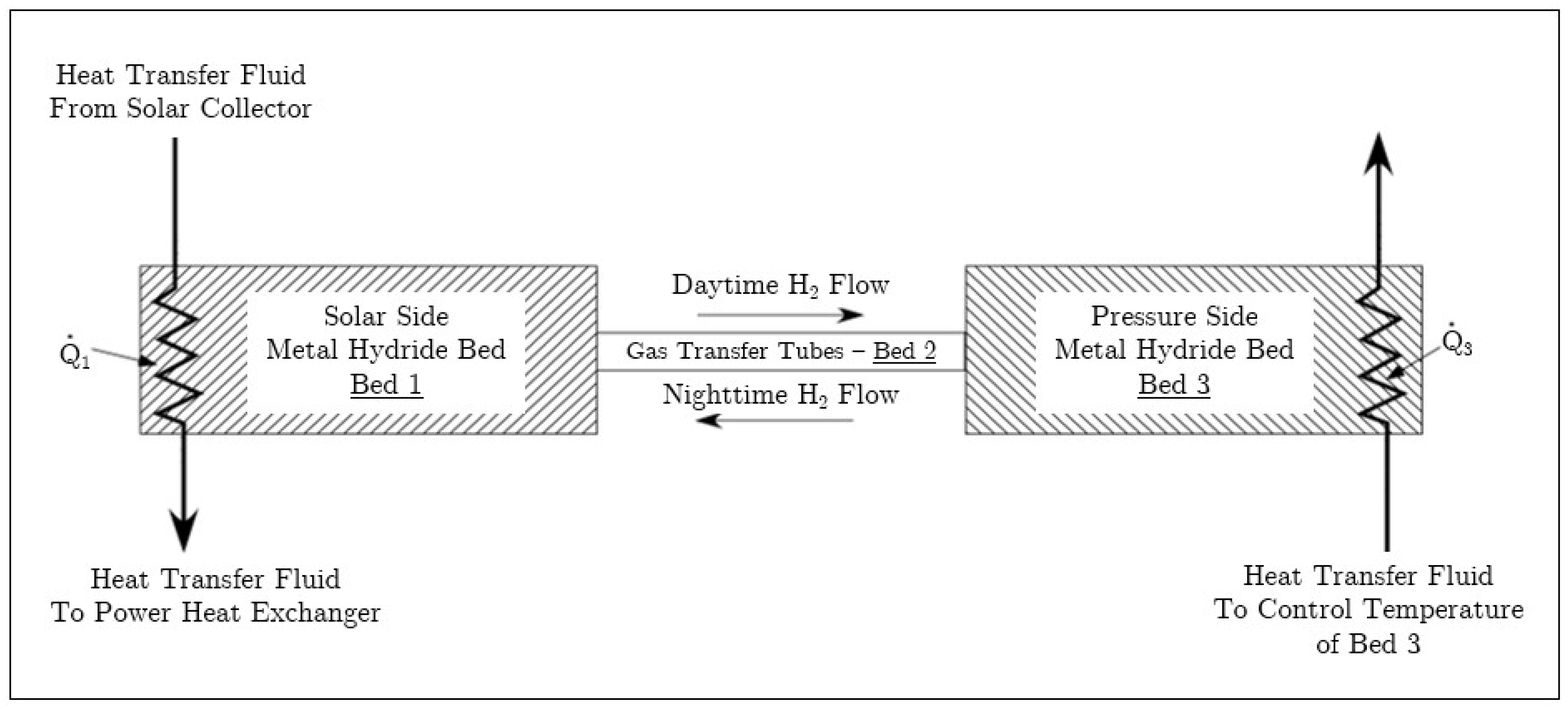
As illustrated in Figure 1, during periods of high solar irradiation the high-temperature bed (Bed 1 in Figure 1) releases hydrogen that flows to the low-temperature bed (Bed 3 in Figure 1). As the pressure increases, the low-temperature bed reacts to uptake hydrogen. During periods of low or no solar irradiation, the high-temperature bed cools and the pressure decreases. The reduction in pressure causes hydrogen to be released from the metal hydride in the low-temperature bed and the high-temperature bed begins to uptake hydrogen. The heat of reaction associated with hydrogen uptake in the high-temperature bed results in heat transfer to the working fluid. The heat is transferred at a temperature that is dictated by the chemical kinetics of the high-temperature metal hydride.

Figure 1.
Schematic of tandem bed for solar energy storage.
A comprehensive review and techno-economic analysis of the metal hydride materials, currently available to be employed in thermal energy storage units, can be found in References [7,8,9,10,11]. Three main classes of high-temperature hydrides, currently available, have been identified for possible use in thermal energy storage. The first class of materials is comprised of Mg-based compounds and operates at temperatures of approximately 300–450 °C, with reaction enthalpies on the order of 70–80 kJ/(mol H2) [7,12,13,14]. Mg-based hydrides were also demonstrated experimentally for small scale power plants, operating at temperatures on the order of 450 °C and demonstrating cycling stability [15,16]. The second class is comprised of Na-based hydrides, operating at temperatures on the order of 450–650 °C and at reaction enthalpies on the order of 75–100 kJ/(mol H2) [17,18,19]. The third class of materials is comprised primarily of Ca, Ti an Li based compounds, including destabilized hydrides. These materials can operate at temperatures higher than 700 °C, with reaction enthalpies generally higher than 90 kJ/(mol H2) [7,20,21,22,23,24,25].
This paper focuses on metal hydride based energy storage for concentrating solar power (CSP) collectors, which function by converting solar energy to heat. The heat is then transferred to a working fluid that drives a turbine to generate electrical power. The influence of the ‘thermal ratcheting’ on the overall system performance is described and quantified for a coupled metal hydride thermal energy storage plant, adopting a lumped parameter transient transport phenomena model. A comparison between a ‘non-balanced’ and a ‘thermally balanced’ coupled metal hydride system is also provided and discussed.
2. Methods and Analysis
The application of metal hydrides for energy storage requires a sufficient mass of hydride to store and supply the heat required for the power block. Further, the beds must be both synchronistic and sized appropriately so that hydrogen discharged by one bed can be stored by the other. It would defeat the purpose of the system if the discharged hydrogen exceeded the capacity of the receiving bed so that the released hydrogen must be stored by pressurization. Ensuring adequate bed sizing and compatibility of chemical kinetics requires the use of numerical models. For this purpose, the models are global for each bed and include mass and energy conservation. It has been observed from detailed models and experiments conducted for the DOE Hydrogen Storage Engineering Center of Excellence that pressure gradients in the hydride beds can be neglected, even during rapid charging processes [26]. Hence, in the global models for the energy storage system, it is assumed that the pressure is uniform throughout the system.
2.1. General Approach
A tandem bed scoping model is used to evaluate metal hydride combinations and bed configurations utilized for solar energy storage. This calculation employs the global mass and energy balances for the storage system. Chemical kinetics, which govern hydrogen uptake and discharge, are defined by a general equation containing parameters determined by fitting data for particular metal hydrides. Real gas properties are obtained from the NIST REFPROP [27] database.
2.2. Model Formulation
2.2.1. Geometry
A schematic of the tandem bed system is shown in Figure 1. In the figure, Beds 1 and 3 contain metal hydrides and represent the high and low-temperature beds, respectively. The gas transfer tubes between the high and low-temperature beds are designated as Bed 2 and are solely for transporting gas; these tubes do not contain metal hydride. [W] denotes the net heat transfer to Bed 1 and includes solar heat entering the bed as well as heat transfer out to the working fluid. Similarly, denotes the net heat transfer to Bed 3, which can include process waste heat used to enhance hydrogen discharge from Bed 3. Beds 1 through 3 are a closed system and operate without addition of hydrogen, pumps or other externally applied work.
2.2.2. Model Assumptions
The model employs the following assumptions:
- The process is uniform for each bed. That is, there is no spatial dependence for any properties or dependent variables.
- The pressure is approximately uniform throughout the entire control volume. Although a pressure gradient is required to drive gas flow between the beds, it is very small because the process is relatively slow. Therefore, for the purpose of the scoping model, the pressure is approximately uniform.
- The real-gas hydrogen equation of state and enthalpy are given by NIST-REFPROP [27]. However, for the range pressures and temperatures for the system, hydrogen behaves as an ideal gas.
- Heat transfer to Beds 1 and 3 occurs only via the heat exchangers and convection by hydrogen flow.
- Heat transfer to Bed 2 occurs only via convection due to hydrogen flow.
2.2.3. Hydrogen Mass Conservation
For , let [mol/m3] be the concentration of hydrogen in the gas phase of Bed i at time t [s], for , which is assumed to be a smooth real valued function. Let the starting time of the reaction be at . The global hydrogen mass conservation equation for the control volume consisting of all 3 beds, see Figure 1, is
where
Porosity of Bed i [unitless]
Volume of Bed i [m3]
Molar flowrate of incoming gas [mol/s]
Molar flowrate of outgoing gas [mol/s]
Source of hydrogen for Bed i [mol/s]. This quantity is negative for hydrogen uptake by the metal hydride.
There are several things to note. First, since control volume is closed. Furthermore, the porosity of Bed 2, the transfer tubes, is simply . Lastly, from here forward only consider for any variables which are not relevant to Bed 2, such as the source of hydrogen, .
Therefore,
The source terms are given by the metal hydride kinetics equations and the balanced chemical reaction equation for hydrogen and the metal hydride.
For Beds 1 and 3, which contain metal hydride, the mass conservation equation for hydrogen is
where
Molar flowrate of hydrogen out of Bed i [mol/s].
Consider , the number of moles of hydrogen in Bed i, as a continuous, real valued function of time. However, smoothness is not necessarily assumed, hence may not be continuous. Note that is not necessarily 0 since the control volume for Bed i is open.
For Bed 2, which represents the tubes connecting Beds 1 and 3, the hydrogen mass conservation equation is
Substitute for and from Equation (3) to get
For a real gas,
where
Compressibility factor at temperature, T, and pressure, P, [unitless]
Gas constant [J/(mol·K)].
2.2.4. Metal Hydride Mass Conservation
Postulate a chemical reaction equation for the metal hydride, having the form
where
Stoichiometric coefficient for species j, for [unitless].
For the chemical reaction given by Equation (8), the change in moles of each component are related by
where
Change in moles of species j due to the chemical reaction [mol].
= Change in concentration of hydrogen due to reaction [mol/m3]
Concentration of species j in Bed i [mol/m3].
2.2.5. Energy Conservation
The global energy conservation equation for Beds 1 and 3 is given by, for ,
where
= Molar enthalpy of hydrogen in Bed i [J/mol]
Molar enthalpy of hydrogen entering or leaving Bed i [J/mol]
Specific internal energy of species j in Bed i [J/kg]
Density of species j in Bed i [kg/m3]
The rate of heat transfer to Bed i [W].
Expand the derivatives
For a solid (namely the hydrided and un-hydrided metal) and is approximately independent of pressure so that,
where
Specific enthalpy of metal [J/kg]
Specific heat capacity of metal [J/(kg·K)].
For now, drop the notation of t dependence of these functions. Group the hydrided and un-hydrided metal together and write
where
Overall density of Bed i [J/kg]
Overall specific heat capacity of Bed i [J/(kg·K)].
Further, for the hydrating reaction,
where
Specific enthalpy of species j in Bed i [J/kg].
Note that the enthalpy of reaction, [J/mol H2], is given as
Note that on uptake of H2 by the metal hydride if the reaction is exothermic (which it is). Substituting the above relations into Equation (15) gives
2.2.6. Kinetics Expression
The source terms, and , derive from the reaction kinetics for the metal hydrides employed in Beds 1 and 3. Models for the kinetics are dependent on temperature and pressure and differ for the particular metal hydride. If the kinetics are sufficiently rapid, hydrogen uptake and discharge by the metal hydride can be approximated using an isotherm. The United Technologies Research Center has postulated an equation for metal hydride kinetics, applicable to single step reactions [28]. For ,
where
Arrhenius pre-multiplier for Bed i (a parameter fit from data) [s−1]
Parameter from fit to data, same for both Beds 1 and 3 [unitless]
Activation energy in Bed i [J/mol]
Concentration of metal hydride in Bed i when fully converted from metal form [mol/m3]
Equilibrium pressure [Pa] of the metal hydride-hydrogen system at temperature T
An equilibrium concentration factor [unitless].
The equilibrium pressure is given by the van’t Hoff equation
where
Enthalpy of reaction in Bed i [J/mol]
Entropy of reaction in Bed i [J/(mol·K)].
3. Results and Discussion
Hypothetical Pair of Metal Hydrides
As an illustrative example of the operation of the metal hydride solar energy storage system, consider a pair of metal hydrides that each have different reaction kinetics and chemical properties, but both have the mass action equation
The stoichiometric coefficients are thus
The parameters and properties for the metal hydrides in Beds 1 and 3 are listed in Table 1 (). The parameters are for a hypothetical pair of materials, with the stoichiometry of NaAlH4 and thermodynamic properties suitable for a high-temperature metal hydride (Bed 1) coupled a metal hydride with thermodynamic properties suitable for a low-temperature metal hydride (Bed 3). The properties of the metal hydrides in Beds 1 and 3 are listed in Table 1. The volumes of Beds 1, 2, and 3 are assumed equal to 20 m3, 0.025 m3, and 60 m3, respectively.

Table 1.
Parameters for Beds 1 and 3.
As a performance test, the model was applied to a very small CSP system for which the high-temperature bed receives 300 W of net thermal power during the day, which is the total thermal power less heat transfer to the working fluid for the electric power system and other losses. Net heat transfer to the high-temperature bed results in dissociation of hydrogen, which flows to the low-temperature bed.
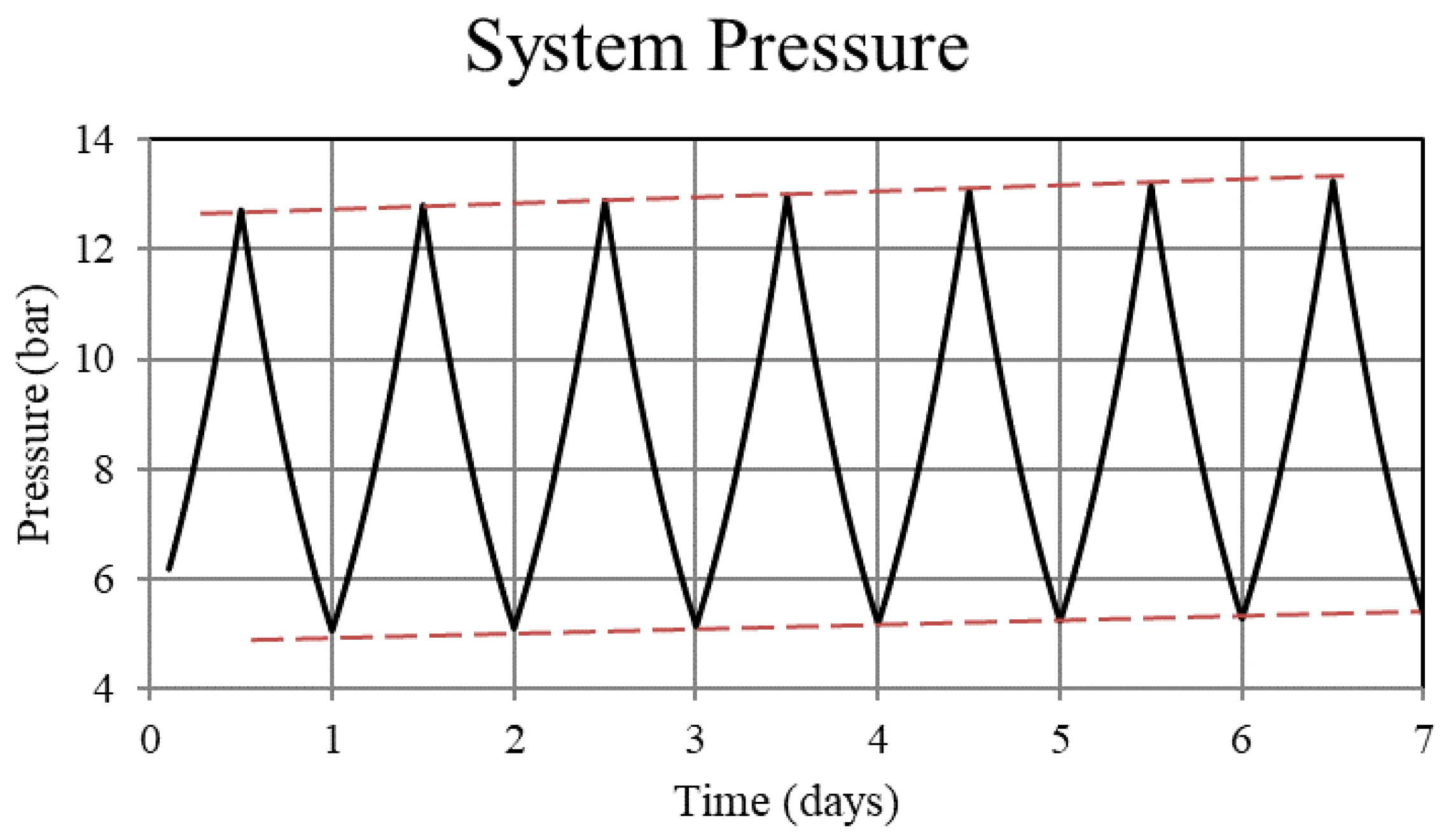
In the scoping calculations two cases were considered. The first case, referred to as ‘a non-thermally balanced system’, sees 300 W of solar heat transferred to the metal hydride in the high-temperature bed (Bed 1) during the day and 300 W extracted from the high-temperature bed during the night, i.e., W. The day and night portions of the complete 24 h cycle are each assumed to be 12 h long and the power is assumed to be constant over each part of the cycle. For this case there is no heat transfer, other than that by convection of hydrogen, to or from the low-temperature bed (Bed 3), i.e., W. The piping that connects the high and low-temperature beds is assumed to be adiabatic. The performance of the system for this case is shown in Figure 2, Figure 3, Figure 4, Figure 5 and Figure 6.
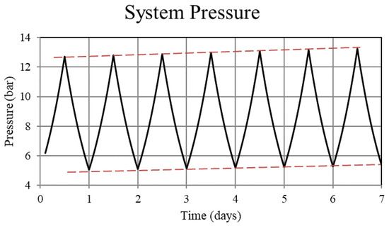
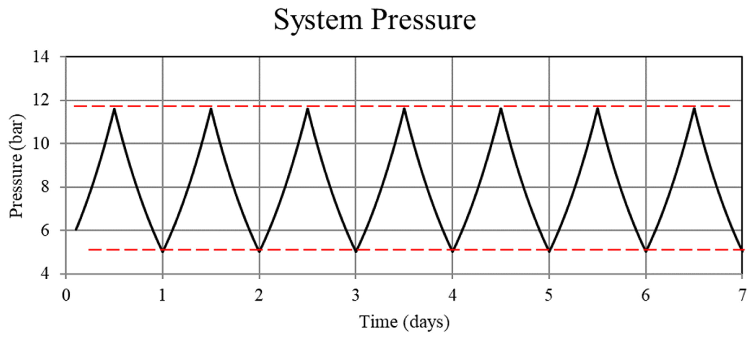
Figure 2.
System pressure for the non-thermally balanced system. Operation of the non-balanced system results in an upward trend in the system pressure.
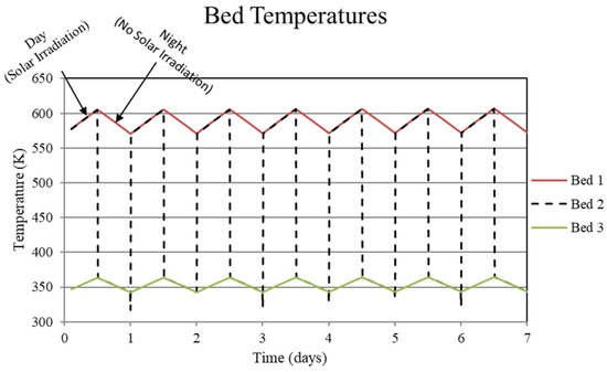
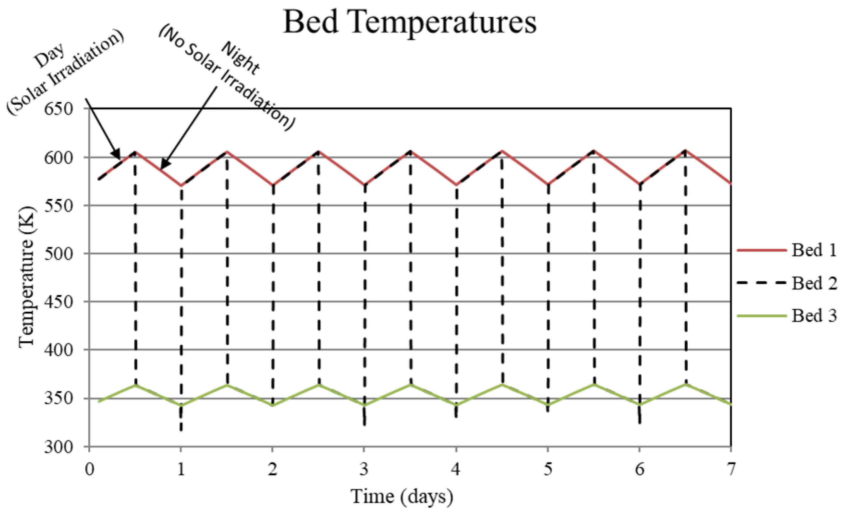
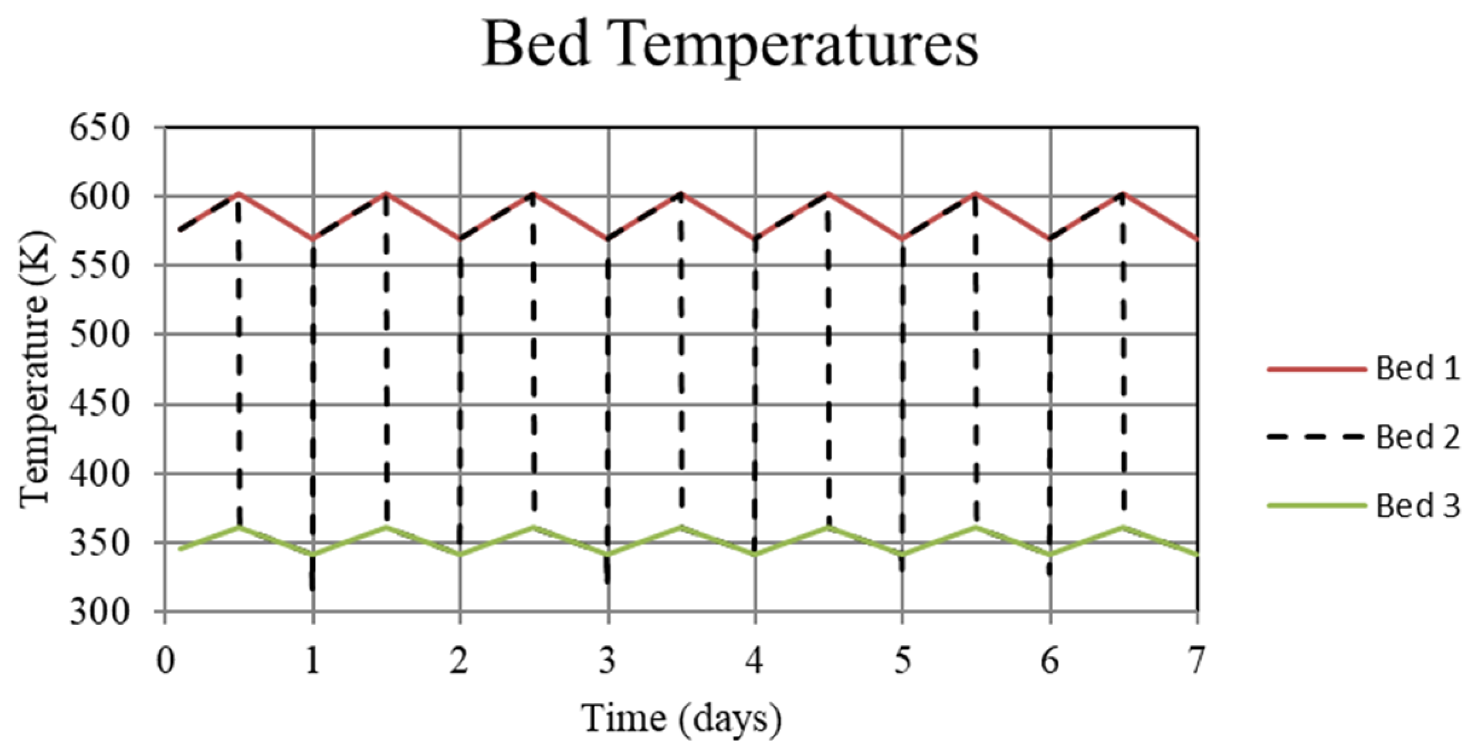
Figure 3.
System temperatures for the high-temperature metal hydride, Bed 1, the connecting pipeline, Bed 2, and the low-temperature metal hydride, Bed 3, for the non-thermally balanced system. This case results in a slight cycle to cycle increase in the high and low-temperature beds.
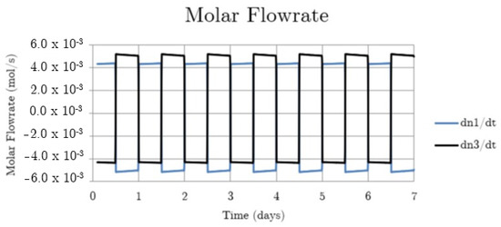
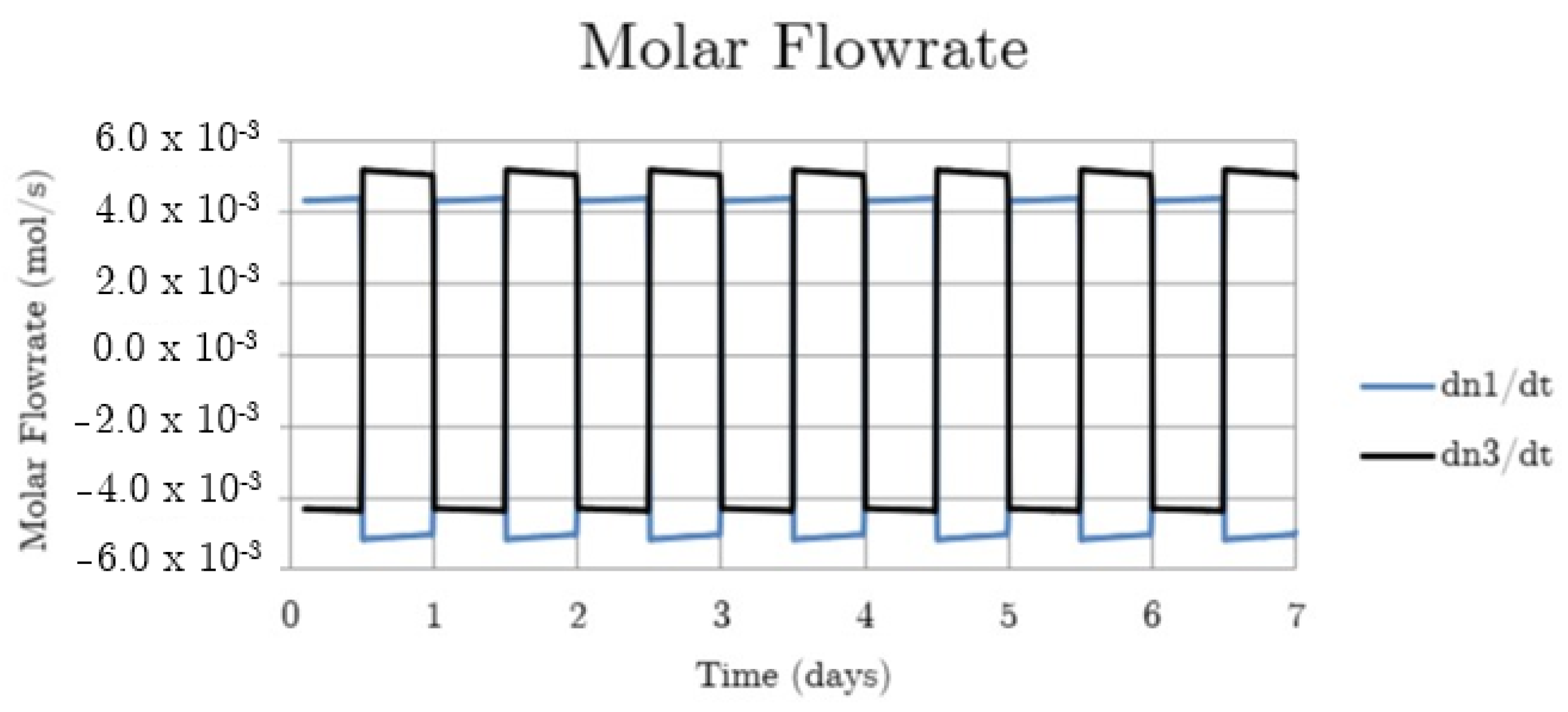
Figure 4.
System hydrogen flowrate for the non-thermally balanced system.
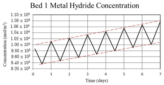
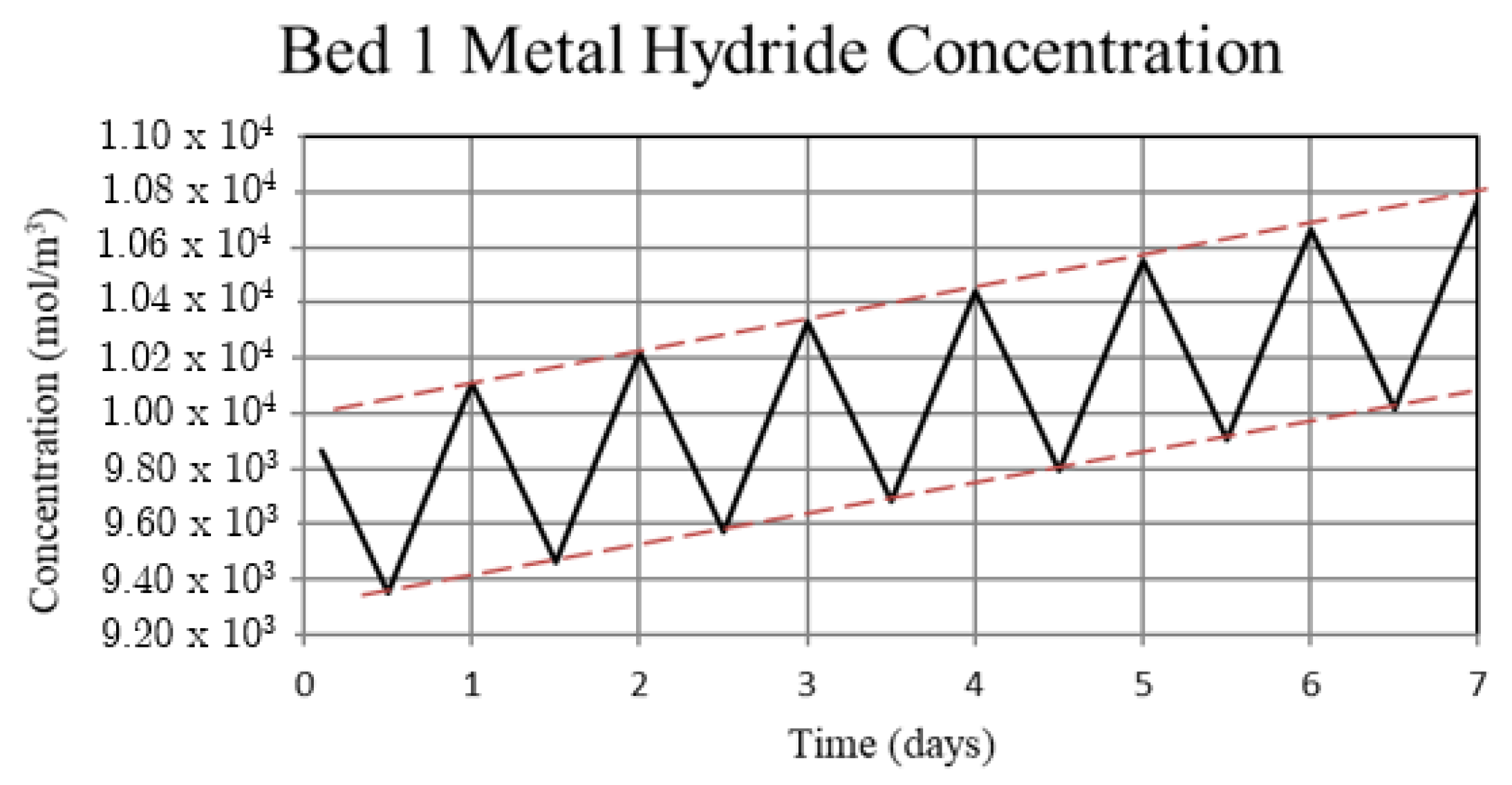
Figure 5.
Metal hydride concentration in the high-temperature metal hydride, Bed 1, for the non-thermally balanced system. The metal hydride concentration is a measure of the hydrogen uptake by the bed.

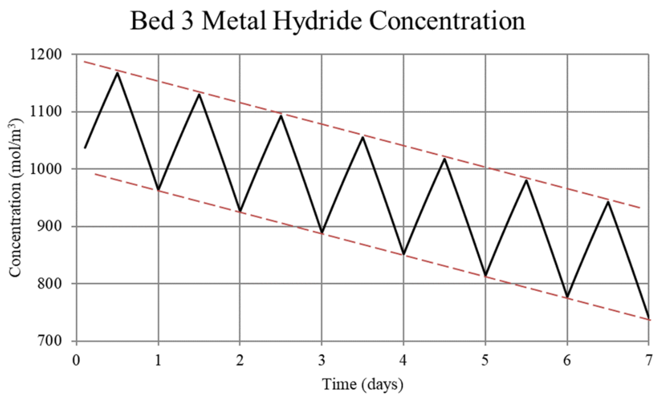
Figure 6.
Metal hydride concentration in the low-temperature metal hydride, Bed 3, for the non-thermally balanced system. The metal hydride concentration is a measure of the hydrogen uptake by the bed.
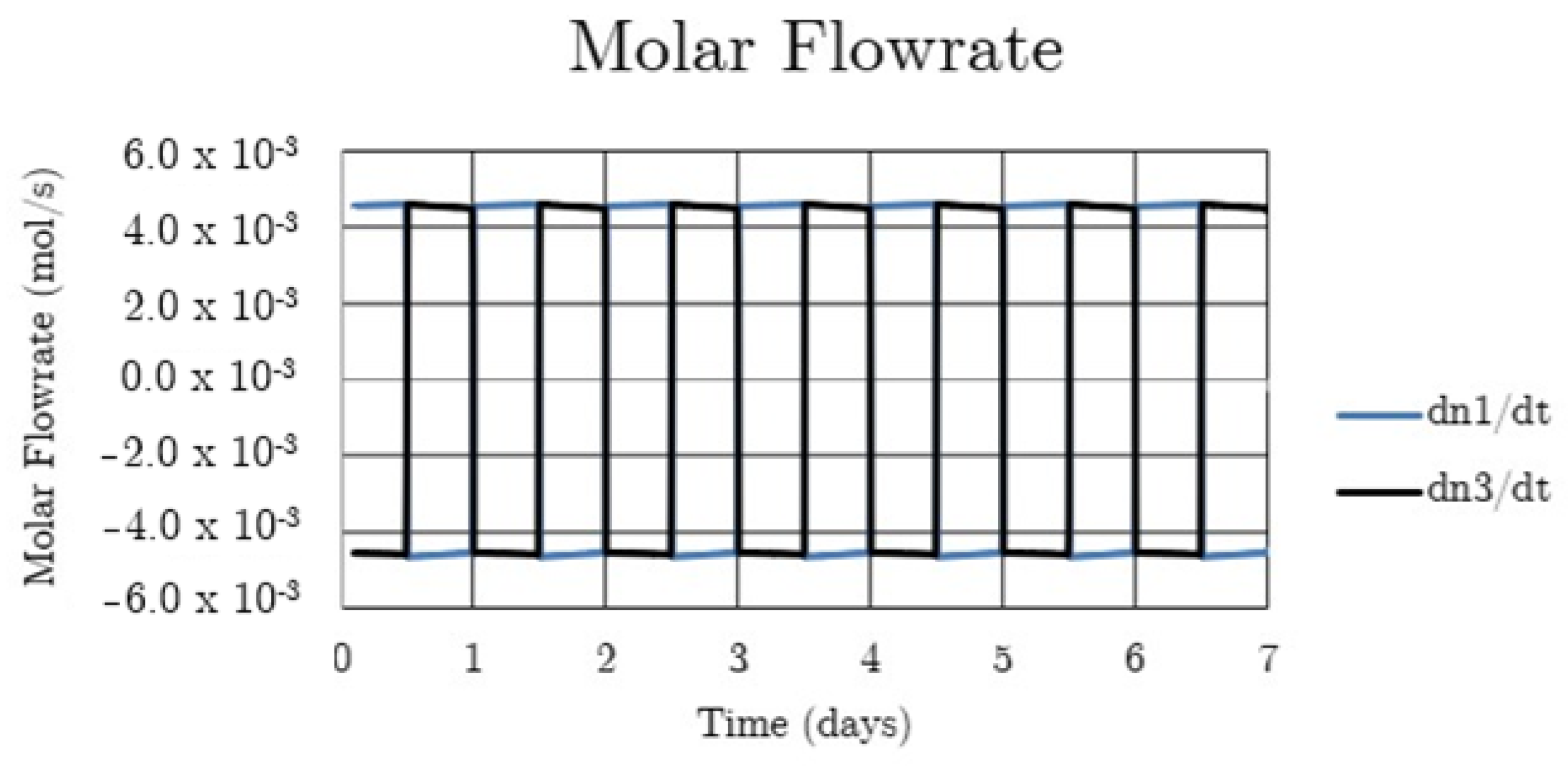
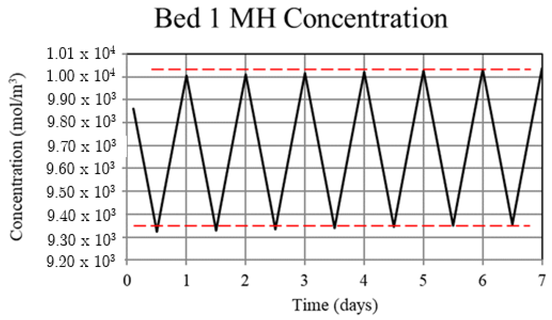
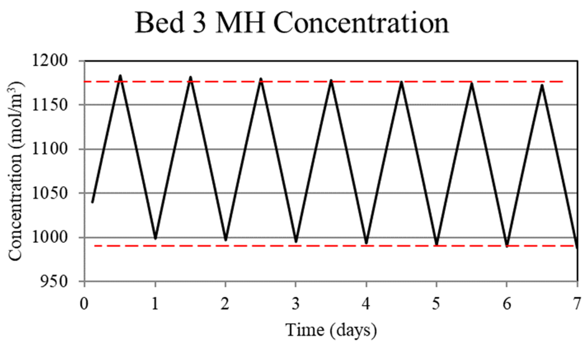
The second case, referred to as ‘a thermally balanced system’ sees the same cycle day/night cycle times. However, in this case, the net power supplied to the high-temperature bed is constant at 300 W during the day and a constant power of 270 W is extracted from the bed during the night. The low-temperature bed is cooled during the day, with a constant 30 W of heat removed, i.e., W. During the night there is no net heat transfer to the low-temperature bed, i.e., W. The performance of this case is shown in Figure 7, Figure 8, Figure 9, Figure 10 and Figure 11.
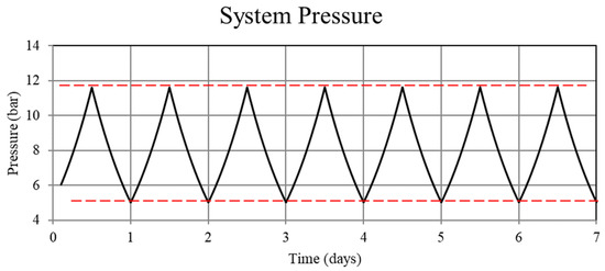
Figure 7.
System pressure for the thermally balanced system. Although difficult to see in this figure (the pressure appears to be periodic everywhere), the pressure becomes periodic after the first few cycles.
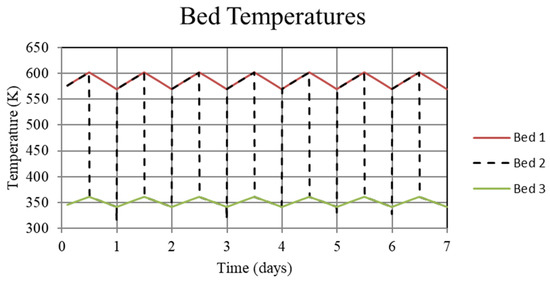
Figure 8.
System temperatures for the high-temperature metal hydride, Bed 1, the connecting pipeline, Bed 2, and the low-temperature metal hydride, Bed 3, for the thermally balanced system. For this case, temperatures in both Bed 1 and Bed 3 are periodic after the first few cycles.

Figure 9.
Hydrogen flowrates entering and exiting Beds 1 and 3 for the thermally balanced system. In this case the entering and exiting flowrates display reflective symmetry after the first few cycles.
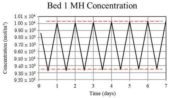
Figure 10.
Metal hydride concentration in the high-temperature metal hydride, Bed 1, for the thermally balanced system. The metal hydride concentration is a measure of the hydrogen uptake by the bed and becomes periodic after the first few cycles.
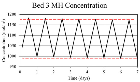
Figure 11.
Metal hydride concentration in the low-temperature metal hydride, Bed 3, for the thermally balanced system. The metal hydride concentration is a measure of the hydrogen uptake by the bed and, as for the high-temperature bed, shown in Figure 10, becomes periodic after the first few cycles.
For Case 1, in which the system is not thermally balanced, cyclic operation results in accumulation of hydrogen in the high-temperature bed and depletion of hydrogen in the low-temperature bed. In this paper, the accumulation/depletion process is referred to as “thermal ratcheting” and is shown as the cycle to cycle increase in the metal hydride concentration in the high-temperature bed accompanied by a decrease in the low-temperature bed, see Figure 5 and Figure 6. Eventually, when the high-temperature bed can no longer uptake hydrogen, discharge from the low-temperature bed continues until the system reaches temperature dependent equilibrium pressure of the low-temperature bed. This situation defeats the purpose of generating heat via reaction enthalpy in the high-temperature bed as the bed will no longer uptake hydrogen. After saturation, the only heat generation in the high-temperature bed will be due to pure pressurization, which is insufficient to supply the necessary power during the night.
The reason for the increase in hydrogen loading in the high-temperature bed (Bed 1) is due to the transfer of lower temperature gas from the low-temperature bed (Bed 3) to Bed 1 which, by virtue of the equilibrium pressure equation and the kinetics equation for the metal hydride, increases uptake in Bed 1. The converse occurs for Bed 3. In Bed 1, the reduction in internal energy due to cooler gas is offset by the cyclic increase in internal energy due to the molar enthalpy of reaction associated with the net cyclic increase in hydrogen taken up by Bed 1. The net increase in stored thermal energy results in small cycle to cycle increase in temperature for Bed 1, see Figure 3. In Bed 3, a net increase in internal energy occurs due to the transfer of higher temperature gas from Bed 1 in spite of the increase in cycle to cycle hydrogen discharge. This occurs because of the lower molar enthalpy of reaction for the metal hydride in Bed 3. As a result, the cycle to cycle temperature of the Bed 3 undergoes a slight increase, see Figure 3.
Understanding the mechanism for the thermal ratcheting effect leads to an immediate means for its mitigation, which is the basis for the thermally-balanced model of Case 2. Here, the 30 W of heat removal from the low-temperature bed, Bed 3, during the day reduces the bed temperature and thus increases the hydrogen uptake. The reduction in the heat removed from the high-temperature bed, Bed 1, during the night to 270 W as opposed to 300 W for the Case 1 model, serves to prevent the bed temperature from decreasing over the uptake part of the cycle as much as in Case 1. As a consequence, the increased Bed 1 temperature reduces the hydrogen uptake. Taken together, operation under these conditions results in cycle-wise stabilization of the hydrogen content of the high and low-temperature beds after a few cycles. This is shown in Figure 10 and Figure 11 where the hydrogen content of the beds is represented by the metal hydride concentration. From Figure 8, it can be seen that operating in this way maintains a periodic temperature cycle in both beds. Operation under the conditions of Case 2 result in a viable thermochemical system for solar energy storage.
4. Conclusions
A model was developed and applied to operation of solar energy storage systems that employ tandem metal hydride beds. The model demonstrated that the system is viable for a given pairing of metal hydrides, provided that the beds are properly sized and appropriate operating conditions are imposed. The model indicated that without operational control, the system underwent a thermal ratcheting process.
Specifically, thermal ratcheting can occur for a system that is not thermally balanced and will, after a number of day-night cycles, result in failure to recover thermal energy during the night. However, thermal ratcheting can be mitigated by thermally balancing the system, which consists of adding low-quality heat to the low-temperature bed during daytime operation and reducing the rate of heat transfer from the high-temperature bed during the night. By appropriately sizing the system, night-time power requirements can be met. The analysis indicated that thermally balanced systems stabilize after the first few day-night cycles and remain so for long-term operation.
Author Contributions
Conceptualization, B.J.H. and C.C.; methodology, B.J.H. and C.C.; software, B.J.H. and C.C.; validation, B.J.H., C.C. and S.N.G.; formal analysis, B.J.H., C.C. and S.N.G.; investigation, B.J.H., C.C. and S.N.G.; resources, B.J.H., C.C. and S.N.G.; writing—original draft preparation, B.J.H., C.C. and S.N.G.; writing—review and editing, B.J.H., C.C. and S.N.G.; visualization, B.J.H., C.C. and S.N.G.; supervision, B.J.H. and C.C.; project administration, B.J.H. and C.C.; funding acquisition, B.J.H. and C.C. All authors have read and agreed to the published version of the manuscript.
Funding
This material is based upon work supported by the Department of Energy, Office of Energy Efficiency and Renewable Energy (EERE), under Award Number DE-EE0007118.
Institutional Review Board Statement
This report was prepared as an account of work sponsored by an agency of the United States Government. Neither the United States Government nor any agency thereof, nor any of their employees, makes any warranty, express or implied, or assumes any legal liability or responsibility for the accuracy, completeness, or usefulness of any information, apparatus, product, or process disclosed, or represents that its use would not infringe privately owned rights. Reference herein to any specific commercial product, process, or service by trade name, trademark, manufacturer, or otherwise does not necessarily constitute or imply its endorsement, recommendation, or favoring by the United States Government or any agency thereof. The views and opinions of authors expressed herein do not necessarily state or reflect those of the United States Government or any agency thereof.
Informed Consent Statement
Not applicable.
Data Availability Statement
No new data were created or analyzed in this study. Data sharing is not applicable to this article.
Acknowledgments
The authors wish to acknowledge L. Irwin, M. Lausten, and A. Schultz, who were the U.S. Department of Energy managers, for their useful discussions and direction.
Conflicts of Interest
The authors declare no conflict of interest. The funders had no role in the design of the study; in the collection, analyses, or interpretation of data; in the writing of the manuscript, or in the decision to publish the results.
Abbreviations
The following abbreviations are used in this manuscript:
| CSP | Concentrating solar power |
| DOE | Department of Energy |
| M | Metal (uh-hydrided) |
| MH | Metal Hydride |
References
- Kuravi, S.; Trahan, J.; Goswami, D.Y.; Rahman, M.M.; Stefanakos, E.K. Thermal energy storage technologies and systems for concentrating solar power plants. Prog. Energy Combust. Sci. 2013, 39, 285–319. [Google Scholar] [CrossRef]
- Alva, G.; Lin, Y.; Fang, G. An overview of thermal energy storage systems. Energy 2018, 144, 341–378. [Google Scholar] [CrossRef]
- Sharma, A.; Tyagi, V.V.; Chen, C.R.; Buddhi, D. Review on thermal energy storage with phase change materials and applications. Renew. Sustain. Energy Rev. 2009, 13, 318–345. [Google Scholar] [CrossRef]
- Ho, C.; Christian, J.; Gill, D.; Moya, A.; Jeter, S.; Abdel-Khalik, S.; Sadowski, D.; Siegel, N.; Al-Ansary, H.; Amsbeck, L.; et al. Technology advancements for next generation falling particle receivers. Energy Procedia 2014, 49, 398–407. [Google Scholar] [CrossRef] [Green Version]
- Kolb, G.J.; Alpert, D.J.; Lopez, C.W. Insights from the operation of Solar One and their implications for future central receiver plants. Sol. Energy 1991, 47, 39–47. [Google Scholar] [CrossRef]
- Yonezu, I.; Nasako, K.; Honda, N.; Sakai, T. Development of thermal energy storage technology using metal hydrides. J. Less Common Met. 1983, 89, 351–358. [Google Scholar] [CrossRef]
- Corgnale, C.; Hardy, B.; Motyka, T.; Zidan, R.; Teprovich, J.; Peters, B. Screening analysis of metal hydride based thermal energy storage systems for concentrating solar power plants. Renew. Sustain. Energy Rev. 2014, 38, 821–833. [Google Scholar] [CrossRef]
- Manickam, K.; Mistry, P.; Walker, G.; Grant, D.; Buckley, C.E.; Humphries, T.D.; Paskevicius, M.; Jensen, T.; Albert, R.; Peinecke, K.; et al. Future perspectives of thermal energy storage with metal hydrides. Int. J. Hydrog. Energy 2019, 44, 7738–7745. [Google Scholar] [CrossRef]
- Corgnale, C.; Hardy, B.; Motyka, T.; Zidan, R. Metal hydride based thermal energy storage system requirements for high performance concentrating solar power plants. Int. J. Hydrog. Energy 2016, 41, 20217–20230. [Google Scholar] [CrossRef] [Green Version]
- Feng, P.; Liu, Y.; Ayub, I.; Wu, Z.; Yang, F.; Zhang, Z. Techno-economic analysis of screening metal hydride pairs for a 910 MWhth thermal energy storage system. Appl. Energy 2019, 242, 148–156. [Google Scholar] [CrossRef]
- Prasad, J.S.; Muthukumar, P.; Desai, F.; Basu, D.N.; Rahman, M.M. A critical review of high-temperature reversible thermochemical energy storage systems. Appl. Energy 2019, 254, 113733. [Google Scholar] [CrossRef]
- Yartys, V.A.; Lototskyy, M.V.; Akiba, E.; Albert, R.; Antonov, V.E.; Ares, J.R.; Zhu, M. Magnesium based materials for hydrogen based energy storage: Past, present and future. Int. J. Hydrog. Energy 2019, 44, 7809–7859. [Google Scholar] [CrossRef]
- d’Entremont, A.; Corgnale, C.; Sulic, M.; Hardy, B.; Zidan, R.; Motyka, T. Modeling of a thermal energy storage system based on coupled metal hydrides (magnesium iron–sodium alanate) for concentrating solar power plants. Int. J. Hydrog. Energy 2017, 42, 22518–22529. [Google Scholar] [CrossRef]
- Reiser, A.; Bogdanović, B.; Schlichte, K. The application of Mg-based metal-hydrides as heat energy storage systems. Int. J. Hydrog. Energy 2000, 25, 425–430. [Google Scholar] [CrossRef]
- Wierse, M.; Werner, R.; Groll, M. Magnesium hydride for thermal energy storage in a small-scale solar-thermal power station. J. Less Common Met. 1991, 172, 1111–1121. [Google Scholar] [CrossRef]
- Bogdanović, B.; Hartwig, T.H.; Spliethoff, B. The development, testing and optimization of energy storage materials based on the MgH2· Mg system. Int. J. Hydrog. Energy 1993, 18, 575–589. [Google Scholar] [CrossRef]
- d’Entremont, A.; Corgnale, C.; Hardy, B.; Zidan, R. Simulation of high temperature thermal energy storage system based on coupled metal hydrides for solar driven steam power plants. Int. J. Hydrog. Energy 2018, 43, 817–830. [Google Scholar] [CrossRef]
- Sheppard, D.A.; Corgnale, C.; Hardy, B.; Motyka, T.; Zidan, R.; Paskevicius, M.; Buckley, C.E. Hydriding characteristics of NaMgH 2 F with preliminary technical and cost evaluation of magnesium-based metal hydride materials for concentrating solar power thermal storage. RSC Adv. 2014, 4, 26552–26562. [Google Scholar] [CrossRef]
- Poupin, L.; Humphries, T.D.; Paskevicius, M.; Buckley, C.E. A thermal energy storage prototype using sodium magnesium hydride. Sustain. Energy Fuels 2019, 3, 985–995. [Google Scholar] [CrossRef]
- Javadian, P.; Sheppard, D.A.; Jensen, T.R.; Buckley, C.E. Destabilization of lithium hydride and the thermodynamic assessment of the Li–Al–H system for solar thermal energy storage. RSC Adv. 2016, 6, 94927–94933. [Google Scholar] [CrossRef]
- Friedlmeier, G.; Wierse, M.; Groll, M. Titanium hydride for high-temperature thermal energy storage in solar-thermal power stations. Z. Phys. Chem. 1994, 183, 175–183. [Google Scholar] [CrossRef]
- Ward, P.A.; Teprovich, J.A., Jr.; Liu, Y.; He, J.; Zidan, R. High temperature thermal energy storage in the CaAl2 system. J. Alloys Compd. 2018, 735, 2611–2615. [Google Scholar] [CrossRef]
- Corgnale, C. Techno-Economic Assessment of Destabilized Li Hydride Systems for High Temperature Thermal Energy Storage. Inorganics 2020, 8, 30. [Google Scholar] [CrossRef]
- Rönnebro, E.C.; Whyatt, G.; Powell, M.; Westman, M.; Zheng, F.R.; Fang, Z.Z. Metal hydrides for high-temperature power generation. Energies 2015, 8, 8406–8430. [Google Scholar] [CrossRef] [Green Version]
- Li, Y.; Li, P.; Qu, X. Investigation on LiBH4-CaH2 composite and its potential for thermal energy storage. Sci. Rep. 2017, 77, 41754. [Google Scholar] [CrossRef] [Green Version]
- Hardy, B.J.; Anton, D.L. Hierarchical methodology for modeling hydrogen storage systems. Part I: Scoping models. Int. J. Hydrog. Energy 2009, 34, 2269–2277. [Google Scholar] [CrossRef] [Green Version]
- Lemmon, E.; Huber, M.; McLinden, M. NIST Standard Reference Database 23: Reference Fluid Thermodynamic and Transport Properties-REFPROP; Version 9.1; National Standard Reference Data Series (NSRDS); National Institute of Standards and Technology: Gaithersburg, MD, USA, 2013. Available online: https://tsapps.nist.gov/publication/get$_$pdf.cfm?pub$_$id=912382 (accessed on 26 October 2021).
- Pasini, J.M.; Corgnale, C.; van Hassel, B.A.; Motyka, T.; Kumar, S.; Simmons, K.L. Metal hydride material requirements for automotive hydrogen storage systems. Int. J. Hydrog. Energy 2011, 38, 9755–9765. [Google Scholar] [CrossRef] [Green Version]
Publisher’s Note: MDPI stays neutral with regard to jurisdictional claims in published maps and institutional affiliations. |
© 2021 by the authors. Licensee MDPI, Basel, Switzerland. This article is an open access article distributed under the terms and conditions of the Creative Commons Attribution (CC BY) license (https://creativecommons.org/licenses/by/4.0/).