Review

PEMFC Poly-Generation Systems: Developments, Merits, and Challenges

1
School of Engineering, Faculty of Science and Engineering, University of Wolverhampton, Telford TF2 9NT, UK
2
School of Engineering and Applied Science, Aston University, Aston Triangle, Birmingham B4 7ET, UK
3
Department of Sustainable and Renewable Energy Engineering, University of Sharjah, Sharjah P.O. Box 27272, United Arab Emirates
4
Chemical Engineering Department, Minia University, Elminia 61519, Egypt
*
Author to whom correspondence should be addressed.
Sustainability 2021, 13(21), 11696; https://doi.org/10.3390/su132111696
Submission received: 31 August 2021 / Revised: 18 October 2021 / Accepted: 20 October 2021 / Published: 22 October 2021
(This article belongs to the Special Issue Hydrogen and Fuel Cell Technology)

Abstract

:
Significant research efforts are directed towards finding new ways to reduce the cost, increase efficiency, and decrease the environmental impact of power-generation systems. The poly-generation concept is a promising strategy that enables the development of a sustainable power system. Over the past few years, the Proton Exchange Membrane Fuel Cell-based Poly-Generation Systems (PEMFC-PGSs) have received accelerated developments due to the low-temperature operation, high efficiency, and low environmental impact. This paper provides a comprehensive review of the main PEMFC-PGSs, including Combined Heat and Power (CHP) co-generation systems, Combined Cooling and Power (CCP) co-generation systems, Combined Cooling, Heat, and Power (CCHP) tri-generation systems, and Combined Water and Power (CWP) co-generation systems. First, the main technologies used in PEMFC-PGSs, such as those related to hydrogen production, energy storage, and Waste Heat Recovery (WHR), etc., are detailed. Then, the research progresses on the economic, energy, and environmental performance of the different PEMFC-PGSs are presented. Also, the recent commercialization activities on these systems are highlighted focusing on the leading countries in this field. Furthermore, the remaining economic and technical obstacles of these systems along with the future research directions to mitigate them are discussed. The review reveals the potential of the PEMFC-PGS in securing a sustainable future of the power systems. However, many economic and technical issues, particularly those related to high cost and degradation rate, still need to be addressed before unlocking the full benefits of such systems.

1. Introduction

The demand for economic and environmental-friendly power systems continues to increase globally due to rapid population growth as well as the depletion of fossil fuel resources and their environmental pollution impact [1]. Increasing the efficiency of the power system, reducing its cost, and minimizing its harmful greenhouse gases (GHG) emissions are attracting noteworthy efforts from both industry and research communities. Utilizing renewable energy sources (RESs), such as solar and wind, and poly-generation technologies are among the solutions to secure a sustainable energy future. Due to the intermittent nature of the RESs, the renewable power systems are not independent and need to be coupled with energy-storage devices, such as batteries and fuel cells, to secure a continuous supply of power to the end-users [2]. Poly-generation is an emerging type of technology in which electrical power is generated onsite in combination with capturing and utilizing the by-product heat, i.e., waste heat, of the power system to produce other media, mainly useful heat, or cooling, allowing the simultaneous production of electricity, heat, and cooling from one source of fuel, i.e., input energy, as shown in Figure 1. The poly-generation system (PGS) can be classified into CHP system producing heat and power, CCP system producing cooling and power, CWP producing freshwater and power, and CCHP system producing cooling, heat, and power.
PGS has the potential to yield energy efficiency and environmental benefits leading to satisfying a number of social and energy policy aims [3]. Additionally, the poly-generation concept is central for the development of Distributed/District/Decentralized Energy Generation (DEG) [4]. Compared to Centralized Energy Generation (CEG), DEG provides several advantages, such as reduced transmission and distribution losses, reduced primary energy demands, improved system efficiency, improved energy security, less environmental impact and CO2 emissions, and lower operating costs [3,5,6]. The most promising application of the PGSs is in the buildings sector, including residential, commercial, and industrial buildings, because they can reduce the high energy demand of these activities for electricity, hot water, and space heating or cooling [5,7,8]. As an example of the high energy demands for building applications, the thermal and electrical energy demands of the domestic facilities in the UK form around 45% of the total energy consumption [9]. Therefore, PGSs can be considered as one of the technology-led strategies for the countries to achieve low-carbon goals. They are currently undergoing rapid developments and receiving increased market activities in the different regions of the world due to their promising prospects [3]. For example, the total number of installed CHP systems in the US is around 4654 with a total power of 80,695.2 MW (as of 31 December 2019) [10]. In 2018, the CHP systems provided 6.9% of all electricity generated in the UK [11]. The market of PGSs is mainly driven by the growing governmental focus towards protecting the environment and reducing the carbon footprints of the energy sector. For example, in June 2019, secondary legislation on ‘The Climate Change Act 2008’ was approved in the UK which committed the country to achieve a 100% reduction in carbon emissions relative to the 1990 baseline by 2050 [12]. In September 2020, the European Union (EU) raised their 2030 target of reducing GHG emissions to at least 55% compared to 1990 levels [13]. The EU is aiming to become a climate-neutral society with net-zero GHG emissions by 2050 [14]. In September 2020, China pledged to become carbon-neutral by 2060 [15]. The US has set a goal to achieve CO2-free electricity by 2035 and net-zero emissions economy-wide by no later than 2050 [16]. Many other countries have approved laws formally establishing net-zero carbon targets, including, Sweden (by 2045), New Zealand, France, and Denmark (by 2050) [17].
The main prime-mover technologies for PGSs are Stirling Engines (SE), micro Gas Turbine (mGT), Internal Combustion Engine (ICE), Steam Turbine (ST), Photovoltaic Cell (PVC), and the different Fuel Cell (FC) technologies, including PEMFC, Solid Oxide Fuel Cell (SOFC), Phosphoric Acid Fuel Cell (PACF), Molten Carbonate Fuel Cell (MCFC), and Alkaline Fuel Cell (AFC) [18]. The prime-mover technologies can be deployed individually or in combination, creating the so-called hybrid power systems. Among the different prime movers, the FC, if hydrogen (H2) is produced using a clean route, is the key option to maximise the environmental benefits of the PGS. Arandian et al. [19] compared the different CHP systems, including FC, mGT, and ICE ones, in terms of environmental impact and economic profits. It was shown that FC-CHP exhibits a favourable performance compared to other CHP technologies. Fuel cell-based poly-generation systems (FC-PGSs) are very promising in the move toward more environmental and lower-energy consumption buildings [20]. Such systems can reduce the primary energy consumption for covering the electrical and thermal demands of domestic users [21,22].
The different FC technologies were proposed for the CHP systems, including SOFC [23,24], PACF [25], MCFC [26], and AFC [27,28]. Similarly, many investigations on CCHP systems adopted PACF [29,30], MCFC [31], SOFC [32], and PEMFC [33] as prime mover.
Among the different FC technologies, PEMFC is the most attractive option for FC-PGSs due to their low-temperature operation, quick start-up (around 30 s), high electrical efficiency (around 55%), high energy density, fast response to dynamic loads, good heat output, and long operational life cycle (around 40,000–50,000 h) [1,5,34,35,36,37]. PEMFC has already been recognised as promising energy conversion and powering technology in portable devices [38], transportation [39,40,41,42], and energy storage systems [43]. Additionally, PEMFC is one of the technology solutions that can be used to back up the seasonally intermittent electricity supply from the RESs, ensuring secure supply to all consumers and increasing the share of RESs in the global energy market. Furthermore, PEMFC can be used as a reactor for selective hydrogenation of unsaturated organic compounds, such as nitrobenzene and phenol [44].
Due to the potential role of the PEMFC-PGSs in mitigating GHG emissions, reducing global warming, and enabling the transition into a clean-energy future, this paper aims to provide an overview of the different types of PEMFC-PGS as well as highlighting their advantages, limitations, prospects, and commercial developments. The paper is structured as follows; first, the principle technologies used in PEMFC-PGS are described and explained. Second, the studies focusing on evaluating the energy, economic, and environmental performance of the different types of PEMFC-PGS are reviewed. Third, the recent commercial activities on PEMFC-PGS are summarized. Finally, the merits and remaining challenges of these systems are discussed.

2. PEMFC-PGS Units and Technologies

The PEMFC-PGS is composed of several units, including the PEMFC stack which is responsible for generating the electrical power of the system, fuel processor which is responsible for converting the hydrocarbon fuel into hydrogen required for the operation of the PEMFC stack, waste-heat recovery unit to capture the heat generated from the PEMFC stack, energy storage units, and other electrical and electronic units, as shown in Figure 2. This section provides an overview of the main technologies used for the different units of PEMFC-PGS.

2.1. PEMFC

PEMFC is an electrochemical device converting the chemical energy of the reactants, i.e., hydrogen and oxygen, into electricity, heat, and water. The main parts of a single PEMFC are a Proton Exchange Membrane (PEM) sandwiched between two Catalyst Layers (CLs), two Gas Diffusion Layers (GDLs), and two bipolar plates containing flow channels to deliver the reactants into the electrochemical reaction sites. During the operation, the hydrogen steam is delivered into the anode flow channels where its molecules get oxidized, with the help of a catalyst, producing hydrogen protons, which permeate through the membrane into the cathode side, and electrons, which travel through an external circuit to the cathode side producing the electrical current of the cell. The oxygen is provided in the cathode flow channel where its molecules combine with the protons and electrons coming from the anode to form water. In addition to the electricity and water, heat is also generated within the PEMFC due to the exothermic electrochemical reactions, the condensation of water vapour, and the Ohmic resistance of the membrane [45]. The working principle of the PEMFC is presented in Figure 3. According to operating temperature (T), the PEMFC can be classified into low-temperature PEMFC (LTPEMFC) operating at a temperature of 60–80 °C, and high-temperature PEMFC (HTPEMFC) working at a higher temperature of approximately 120–200 °C [46]. Perfluorosulfonic acid (PFSA), such as Nafion, is typically used as a membrane in LTPEMFC while phosphoric acid (PA) doped poly-benzimidazole (PBI) is commonly employed as a membrane in HTPEMFC [46,47,48]. Nafion has outstanding proton conductivity and good mechanical and chemical stability at high relative humidity (RH) and low temperatures [49]. However, its performance drops significantly with decreasing RH or increasing T [49]. Therefore, many studies have suggested using fillers, such as CeO2-ACNTs, CeO2-TiC, and SO3H-UGNF, to modify the Nafion matrix and improve its electrochemical and mechanical properties [49,50,51]. In addition to Nafion, sulfonated polyether ether ketone (SPEEK) has attracted increased attention for PEMFC and DMFC membrane applications [52]. SPEEK membranes have many advantages compared to PFSA such as less water-dependency, lower cost, and lower methanol permeation [53]. However, the proton conductivity and material durability of SPEEK are less than those of PFSA as its non-sulfonated phenyl ether aromatic rings are susceptible to hydroxyl radicals attacks during PEMFC operation [54].
Due to elevated temperature in HTPEMFC, the stack is featured with improved water management, easier heat rejection, and less pressure drag within the reactants flow field [46,55]. Furthermore, HTPEMFC has higher tolerance towards fuel impurity, such as CO, than LTPEMFC and, therefore, its fuel processor is simpler than the one used for the LTPEMFC [46,56]. These benefits of HTPEMFC have resulted in deploying them for various commercial applications in transportation and stationary sectors [57,58,59]. However, the HTPEMFC exhibits greater activation over potential losses at both cathode and anode which reduces its efficiency compared to LTPEMFC [36]. Also, the various components of HTPEMFC, such as membrane, gas diffusion electrode, seals, gaskets, and bipolar plates, experience mechanical and chemical degradation at high temperatures which affect the performance of the HTPEMFC [60].
In addition to T, hydrogen pressure (PH2), air pressure (Pair), the relative humidity (RH), cathode and anode stoichiometric flow ratios ( ξ c , ξ a ), and the current density (i) are considered as key parameters of the PEMFC as they massively influence its performance [61,62]. Besides the aforementioned operating parameters, the reactants’ flow field configuration was found to have an influence on the performance of the fuel cell and it has been investigated in many studies [63].

2.2. Hydrogen Production Technologies

A hydrogen production facility is needed in the PEMFC-PGS to produce the hydrogen required for the operation of the prime mover, i.e., PEMFC. Such facility can be in the form of a fuel processing system extracting hydrogen from hydrocarbon fuels, such as natural gas (NG), or in the form of renewable energy-powered electrolyser for on-site generation of hydrogen from water. Producing hydrogen from hydrocarbons takes place in four main stages. In the first stage, the hydrocarbon is converted into hydrogen-rich syngas which can be achieved through either steam reforming (SR), autothermal reforming (ATR), or partial oxidation (PO), [64]. All reforming and partial oxidation processes take place in the presence of suitable catalysts, such as noble and transition metals, to improve the kinetics and decrease the temperature required for the reactions. Normally, a sulphur removal unit is used in the NG conversion system before starting the reforming or oxidation processes [65].
For SR, the fuel reacts with high-temperature steam producing hydrogen-rich syngas composed of hydrogen, carbon monoxide (CO), and small quantities of carbon dioxide. SR is an endothermic reaction requiring an external input of heat and it is favoured by high temperatures (normally above 800 °C) and high steam content (steam to carbon (S/C) ratio around 3.5) [64,65]. In the PO, the fuel partially oxidizes through reacting with small amounts of oxygen to generate mainly hydrogen, carbon monoxide, and heat [66]. ATR combines the SR and PO reactions into one single compact reactor; thereby the exothermic PO reaction generates the heat required for the SR process resulting in a net reaction enthalpy of zero [67,68]. ATR is attractive for small-scale production of hydrogen and provides many advantages over PO and SR. It yields a higher hydrogen production rate and efficiency compared to PO and it also shows higher energy efficiency, faster start-up and response times compared to SR [69]. Following the production of syngas, a water–gas shift (WGS) reaction is used in which CO reacts with the steam generating CO2 and more hydrogen. WGS is an exothermic reaction that typically takes place over two stages, including high-temperature shift at around 400 °C and low-temperature shift at around 200 °C, separated by a cooling step. WGS reduces the CO levels to less than 1 vol% and also enhances the hydrogen concentration within the mixture [65,70,71]. After the WGS process, a Preferential Oxidation (PrOx) reactor can be used to burn the remaining unconverted CO reducing the CO content in the fuel stream to less than 10 ppm [65]. The final stage of converting the hydrocarbon into hydrogen is a purification process, called Pressure-Swing Adsorption (PSA), which involves removing the carbon dioxide and other impurities, using beds of solid adsorbent, from the gas stream yielding pure hydrogen [72]. If a Carbon Capture and Storage (CCS) technology was used to capture and store the generated CO2, then the produced hydrogen is identified as blue hydrogen. If no CCS technology was utilized, the produced hydrogen is called grey or black hydrogen. The main stages of producing hydrogen from hydrocarbon feed are summarized in Figure 4.
The conventional hydrocarbons fuel processor is characterised by significant exergy losses due to the need for five reactors (one for syngas production, two for WGS, one for PrOx, and one for PSA) [65]. Membrane Reactor (MR) technology, which uses a hydrogen-selective membrane, such as palladium-silver (Pd-Ag) membrane, to simultaneously convert the hydrocarbon into syngas and separate high purity hydrogen, is beneficial to overcome the disadvantages of the conventional fuel processor. MR uses one reactor for the fuel conversion process which significantly increases the system efficiency [65]. Also, MR generates a fuel stream with extremely low impurities, i.e., CO, resulting in less degradation rates of the PEMFC and a longer lifetime of the PEMFC-PGS system.
In addition to hydrocarbons, hydrogen can be produced from other feedstock, such as water and biomass. In particular, producing hydrogen from water through electrolysis technology, such as Proton Exchange Membrane Electrolyser (PEMEL), Alkaline Electrolyser (AEL), and Solid Oxide Electrolyser (SOEL), is receiving a lot of interest due to its role in energy-storage applications and future renewable-energy systems [73]. The electrolysis process utilizes electrical power to split water into hydrogen and oxygen, as seen in Equation (1).
H 2 O Electricity   1 2 O 2 + H 2
If a Renewable Energy Source (RES), such as solar, wind, and geothermal, is used to generate the electrical power required for the electrolyser, the resulted hydrogen is called green hydrogen.
Biomass, such as agricultural residues and wastes of industries and households, is another rich source of hydrogen [74]. Producing hydrogen from biomass can be achieved through thermochemical and biochemical processes. Thermochemical processes, such as pyrolysis and gasification, are energy-demanding processes with higher efficiency and lower cost compared to biochemical [75,76]. The biochemical process, such as dark fermentation, utilizes micro-organisms to convert the organic materials, within the biomass, into hydrogen and other compounds [77].
Within the context of PEMFC-PGS, SR is the most commonly used technique to produce H2.

2.3. PEMFC Waste-Heat Recovery (PEMFC-WHR) System

In addition to the electrical power, PEMFC generates significant amounts of heat, as part of the energy conversion process, which is normally dissipated using a heat-management system, i.e., cooling circuit. Recently, various WHR techniques were proposed to capture the generated heat and enhance the energy-conversion efficiency of the PEMFC. The waste heat of the PEMFC can be considered as low-grade heat for both LTPEMF, operating at a temperature level of 60–80 °C, and HTPEMF, operating at a temperature level of 120–200 °C [45,46,78]. The PEMFC-WHR can be in the form of heat-to-heat through employing heat exchangers to recycle the heat into useful utilization, such as preheating the reactants or driving sorption chillers, or heat-to-power converting the heat into additional electricity using various thermodynamic cycles, such as an Organic Rankine Cycle (ORC), or direct heat-to-power technology, such as a Thermoelectricity Generator (TEG) [79,80,81]. A comprehensive overview of all PEMFC-WHR pathways was introduced in [45,82]. Within the context of PEMFC-PGS, the main aim of the WHR system is to convert the wasted heat of PEMFC into useful heating or cooling within the system. Heat-exchanger, absorption chiller, and chemical heat pump are the main technologies used for these purposes.

2.3.1. Heat Exchanger

The PEMFC-PGS utilizes many heat-exchangers that enable absorbing the heat from one part and transferring it into another part within the power station. Such heat-exchangers allow for the thermal integration between the hot and cold streams within the system, reducing the need for an external heat source and increasing the system efficiency.
For example, multiple heat-exchangers are normally used between the different reactors of the fuel processor to cool down the syngas before entering the PEMFC to avoid damage, degradation, and reduced performance of the stack [1]. An air stream is normally used as a coolant within these heat-exchangers and then the air is directed to be used within the combustor. Liquid–liquid, mostly water–water, heat-exchangers are also used to provide the heating load in the simple PEMFC-CHP through capturing the waste heat from the PEMFC and then transferring it into the system responsible for space heating or producing domestic hot water.

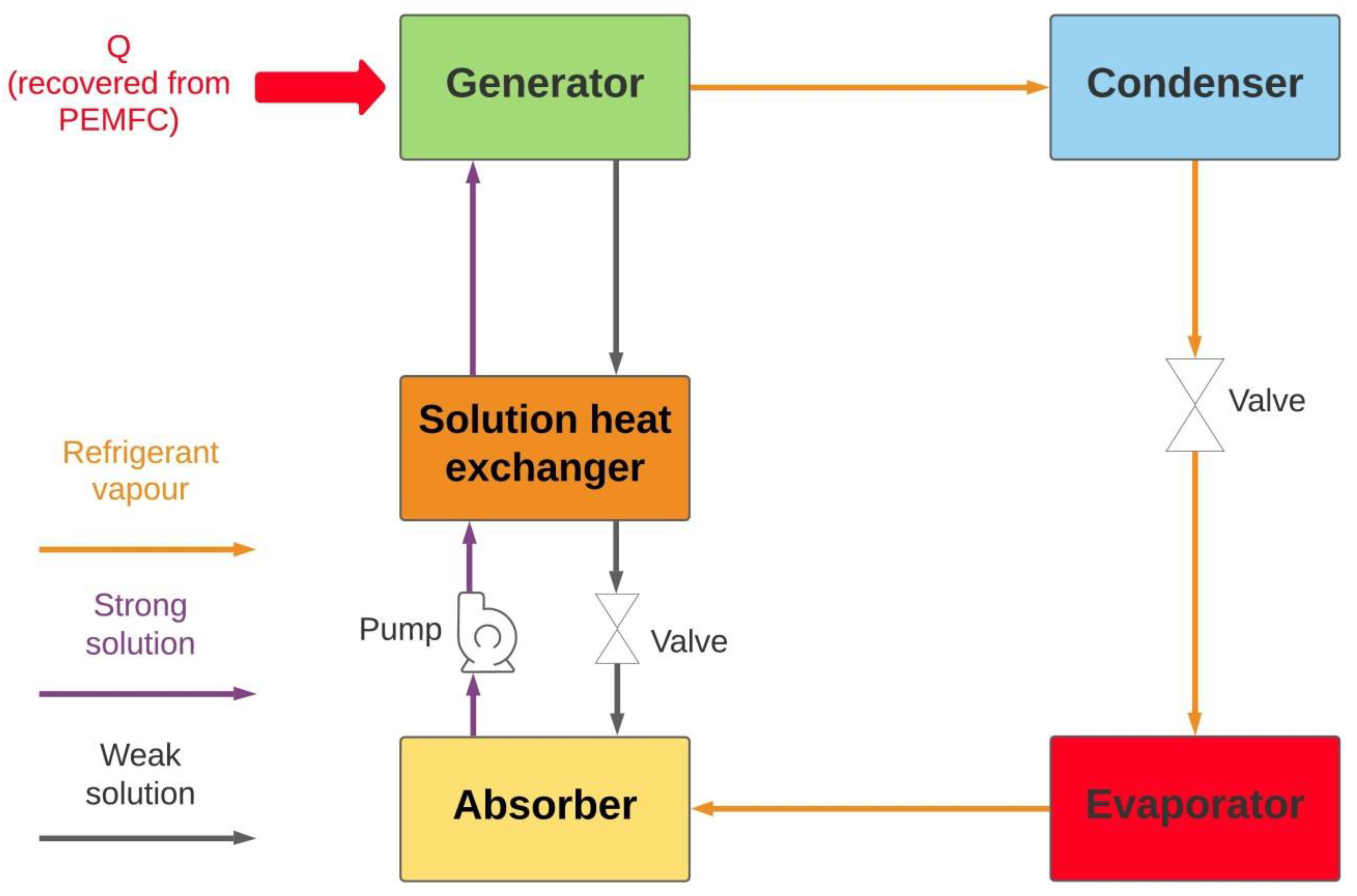
2.3.2. Absorption Chiller

Absorption Chiller (AC) is one of the thermally-driven sorption refrigeration technologies normally used in CCP and CCHP systems to produce cooling via the waste heat of the prime mover. AC is an environment-friendly cooling technology with less electrical consumption, noise, vibration, and negative environmental impact compared to conventional vapour-compression chillers. AC can be powered by a low-temperature heat source (80–200 °C) making them an ideal technology to be used for low-grade WHR, such as that in PEMFC [83,84,85]. Lithium bromide–water (LiBr–H2O) and water–ammonia (H2O–NH3) mixtures are commonly utilized as operation solutions, i.e., absorbent–refrigerant pairs, in AC chillers. The absorption–refrigeration system consists of absorber, generator, evaporator, and condenser, as shown in Figure 5. In the absorber, the refrigerant vapour, from the evaporator, gets absorbed by the weak solution forming the strong solution. The formed strong solution passes through the solution heat-exchanger where its temperature gets raised before entering the generator. In the generator, the PEMFC waste heat is used as a heat source to boil the strong solution separating the weak solution from the absorbed vapour. The weak solution flows back to the absorber while the vapour goes through the rest of the refrigeration cycle exchanging heat in the condenser and evaporator and producing the cooling effects. AC can be classified into single-effect or double-effect, depending on the number of generators and solution heat-exchangers. The double-effect chiller normally generates a higher Coefficient of Performance (COP) compared to a single-effect one. For example, the COP of the double-effect H2O-NH3 chiller is around 1.2 while it became 0.5–0.7 in a single-effect chiller [34].

2.3.3. Chemical Heat Pump

The chemical heat pump is another technology that can be used for low-grade waste-heat recovery through a reversible endothermic/exothermic reaction between chemicals without generating new substances or consuming the reaction’s substances [85]. Similar to the sorption refrigeration technologies, a chemical heat pump consists of a condenser, an evaporator and reactors where the chemical reaction takes place [86]. The chemical heat pump can be classified into either a liquid–gas absorption system or a solid–gas adsorption one. In fact, the absorption chiller is a gas–liquid absorption chemical heat pump. Different working pairs can be used for the absorption/adsorption chemical heat pumps such as chloride salts–ammonia, zeolite–water, and carbon–ammonia for adsorption systems; and magnesium oxide–water, and acetone/hydrogen/2-propanol for absorption systems [86].
Among the different chemical heat pump systems, the one employing the acetone/hydrogen/2-propanol has been proposed for PEMFC-WHR since the endothermic reaction takes place at 80–90 °C. This heat pump is a liquid–gas absorption with two reactors, one for the endothermic dehydrogenation reaction of the isopropanol and the second reactor for the exothermic hydrogenation reaction of acetone [87,88].

2.4. Energy Storage

Thermal and electrical energy storage facilities are essential parts of the PEMFC-PGS and other renewable-energy systems. They increase the flexibility and overall efficiency of the system by removing the mismatch between supply and demand and enhance the system’s ability to meet the high demand on thermal/electrical energy during the peak time [89,90]. Energy storage is critical to improve energy utilisation and reduce the economic losses within the poly-generation system [91].
Thermal Energy Storage (TES) can be either Sensible Heat Storage (SHS) or Latent Heat Storage (LHS). LHS employs phase change material (PCM), such as paraffin wax, molten salt, and water–ice, as a storage medium to store/release thermal energy (heat) as a result of a phase transition occurring at a constant temperature within such materials [92]. On the other side, SHS is achieved by changing the temperature, i.e., heating or cooling, of the storage material that can be either solid or liquid such as ceramic, water, or oil [93]. In SHS, the storage medium does not experience any change in its phase during charging or discharging. The well-insulated hot-water tank (HWT) is the most commonly used SHS facility in residential and industrial applications [94]. Most studies on PEMFC-PGS reviewed in this paper have considered hot-water tanks as TES systems.
Electrical Energy Storage (EES) technologies enable storing the electricity when produced in excess, during off-peak hours, for use during peak demand periods [95]. EES provides several advantages for the power system, such as meeting high demands on electricity, managing power generation, regulating supply and demand, enhancing power trustworthiness, minimizing the need for power import, and reducing the grid dependence of the system [96,97]. EES can be mechanical, such as flywheels and compressed air energy storage, electrochemical, such as batteries and flow batteries, and electromagnetic, such as capacitors and supercapacitors [98]. The various battery technologies are ideally suited for EES. Lithium-Ion Battery (LIB) with its high energy density is the most widespread battery technology as EES system, particularly for electric vehicles (EVs). However, LIB exhibits some fire and explosive safety risks due to the flammability of the electrolyte and the high activity of the electrodes [99,100]. The flow battery technologies, such as Redox Flow Battery (RFB), are preferred for stationary large-scale EES applications because their feeds, i.e., the two electrolytes, can store large quantities of energy and they also have independent power and capacity [101,102,103]. RFBs have lower cost, higher safety, and lower power density compared to LIBs. The solid-state battery, which uses a solid electrolyte, is another promising candidate for next-generation EES systems. Compared to other batteries, the solid-state battery may offer many gains such as better safety, higher energy and power densities, longer life, and a wider range of operation temperature [104,105,106].
For PEMFC-PGS, LIB is adopted in many investigations as EES system [107].

2.5. Other Subsystems

In addition to the aforementioned technologies, PEMFC-PGS contain some other subsystems including the following:
  • Electrical and electronic subsystem: the PEMFC stack generates low-voltage DC which is not suitable for domestic applications. Therefore, electronic conversion devices are normally used to control, adjust, and transform the electrical output of the PEMFC. For example, an inverter is normally used in the PEMFC-PGS to convert the low-voltage DC of the PEMFC to AC compatible with domestic electrical equipment. Also, for integrating the PEMFC-PGS with the national electricity grid, additional pieces of equipment are required to provide frequency synchronisation, control, and other power conditioning to enhance the exportability of the generated power as well as satisfying the quality that is required by the national grid;
  • Balance of Plant (BoP) components such as pumps, compressors, humidifiers, valves, pipework, sensors, etc.;
  • Auxiliary devices, such as a secondary boiler, providing additional thermal power when the heating generated by the PEMFC-PGS is not sufficient; and
  • User-friendly monitoring and control systems, such as smart-meter, LCD touch-screen, and remote control, allowing the customer to interact with the system easily and efficiently.

3. Performance of PEMFC-PGS

Many indicators can be used to assess the performance of the PEMFC-PGSs. The most common energy, exergy, and economic performance metrics that were presented in the literature are the gross electrical efficiency ( η el ( gross ) ) , net electrical efficiency ( η el ( net ) ) , the thermal efficiency ( η th ) , the cooling efficiency ( η c ) the system overall energy efficiency ( η CHP ,   η CCHP ) , the electrical exergy efficiency ( ψ el ) , the thermal exergy efficiency ( ψ th ) , the cooling exergy efficiency ( ψ c ) , the system overall exergy efficiency ( ψ CHP ,   ψ CCHP ) , the primary energy saving (PES) index, the levelized cost (LCOE), and the mean annual cost ( Co med ). The full definitions and equations of these metrics are summarized in Table 1.

3.1. CHP

3.1.1. PEMFC-CHP

The energy performance of PEMFC-CHP system was analysed in many studies. Gigliucci et al. [8] assessed the responses of PEMFC-CHP system that converts NG into electricity and heat for small residential applications in Italy. The system is made up of five main sections, including the fuel processor, PEMFC stack, the power conditioning system converting the DC into AC, liquid-to-liquid heat-exchanger as WHR system, and set of batteries responsible for allowing peak power and system load tracking. The measured electric and thermal efficiencies of the system at nominal conditions were 18% and 30%, respectively. The system performance under different operating conditions was assessed experimentally and mathematically. The obtained results proved that the system behaved as expected and the model provided satisfactory prediction for the system performance. Radulescu et al. [115] investigated experimentally the performance of PEMFC-CHP co-generation system fed by NG. Despite that the fuel cell performance was satisfactory, the co-generation system exhibited poor electrical and thermal performance. The system yielded global mean electrical and thermal efficiencies of 9.2% and 29%, respectively. The low electrical efficiency of the system was due to the electrical losses, caused by the complex electric architecture of the system, and the fuel reforming process which required significant energy input. Briguglio et al. [116] conducted an experimental analysis to evaluate the thermal and electrical performance of a 5 kW PEMFC-CHP system for residential applications. The system showed satisfactory performance with an overall efficiency of 80%. It was reported that reducing the convective heat losses of the PEMFC stack, through good insulation, can improve the co-generation efficiency. Barelli et al. [117] analysed the performance of PEMFC-based residential CHP system in terms of efficiency, fuel consumption, hot-water production, and response time using a Matlab® Simulink dynamic model. The considered system is composed of PEMFC, fuel processor, heat-exchangers, humidifier, and auxiliary hot-water boiler. The hydrogen required for PEMFC was obtained from methane using a fuel processor. The influence of the air relative humidity in the PEMFC on the system’s overall efficiency was explored. It was found that a higher humidity rate improves the PEMFC efficiency resulting in reduced consumption of methane. However, the best operating conditions of the CHP plant were obtained for a relative humidity of 50%. Xie and Wang [118] reported on the performance of a PEMFC-CHP prototype consisting of a natural gas steam reforming (NG-SR) unit, CO cleaning unit, PEMFC stack, WHR unit, and auxiliary unit. It was shown that the system can produce 200 W electrical power and 530 W thermal power with electrical and thermal efficiencies of 15.4% and 40.9%, respectively. Minutillo and Perna [119] conducted energy analysis, using a numerical model, for a residential PEMFC-CHP system composed of two PEMFC stacks, a NG-SR unit, a WHR unit, batteries, DC-AC converters, and auxiliary components such as compressors and pumps. It was pointed out that the CHP system provides significant energy savings compared to the separate generation of heat and electricity from conventional gas-fired boilers and centralized power plants. The CHP system can generate 2.5 kW thermal power and 2.2 kW electrical power with electrical and CHP efficiencies of 40% and 88%, respectively. Chang et al. [107] conducted a performance analysis, using Mathlab, on a 2 kW residential PEMFC-CHP with a LIB. It was found that using batteries can increase the average total efficiency of the system by 11.02% and reduce the daily hydrogen consumption by 14.47%. The average total efficiency of the system with a battery is 81.24%. Gandiglio et al. [120] explored the potential of PEMFC-CHP system for residential space heating via a floor heating system. It was found that the global efficiency of PEMFC-CHP coupled with floor heating is 80% and it is greater than the traditional system with radiators network where the global efficiency of such a system is about 43%. The reason for the better performance in the case of a floor heating system is that this system operates at a temperature of 35–45 °C which is less than the system based on wall-mounted radiators (normally operate at 60–80 °C) and, therefore, the floor heating is better suited for the low-grade waste-heat recovery of PEMFC.
Despite the high efficiency of the PEMFC, the PEMFC-CHP systems with conventional fuel processors, such as SR and ATR, exhibited somewhat low efficiency due to the multiple steps required to process the fuel and the associated energy losses. Therefore, many studies have investigated alternative fuel processors, such as MR [121,122], for PEMFC-CHP applications. Marcoberardino and Manzolini [123] assessed the techno-economic performance of a 5 kW micro CHP system using PEMFC along with MR to produce hydrogen. Two reactor configurations, including sweep gas and vacuum pump, were explored to reduce the surface area of the membrane. The system with sweep gas configuration showed a net electric efficiency of 41.21% which is greater than that for vacuum pump configuration. A similar investigation has been conducted by Foresti and Manzolini [124], who also evaluated the performance of PEMFC-CHP co-generation system using auto-thermal fluidized-bed MR for converting bio-ethanol to hydrogen. It was found that the net electric efficiency of the system is higher than 40% in the sweep-gas layout while it is less than 39% in the vacuum pump layout. However, the sweep-gas system requires a greater membrane area compared to the area of membrane needed for vacuum pump configuration. Foresti et al. [125] have expanded the previous work by investigating the impact of impurities (CO, N2, CO2, and CH4) in the feeding stream on the performance of PEMFC-CHP system using MR for hydrogen production. It was found that the influence of impurities depends on the operation mode of the anode in the PEMFC stack. The study investigated two operation modes of the anode including dead-end mode, which doesn’t require hydrogen recirculation, and the flow-through mode. In the dead-end anode, small amounts of impurities (around 0.5%) in the feeding stream can cause fast voltage drop and, therefore, purges are frequently needed to remove them and recover the voltage. For the flow-through operation, the cell voltage of the PEMFC was insensitive to the impurities.
The use PEMFC-CHP system was not limited to the domestic buildings but they were also proposed for other applications. For example, Guizzi and Manno [126] assessed the economic and energy performance of a PEMFC-CHP system used to cover the energy needs of an information and communication technology (ICT) centre. The co-generation system consists of a NG reforming unit to produce hydrogen, PEMFC to produce electrical power, and a heat-exchanger as a WHR system recovering heat from both the steam reformer and the PEMFC to cover the thermal energy requirements of an office building close to ICT. The electrical power generated by the PEMFC is used to cover the electrical loads of the ICT centre including those required for uninterruptible power supply (UPS), the transformer and the lighting equipment, HVAC auxiliaries, and a vapour-compression chiller unit. It was reported that this CHP system can provide significant energy, cost, and emission savings in the operation of ICT centres where it can reduce the annual energy costs by around 47%.
In addition to assessing the energy performance, the exergy behaviour of the PEMFC-CHP systems was also evaluated in many investigations [127]. Exergy analysis considers the losses and the internal irreversible reactions within the energy system to identify the energy degradation and the useful work utilized by the system [128]. Generally, enhanced exergy of the system can be achieved by increasing the operating temperature, pressure, and relative humidity of the PEMFC while decreasing its membrane’s thickness [127]. Obara and Tanno [129] investigated the exergy performance of a micro PEMFC-CHP power system operating via city-gas. The system consists of a city-gas reformer, a 3 kW PEMFC, and auxiliary components including a backed boiler, heat-storage tank, an inverter, a DC–AC converter, and a high-speed changeover switch. The proposed system yielded a total energy efficiency of 72% and total exergy efficiency of 40%. Preheating the city-gas, air, and water provided to the system using the exhaust heat were proposed as a possible solution to enhance the exergy efficiency of the system. Xie et al. [111] analysed the energy and exergy performance of a residential micro co-generation system consisting of a fuel-processing unit, PEMFC as a power-generation unit, and WHR system to produce hot water. For a typical operation, the system generates 3868 kJ h−1 of electricity and 6605 kJ h−1 of thermal energy with an energy efficiency of 68.4% and exergy efficiency of 30.7%. It was stated that the energy carried by the off-gas from PEMFC and other unuseful streams cause the majority of the energy loss within the system. Among the different system’s components, the PEMFC showed the lowest energy and exergy efficiencies. Barelli et al. [130] evaluated the energy and exergy performance of a micro CHP energy system using PEMFC as a prime mover for distributed residential power generation applications. The system is characterized by a set of four heat-exchangers responsible for cooling and waste-heat recovery of PEMFC. The captured heat is used for preheating the reactants of the PEMFC and also for producing hot water for the user. A model was established for the CHP system, using Aspen Plus, and employed to simulate the system’s responses at different operating conditions. The optimal operating conditions of the PEMFC for maximizing the energy and exergy efficiency were determined. It was found that the system has overall energy and exergy efficiencies of 92% and 58%, respectively.
Using green hydrogen, produced via RES-powered electrolyser, can improve the environmental performance of the PEMFC-CHP. Herrmann et al. [131] compared the PEMFC-CHP system supplied with green hydrogen, produced via electrolysis powered by wind power plants, to alternative heating technologies such as NG boiler, Wood pellet-fired boiler, a combination of NG boiler and a solar thermal collector, heat pump connected with a ground collector, PEMFC-CHP supplied with NG, and PEMFC-CHP supplied with hydrogen from centralized SR plants. It was found that the green hydrogen PEMFC-CHP produces the lowest CO2 emissions but it has the highest total costs.

3.1.2. HTPEMFC-CHP

In addition to LTPEMFC, HTPEMFC was also used in the PGSs. Despite that the lower efficiency and higher performance degradation rate of the HTPEMFC compared to LTPEMFC, HTPEMFC showed some advantages upon using in the PGSs as they allow simplifying the design of all system’s components, including fuel processor, fuel cell stack, and the heat-recovery system [36]. Zuliani and Taccani [36] compared the performance of HTPEMFC-CHP co-generation system with its LTPEMFC counterpart and reported that HTPEMFC system has less complicated and more reliable BoP while yielding electrical efficiency comparable to the LTPEMFC system. Najafi et al. [108] used HTPEMFC in place of LTPEMFC in the CHP system. The HTPEMFC-CHP system showed better performance compared to its LTPEMFC counterpart. The HTPEMFC-CHP system yielded electrical efficiency and primary energy savings index of 29.21% and 17.5%, respectively, while the LTPEMFC-CHP systems exhibited electrical efficiency of 21.18% and primary energy savings index of 6.07%. Nomnqa et al. [132] modelled a 1 KWe residential HTPEMFC-CHP system and evaluated its energy outputs. It was shown that electrical, thermal, and co-generation efficiencies of 42.8%, 47.2% and 90% can be obtained. Taccani et al. [37] modelled a HTPEMFC-CHP system considering the degradation of the stack in order to evaluate the system performance over one year of operation. The system’s performance in terms of electrical and thermal energy production, energy savings, and import/export of electricity from/to the grid was evaluated for four different configurations with and without battery storage. It was found the CHP systems with battery storage provide higher primary-energy savings compared to the system without battery storage. The system performance over one year of operation was affected negatively by the degradation of the PEMFC stack. It was reported that increasing the size of the stack could mitigate the detrimental effects of the stack degradation but will increase the cost of the system. The influence of the stack’s degradation on the electrical and thermal power of HTPEMFC-CHP system was also investigated by Mamaghani et al. [20]. The authors incorporated the system’s degradation within the model of the power system and used a multi-objective optimization approach to identify the optimal operating parameters of the system within the first 15,000 h of operation. The results of this work revealed that a steady decrease in the system performance through the time of operation confirming the adverse effects of the degradation on the long-term performance of HTPFMFC system. The degradation caused the highest net electrical efficiency to drop from 32.75% at the beginning of the operation to 29.51% at 15,000 h of operation. Budak and Devrim [133] demonstrated the feasibility a HTPEMFC-CHP system employing Polybenzimidazole/Graphene Oxide (PBI/GO) composite as a membrane in the fuel cell. The CHP system with stack using PBI/GO membrane performed better than that with PBI membrane yielding thermal efficiency of 47% and a maximum power of 546 W. Marcoberardino et al. [9] compared the performance of three different PEMFC-CHPs solutions for residential power generation. Different types of fuel processors and fuel cells were considered to produce three main configurations of the cogeneration systems. The first configuration employed either SR or ATR for hydrogen production along with LTPEMFC. In the second configuration, the LTPEMFC was replaced with HTPEMFC. The third configuration utilized MR for hydrogen production and LTPEMFC for power generation. It was found that the co-generation system with membrane reactor yields the highest electrical efficiency while the system with HTPEMFC provides the best thermal efficiency. The economic analysis revealed that the third configuration requires the maximum investment cost but it can achieve the highest annual economic saving.

3.1.3. Performance under Varying Loads

The flexibility of the power system in covering a wide range of loads is essential in the framework of smart grid applications. Good operation under partial load means that the power system does not show a significant drop in its nominal efficiency when the load decreases [134]. The electrical and thermal loads in residential applications are not constant and vary during the day and seasons [123]. Therefore, it is important to analyse the performance of PEMFC-CHP systems under partial loading to understand their capability to cope with intermittent electrical and thermal load profiles. Najafi et al. [135] compared three different strategies for partial load operation of the HTPEMFC-CHP including fuel partialization, power to heat shifting, and combined strategy. For the fuel partialization strategy, it was found that decreasing the provided fuel to 50% of its initial value can increase the electrical efficiency by 4.3% while decreasing the thermal efficiency by 5.4%. For the power to heat shifting strategy, the anodic stoichiometric ratio was increased which resulted in decreasing the electrical generation of the system while boosting the thermal generation. In the final approach, the aforementioned strategies were combined which resulted in a wide range of thermal and electrical production. Gandiglio and Santarelli [21] evaluated the behaviour of a PEMFC-CHP system that uses different modulation strategies to adjust the current and power outputs of the PEMFC according to users’ load profiles. Such modulation strategies can reduce primary energy consumption from the grid. Four modulation schemes, including operation without load modulation, operation with day–night modulation, operation with segmented modulation, and operation with load-following, were compared. It was found that the load-following operating mode is the most effective scheme minimizing the systems’ dependence on the grid.

3.1.4. Optimization of PEMFC-CHP Systems

Optimizing the performance of the PEMFC-CHP through utilizing different mathematical optimization algorithms has been also reported in many investigations. Yang et al. [136] employed a multi-objective optimization technique, known as Improved Collective Animal Behaviour (ICAB) algorithm, to find the optimal design parameters of HTPEMFC-CHP taking into account the degradation of the stack. The auxiliary to process fuel ratio, anodic stoichiometric ratio, steam to carbon ratio, and fuel patriotization level were selected as design parameters while net electrical efficiency and electrical generation were chosen as objective functions. It was shown that the optimized system can produce higher electrical power than the system operating at normal conditions. The cumulative difference in the power generation between the optimized system and the normal one is 3.03 kW. Mamaghani et al. [55] conducted multi-objective optimization of HTPEMFC-CHP system, shown in Figure 6, aimed at maximizing the system’s performance and minimizing its total capital cost. The system performance was evaluated for the steady-state operation and long-term operation with the consideration of the stack’s degradation. Genetic algorithm (GA) was used as an optimization algorithm with steam to carbon ratio, current density, burner outlet temperature and auxiliary to process fuel ratio as design parameters to identify. The study showed a conflicting relationship between the cost and the efficiency objectives where the capital cost increases as the efficiency increases. Maximum electrical efficiency of 29.96% can be achieved in a system costing €115,711.
In another study, Mamaghani et al. [56] found the optimal operating parameters of a HTPEMFC-CHP co-generation system at full and partial loading using multi-objective GA. The auxiliary to process fuel ratio, steam to carbon ratio, burner-outlet temperature, and anodic stoichiometric ratio were set as optimization parameters. The study performed two different optimization procedures with one of them considering the electrical and thermal power generation as objective functions while the second set the thermal and electrical efficiencies as objective functions. Additionally, the primary energy saving (PES) index, which combines the thermal and electrical performance of the system, was used to determine the best optimal solution among the different candidates obtained from the optimization. It was shown that the net electrical efficiency of 32.3% and thermal efficiency of 61.1% can be attained through optimization. Arsalis et al. [137] employed GA optimization methodology and Mixed Integer Nonlinear Programming (MINLP) problem formulation to find the optimum operating parameters of a residential HTPEMFC-CHP system with maximum net electrical efficiency and minimum heat exchange network (HEN) annual cost. The optimized system yielded net electrical efficiency of 35.2%, total system efficiency of 91.1%, and a total HEN annual cost of 8147 $/year. Kwan et al. [138] performed multi-objective optimization of a PEMFC-CHP hybrid system that uses heat pumps to cooperatively produce the required heating power of the system. Different types of heat pumps including the Peltier device, trans-critical R744 cycle, and vapour compression cycle (VCC) were considered. Minimising the combined capital and yearly maintenance costs and maximising the hydrogen energy consumption efficiency were selected as the optimisation objectives. The optimal parameters were determined using the Non-Sorted Genetic Algorithm II (NSGA-II) algorithm. It was found that the PEMFC-CHP system using VCC heat pump is the best performing system as it consumes the least power and yield the highest COP compared to other systems.

3.2. CCP

The energy consumption required for cooling applications forms a major energy concern for countries with hot weather all year round, such as countries situated in the Gulf region. For example, the air-conditioning systems consume around 60% of the total power produced in the Gulf region [139]. Therefore, PEMFC-CCP has the potential to reduce the power required for cooling. Pilatowsky et al. [33] numerically evaluated the performance of a PEMFC-CCP system composed of a 1 kW PEMFC integrated with AC which uses monomethylamine–water solution as a working fluid. The co-generation efficiency of the system was found to be almost independent of the PEMFC electrical power. The system yielded the highest COP of 0.57 at generation and evaporation temperatures of 60 °C and 10 °C, respectively. Ratlamwala et al. [139] conducted a performance assessment of a PEMFC-CCP using parallel flow triple-effect absorption as a cooling system. This system is composed of a PEMFC, three generators, four heat-exchangers, two expansion valves, a condenser, an evaporator, an absorber, and a pump. Both the PEMFC power and heat are completely used to run the cooling system with no power driven for any other use. The influences of the different operating conditions including current density and temperature of PEMFC, membrane thickness, and the molar flow rate on the system’s performance metrics, including PEMFC efficiency, energetic and exergetic COPs, and the system’s overall utilisation factor were explored. It was found that increasing the operating temperature of the PEMFC enhances its efficiency but decreases both the energetic and exergetic COPs. On the other side, it was observed that increasing the thickness of the PEMFC membrane decreases its efficiency but increases the COPs. For the influence of the current density, it was noticed that increasing the current density results in decreasing the COPs and the overall utilisation factor.

3.3. CCHP

Açıkkalp and Ahmadi [140] analysed the performance of a PEMFC-CCHP tri-generation system that uses AC for producing cooling and a chemical heat pump for generating heating. The maximum energy efficiencies of the system were 0.525 at 100 °C and 0.527 at 90 °C. Chahartaghi and Kharkeshi [141] conducted thermodynamic performance analysis of a PEMFC-CCHP system composed of a PEMFC, a single effect AC, a compressor, a pump, and a heat storage tank. The waste heat of the PEMFC was used for cooling, via the AC, and for heating, via the heat storage tank. The CCHP system was simulated under steady-state using EES software; and the system responses in terms of energy, exergy, and Fuel Energy Saving Ratio (FESR) were evaluated. It was found that the proposed system can yield energy and exergy efficiencies; and FESR of 81.55%, 54.5%, and 45%, respectively. It was also stated that system performance is a function of the current density and the size (number of cells) of the PEMFC where the energy efficiency increases and the exergy efficiency decreases as the stack’s size increases and current density increases. Authayanun and Hacker [109] conducted energy and exergy analyses of a HTPEMFC-CCHP system consisting of 5 kW HTPEMFC, a biogas fuel processor with SMR and WGS reactors, and AC using Li-Br as a working mixture. Parametric analysis was performed to assess the influence of operating parameters, including operating pressure and cathode stoichiometric ratio, on the performance of the system. It was observed that the energy efficiency of the system increases by increasing the operating pressure and decreasing the cathode stoichiometric ratio. The maximum system’s efficiency was reported to be 74% at operating pressure of 3 atm and cathode stoichiometric ratio of 2. The exergy efficiency of the system was found to be less than its energy efficiency. Najaf et al. [142] evaluated the performance of a PEMFC-CCHP system under full and partial loading conditions using a detailed and validated mathematical model. The system is responsible to cover the thermal loads of a building and consists of a fuel processor, PEMFC stack, a PEMFC-WHR system in the form of thermal recovery circuits accumulating the heat in high temperature (HT) and low temperature (LT) storage tanks, a vapour compression chiller, a Desiccant Evaporative Cooling (DEC) air handling unit, and an auxiliary boiler to provide extra thermal power when PEMFC waste heat is not enough for DEC, as can be seen in Figure 7. The electrical loads of the chillers and DEC system are covered by the PEMFC but the system is also connected to the grid to meet the electrical demands of these systems when the PEMFC produced power is not enough. The electrical efficiency of the system under partial loads was found to be almost the same as that when the system operates under full loads. The electrical efficiency of the system can be increased from 21% to 27% by adopting two modifications including preheating the air fed to the burner and replacing some components of the plant with optimised ones.
Guo et al. [143] evaluated the performance of the PEMFC-CCHP system comprising HTPEMFC and absorption cycle which can function as either an absorption heat pump for heating or an absorption refrigerator for cooling. Comparing with the stand-alone HTPEMFC power system, the proposed PEMFC-CCHP can deliver 33.41% and 19.34% greater power density when the absorption cycle operates as heat pump and absorption refrigerator, respectively. Baniasadi et al. [144] evaluated the exergy and exergoeconomic performance of a novel PEMFC-CCHP system comprising a 10 kW PEMFC, Phase Change Material (PCM) heat storage tank, AC, and a NG steam reformer. The influences of the PEMFC stack operating temperature, PEMFC pressure, PEMFC current density, and heat source temperature of AC on the performance of the system are explored. It was found that the best performance of the system is obtained using a PEMFC with current density ranging between 300 mA cm−2 and 700 mA cm−2, working pressure between 1.5 atm and 3 atm, and working temperature greater than 355 K.
The majority of PEMFC-CCHP systems have used AC to recover PEMFC waste heat for producing cooling. However, some other studies have employed other cooling technologies in the PEMFC-CCHP systems. For example, Ebrahimi and Derakhshan [110] proposed a micro-CCHP system utilizing PEMFC as the prime mover, plate heat exchanger to produce domestic hot water, and thermoelectric cooler to produce cooling. The system was able to produce 3.04 kW of heating, 2.79 kW of electricity, and 26.8 W of cooling sufficient to cover the energy demands of a single-family house. The overall energy and exergy efficiencies of the system are 76.94% and 53.86%, respectively.
Similar to PEMFC-CHP systems, many studies have been reported in the literature regarding the optimal design of PEMFC-CCHP system [145]. Sun et al. [146] used Marine Predators Optimization Algorithm (MPOA) to improve and optimize the environment, economics, and thermodynamic performance of PEMFC-CCHP system composed of 5 kW PEMFC, AC, humidifier, and gas compressor. The electricity generated by the PEMFC is used to run the compressor. The AC recovers the heat from the PEMFC to generate residential cooling. In the optimization process, the PEMFC parameters including its temperature, air pressure, hydrogen pressure, relative humidity, and current density were considered as design variables while GHG reduction, exergy and energy efficiencies, and annual cost, are taken as design responses. The optimized system exhibited exergy efficiency of 32.57% and an annual GHG reduction of 2.03 × 10⁶ g which are greater than that of the system before optimization. Zhi et al. [114] employed a multi-objective Butterfly Optimization Algorithm (BOA) to optimize the performance of a domestic PEMFC-CCHP system composed of 5 kW PEMFC, a small AC, a humidifier, heat exchanger, hot-water tank, and a gas compressor, as shown in Figure 8. The operating parameters of the PEMFC including the current density, relative humidity (RH), inlet gas pressures at cathode and anode, and temperature were selected as the design variables. Annual GHG reduction, annual cost, exergy efficiency, and energy efficiency were chosen as the system responses of interest. The optimal system exhibited an annual GHG reduction of 2.67 × 10⁷ g, exergy efficiency of 47.1%, and an annual cost of 3.139 × 10³$.
Cao et al. [147] optimized the thermodynamic, environmental, and economic performance of a kW PEMFC-CCHP system using Improved Emperor Penguin Optimization (IEPO) algorithm. PEMFC, a heat-recovery system, AC, a gas compressor, and a humidifier were used as the components of the system. GHG reduction, annual cost, and energy and exergy efficiencies were selected as objective functions while the operation parameters of the PEMFC stack, including temperature, Pair, PH2, RH, and the current density, were selected as the independent parameters. The optimized performance obtained using IEPO was better than that obtained using other popular optimization algorithms, such as Emperor Penguin Optimization (EPO) and NSGA-II, yielding lower annual cost, higher annual GHG reduction, and higher exergy efficiency.

3.4. CWP

The use of the fuel cells waste heat was not restricted to producing heat and cooling for building applications. Some researchers proposed the integration of PEMFC with desalination plants and water purification systems for producing freshwater. The desalination technologies are energy-intensive and expensive processes consuming a considerable amount of energy [148,149]. Therefore, PEMFC-PGS for desalination applications can be considered as a solution to reduce the cost of the desalination process and to generate energy savings.
Huicochea et al. [150] analysed the performance a PEMFC-CWP system consisting of a 5 kW PEMFC and an absorption heat transformer (AHT) which is integrated to a water purification system. It was shown the proposed system yields an overall cogeneration efficiency of 0.571, which is 12.4% greater than the efficiency of a standalone PEMFC system. Lai et al. [151] proposed a novel PEMFC-CWP system for the co-generation of electric power and freshwater. A Direct Contact Membrane Distillation (DCMD) unit was integrated with PEMFC to recover its waste heat for the distillation of brine water. Parametric analysis was conducted to evaluate the influence of PEMFC current density and freshwater mass flow rate on the system performance. GA was used to find the optimal operating parameters that can maximize the energy gain within the system. The results revealed that a higher operating temperature of the PEMFC and a lower concentration of brine water are favourable for improving energy gain and the energy utilization degree of the system. The proposed hybrid system was found to increase the energy utilization degree by 266% compared to the PEMFC system working individually. In another study, a Multi Effect Desalination (MED) unit was integrated with the PEMFC-CHP system to produce freshwater alongside power and heat [152]. Fakhari et al. [152] used GA to determine the optimal operating parameters for a tri-generation system composed of a gasifier to generate syngas from biomass, PEMFC to generate electrical power, a MED unit operated via the heat recovered through cooling the syngas, and a series two-stage ORC using zeotropic mixture as working fluid to recover the waste heat of the PEMFC. It was reported that the proposed system can produce 162.86 m3/day of freshwater with an exergy efficiency of 23.43% and a total cost rate of 64.91 $/h.

4. Commercial Developments

Over the recent years, the PEMFC-PGS have seen increased market activities and commercial progress. In Japan, which is the world-leading country in deploying fuel cell-based co-generation systems, around 270,000 active FC-CHP units have been installed as of 2018 [153]. Starting in 2008, Panasonic developed a PEMFC-CHP system for home use [154]. The system features a power-generating efficiency of 39% and a lifetime of more than 10 years. In 2009, the first residential PEMFC-CHP cogeneration systems, branded as EneFarm, started to be sold commercially to customers at $33,000 with the subsidy of $14,500 from the Japanese government [155]. In 2013, Panasonic and Tokyo Gas developed a new PEMFC-CHP EneFarm product that has about 20% fewer components, 25% less cost, and 20% longer lifetime than the old model [156]. The new system also offers the highest overall efficiency of 95% [156]. As of September 2013, 31,000 units of EneFarm system were installed across Japan and they were able to cut the primary energy consumption by around 35% and CO2 emissions by approximately 49% [157]. In 2014, Tokyo Gas and Panasonic in Japan unveiled the world’s first commercial FC-CHP farm for residential apartments [158]. In June 2020, Panasonic Japan launched a new Ene-Farm PEMFC-CHP system for condominiums which is based on the EneFarm system for detached houses [159]. The system has a power of up to 700 W and has been adopted for a high-rise residential building in Yokohama. In addition to Japan, Korea has launched some projects to deploy the FC-cogeneration system. For example, the Korea institute of energy research has established a start-up company to commercialise a FC-CCHP tri-generation system for urban buildings [160]. HTPEMFC with an electrical efficiency of 54% and power of 5 kW will be used in a CCHP system generating electricity, heat, and cooling economically. In China, PEMFC-PGSs have found some interesting industrial applications. In 2016, the world’s first 2 MW PEMFC-CHP is installed in chlor–alkali plant in China [161]. This large-scale system converts the by-product hydrogen from the chlor-alkali production process into electric power, heat, and water. Such system can reduce the electricity consumption of chlor–alkali plant by around 20%.
In Europe, FC-CHP systems have gained interesting developments and received significant investments [162,163,164]. In 2008, the German federal ministry for transport, building and urban development (BMVBS) has launched a project, known as Callux project, in collaboration with nine partners from the industry which aimed to develop 800 FC-CHP units to supply power and heat for single-family houses [165,166]. The FC-CHP systems developed in Callux project used a PEMFC stack providing around 1.0 kW of electricity and 1.7 kW of heat to meet the energy requirements of single-family homes [167]. In 2009 and as part of the Callux project, a FC-CHP system has officially been put into operation on a museum sailing ship in Hamburg [168]. In 2012, a similar program, called EneField project, co-funded by industry and the European Commission’s Fuel Cells and Hydrogen Joint Undertaking (FCHJU) has launched. As part of this project, more than 1000 FC-CHP systems, including both PEMFC and SOFC, were installed across 10 European countries providing more than 5.5 million operation hours [169,170,171]. The EneField project partners identified the value of the widespread deployment of micro FC-CHP systems. It was reported that these systems are not only improving energy efficiency but can also significantly reduce CO2 emissions annually so they can deliver more than 32 million tonnes of CO2 reductions in 2030 [172]. Another project involved cooperation between Viessmann, from Germany, and Panasonic, from Japan, to develop a PEMFC-CHP co-generation system producing heat and electrical power for single-family homes in Europe [173]. The system can generate 750 W electrical power and 1 kW thermal power with an overall system efficiency of 90%. It is expected that 10,000 units of this system will be installed in Europe by 2020. PACE project (Pathway to A Competitive European fuel cell micro-cogeneration market) is another ambitious EU-funded project aiming to install around 2800 FC-CHP systems to provide power and heat for household applications across EU by 2021 [174,175]. FC-CHP systems have also seen increased demand and rapid expansion in Belgium [176]. According to PACE project, around 500 FC-CHP units have been sold in Belgium as of 2018. In the UK, the first FC-CHP unit was installed in 2005 to provide the domestic heat and electricity requirements for a four-bedroom house [177]. The co-generation system combines a natural gas reformer, to produce hydrogen, with the PEMFC producing 1.5 kW of electricity and 18 kW of heat.

5. Merits and Challenges

With their high efficiency and possible zero emissions, the PEMFC-PGSs have the right features to empower the transition into the clean-energy age. According to the final dissemination event of EU-funded EneField project, which is the largest European field trial of fuel cell micro-CHP, grid stability, system-wide efficiency, and decarbonisation benefits are among the advantages of these systems [178]. PEMFC-PGSs can improve the security, sustainability, and environmental performance of the energy supply. Also, they are one of the key players in DEG capable of enhancing the energy efficiency and lowering the levels of GHG emissions in various urban, industrial, commercial, and residential buildings [179]. For all use cases, PEMFC-PGSs produce less CO2 emission, particulate, NOx, and noise than their counterparts in the DEG.
Using hydrogen as a fuel is a major advantage for PEMFC-PGSs as hydrogen has high energy content per unit mass, has been produced and handled for several decades, and the technology and regulations for its safe storage and transportation are well-developed [74,180]. Also, since the hydrogen can be produced via NG reforming, the PEMFC-PGS can capitalize from the existing NG infrastructure in some countries such as those in Europe. Furthermore, the recent developments in producing green hydrogen, through RES-powered electrolyser [181], or blue hydrogen, through adopting CCS technologies [182,183], can maximise the environmental gains of the PEMFC-PGSs. Similarly, the other low-carbon techniques for hydrogen production from hydrocarbon sources or biodiesel by-product glycerol using MR have advanced significantly over the past few years [184,185].
The PEMFC-PGSs can be integrated with other technologies, such as heat pump (HP) [113,138], ORC [186], and TEG devices [187,188], to form a hybrid system with enhanced overall performance in terms of reducing primary energy consumption, emissions, and economic costs. The hybrid system is more flexible than the standard system and can improve the supply and demand condition of electricity and heat within the system. For example, HP technology, which utilises the combination of electric power and low-grade heat to produce higher-grade heat, can be used in PEMFC-CHP system to produce extra heat during the period of high demand on heating power [138]. On the other side, TEG and ORC can be used as WHR technology of the PEMFC to generate extra electric power within the PEMFC-CHP when the demand for electricity increases [186,187,188].
Despite the huge benefits, there are many barriers impeding the commercialisation and widespread of PEMFC-PGSs. PEMFC-PGSs have a greater capital cost compared to the other traditional technologies, such as those based on mGT, ST, or ICE [113,189]. The US Department of Energy (DoE) set a cost target of 1000 $/kW for the FC-CHP systems to be achieved by 2020 [190]. However, a holistic cost analysis showed that the Japanese government’s target of 3500 $/kW by 2020–2030 is more realistic [190]. A similar figure was estimated by a European-funded study on outlining the pathways for commercialising stationary fuel cells in distributed generation across Europe that projected a cost of 3500 EUR/kW for micro FC-CHP [191,192]. These projected costs are still higher than the current prices of the conventional CHP technologies [193]. According to DoE, the total installed cost of GT-CHP, ICT-CHP, and ST-CHP can be as low as 1300 $/kW, 1400 $/kW, 670 $/kW, respectively [194]. The high cost of the PEMFC-PGSs is the greatest commercialisation obstacle in the price-sensitive energy market making such technology less competitive for domestic applications. The main opportunities for reducing the cost of the PEMFC-PGSs are mass production and system simplification [123].
As mentioned before, green hydrogen is the most promising fuel to achieve the best environmental impact of the PEMFC-PGS. However, the cost of green hydrogen is almost three times greater than the cost of hydrogen produced traditionally via the SR process [131]. The cost of blue hydrogen ranges between 1.4 and 1.8 EUR/kg while the cost of green hydrogen is 4.1–6 EUR/kg and 3.2–5.2 EUR/kg when using PEMEL and AEL, respectively [191]. In addition to hydrogen production cost, the capital cost of the green hydrogen production system is also high where the capital cost (including installation) using AEL ranges from 1000 to 1500 EUR/kW which is half the cost required for the PEMEL system [191]. A promising electrolyser technology based on Anion Exchange Membrane (AEM) seems to be a solution to achieve low-cost and highly stable hydrogen production. Anion Exchange Membrane Electrolyser (AEMEL) uses transition metal catalysts, such as Ni, Ni-Fe, and Ni-Mo alloys, instead of noble metals, i.e., platinum, used in PEMEL. Distilled and ultrapure water, or any low concentration of an alkaline solution, can be used as an electrolyte in AEMEL. Such non-corrosive electrolyte provides many advantages for the AEMEL technology in terms of reducing the weight and size, absence of leaking, and ease of handling. However, AEMEL technology is still at the early stages of development and requires solving various issues related to low current densities and components’ degradation before large-scale introduction [195].
Besides the high cost of the PEMFC-PGS, there are several shortcomings related to the PEMFC as a prime mover in terms of high cost, high degradation rates, and short system lifetime. PEMFC uses a noble metal catalyst, specifically Platinum Group Metal (PGM) in the CL, for improving the kinetics of the electrochemical reactions and this is the mean reason for the high cost of the system as the cost of the CL forms around 40% of the total PEMFC cost [196]. Reducing the content of PGM as well as developing PGM-free catalysts without affecting the performance of the stack is the current focus of the research community to reduce the overall cost of the PEMFC. In addition to CL, reducing the cost of the other components, such as membrane, is needed to achieve the competitive prices of the technology. Despite the high performance and widespread usage, the Nafion membrane remains a costly material [47]. Partially fluorinated and non-fluorinated membranes are promising cost-effective alternatives of the Nafion and using them can lead to a genuine cost saving for the PEMFC [47]. The deterioration of the PEMFC performance is closely related to the degradation in its key components such as membrane, CL, GDL, and the flow plates. The degradation of membranes can be mechanically due to pinholes, delamination, tears, and cracks occurring at the membrane-electrode interface, thermally due to material decomposition at a high temperature, or chemically due to the formation of peroxide (HO) and hydroperoxide (HOO) radicals [82,197]. The CL degradation mechanisms are mainly the contamination of the Pt-catalyst by the impurities from reactants or other fuel cell components, Pt dissolution, Pt detachment, and Pt agglomeration, and the corrosion of the carbon catalyst support [82,197,198,199]. The degradation of the GDL layer can be caused by the increase in mass transport resistance and poor water management as well as the loss in conductivity [82]. The corrosion of flow plates, particularly when using metallic plates, is another reason for the degradation of PEMFC performance. Such corrosion increases the interfacial contact resistance and releases metal ions that can poison the catalyst, thus decreasing the proton conductivity of the membrane and reducing the power output [40,63,200,201,202]. The degradation of the PEMFC is a complex phenomenon and severely limits the lifetime and the large-scale commercial applications. The US DoE set a lifetime target of 40,000 h for the stationary PEMFC stack that can be used in poly-generation applications [82]. Therefore, maintaining the high efficiency of the PEMFC-PGS requires replacing some cells within the PEMFC stack, typically after 40,000 working hours (7–8 years), and this may significantly increase the system’s maintenance cost [189]. Therefore, technology innovation to reduce the degradation should be prioritised to increase the reliability and the lifetime of the PEMFC-PGS and reduce the need to replace the stacks or some cells of it.
It is clear from the literature reviewed in this paper that the majority of studies focused on the thermodynamic and economic performance of the PEMFC-PGSs. There are many other aspects, such as actual efficiency, safety, reliability maintainability, and degradation, that are not fully explored yet and require further investigations [203]. Enhancing the knowledge in these aspects is essential to accelerate the commercialization of PEMFC-PGSs.

6. Conclusions and Outlook

The poly-generation concept is essential for developing a sustainable energy system because it relies on the utilization of the waste heat of the power device to generate other forms of useful media. It can be used with fossil fuel or renewable-energy systems to enable the decentralised generation of power. This paper presents a comprehensive overview of the poly-generation systems using PEMFC as a prime mover. Such systems are gaining a lot of research and commercial efforts as one of the leading hydrogen technology for a sustainable future of power generation. The main technologies used in the PEMFC based co-generation and tri-generation systems, including hydrogen production, waste heat recovery, and energy storage technologies were described. Additionally, the system configuration, techno-economic properties, and performance optimization were detailed.
In summary, the PEMFC-poly generation systems, when used for decentralised energy generation and domestic built environment applications, have the potential to meet the essential objectives of sustainable power generation and low-carbon future as they yield significant emission reductions, higher energy security, lower operational cost on the consumer, and can produce real energy savings. The PEMFC co-generation systems provide many distinct advantages over the traditional combustion-based systems, such as those using ICE, SE, or GT as prime mover, in terms of higher electrical efficiency, fewer vibrations and lower noise during operation, and fuel flexibility. The PEMFC tri-generation systems have the potential to maximize energy utilisation, increase energy-conversion efficiency, and reduce the net fuel cost compared to PEMFC co-generation systems.
With the continuous international focus on the environmental strategy and net-zero emissions objectives, the global market of the PEMFC-PGSs is expected to grow rapidly. Their applications are projected to be extended beyond the residential sector to include medium-to-large size industrial facilities particularly those where hydrogen is generated as a by-product such as chlor–alkali, ethylene, and styrene industries. Additionally, major initiatives and investments in green hydrogen are currently under way in many countries around the world, such as Germany, France, UK, Saudi Arabia, UAE, and China, to name a few, and this will boost the demand for PEMFC-PGS as a leading technology for utilizing such hydrogen for power applications. Furthermore, it is foreseen that the hybridization of PEMFC-PGSs with RESs will receive more commercial applications as a means to enable the energy transition and achieving the United Nations’ (UN) sustainable development goals.
However, there are several issues related to the high capital cost, and low durability and reliability of the PEMFC that still need to be solved. Mass production, low-cost and large-scale hydrogen infrastructures, for both production and storage, can accelerate the commercialisation and society acceptance of such systems leading to a growing market and reduced costs.

Author Contributions

Conceptualization, A.B.; methodology, A.B., A.A., J.R. and T.W.; formal analysis, A.B., A.A., M.A.A. and A.G.O.; investigation, A.B., A.A., J.R., T.W., M.A.A. and A.G.O.; data curation, A.B., A.A., J.R., T.W., M.A.A. and A.G.O.; writing—original draft preparation, A.B., A.A., J.R., T.W., M.A.A. and A.G.O.; writing—review and editing, A.B. and A.A.; visualization, T.W., M.A.A. and A.G.O. All authors have read and agreed to the published version of the manuscript.

Funding

This research received no external funding.

Institutional Review Board Statement

Not applicable.

Informed Consent Statement

Not applicable.

Conflicts of Interest

The authors declare no conflict of interest.

Abbreviations

AELAlkaline Electrolyser
AEMAnion Exchange Membrane
ATRAutothermal Reforming
BoPBalance of Plant
BOAButterfly Optimization Algorithm
CCSCarbon Capture and Storage
CEGCentralized Energy Generation
CCPCombined Cooling and Power
CCHPCombined Cooling, Heat, and Power
CHPCombined Heat and Power
CWPCombined Water and Power
DCMDDirect Contact Membrane Distillation
DEGDistributed Energy Generation
EESElectrical Energy Storage
EPOEmperor Penguin Optimization
FESRFuel Energy Saving Ratio
GAGenetic Algorithm
GHGGreenhouse Gases
HPHeat Pump
HWTHot-Water Tank
ICABImproved Collective Animal Behaviour
IEPOImproved Emperor Penguin Optimization
LHSLatent Heat Storage
LIBLithium Ion Battery
MPOAMarine Predators Optimization Algorithm
MRMembrane Reactor
MINLPMixed Integer Nonlinear Programming
NGNatural Gas
NSGA-IINon-Sorted Genetic Algorithm II
ORCOrganic Rankine Cycle
PCMPhase Change Material
PGSPoly-Generation System
PrOxPreferential Oxidation
PSAPressure-Swing Adsorption
PEMELProton Exchange Membrane Electrolyser
PEMFCProton Exchange Membrane Fuel Cell
RESRenewable Energy Source
SHSSensible Heat Storage
SOELSolid Oxide Electrolyser
SRSteam Reforming
TESThermal Energy Storage
TEGThermoelectricity Generator
WHRWaste-Heat Recovery
WGSWater–fGas Shift

References

  1. Arsalis, A. A comprehensive review of fuel cell-based micro-combined-heat-and-power systems. Renew. Sustain. Energy Rev. 2019, 105, 391–414. [Google Scholar] [CrossRef]
  2. Maestre, V.M.; Ortiz, A.; Ortiz, I. Challenges and prospects of renewable hydrogen-based strategies for full decarbonization of stationary power applications. Renew. Sustain. Energy Rev. 2021, 152, 111628. [Google Scholar] [CrossRef]
  3. Maghanki, M.M.; Ghobadian, B.; Najafi, G.; Galogah, R.J. Micro combined heat and power (MCHP) technologies and applications. Renew. Sustain. Energy Rev. 2013, 28, 510–524. [Google Scholar] [CrossRef]
  4. Rong, A.; Lahdelma, R. Role of polygeneration in sustainable energy system development challenges and opportunities from optimization viewpoints. Renew. Sustain. Energy Rev. 2016, 53, 363–372. [Google Scholar] [CrossRef] [Green Version]
  5. Elmer, T.; Worall, M.; Wu, S.; Riffat, S.B. Fuel Cell Technology for Domestic Built Environment Applications: State of-the-Art Review; Elsevier Ltd.: Amsterdam, The Netherlands, 2015; pp. 913–931. [Google Scholar]
  6. Mahmoud, M.; Ramadan, M.; Naher, S.; Pullen, K.; Baroutaji, A.; Olabi, A.-G. Recent advances in district energy systems: A review. Therm. Sci. Eng. Prog. 2020, 20, 100678. [Google Scholar] [CrossRef]
  7. Ferguson, A.; Ugursal, V.I. Fuel cell modelling for building cogeneration applications. J. Power Source 2004, 137, 30–42. [Google Scholar] [CrossRef]
  8. Gigliucci, G.; Petruzzi, L.; Cerelli, E.; Garzisi, A.; la Mendola, A. Demonstration of a residential CHP system based on PEM fuel cells. J. Power Source 2004, 131, 62–68. [Google Scholar] [CrossRef]
  9. Adam, A.; Fraga, E.S.; Brett, D.J.L. Options for residential building services design using fuel cell based micro-CHP and the potential for heat integration. Appl. Energy 2015, 138, 685–694. [Google Scholar] [CrossRef]
  10. U.S. Department of Energy Combined Heat & Power and Microgrid Installation Databases. Available online: https://doe.icfwebservices.com/downloads/chp (accessed on 25 July 2021).
  11. Combined Heat and Power (CHP): The Route to 2050—Call for Evidence—GOV.UK. Available online: https://www.gov.uk/government/consultations/combined-heat-and-power-chp-the-route-to-2050-call-for-evidence (accessed on 25 July 2021).
  12. The Climate Change Act 2008 (2050 Target Amendment) Order 2019. Available online: https://www.legislation.gov.uk/uksi/2019/1056/note/made (accessed on 22 October 2021).
  13. 2030 Climate & Energy Framework. Climate Action. Available online: https://ec.europa.eu/clima/policies/strategies/2030_en (accessed on 25 July 2021).
  14. 2050 Long-Term Strategy. Climate Action. Available online: https://ec.europa.eu/clima/policies/strategies/2050_en (accessed on 25 July 2021).
  15. Mallapaty, S. How China could be carbon neutral by mid-century. Nature 2020, 586, 482–483. [Google Scholar] [CrossRef]
  16. FACT SHEET: President Biden Sets 2030 Greenhouse Gas Pollution Reduction Target Aimed at Creating Good-Paying Union Jobs and Securing, U.S. Leadership on Clean Energy Technologies. The White House. Available online: https://www.whitehouse.gov/briefing-room/statements-releases/2021/04/22/fact-sheet-president-biden-sets-2030-greenhouse-gas-pollution-reduction-target-aimed-at-creating-good-paying-union-jobs-and-securing-u-s-leadership-on-clean-energy-technologies/ (accessed on 9 October 2021).
  17. UK Net Zero Target. The Institute for Government. Available online: https://www.instituteforgovernment.org.uk/explainers/net-zero-target (accessed on 25 July 2021).
  18. Kasaeian, A.; Nouri, G.; Ranjbaran, P.; Wen, D. Solar collectors and photovoltaics as combined heat and power systems: A critical review. Energy Convers. Manag. 2018, 156, 688–705. [Google Scholar] [CrossRef] [Green Version]
  19. Arandian, B.; Ardehali, M.M. Effects of environmental emissions on optimal combination and allocation of renewable and non-renewable CHP technologies in heat and electricity distribution networks based on improved particle swarm optimization algorithm. Energy 2017, 140, 466–480. [Google Scholar] [CrossRef]
  20. Mamaghani, A.H.; Najafi, B.; Casalegno, A.; Rinaldi, F. Predictive modelling and adaptive long-term performance optimization of an HT-PEM fuel cell based micro combined heat and power (CHP) plant. Appl. Energy 2017, 192, 519–529. [Google Scholar] [CrossRef]
  21. Napoli, R.; Gandiglio, M.; Lanzini, A.; Santarelli, M. Techno-economic analysis of PEMFC and SOFC micro-CHP fuel cell systems for the residential sector. Energy Build. 2015, 103, 131–146. [Google Scholar] [CrossRef]
  22. Renau, J.; Garcia, V.; Domenech, L.; Verdejo, P.; Real, A.; Gimenez, A.; Sanchez, F.; Lozano, A.; Barreras, F. Novel use of green hydrogen fuel cell-based combined heat and power systems to reduce primary energy intake and greenhouse emissions in the building sector. Sustainability 2021, 13, 1776. [Google Scholar] [CrossRef]
  23. Ranjbar, F.; Chitsaz, A.; Mahmoudi, S.M.S.; Khalilarya, S.; Rosen, M.A. Energy and exergy assessments of a novel trigeneration system based on a solid oxide fuel cell. Energy Convers. Manag. 2014, 87, 318–327. [Google Scholar] [CrossRef]
  24. Baldi, F.; Wang, L.; Pérez-Fortes, M.; Maréchal, F. A Cogeneration System Based on Solid Oxide and Proton Exchange Membrane Fuel Cells With Hybrid Storage for Off-Grid Applications. Front. Energy Res. 2019, 6, 139. [Google Scholar] [CrossRef]
  25. Ito, H. Economic and environmental assessment of phosphoric acid fuel cell-based combined heat and power system for an apartment complex. Int. J. Hydrogen Energy 2017, 42, 15449–15463. [Google Scholar] [CrossRef]
  26. Mamaghani, A.H.; Najafi, B.; Shirazi, A.; Rinaldi, F. Exergetic, economic, and environmental evaluations and multi-objective optimization of a combined molten carbonate fuel cell-gas turbine system. Appl. Therm. Eng. 2015, 77, 1–11. [Google Scholar] [CrossRef]
  27. Pan, Z.F.; Chen, R.; An, L.; Li, Y.S. Alkaline anion exchange membrane fuel cells for cogeneration of electricity and valuable chemicals. J. Power Source 2017, 365, 430–445. [Google Scholar] [CrossRef]
  28. Verhaert, I.; Mulder, G.; de Paepe, M. Evaluation of an alkaline fuel cell system as a micro-CHP. Energy Convers. Manag. 2016, 126, 434–445. [Google Scholar] [CrossRef]
  29. Darwish, M.A. Building air conditioning system using fuel cell: Case study for Kuwait. Appl. Therm. Eng. 2007, 27, 2869–2876. [Google Scholar] [CrossRef]
  30. Wu, M.; Zhang, H.; Zhao, J.; Wang, F.; Yuan, J. Performance analyzes of an integrated phosphoric acid fuel cell and thermoelectric device system for power and cooling cogeneration. Int. J. Refrig. 2018, 89, 61–69. [Google Scholar] [CrossRef]
  31. Margalef, P.; Samuelsen, S. Integration of a molten carbonate fuel cell with a direct exhaust absorption chiller. J. Power Source 2010, 195, 5674–5685. [Google Scholar] [CrossRef]
  32. Zhao, H.; Jiang, T.; Hou, H. Performance analysis of the SOFC–CCHP system based on H2O/Li–Br absorption refrigeration cycle fueled by coke oven gas. Energy 2015, 91, 983–993. [Google Scholar] [CrossRef]
  33. Pilatowsky, I.; Romero, R.; Isaza-Roldan, C.; Rivera, W.; Moreira, J.; Gaboa, S.; Sebastian, P.J. Simulation of an air conditioning absorption refrigeration system in a co-generation process combining a proton exchange membrane fuel cell. Int. J. Hydrogen Energy 2007, 32, 3174–3182. [Google Scholar] [CrossRef]
  34. Nguyen, H.Q.; Shabani, B. Proton exchange membrane fuel cells heat recovery opportunities for combined heating/cooling and power applications. Energy Convers. Manag. 2020, 204, 112328. [Google Scholar] [CrossRef]
  35. Ramadhani, F.; Hussain, M.A.; Mokhlis, H. A Comprehensive Review and Technical Guideline for Optimal Design and Operations of Fuel Cell-Based Cogeneration Systems. Processes 2019, 7, 950. [Google Scholar] [CrossRef] [Green Version]
  36. Zuliani, N.; Taccani, R. Microcogeneration system based on HTPEM fuel cell fueled with natural gas: Performance analysis. Appl. Energy 2012, 97, 802–808. [Google Scholar] [CrossRef]
  37. Taccani, R.; Chinese, T.; Zuliani, N. Performance analysis of a micro CHP system based on high temperature PEM fuel cells subjected to degradation. Energy Procedia 2017, 126, 421–428. [Google Scholar] [CrossRef] [Green Version]
  38. Kundu, P.P.; Dutta, K. Hydrogen fuel cells for portable applications. In Compendium of Hydrogen Energy; Ball, M., Basile, A., Veziroğlu, T.N., Eds.; Woodhead Publishing: Oxford, UK, 2016; pp. 111–131. [Google Scholar]
  39. Alaswad, A.; Baroutaji, A.; Achour, H.; Carton, J.; Al Makky, A.; Olabi, A.G. Developments in fuel cell technologies in the transport sector. Int. J. Hydrogen Energy 2016, 41, 16499–16508. [Google Scholar] [CrossRef] [Green Version]
  40. Baroutaji, A.; Wilberforce, T.; Ramadan, M.; Olabi, A.G. Comprehensive investigation on hydrogen and fuel cell technology in the aviation and aerospace sectors. Renew. Sustain. Energy Rev. 2019, 106, 31–40. [Google Scholar] [CrossRef] [Green Version]
  41. Wilberforce, T.; El-Hassan, Z.; Khatib, F.; Al Makky, A.; Baroutaji, A.; Carton, J.; Olabi, A. Developments of electric cars and fuel cell hydrogen electric cars. Int. J. Hydrogen Energy 2017, 42, 25695–25734. [Google Scholar] [CrossRef] [Green Version]
  42. Xing, H.; Stuart, C.; Spence, S.; Chen, H. Fuel Cell Power Systems for Maritime Applications: Progress and Perspectives. Sustainability 2021, 13, 1213. [Google Scholar] [CrossRef]
  43. Paul, B.; Andrews, J. PEM unitised reversible/regenerative hydrogen fuel cell systems: State of the art and technical challenges. Renew. Sustain. Energy Rev. 2017, 79, 585–599. [Google Scholar] [CrossRef]
  44. Yuan, X.Z.; Ma, Z.F.; Jiang, Q.Z.; Wu, W.S. Cogeneration of cyclohexylamine and electrical power using PEM fuel cell reactor. Electrochem. Commun. 2001, 3, 599–602. [Google Scholar] [CrossRef]
  45. Baroutaji, A.; Arjunan, A.; Ramadan, M.; Robinson, J.; Alaswad, A.; Abdelkareem, M.A.; Olabi, A. Advancements and prospects of thermal management and waste heat recovery of PEMFC. Int. J. Thermofluids 2021, 9, 100064. [Google Scholar] [CrossRef]
  46. Rosli, R.E.; Sulong, A.; Daud, W.; Zulkifley, m.; Husaini, T.; Rosli, M.; Mijlan, E.; Haque, M. A review of high-temperature proton exchange membrane fuel cell (HT-PEMFC) system. Int. J. Hydrogen Energy 2017, 42, 9293–9314. [Google Scholar] [CrossRef]
  47. Baroutaji, A.; Alaswad, A.; Wilberforce Awotwe, T.; Olabi, A.; Arjunan, A.; Praveen, A.; Abdelkareem, M. Materials for Fuel Cell Membranes. In Reference Module in Materials Science and Materials Engineering; Elsevier: Amsterdam, The Netherlands, 2020. [Google Scholar]
  48. Ryu, S.K.; Vinothkannan, M.; Kim, A.R.; Yoo, D.J. Effect of type and stoichiometry of fuels on performance of polybenzimidazole-based proton exchange membrane fuel cells operating at the temperature range of 120–160 °C. Energy 2022, 238, 121791. [Google Scholar] [CrossRef]
  49. Vinothkannan, M.; Kim, A.R.; Ramakrishnan, S.; Yu, Y.T.; Yoo, D.J. Advanced Nafion nanocomposite membrane embedded with unzipped and functionalized graphite nanofibers for high-temperature hydrogen-air fuel cell system: The impact of filler on power density, chemical durability and hydrogen permeability of membrane. Compos. Part B Eng. 2021, 215, 108828. [Google Scholar] [CrossRef]
  50. Vinothkannan, M.; Ramakrishnan, S.; Kim, A.R.; Lee, H.-K.; Yoo, D.J. Ceria Stabilized by Titanium Carbide as a Sustainable Filler in the Nafion Matrix Improves the Mechanical Integrity, Electrochemical Durability, and Hydrogen Impermeability of Proton-Exchange Membrane Fuel Cells: Effects of the Filler Content. ACS Appl. Mater. Interfaces 2020, 12, 5704–5716. [Google Scholar] [CrossRef]
  51. Vinothkannan, M.; Hariprasad, R.; Ramakrishnan, S.; Kim, A.R.; Yoo, D.J. Potential Bifunctional Filler (CeO2–ACNTs) for Nafion Matrix toward Extended Electrochemical Power Density and Durability in Proton-Exchange Membrane Fuel Cells Operating at Reduced Relative Humidity. ACS Sustain. Chem. Eng. 2019, 7, 12847–12857. [Google Scholar] [CrossRef]
  52. Kim, A.R.; Gabunada, J.C.; Yoo, D.J. Amelioration in physicochemical properties and single cell performance of sulfonated poly (ether ether ketone) block copolymer composite membrane using sulfonated carbon nanotubes for intermediate humidity fuel cells. Int. J. Energy Res. 2019, 43, 2974–2989. [Google Scholar] [CrossRef]
  53. Zaidi, S.M.J. Research trends in polymer electrolyte membranes for PEMFC. In Polymer Membranes for Fuel Cells; Springer: Berlin/Heidelberg, Germany, 2009; pp. 7–25. [Google Scholar]
  54. Kraytsberg, A.; Ein-Eli, Y. Review of advanced materials for proton exchange membrane fuel cells. Energy Fuels 2014, 28, 7303–7330. [Google Scholar] [CrossRef]
  55. Mamaghani, A.H.; Najafi, B.; Casalegno, A.; Rinaldi, F. Long-term economic analysis and optimization of an HT-PEM fuel cell based micro combined heat and power plant. Appl. Therm. Eng. 2016, 99, 1201–1211. [Google Scholar] [CrossRef]
  56. Mamaghani, A.H.; Najafi, B.; Casalegno, A.; Rinaldi, F. Optimization of an HT-PEM fuel cell based residential micro combined heat and power system: A multi-objective approach. J. Clean. Prod. 2018, 180, 126–138. [Google Scholar] [CrossRef]
  57. Blue World and Alfa Laval develop marine methanol fuel cell unit. Fuel Cells Bull. 2021, 6. [CrossRef]
  58. SerEnergy launches SereneU next-gen methanol fuel cells. Fuel Cells Bull. 2021, 14. [CrossRef]
  59. Ballard unveils next-gen fuel cell module for heavy-duty motive. Fuel Cells Bull. 2019, 12. [CrossRef]
  60. Zhang, J.; Xie, Z.; Zhang, J.; Tang, Y.; Song, C.; Navassin, T.; Shi, Z.; Song, D.; Wang, H.; Wilkinson, D.; et al. High temperature PEM fuel cells. J. Power Source 2006, 160, 872–891. [Google Scholar] [CrossRef]
  61. Xing, L.; Cai, Q.; Xu, C.; Liu, C.; Scott, K.; Yan, Y. Numerical study of the effect of relative humidity and stoichiometric flow ratio on PEM (proton exchange membrane) fuel cell performance with various channel lengths: An anode partial flooding modelling. Energy 2016, 106, 631–645. [Google Scholar] [CrossRef]
  62. Askaripour, H. Effect of operating conditions on the performance of a PEM fuel cell. Int. J. Heat Mass Transf. 2019, 144, 118705. [Google Scholar] [CrossRef]
  63. Wilberforce, T.; El Hassan, Z.; Ogungbemi, E.; Ijaodola, O.; Khatib, F.; Durrant, A.; Thompson, J.; Baroutaji, A.; Olabi, A. A comprehensive study of the effect of bipolar plate (BP) geometry design on the performance of proton exchange membrane (PEM) fuel cells. Renew. Sustain. Energy Rev. 2019, 111, 236–260. [Google Scholar] [CrossRef]
  64. Cheekatamarla, P.K.; Finnerty, C.M. Reforming catalysts for hydrogen generation in fuel cell applications. J. Power Source 2006, 160, 490–499. [Google Scholar] [CrossRef]
  65. Campanari, S.; Macchi, E.; Manzolini, G. Membrane reformer PEM cogeneration systems for residential applications-Part A: Full load and partial load simulation. J. Chem. Eng. Asia-Pac. J. Chem. Eng 2009, 4, 301–310. [Google Scholar] [CrossRef]
  66. Sengodan, S.; Lan, R.; Humphreys, J.; Du, D.; Xu, W.; Tao, S. Advances in reforming and partial oxidation of hydrocarbons for hydrogen production and fuel cell applications. Renew. Sustain. Energy Rev. 2018, 82, 761–780. [Google Scholar] [CrossRef]
  67. Semelsberger, T.A. Fuels—Hydrogen Storage. Chemical Carriers. Encycl. Electrochem. Power Sources 2009, 504–518. [Google Scholar] [CrossRef]
  68. Lamb, J.J.; Hillestad, M.; Rytter, E.; Bock, R.; Nordgard, A.; Lien, K.; Birheim, O.; Pollet, B. Traditional Routes for Hydrogen Production and Carbon Conversion. Hydrog. Biomass Bioenergy 2020, 21–53. [Google Scholar] [CrossRef]
  69. Brett, D.J.L.; Agante, E.; Brandon, N.P.; Brightman, E.; Brown, R.; Manage, M.; Staffell, I. The role of the fuel in the operation, performance and degradation of fuel cells. Funct. Mater. Sustain. Energy Appl. 2012, 249–278. [Google Scholar] [CrossRef]
  70. Dagle, R.A.; Karim, A.; Li, G.; Su, Y.; King, D.L. Syngas Conditioning. Fuel Cells Technol. Fuel Process. 2011, 361–408. [Google Scholar] [CrossRef]
  71. Iulianelli, A.; Pirola, C.; Comazzi, A.; Galli, F.; Manenti, F.; Basile, A. Water gas shift membrane reactors. Membr. React. Energy Appl. Basic Chem. Prod. 2015, 3–29. [Google Scholar] [CrossRef]
  72. Speight, J.G. Hydrogen Production. In Heavy Oil Recovery and Upgrading; Elsevier: Amsterdam, The Netherlands, 2019; pp. 657–697. [Google Scholar]
  73. Buttler, A.; Spliethoff, H. Current status of water electrolysis for energy storage, grid balancing and sector coupling via power-to-gas and power-to-liquids: A review. Renew. Sustain. Energy Rev. 2018, 82, 2440–2454. [Google Scholar] [CrossRef]
  74. Olabi, A.G.; Bahri, A.; Abdlghafar, A.A.; Baroutaji, A.; Taha Sayed, E.; Hai Alami, A.; Rezk, H.; Abselkareem, M. Large-vscale hydrogen production and storage technologies: Current status and future directions. Int. J. Hydrogen Energy 2021, 46, 23498–23528. [Google Scholar] [CrossRef]
  75. Parthasarathy, P.; Narayanan, K.S. Hydrogen production from steam gasification of biomass: Influence of process parameters on hydrogen yield—A review. Renew. Energy 2014, 66, 570–579. [Google Scholar] [CrossRef]
  76. Pandey, B.; Prajapati, Y.K.; Sheth, P.N. Recent progress in thermochemical techniques to produce hydrogen gas from biomass: A state of the art review. Int. J. Hydrogen Energy 2019, 44, 25384–25415. [Google Scholar] [CrossRef]
  77. Kargi, F.; Eren, N.S.; Ozmihci, S. Hydrogen gas production from cheese whey powder (CWP) solution by thermophilic dark fermentation. Int. J. Hydrogen Energy 2012, 37, 2260–2266. [Google Scholar] [CrossRef]
  78. Jouhara, H.; Khordehgah, N.; Almahmoud, S.; Delpech, B.; Chauhan, A.; Tassou, S.A. Waste heat recovery technologies and applications. In Thermal Science and Engineering Progress; Elsevier Ltd: Amsterdam, The Netherlands, 2018; pp. 268–289. [Google Scholar]
  79. He, T.; Shi, R.; Peng, J.; Zhuge, W.; Zhang, Y. Waste Heat Recovery of a PEMFC System by Using Organic Rankine Cycle. Energies 2016, 9, 267. [Google Scholar] [CrossRef] [Green Version]
  80. Zhao, P.; Wang, J.; Gao, L.; Dai, Y. Parametric analysis of a hybrid power system using organic Rankine cycle to recover waste heat from proton exchange membrane fuel cell. Int. J. Hydrogen Energy 2012, 37, 3382–3391. [Google Scholar] [CrossRef]
  81. Sulaiman, M.S.; Singh, B.; Mohamed, W.A.N.W. Experimental and theoretical study of thermoelectric generator waste heat recovery model for an ultra-low temperature PEM fuel cell powered vehicle. Energy 2019, 179, 628–646. [Google Scholar] [CrossRef]
  82. Zhao, J.; Li, X. A review of polymer electrolyte membrane fuel cell durability for vehicular applications: Degradation modes and experimental techniques. Energy Convers. Manag. 2019, 199, 112022. [Google Scholar] [CrossRef]
  83. Sayed, E.T.; Abdelkareem, M.; Mahmoud, M.; Baroutaji, A.; Elsaid, K.; Wilberforce, T.; Maghrabie, H.; Olabi, A. Augmenting Performance of Fuel Cells Using Nanofluids. Therm. Sci. Eng. Prog. 2021, 25, 101012. [Google Scholar] [CrossRef]
  84. Sehgal, S.; Alvarado, J.L.; Hassan, I.G.; Kadam, S.T. A comprehensive review of recent developments in falling-film, spray, bubble and microchannel absorbers for absorption systems. Renew. Sustain. Energy Rev. 2021, 142, 110807. [Google Scholar] [CrossRef]
  85. Chan, C.W.; Ling-Chin, J.; Roskilly, A.P. A review of chemical heat pumps, thermodynamic cycles and thermal energy storage technologies for low grade heat utilisation. Appl. Therm. Eng. 2013, 50, 1257–1273. [Google Scholar] [CrossRef]
  86. Wongsuwan, W.; Kumar, S.; Neveu, P.; Meunier, F. A review of chemical heat pump technology and applications. Appl. Therm. Eng. 2001, 21, 1489–1519. [Google Scholar] [CrossRef]
  87. KlinSoda, I.; Piumsomboon, P. Isopropanol–acetone–hydrogen chemical heat pump: A demonstration unit. Energy Convers. Manag. 2007, 48, 1200–1207. [Google Scholar] [CrossRef]
  88. Açikkalp, E.; Caliskan, H. Performance assessment of the proton exchange membrane fuel cell—Chemical heat pump hybrid system. Energy Procedia 2018, 144, 125–131. [Google Scholar] [CrossRef]
  89. Jouhara, H.; Żabnieńska-Góra, A.; Khordehgah, N.; Ahmad, D.; Lipinski, T. Latent thermal energy storage technologies and applications: A review. Int. J. Thermofluids 2020, 5–6, 100039. [Google Scholar] [CrossRef]
  90. Hennessy, J.; Li, H.; Wallin, F.; Thorin, E. Flexibility in thermal grids: A review of short-term storage in district heating distribution networks. Energy Procedia 2019, 158, 2430–2434. [Google Scholar] [CrossRef]
  91. Li, D.; Guo, S.; He, W.; King, M.; Wang, J. Combined capacity and operation optimisation of lithium-ion battery energy storage working with a combined heat and power system. Renew. Sustain. Energy Rev. 2021, 140, 110731. [Google Scholar] [CrossRef]
  92. Mahmoud, M.; Pullen, K.; Baroutaji, A.; Naher, S.; Ramadan, M.; Abdelkareem, M.; Olabi, A. Advances in Shape-Stabilized Phase Change Materials. Ref. Modul. Mater. Sci. Mater. Eng. 2021. [Google Scholar] [CrossRef]
  93. Sarbu, I.; Sebarchievici, C. A Comprehensive Review of Thermal Energy Storage. Sustainability 2018, 10, 191. [Google Scholar] [CrossRef] [Green Version]
  94. Hasanuzzaman, M.; Rahim, N.A. Energy for Sustainable Development: Demand, Supply, Conversion and Management; Elsevier: Amsterdam, The Netherlands, 2019; pp. 1–204. [Google Scholar]
  95. Chen, H.; Cong, T.N.; Yang, W.; Tan, C.; Li, Y.; Ding, Y. Progress in electrical energy storage system: A critical review. Prog. Nat. Sci. 2009, 19, 291–312. [Google Scholar] [CrossRef]
  96. Gür, T.M. Review of electrical energy storage technologies, materials and systems: Challenges and prospects for large-scale grid storage. Energy Environ. Sci. 2018, 11, 2696–2767. [Google Scholar] [CrossRef]
  97. Shaqsi, A.Z.A.L.; Sopian, K.; Al-Hinai, A. Review of energy storage services, applications, limitations, and benefits. Energy Rep. 2020, 6, 288–306. [Google Scholar] [CrossRef]
  98. Guney, M.S.; Tepe, Y. Classification and assessment of energy storage systems. Renew. Sustain. Energy Rev. 2017, 75, 1187–1197. [Google Scholar] [CrossRef]
  99. Chen, S.; Gao, Z.; Sun, T. Safety challenges and safety measures of Li-ion batteries. Energy Sci. Eng. 2021, 9, 1647–1672. [Google Scholar] [CrossRef]
  100. Chombo, P.V.; Laoonual, Y. A review of safety strategies of a Li-ion battery. J. Power Source 2020, 478, 228649. [Google Scholar] [CrossRef]
  101. Zhang, H.; Sun, C. Cost-effective iron-based aqueous redox flow batteries for large-scale energy storage application: A review. J. Power Source 2021, 493, 229445. [Google Scholar] [CrossRef]
  102. Sun, C.; Negro, E.; Vezzu, K.; Pagot, G.; Cavinato, G.; Nale, A.; Herve Bang, Y.; Di Noto, V. Hybrid inorganic-organic proton-conducting membranes based on SPEEK doped with WO3 nanoparticles for application in vanadium redox flow batteries. Electrochim. Acta 2019, 309, 311–325. [Google Scholar] [CrossRef]
  103. Sun, C.; Negrom, E.; Nale, A.; Pagot, G.; Vezzu, K.; Zawodzinski, T.; Meda, L.; Gambaro, C.; Di Noto, V. An efficient barrier toward vanadium crossover in redox flow batteries: The bilayer [Nafion/(WO3)x] hybrid inorganic-organic membrane. Electrochim. Acta 2021, 378, 138133. [Google Scholar] [CrossRef]
  104. Mo, Y.; Jung, Y.S.; Zhang, Q. Preface to special issue: Solid-state batteries. Energy Storage Mater. 2021, 38, 379–380. [Google Scholar] [CrossRef]
  105. Tan, D.H.S.; Banerjee, A.; Chen, Z.; Meng, Y.S. From nanoscale interface characterization to sustainable energy storage using all-solid-state batteries. Nat. Nanotechnol. 2020, 153, 170–180. [Google Scholar] [CrossRef] [PubMed]
  106. Li, C.; Wang, Z.; He, Z.; Li, Y.; Mao, J.; Dai, K.; Yan, C.; Zheng, J. An advance review of solid-state battery: Challenges, progress and prospects. Sustain. Mater. Technol. 2021, 29, e00297. [Google Scholar]
  107. Chang, H.; Xu, X.; Shen, J.; Shu, S.; Tu, Z. Performance analysis of a micro-combined heating and power system with PEM fuel cell as a prime mover for a typical household in North China. Int. J. Hydrogen Energy 2019, 44, 24965–24976. [Google Scholar] [CrossRef]
  108. Najafi, B.; Mamaghani, A.H.; Baricci, A.; Rinaldi, F.; Casalegno, A. Mathematical modelling and parametric study on a 30 kWel high temperature PEM fuel cell based residential micro cogeneration plant. Int. J. Hydrogen Energy 2015, 40, 1569–1583. [Google Scholar] [CrossRef]
  109. Authayanun, S.; Hacker, V. Energy and exergy analyses of a stand-alone HT-PEMFC based trigeneration system for residential applications. Energy Convers. Manag. 2018, 160, 230–242. [Google Scholar] [CrossRef]
  110. Ebrahimi, M.; Derakhshan, E. Design and evaluation of a micro combined cooling, heating, and power system based on polymer exchange membrane fuel cell and thermoelectric cooler. Energy Convers. Manag. 2018, 171, 507–517. [Google Scholar] [CrossRef]
  111. Xie, D.; Wang, Z.; Jin, L.; Zhang, Y. Energy and exergy analysis of a fuel cell based micro combined heat and power cogeneration system. Energy Build. 2012, 50, 266–272. [Google Scholar] [CrossRef]
  112. Campanari, S.; Valenti, G.; Macchi, E.; Lozza, G.; Ravidà, N. Development of a micro-cogeneration laboratory and testing of a natural gas CHP unit based on PEM fuel cells. Appl. Therm. Eng. 2014, 71, 714–720. [Google Scholar] [CrossRef]
  113. Nižetić, S.; Tolj, I.; Papadopoulos, A.M. Hybrid energy fuel cell based system for household applications in a Mediterranean climate. Energy Convers. Manag. 2015, 105, 1037–1045. [Google Scholar] [CrossRef]
  114. Zhi, Y.; Weiqing, W.; Haiyun, W.; Khodaei, H. Improved butterfly optimization algorithm for CCHP driven by PEMFC. Appl. Therm. Eng. 2020, 173, 114766. [Google Scholar] [CrossRef]
  115. Radulescu, M.; Lottin, O.; Feidt, M.; Lombard, C.; le Noc, D.; le Doze, S. Experimental results with a natural gas cogeneration system using a polymer exchange membrane fuel cell. J. Power Source 2006, 159, 1142–1146. [Google Scholar] [CrossRef]
  116. Briguglio, N.; Ferraro, M.; Brunaccini, G.; Antonucci, V. Evaluation of a low temperature fuel cell system for residential CHP. Int. J. Hydrogen Energy 2011, 36, 8023–8029. [Google Scholar] [CrossRef]
  117. Barelli, L.; Bidini, G.; Gallorini, F.; Ottaviano, A. Dynamic analysis of PEMFC-based CHP systems for domestic application. Appl. Energy 2012, 91, 13–28. [Google Scholar] [CrossRef]
  118. Xie, D.L.; Wang, B.Q. Development and Test of a Fuel Cell Based Micro-CHP System. Adv. Mater. Res. 2015, 1092–1093, 175–180. [Google Scholar] [CrossRef]
  119. Minutillo, M.; Perna, A. Energy analysis of a residential combined heat and power system based on a proton exchange membrane fuel cell. J. Fuel Cell Sci. Technol. 2009, 6, 0145021–0145025. [Google Scholar] [CrossRef]
  120. Gandiglio, M.; Lanzini, A.; Santarelli, M.; Leone, P. Design and optimization of a proton exchange membrane fuel cell CHP system for residential use. Energy Build. 2014, 69, 381–393. [Google Scholar] [CrossRef]
  121. Viviente, J.L.; Escribano, S.; Manzolini, G.; Stange, M.; Tregambe, C.; Roses, L.; Koekkoek, A.; Guignard, C.; Dauriat, A.; Gallucci, F. Process intensification in fuel cell CHP systems, the ReforCELL project. Processes 2016, 4, 37. [Google Scholar] [CrossRef] [Green Version]
  122. Campanari, S.; Macchi, E.; Manzolini, G. Membrane reformer PEM cogeneration systems for residential applications-Part B: Techno-economic analysis and system layout. J. Chem. Eng. Asia-Pac. J. Chem. Eng 2009, 4, 311–321. [Google Scholar] [CrossRef]
  123. di Marcoberardino, G.; Manzolini, G. Investigation of a 5 kW micro-CHP PEM fuel cell based system integrated with membrane reactor under diverse EU natural gas quality. Int. J. Hydrogen Energy 2017, 42, 13988–14002. [Google Scholar] [CrossRef]
  124. Foresti, S.; Manzolini, G. Performances of a micro-CHP system fed with bio-ethanol based on fluidized bed membrane reactor and PEM fuel cells. Int. J. Hydrogen Energy 2016, 41, 9004–9021. [Google Scholar] [CrossRef]
  125. Foresti, S.; Manzolini, G.; Escribano, S. Experimental investigation of PEM fuel cells for a m-CHP system with membrane reformer. Int. J. Hydrogen Energy 2017, 42, 25334–25350. [Google Scholar] [CrossRef]
  126. Guizzi, G.L.; Manno, M. Fuel cell-based cogeneration system covering data centers’ energy needs. Energy 2012, 41, 56–64. [Google Scholar] [CrossRef] [Green Version]
  127. Özgür, T.; Yakaryılmaz, A.C. A review: Exergy analysis of PEM and PEM fuel cell based CHP systems. Int. J. Hydrogen Energy 2018, 43, 17993–18000. [Google Scholar] [CrossRef]
  128. Dincer, I.; Abu-Rayash, A. Sustainability modeling. In Energy Sustainability; Elsevier: Amsterdam, The Netherlands, 2020; pp. 119–164. [Google Scholar]
  129. Obara, S.; Tanno, I. Exergy analysis of a regional-distributed PEM fuel cell system. Int. J. Hydrogen Energy 2008, 33, 2300–2310. [Google Scholar] [CrossRef]
  130. Barelli, L.; Bidini, G.; Gallorini, F.; Ottaviano, A. An energetic-exergetic analysis of a residential CHP system based on PEM fuel cell. Appl. Energy 2011, 88, 4334–4342. [Google Scholar] [CrossRef]
  131. Herrmann, A.; Mädlow, A.; Krause, H. Key performance indicators evaluation of a domestic hydrogen fuel cell CHP. Int. J. Hydrogen Energy 2019, 44, 19061–19066. [Google Scholar] [CrossRef]
  132. Nomnqa, M.; Ikhu-Omoregbe, D.; Rabiu, A. Performance evaluation of a HT-PEM fuel cell micro-cogeneration system for domestic application. Energy Syst. 2019, 10, 185–210. [Google Scholar] [CrossRef]
  133. Budak, Y.; Devrim, Y. Micro-cogeneration application of a high-temperature PEM fuel cell stack operated with polybenzimidazole based membranes. Int. J. Hydrogen Energy 2020, 45, 35198–35207. [Google Scholar] [CrossRef]
  134. Ebrahimi, M.; Keshavarz, A. CCHP Evaluation Criteria. In Combined Cooling, Heating and Power; Elsevier: Amsterdam, The Netherlands, 2015; pp. 93–102. [Google Scholar]
  135. Najafi, B.; Mamaghani, A.H.; Rinaldi, F.; Casalegno, A. Fuel partialization and power/heat shifting strategies applied to a 30 kWel high temperature PEM fuel cell based residential micro cogeneration plant. Int. J. Hydrogen Energy 2015, 40, 14224–14234. [Google Scholar] [CrossRef]
  136. Yang, Y.; Zhang, H.; Yan, P.; Jermsittiparsert, K. Multi-objective optimization for efficient modeling and improvement of the high temperature PEM fuel cell based Micro-CHP system. Int. J. Hydrogen Energy 2020, 45, 6970–6981. [Google Scholar] [CrossRef]
  137. Arsalis, A.; Nielsen, M.P.; Kær, S.K.; Kaer, S.K. Optimization of a High Temperature PEMFC micro-CHP System by Formulation and Application of a Process Integration Methodology. Fuel Cells 2013, 13, 238–248. [Google Scholar] [CrossRef]
  138. Kwan, T.H.; Wu, X.; Yao, Q. Performance comparison of several heat pump technologies for fuel cell micro-CHP integration using a multi-objective optimisation approach. Appl. Therm. Eng. 2019, 160, 114002. [Google Scholar] [CrossRef]
  139. Ratlamwala, T.A.H.; Gadalla, M.A.; Dincer, I. Performance assessment of a combined PEM fuel cell and triple-effect absorption cooling system for cogeneration applications. Fuel Cells 2011, 11, 413–423. [Google Scholar] [CrossRef]
  140. Açıkkalp, E.; Ahmadi, M.H. Performance evaluation of PEM fuel cell-chemical heat pump-absorption refrigerator hybrid system. Int. J. Ambient Energy 2020. [Google Scholar] [CrossRef]
  141. Chahartaghi, M.; Kharkeshi, B.A. Performance analysis of a combined cooling, heating and power system with PEM fuel cell as a prime mover. Appl. Therm. Eng. 2018, 128, 805–817. [Google Scholar] [CrossRef]
  142. Najafi, B.; de Antonellis, S.; Intini, M.; Zago, M.; Rinaldi, F.; Casalegno, A. A tri-generation system based on polymer electrolyte fuel cell and desiccant wheel—Part A: Fuel cell system modelling and partial load analysis. Energy Convers. Manag. 2015, 106, 1450–1459. [Google Scholar] [CrossRef]
  143. Guo, X.; Zhang, H.; Zhao, J.; Wang, F.; Wang, J.; Miao, H.; Yuan, J. Performance evaluation of an integrated high-temperature proton exchange membrane fuel cell and absorption cycle system for power and heating/cooling cogeneration. Energy Convers. Manag. 2019, 181, 292–301. [Google Scholar] [CrossRef]
  144. Baniasadi, E.; Toghyani, S.; Afshari, E. Exergetic and exergoeconomic evaluation of a trigeneration system based on natural gas-PEM fuel cell. Int. J. Hydrogen Energy 2017, 42, 5327–5339. [Google Scholar] [CrossRef]
  145. Chen, S.; Wang, F.; Yildizbasi, A. A new technique for optimising of a PEMFC based CCHP system. Int. J. Ambient Energy 2020. [Google Scholar] [CrossRef]
  146. Sun, X.; Wang, G.; Xu, L.; Yuan, H.; Yousefi, N. Optimal performance of a combined heat-power system with a proton exchange membrane fuel cell using a developed marine predators algorithm. J. Clean. Prod. 2021, 284, 124776. [Google Scholar] [CrossRef]
  147. Cao, Y.; Wu, Y.; Fu, L.; Jermsittiparsert, K.; Razmjooy, N. Multi-objective optimization of a PEMFC based CCHP system by meta-heuristics. Energy Rep. 2019, 5, 1551–1559. [Google Scholar] [CrossRef]
  148. Zhang, Y.; Wang, L.; Presser, V. Electrocatalytic fuel cell desalination for continuous energy and freshwater generation. Cell Rep. Phys. Sci. 2021, 2, 100416. [Google Scholar] [CrossRef]
  149. Faisal, N.H.; Ahmed, R.; Islam, S.Z.; Hossain, M.; Goosen, M.F.A.; Katikaneni, S.P. Fuel cells as an energy source for desalination applications. In Renewable Energy Technologies for Water Desalination; Mahmoudi, H., Ghaffour, N., Goosen, M., Bundschuh, J., Eds.; CRC Press: Boca Raton, FL, USA, 2017; pp. 131–145. [Google Scholar]
  150. Huicochea, A.; Romero, R.J.; Rivera, W.; Gutierrez-Urueta, G.; Siqueiros, J.; Pilatowsky, I. A novel cogeneration system: A proton exchange membrane fuel cell coupled to a heat transformer. Appl. Therm. Eng. 2013, 50, 1530–1535. [Google Scholar] [CrossRef]
  151. Lai, X.; Long, R.; Liu, Z.; Liu, W. A hybrid system using direct contact membrane distillation for water production to harvest waste heat from the proton exchange membrane fuel cell. Energy 2018, 147, 578–586. [Google Scholar] [CrossRef]
  152. Fakhari, I.; Behzadi, A.; Gholamian, E.; Ahmadi, P.; Arabkoohsar, A. Design and tri-objective optimization of a hybrid efficient energy system for tri-generation, based on PEM fuel cell and MED using syngas as a fuel. J. Clean. Prod. 2021, 290, 125205. [Google Scholar] [CrossRef]
  153. Japan: A Success Story in Deploying Fuel Cell micro-Cogeneration—PACE. Available online: https://pace-energy.eu/japan-a-success-story-in-deploying-fuel-cell-micro-cogeneration/ (accessed on 8 May 2021).
  154. Panasonic residential cogen system in trials. Fuel Cells Bull. 2008, 6, 5–6. [CrossRef]
  155. Japanese firms about to launch ‘commercial’ sales of residential systems. Fuel Cells Bull. 2009, 3, 11. [CrossRef]
  156. Panasonic. Tokyo Gas update Ene-Farm product. Fuel Cells Bull. 2013, 1, 1. [Google Scholar] [CrossRef]
  157. Tokyo Gas Co., Ltd. Panasonic Corporation Tokyo Gas and Panasonic to Launch New Improved ‘Ene-Farm’ Home Fuel Cell with World-Highest Generation Efficiency at More Affordable Price; Tokyo Gas Co., Ltd.: Tokyo, Japan, 2011; Available online: https://news.panasonic.com/global/press/data/en110209-2/en110209-2.html (accessed on 22 October 2021).
  158. Panasonic. Tokyo Gas launch first Ene-Farm condominium fuel cell. Fuel Cells Bull. 2013, 11, 4. [Google Scholar] [CrossRef]
  159. Panasonic to launch new Ene-Farm fuel cell system for apartments. Fuel Cells Bull. 2020, 4, 7. [CrossRef]
  160. KIER commercialising HT-PEM fuel cells for domestic trigeneration. Fuel Cells Bull. 2020, 3, 14. [CrossRef]
  161. Dutch partners deliver first 2 MW PEMFC plant, in China. Fuel Cells Bull. 2016, 11, 13. [CrossRef]
  162. E.ON, Radisson Blu partner on Frankfurt hotel with FCE system. Fuel Cells Bull. 2017, 3, 6. [CrossRef]
  163. German KWK. NRW ‘virtual institute’ launches CHP projects. Fuel Cells Bull. 2019, 12, 15. [Google Scholar] [CrossRef]
  164. Aberdeen plans largest fuel cell installation in UK for exhibition site. Fuel Cells Bull. 2017, 1, 6–7. [CrossRef]
  165. Callux residential demonstrations reach 1m hours of operation. Fuel Cells Bull. 2012, 6, 5–6. [CrossRef]
  166. Callux residential project under way in Germany. Fuel Cells Bull. 2008, 11, 3–4. [CrossRef]
  167. Baxi Innotech shows high-efficiency micro CHP for homes rollout. Fuel Cells Bull. 2011, 4, 4. [CrossRef]
  168. Baxi Innotech installs fuel cell CHP unit on Hamburg museum ship. Fuel Cells Bull. 2009, 12, 5–6. [CrossRef]
  169. European fuel cell micro-CHP project milestone. Fuel Cells Bull. 2015, 9, 1. [CrossRef]
  170. Ene. field residential fuel cell micro-CHP trial begins in Europe. Fuel Cells Bull. 2012, 10, 4. [CrossRef]
  171. European ene. field project installs first residential CHP units. Fuel Cells Bull. 2013, 9, 5–6. [CrossRef]
  172. Pudjianto, D.; Djapic, P.; Strbac, G. Benefits of Widespread Deployment of Fuel Cell micro-CHP 2. 2017. Available online: https://enefield.eu/news/reports/benefits-of-widespread-deployment-of-fuel-cell-micro-chp-in-securing-and-decarbonising-the-future-european-electricity-system/ (accessed on 8 May 2021).
  173. Panasonic. Viessmann for European home cogen. Fuel Cells Bull. 2013, 9, 1. [Google Scholar] [CrossRef]
  174. PACE on track for 2800 micro-cogen units installed by 2021. Fuel Cells Bull. 2019, 3, 5. [CrossRef]
  175. New FCH JU project PACE will deploy 2650 micro CHP units. Fuel Cells Bull. 2016, 6, 5. [CrossRef]
  176. PACE project sees fuel cell micro-CHP rapidly expanding in Belgium. Fuel Cells Bull. 2018, 11, 6. [CrossRef]
  177. First UK domestic fuel cell cogen installation. Fuel Cells Bull. 2005, 10, 6. [CrossRef]
  178. European ene. field project highlights fuel cell micro-cogeneration. Fuel Cells Bull. 2017, 11, 6–7. [CrossRef]
  179. Beith, R. (Ed.) Small and Micro Combined Heat and Power (CHP) Systems; Elsevier: Amsterdam, The Netherlands, 2011. [Google Scholar]
  180. Mazloomi, K.; Gomes, C. Hydrogen as an energy carrier: Prospects and challenges. Renew. Sustain. Energy Rev. 2012, 16, 3024–3033. [Google Scholar] [CrossRef]
  181. Widera, B. Renewable hydrogen implementations for combined energy storage, transportation and stationary applications. Therm. Sci. Eng. Prog. 2020, 16, 100460. [Google Scholar] [CrossRef]
  182. Khan, M.H.A.; Daiyan, R.; Neal, P.; Haque, N.; MacGill, I.; Amal, R. A framework for assessing economics of blue hydrogen production from steam methane reforming using carbon capture storage & utilisation. Int. J. Hydrogen Energy 2021, 46, 22685–22706. [Google Scholar]
  183. Wilberforce, T.; Baroutaji, A.; Soudan, B.; Al-Alami, A.H.; Olabi, A.G. Outlook of carbon capture technology and challenges. Sci. Total Environ. 2019, 657, 56–72. [Google Scholar] [CrossRef] [PubMed] [Green Version]
  184. Liguori, S.; Kian, K.; Buggy, N.; Anzelmo, B.H.; Wilcox, J. Opportunities and challenges of low-carbon hydrogen via metallic membranes. Prog. Energy Combust. Sci. 2020, 80, 100851. [Google Scholar] [CrossRef]
  185. Dou, B.; Song, Y.; Wang, C.; Chen, H.; Xu, Y. Hydrogen production from catalytic steam reforming of biodiesel byproduct glycerol: Issues and challenges. Renew. Sustain. Energy Rev. 2014, 30, 950–960. [Google Scholar] [CrossRef]
  186. Marandi, S.; Mohammadkhani, F.; Yari, M. An efficient auxiliary power generation system for exploiting hydrogen boil-off gas (BOG) cold exergy based on PEM fuel cell and two-stage ORC: Thermodynamic and exergoeconomic viewpoints. Energy Convers. Manag. 2019, 195, 502–518. [Google Scholar] [CrossRef]
  187. Zou, W.J.; Shen, K.Y.; Jung, S.; Kim, Y.B. Application of thermoelectric devices in performance optimization of a domestic PEMFC-based CHP system. Energy 2021, 229, 120698. [Google Scholar] [CrossRef]
  188. Ebrahimi, M.; Derakhshan, E. Thermo-environ-economic evaluation of a trigeneration system based on thermoelectric generator, two-bed adsorption chiller, and polymer exchange membrane fuel cell. Energy Convers. Manag. 2019, 180, 269–280. [Google Scholar] [CrossRef]
  189. Zabalza, I.; Aranda, A.; de Gracia, M.D. Feasibility analysis of fuel cells for combined heat and power systems in the tertiary sector. Int. J. Hydrogen Energy 2007, 32, 1396–1403. [Google Scholar] [CrossRef]
  190. Staffell, I.; Green, R. The cost of domestic fuel cell micro-CHP systems. Int. J. Hydrogen Energy 2013, 38, 1088–1102. [Google Scholar] [CrossRef] [Green Version]
  191. Yue, M.; Lambert, H.; Pahon, E.; Roche, R.; Jemei, S.; Hissel, D. Hydrogen energy systems: A critical review of technologies, applications, trends and challenges. Renew. Sustain. Energy Rev. 2021, 146, 111180. [Google Scholar] [CrossRef]
  192. Advancing Europe’s Energy Systems: Stationary Fuel Cells in Distributed Generation. Available online: https://www.fch.europa.eu/publications/advancing-europes-energy-systems-stationary-fuel-cells-distributed-generation (accessed on 26 July 2021).
  193. Löbberding, L.; Madlener, R. Techno-economic analysis of micro fuel cell cogeneration and storage in Germany. Appl. Energy 2019, 235, 1603–1613. [Google Scholar] [CrossRef]
  194. Overview of CHP Technologies (DOE CHP Technology Fact Sheet Series)—Fact Sheet. 2017. Department of Energy. Available online: https://www.energy.gov/eere/amo/downloads/overview-chp-technologies-doe-chp-technology-fact-sheet-series-fact-sheet-2017 (accessed on 27 July 2021).
  195. Vincent, I.; Bessarabov, D. Low cost hydrogen production by anion exchange membrane electrolysis: A review. Renew. Sustain. Energy Rev. 2018, 81, 1690–1704. [Google Scholar] [CrossRef]
  196. Wang, Y.; Diaz, D.F.R.; Chen, K.S.; Wang, Z.; Adroher, X.C. Materials, technological status, and fundamentals of PEM fuel cells—A review. Mater. Today 2020, 32, 178–203. [Google Scholar] [CrossRef]
  197. Wu, J.; Yuan, X.; Martin, J.; Wang, H.; Zhang, J.; Shen, J.; Wu, S.; Merida, W. A review of PEM fuel cell durability: Degradation mechanisms and mitigation strategies. J. Power Source 2008, 184, 104–119. [Google Scholar] [CrossRef]
  198. Prokop, M.; Drakselova, M.; Bouzek, K. Review of the experimental study and prediction of Pt-based catalyst degradation during PEM fuel cell operation. Curr. Opin. Electrochem. 2020, 20, 20–27. [Google Scholar] [CrossRef]
  199. Chu, T.; Zhang, R.; Wang, Y.; Ou, M.; Xie, M.; Shao, H.; Yang, D.; Li, B.; Ming, P.; Zhang, C. Performance degradation and process engineering of the 10 kW proton exchange membrane fuel cell stack. Energy 2021, 219, 119623. [Google Scholar] [CrossRef]
  200. Baroutaji, A.; Carton, J.G.; Sajjia, M.; Olabi, A.G. Materials in PEM Fuel Cells. In Reference Module in Materials Science and Materials Engineering; Elsevier: Amsterdam, The Netherlands, 2016. [Google Scholar] [CrossRef]
  201. Baroutaji, A.; Carton, J.G.; Oladoye, A.M.; Stokes, J.; Twomey, B.; Olabi, A.G. Ex-situ evaluation of PTFE coated metals in a proton exchange membrane fuel cell environment. Surf. Coat. Technol. 2016, 323, 10–17. [Google Scholar] [CrossRef] [Green Version]
  202. Baroutaji, A.; Carton, J.G.; Stokes, J.; Olabi, A.G. Application of Open Pore Cellular Foam for air breathing PEM fuel cell. Int. J. Hydrogen Energy 2017, 42, 25630–25638. [Google Scholar] [CrossRef]
  203. Jovan, V.; Perne, M.; Petrovĉiĉ, J. An assessment of the energetic flows in a commercial PEM fuel-cell system. Energy Convers. Manag. 2010, 51, 2467–2472. [Google Scholar] [CrossRef]
Figure 1. Independent and poly-generation concepts.
Sustainability 13 11696 g001
Figure 2. The main units of the PEMFC-PGS.
Sustainability 13 11696 g002
Figure 3. Working principle of PEMFC.
Sustainability 13 11696 g003
Figure 4. Producing hydrogen from a hydrocarbon feed.
Sustainability 13 11696 g004
Figure 5. Absorption chiller refrigeration cycle.
Sustainability 13 11696 g005
Figure 6. Schematic representation of the HTPEMFC system [55].
Sustainability 13 11696 g006
Figure 7. PEMFC-CCHP system studied in [142].
Sustainability 13 11696 g007
Figure 8. The layout of PEMFC-CCHP used in [114].
Sustainability 13 11696 g008
Table 1. Performance metrics of an energy system.
MetricEquationRef
The gross electrical efficiency
( η e l ( g r o s s ) )
The   gross   electrical   efficiency = The   electrical   power   of   the   PEMFC   stack The   input   power   ( chemical   energy   of   the   fuel )
η e l ( g r o s s ) = P e l ( P E M F C ) Q ( f u e l ) = P e l ( P E M F C ) m ˙ ( f u e l ) × L H V ( f u e l )
where
m ˙ ( f u e l ) : mass flow rate of the input fuel [kg/s]
LHV: higher heating value of the fuel [kJ/kg]
[108]
The net electrical efficiency
( η e l ( n e t ) )
The   net   electrical   efficiency = Net   electrical   power   output The   input   power
η e l ( n e t ) = P e l   ( n e t ) Q ( f u e l ) = P e l   ( n e t ) m ˙ ( f u e l ) × L H V ( f u e l )
where
P e l   ( n e t ) = P e l ( P E M F C ) P ( A S )
P ( A S ) : The power consumed to operate the auxiliary services,
such as pump and compressor, within the power plant.
[108]
The thermal efficiency
( η t h )
The   thermal   efficiency = The   recovered   heating   power   from   the   stack The   input   power  
η t h = Q t h Q ( f u e l ) = Q t h m ˙ ( f u e l ) × L H V ( f u e l )
[108]
The cooling efficiency
( η c )
The   cooling   efficiency = The   cooling   power The   input   power  
η t h = Q c Q ( f u e l ) = Q c m ˙ ( f u e l ) × L H V ( f u e l )
The system energy efficiency
( η C H P ,   η C C H P )
The   overall   polg generation   energy   efficiency
= Net   output   power   ( electrical   power +   heating   power + cooling   power ) The   input   energy
  • For CHP system

η C H P = P e l   ( n e t ) + Q t h Q ( f u e l ) = P e l   ( n e t ) + Q t h m ˙ ( f u e l ) × L H V ( f u e l )
  • For CCHP

η C C H P = P e l   ( n e t ) + Q t h + Q c Q ( f u e l ) = P e l   ( n e t ) + Q t h + Q c m ˙ ( f u e l ) × L H V ( f u e l )
[108]
The   electrical   exergy   efficiency   ( ψ e l ) The   electrical   exergy   efficiency = Net   electrical   power   output   Input   exergy   of   fuel
ψ e l = P e l   ( n e t ) E x ( f u e l )
[109]
The   thermal   exergy   efficiency   ( ψ t h ) The   thermal   exergy   efficiency = The   heating   exergy   Input   exergy   of   fuel
ψ t h = e t h E x ( f u e l ) = Q t h ( 1 T o T H W ) E x ( f u e l )
where:
T o is the reference environment temperature
T H W is the hot-water temperature
[109]
The   cooling   exergy   efficiency   ( ψ c ) The   cooling   exergy   efficiency = The   cooling   exergy Input   exergy   of   fuel
ψ c = e c E x ( f u e l ) = Q c ( 1 T o T e v a p ) E x ( f u e l )
where:
T e v a p is the temperature of the evaporator.
[109]
The   system   exergy   efficiency   ( ψ C H P ,   ψ C C H P ) The   system   exergy   efficiency
= Net   output   exergy   ( electrical   exergy +   heating   exergy + cooling   exergy )   Input   exergy   of   fuel
ψ C H P = e e l   + e t h E x ( f u e l )
ψ C C H P = P e l   + e t h + e c E x ( f u e l )
[110,111]
Primary Energy Saving index
(PES)
P E S = 1 1 / [ η e l n e t ( c o g e n ) η e l n e t   ( r e f ) + η t h ( c o g e n ) η t h ( r e f ) ] × 100
where
η e l n e t   ( r e f ) , η t h ( r e f ) are the reference efficiencies which refer to the
efficiencies for the separate production of electricity and heat, respectively.
[108,112]
Levelized Cost Of Energy (LCOE) The   levelized   cost   of   energy  
= T o t a l   l i f e   c y c l e   c o s t   i n c l u d i n g   i n s t a l l a t i o n ,   o p e r a t i o n ,   a n d   m a i n t a i n c e   c o s t   ( $ ) The   average   annual   energy   output   from   the   poly generation   system   ( KW h year )
= LCOE   = C o i n v × C R F + C o m a i n + C o f u e l EO
where
CRF: capital recovery factor
C o i n v : installation cost (capital cost)
C o m a i n + C o f u e l : operation and maintenance costs
[113]
Mean   Annual   Cost   ( C o m e d ) C o m e d = C o t o t a l T r p = C o m a i n + C o i n v + C o f u e l T r p
C o m a i n : the maintenance cost
C o i n v : the initial system investment
C o f u e l : the total fuel cost
T r p : the total running period
[114]
Publisher’s Note: MDPI stays neutral with regard to jurisdictional claims in published maps and institutional affiliations.

