Abstract
This study aims to verify which the performance-based design was successfully applied in the construction of the main exhibition hall of the first Hebei Garden Expo, China. Based on the idea of “equality and connectivity” among humans, buildings, and the environment, the exhibition hall was designed using digital shape generation technology, and a special double-skin structure was selected. A bright exterior glass curtain wall separated from the cell-shaped reinforced concrete (RC) structure, not only made the exhibition hall fit into the scenery so well, but also presented an adhesion area with functional links to the RC structure. Joints of the steel tubular truss and the glass curtain wall were optimally designed by means of finite element simulations. During the service of more than a decade, extension of space, function of interactivity, and energy conservation required for a green infrastructure were achieved, highlighting the ecological connectivity of the exhibition hall with the surrounding landscape. The exhibition hall performed synergy of structure and architecture functions and it is still a landmark building in Shijiazhuang, showing an excellent application achievement of the performance-based design.
1. Introduction
The building performance requirements are translated by designers and constructors, then processed and evaluated in terms of the desired achievement. During these processes, digital technology has been extensively applied in the modern architecture design process. As the complexity of building design demanded knowledge in a large number of alternatives to evaluate, the performance-based design (PBD) methods compiled themselves as promising tools to assist the building practitioners. These novel solutions using building performance as guiding factors followed the notion of “equality and connectivity” between buildings and humans [1]. PBD concept, which is not new, has been implemented in many countries, and it is rapidly developing as a method for sustainable development of buildings [2,3]. It describes an iterative process of translating and evaluating the performance requirements of the buildings [4]. The application of technology for PBD models promoted the development of innovative buildings with combination of performance principles [5]. Using sophisticated simulation-based software, the designers were motivated to achieve their creativity and find better solutions [6]. In China, the PBD approach was adopted to design the main exhibition hall of the first Hebei Garden Expo in 2010. Another detailed structural design using the PBD concept was conducted for the super high-rise twin towers in Wuhan in 2016 [7]; and corresponding measures were put forward to provide some references for designers. Some outstanding achievements about performative fabrications were systematically summarized, and it was concluded that the PBD empowered digital designs and fabrication techniques, promoting architectural innovations [8].
In any events, the approach of PBD needs different attitudes and a different way of thinking about designing the building; this is related to what must be done in terms of the building required for the owners and the users [9]. Basically, performance targets are very different based on types of buildings [10]. As for an exhibition building in a park, environmental performance must be ranked highly in terms of functional, social and economic factors, so ecological relationships between landscapes must be defined and managed [11]. Oxman believed that with the development and maturity of the PBD, it could be expected to fundamentally change people’s views and understanding about architectural designs [5]. In terms of the relationships between humans and nature, the ecological network of a building is often considered to link itself to its surrounding landscape [12,13], so it is necessary to create reciprocal interdependence including human activities in a larger vegetation area [14,15]. The study of inside-outside ecological connectivity is helpful to identify whether the structure promotes ecological quality all around its territory [16,17]. These processes can promote the realization of sustainable strategic initiatives in the built environment, and realize green, safe and healthy buildings [18,19].
The objective of this paper is to test and validate the PBD concept in making the exhibition hall more sustainable within the context of the first Hebei Garden Expo, China. As is commonly known, practice is the sole criterion for testing truth, so verifications and validations were practiced after the whole construction process of the main exhibition hall, including the service situation during those years. Optimization was applied on different design variables such as building generation, joint forms during the construction. Ecological connectivity of the main exhibition hall was lastly analyzed in consideration of the synergy of architecture function and structure form during the service of more than 10 years. This study will provide references for architects and landscape planners in the spatial design process.
2. Background and Design Philosophy
The first Hebei Garden Expo was held in Shijiazhuang from May to October in 2012. The planning and design of the main exhibition hall began in 2010; construction was officially started on 1 May 2011. The event was sponsored by the Hebei provincial government with “garden in life” as its theme. According to China’s plan for coordinated development in the Beijing-Tianjin-Hebei region, Hebei was designated as a vital area for ecological conservation in the region. In addition, as a sign of Hebei’s pursuit of green development, new materials and technologies were widely used across the Expo park to digitalize managements and services, and to make the Garden Expo a low-carbon, green and intelligent one. The Expo park is located near the administration center on the main axis of Zhengding District, Shijiazhuang. It is the central park and one largest public green zone in this district, grouped into three types: mountain and plateau; forest and grassland; and rivers, lakes and wetland. The Expo park covers an area of 80 hectares (800,000 square meters), made up of eight functional areas, among which the main exhibition hall (as shown in Figure 1a) is the only permanent exhibition building in the park with an area of 23,000 square meters. The main exhibition hall is located at the northeast of the park and its front elevation, as shown in Figure 1b, is close to the north entrance.
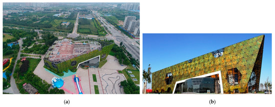
Figure 1.
Photos of the main exhibition hall: (a) Aerial view; (b) Elevation view.
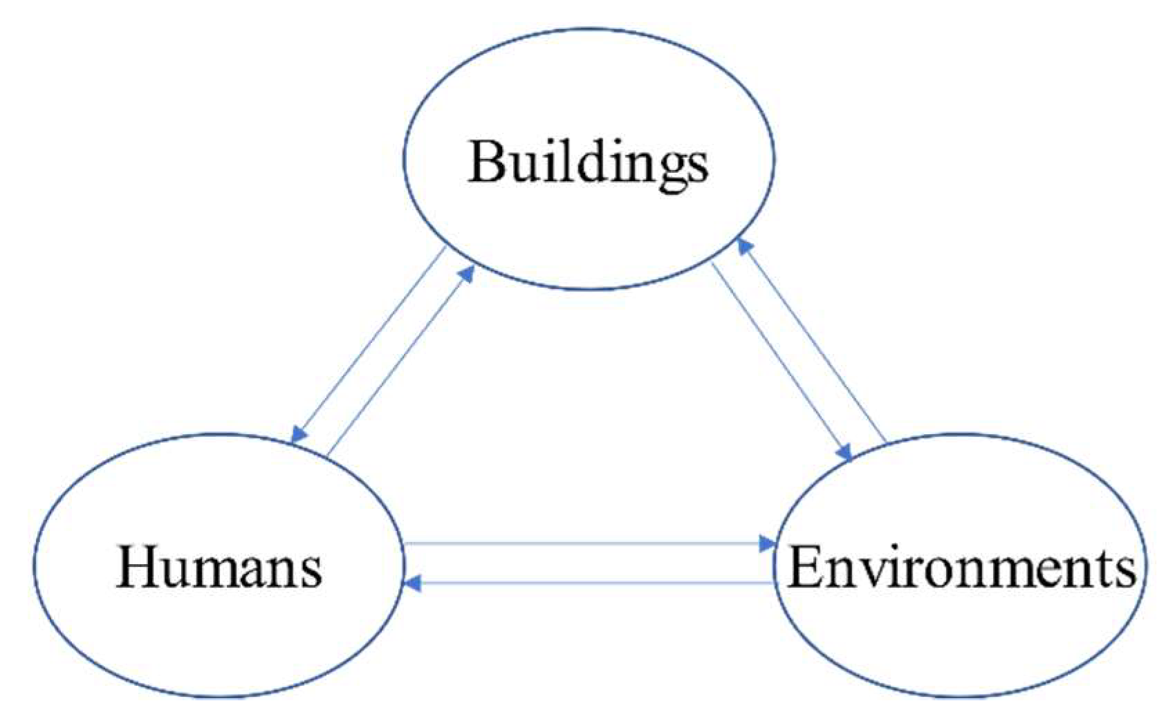
From a long-term perspective, the general design idea should be forward-looking and sustainable. Its connotation was up around the relation among “environments”, “buildings”, and “humans”, forming a synergy function in PBD as shown in Figure 2. “Equality and connectivity” were the core idea of the synergy during the design process, so these three subjects were treated equally, and the initiative of every subject was inspired.
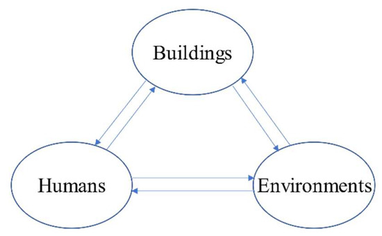
Figure 2.
Synergy among humans, buildings and the environment.
Then, information, construction knowledge, environmental, social and economic impacts [20] were taken into overall consideration since all these factors could address holistically the complexity of the urban landscape of the Expo park. And energy-efficiency and environmental harmony [21,22] were considered more to balance the relationships between humans and nature through the PBD method. This concerned the harmony of the whole territory that encircles the exhibition hall in the Expo Park, so maintaining ecological connectivity [23] was important to create a relationship to the outside. The initial design goals focused on four principles:
- Emphasize the harmony between buildings and the nature;
- Create healthy, comfortable working and viewing experience;
- Improve energy utilization efficiency;
- Improve the utilization efficiency of all aspects of buildings, such as exhibition partitions, interior circulation etc.
In the design process of the main exhibition hall, designers compiled traditional design approaches such as graphic statics to digital algorithms so as to conduct more complex computation and improve design efficiency with the help of computers. Grasshopper based on Rhino3D was used for parametric modeling for the structural design. Rhino3D as a tool for industrial design and computer-aided manufacturing (CAM), had advantages in operability and interaction, and it could easily exchange files with CAD. Rhino3D with good expansibility, was implemented by some programming languages such as VB and C++. The Rhino3D model of intersecting joints designed by parameterized Grasshopper was imported into Midas finite element analysis. Besides, the software Octopus combined the Pareto optimization principle and genetic algorithm, and it provided various interactive operations, convenient data storage, and data transmission function. Octopus plug-in with a higher degree of visualization presented the best overall solution, which was used for model optimization of the main exhibition hall by a multi-objective optimization analysis based on Grasshopper.
3. Digital Shape Generation Technology
The Hebei Garden Expo aimed to make architecture, nature, culture and history fuse together into a comprehensive viewing experience. So as a green building in the park, the main exhibition hall would achieve social and cultural sustainability. Building sustainability involves various relations between buildings, natural and social systems and therefore comprises a complex of different priorities. To cope with this complexity and to support sustainability, the systematic, holistic and practical approaches to building design was developed. The “function” is what buildings require for the future users, and its scientific engineering performances, and architectural aesthetic are presented by the “form”. The “form” of the main exhibition hall stemmed from the architectural concept and the optimization prepared by the structural designer. To find the best balance between “form” and “function”, is an iterative process of translating and achieving the performance requirements.
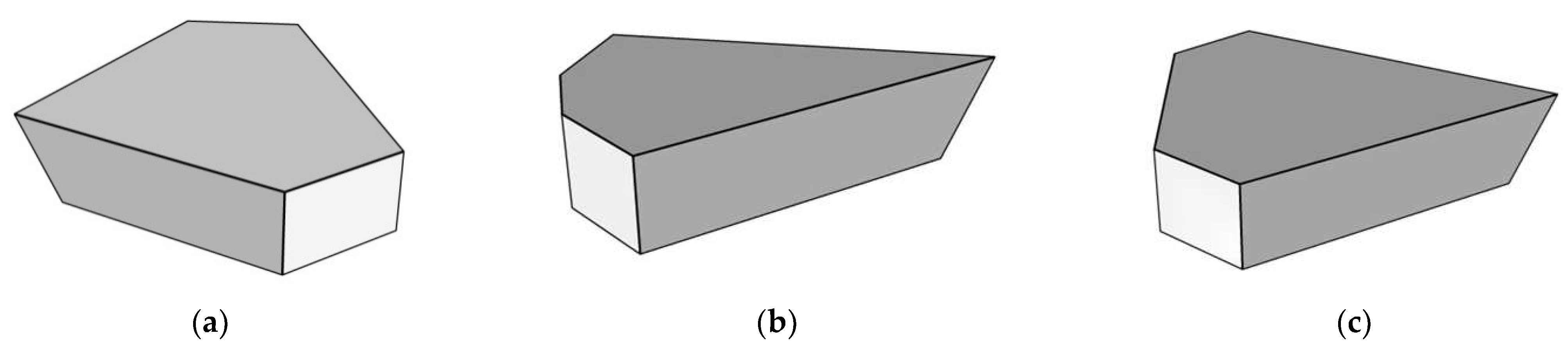
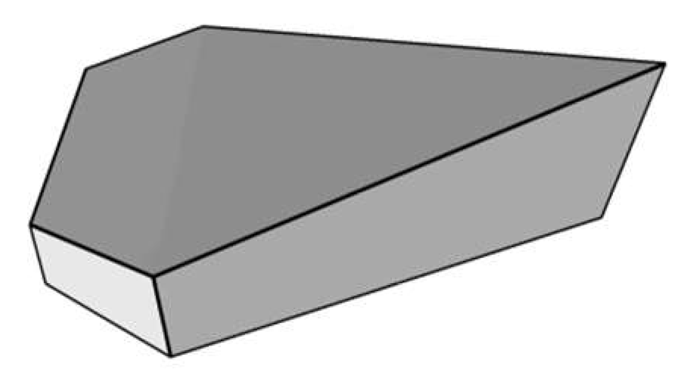
Alternative space arrangements with flat roofs were interpreted by adjusting some parameters such as the length of the major and minor axes, and the angle between adjacent facades. In accordance with the principle of north-south symmetry, three profiles were compared as shown in Figure 3. The main facade of Profile 1 deviated from the direction of the main gate, and the length-to-width ratio of Profile 2 was large, so Profile 3 looked reasonable. However, to fit with neighboring spaces, a tilted roof form from west to east was chosen, with the lowest point at 32 m and the highest point at 40 m, as shown in Figure 4. The height of the main exhibition hall was determined by rockeries, towers, and vegetation areas in the park, so the similar height made the building blend in its surroundings. The width was designed to be 146 m long in the east-west direction, 131 m long in the north-south direction. This building shape reduced the total construction area and enhanced the space sense like a diamond. It had been verified by tourists that the visual effect is stunning like a dazzling, precious, and rare diamond among green trees.

Figure 3.
Alternative space arrangements with flat roofs: (a) Profile 1; (b) Profile 2; (c) Profile 3.

Figure 4.
Final scheme with an inclined roof.
The next step of PBD was to study the layout of the entire building, which consisted of finding the best indoor arrangement to satisfy the geometric requirements [24]. Designers aimed to realize conservation and sustainable development [25] to construct the main exhibition hall as a green building. Combined with the actual architectural functions, a special double-skin structure was selected for the exhibition hall. A bright exterior glass curtain wall was separated from the RC structure, and it covered the concave of the interior RC structure. The glass‘s reflection to the around vegetation made the exhibition hall fit into the scenery so well, and this reflectivity of glass curtain walls produced a visual phantasmagoric effect. Meanwhile, the adoption of this structural form not only reduced the construction difficulty, but also considered the flexible utilization of the exhibition areas, and the reasonable utilization after the Garden Expo.
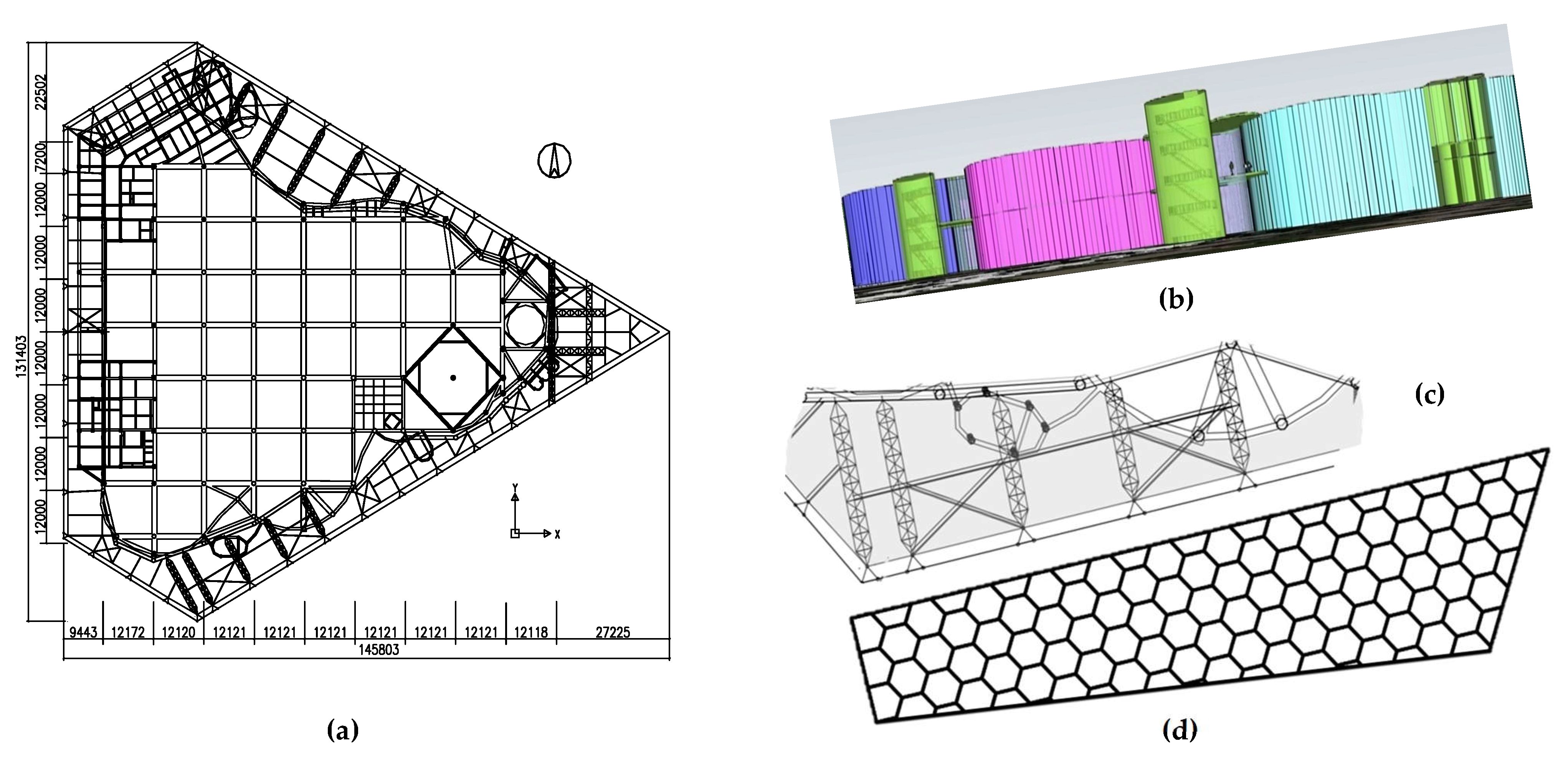
Figure 5 shows the general layout drawing of the main exhibition hall. The column grid of the main RC structure was distributed by the dimension of 12 m ×12 m, as shown in Figure 5a, and the equipment pipeline system was arranged orderly according to the column grid. The concept of “biological cells” was implanted into the design idea, meaning the origin and evolution of life, so the RC structure was formed by the superposition of multiple cells, as shown in the cell-shaped rooms in Figure 5b. The interlayer space between RC wall and the glass curtain wall is the shadowed area as shown in Figure 5c. The external glass curtain wall was chosen as a hexagon honeycomb-like structure as shown in Figure 5d. This is a comprehensive decision about the structure’s function, social benefit, aesthetic effect and building cost, which reflects the close cooperation and rich experience of structural engineers and architects. As shown in Figure 1a, a unique architectural form illustrated “the structure displays the beauty of architecture”.
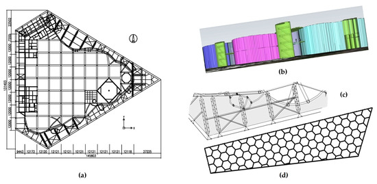
Figure 5.
General layout drawing: (a) Floor plan and layout of the column grid; (b) Cell-shaped rooms; (c) The interlayer space; (d) Exterior glass curtain wall.
4. Design of the Curtain Walls
4.1. Truss Design
Due to the unpredictability of environmental conditions and the significance of the environment in PBD, finite element modeling (FEM) using the MIDAS/Gen software was conducted as the most important feedback mechanism. In the simulation process, models were continuously optimized and problems could be solved in advance. This can foreseeably avoid many problems encountered by traditional architectural design and construction. In accordance with corresponding specifications and actual conditions, the basic parameters in the simulation were as follows: basic wind pressure once in 50 years, 0.35 kN/m2; basic snow pressure once in 50 years, 0.30 kN/m2; ground surface roughness, Class B; temperature difference, ±25 °C; seismic precautionary intensity, Degree 7; design acceleration of ground motion, 0.10 g; site category, Class III; seismic grade, Grade I.
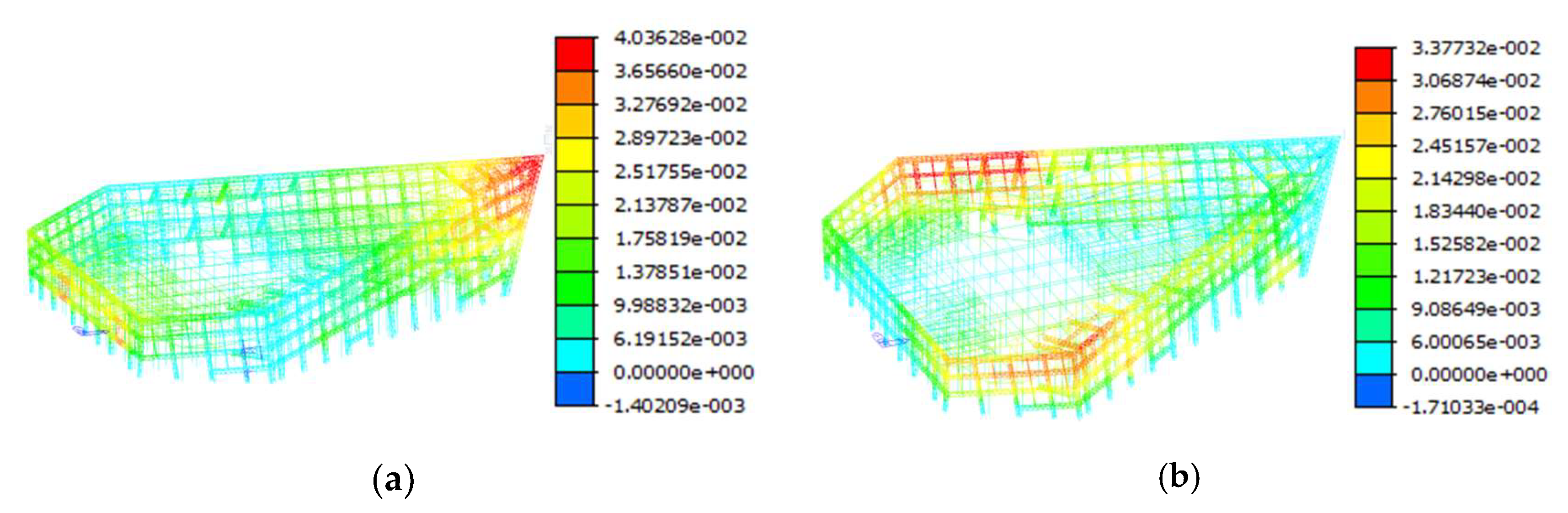
The horizontal displacement of the final overall structure model in Direction X is shown in Figure 6a. The maximum displacement and the minimum displacement, 40.36 mm and 21.37 mm, respectively appeared at the top of the eastern side and the top of the western side; the ratio of the maximum elastic horizontal displacement to the average elastic horizontal displacement was 1.31. The horizontal displacement of the overall structure in Direction Y is shown in Figure 6b. The maximum displacement and the minimum displacement, 15.26 mm and 6.00 mm, respectively, appeared at the top of the northern side and the top of the southern side; the ratio of the maximum elastic horizontal displacement to the average elastic horizontal displacement was 1.43. The plane torsion of the structure was irregular, but the ratio was still within 1.5, which met the specification requirements. The maximum elastic inter-story drift ratio in Direction X of 1/811, appeared at the lowest point of the top surface of steel truss, and the maximum elastic inter-story drift ratio in Direction Y of 1/651, appeared at the west of the north facade. Both of the maximum elastic inter-story drift ratios were much less than the specification limit of 1/250. Due to the complex and irregular structure, an elastic-plastic time history analysis was used to check the structural deformation under severe earthquakes. The elastic-plastic inter-story drift ratio was 1/163, which conformed to the specification limit of 1/50.

Figure 6.
Displacement nephograms of the structure: (a) Displacement nephogram in Direction X (Unit: m); (b) Displacement nephogram in Direction Y (Unit: m).
4.2. Design of Glass Curtain Walls
To show a braided fabric form and a silhouette effect, the grids of curtain walls were designed to be hexagons referring to the honeycomb in nature, as shown in Figure 7. The hexagonal unit grid on the curtain wall was divided into 12 same triangular subunits so as to design standardly. The components were convenient for manufacturing and the total cost was saved substantially.
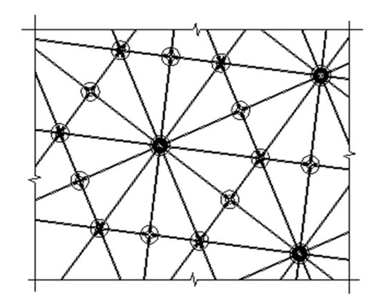
Figure 7.
Hexagonal grids on the curtain wall.
The grid division of the curtain wall was further deduced according to the outline of the main exhibition hall. A digital connection between the standard side length of the grid on the curtain wall of the main facade and the profile of the exhibition hall was established by the parametric technique. Since there were multiple combinations between segmentation length and the number of standard units, both Grasshopper and Octopus were used to improve the screening efficiency of parameters. Through some related battery components, the size and number of grids on the curtain wall was adjusted, and the specific layout of battery components on the curtain wall is shown in Figure 8. After 12 times of iterations, a very stable state was reached in the solving process, and a solution closed to the origin of the solution spatial coordinate (Figure 9) was defaulted as the optimal solution. In the front view of the solution space, the optimal solution for the grids on the curtain wall of the main facade was obtained after a reinstate solution was performed on the points near the origin. Afterwards, the parametric programs were used to slightly adjust the grid division and side length for other facades according to the layout of battery components (Figure 10), then the final optimal solution for grids on the overall curtain wall is shown in Figure 11.
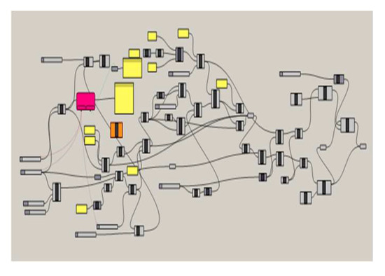
Figure 8.
Layout of battery components on the main facade.
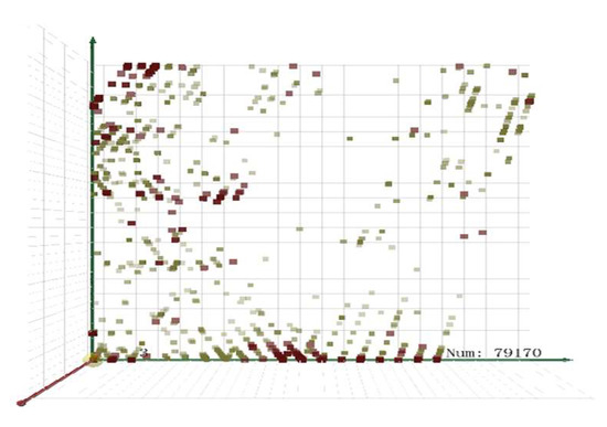
Figure 9.
Front view of the solution space.
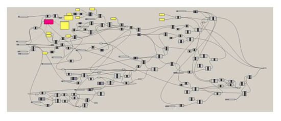
Figure 10.
Layout of battery components on other facades.
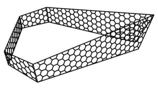
Figure 11.
Final grids of the overall curtain wall.
5. Optimum Design of Joints
5.1. Joint of Steel Tubular Trusses
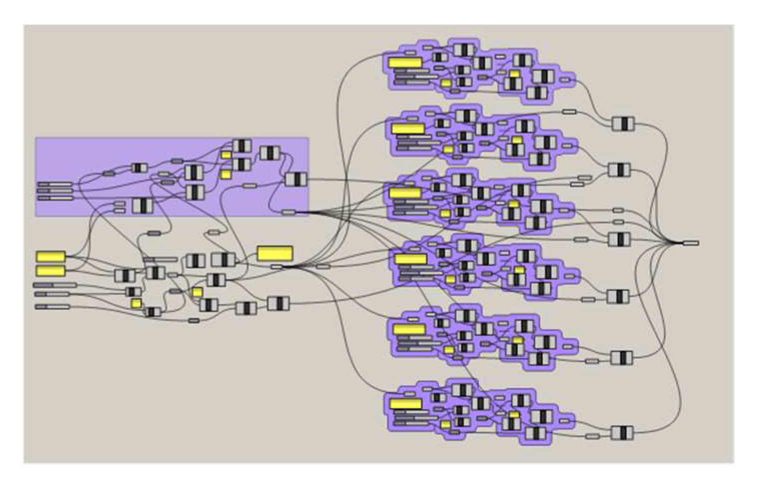
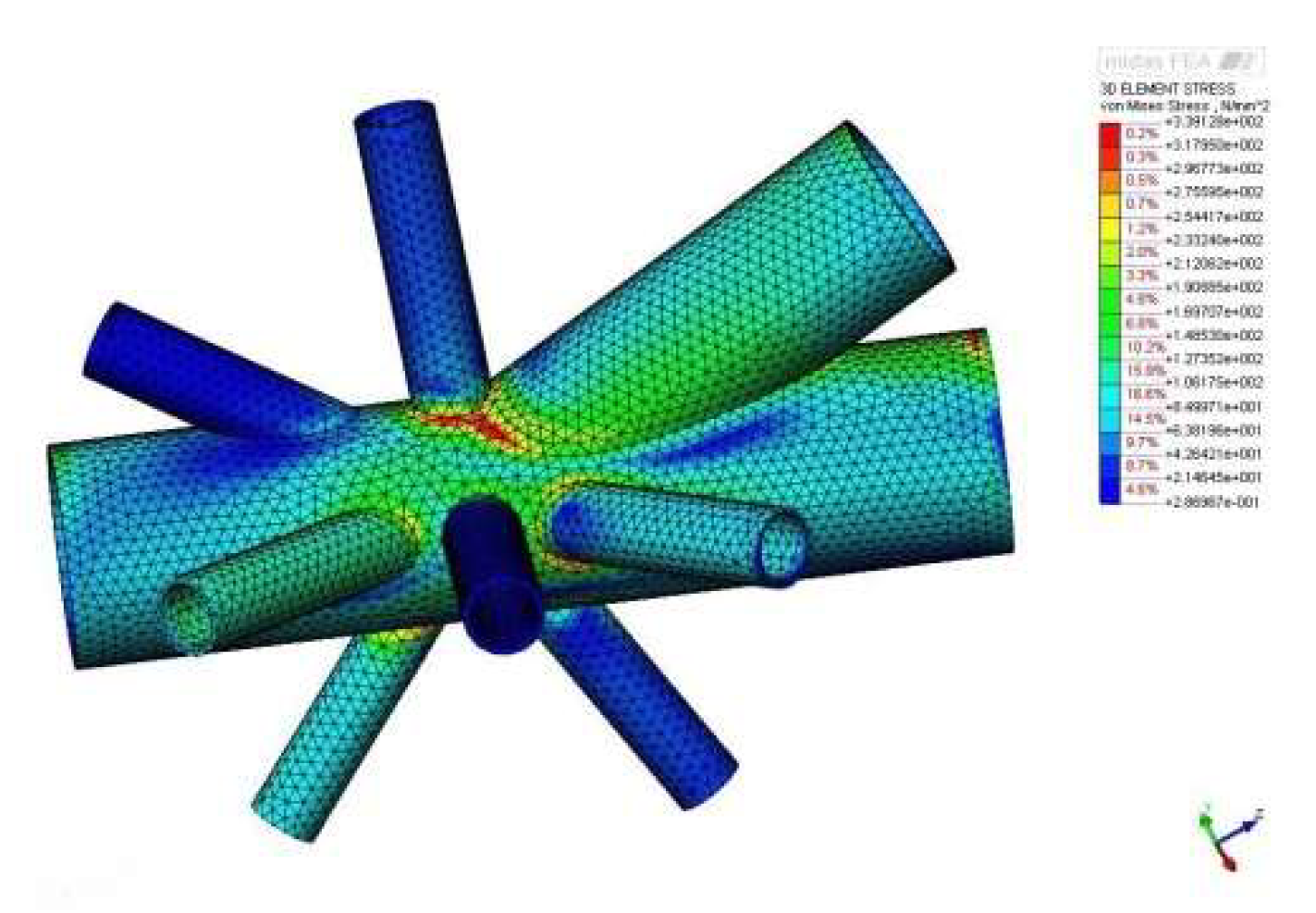
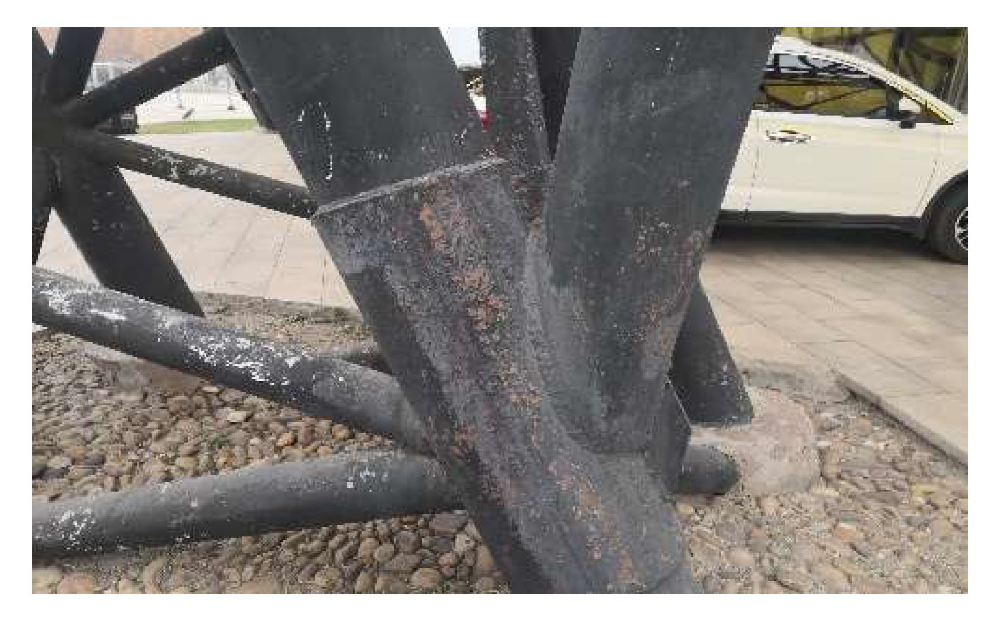
Using a multi-objective optimization analysis and an adaptive parametric design, the whole design process was quantifiable, traceable and multidisciplinary, and gradually evolved to the optimal solution in accordance with scientific logic between generality and individuality. The model of the intersectant steel tubular joint shown in Figure 12, was generated in accordance with the related battery components (Figure 13). The joint was arranged to adjust the diameter and wall thickness of the main steel tube, and the number and penetration angles of the branch tubes. The maximum stress in the non-optimized joint was 339 MPa under the ultimate load, as shown in Figure 14, which was larger than the design strength of 305 MPa. Then the joint was strengthened using a steel sleeve covering on the connection zone. The analysis result showed that the steel sleeve effectively reduced the stress concentration caused by the intersection of those branch tubes, and the corresponding stress nephogram is shown in Figure 15. The recent situation of the joint is photographed in Figure 16, and it can be seen that except for a little corrosion on the surface, there is no damage.
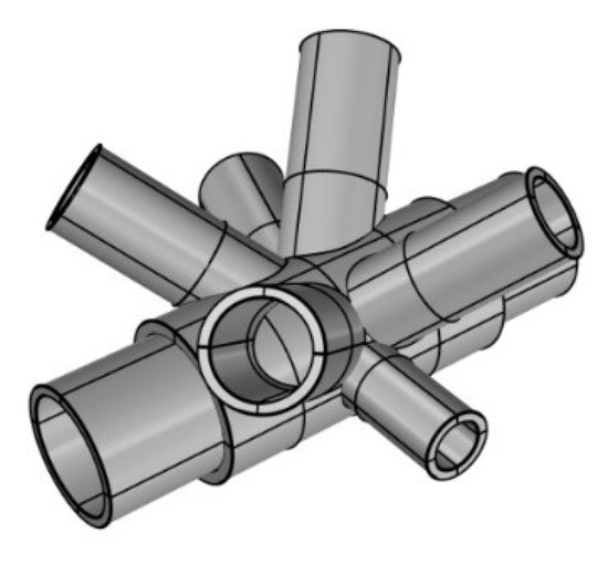
Figure 12.
Intersectant joint model.
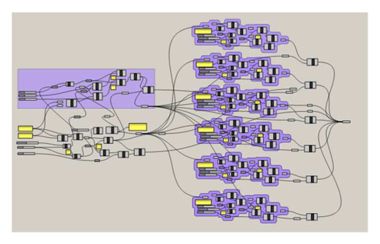
Figure 13.
Layout of battery components.

Figure 14.
Stress nephogram of the original joint.
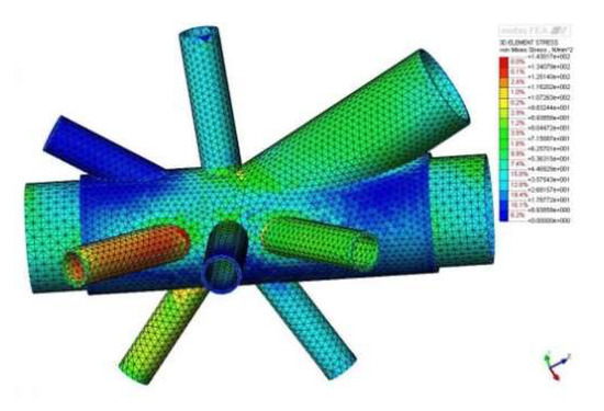
Figure 15.
Stress nephogram of the optimized joint.
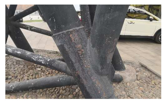
Figure 16.
Recent photograph of the joint.
5.2. Joint of Curtain Walls
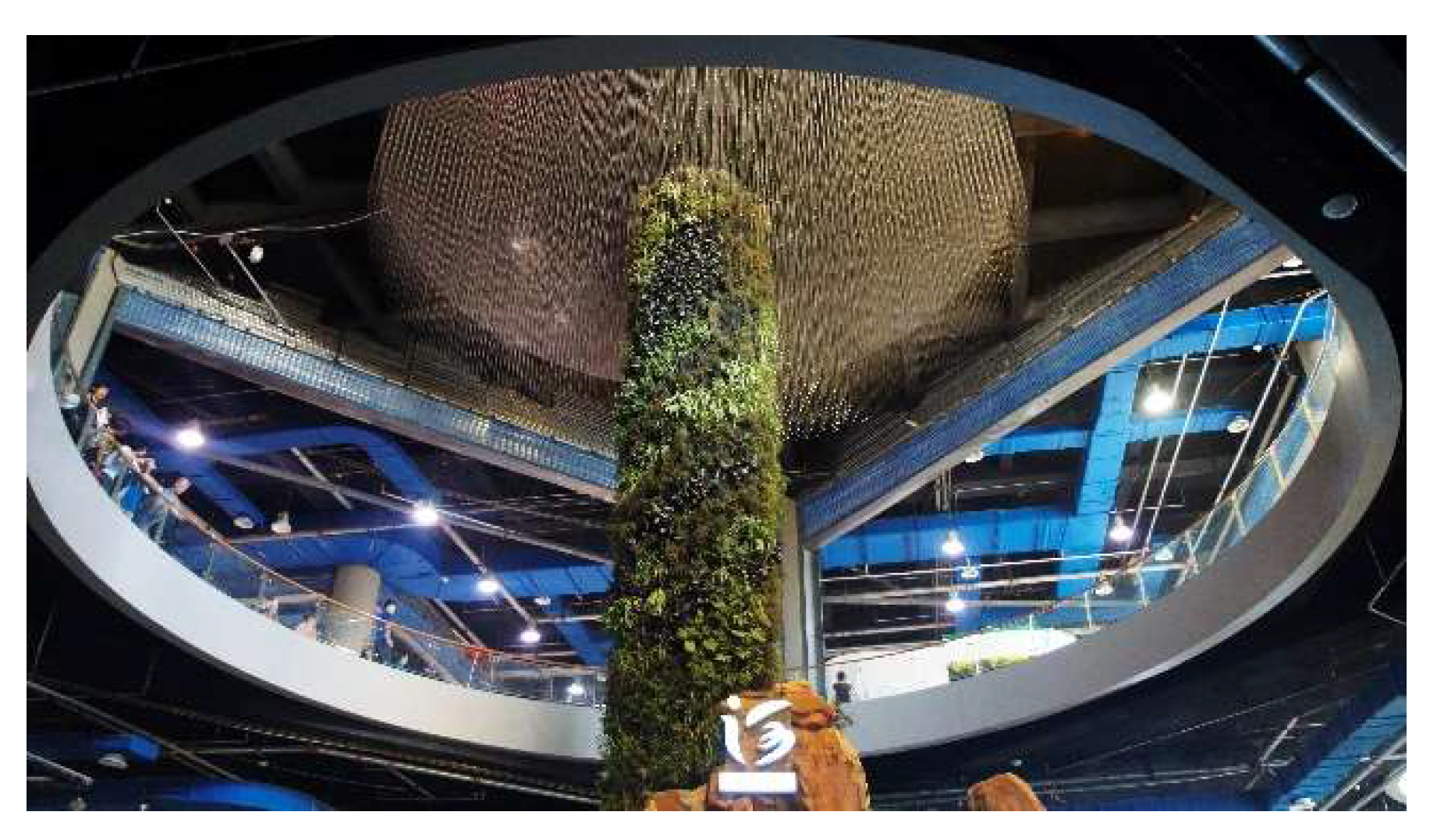
The biggest problem with the glass curtain wall was the glasses falling off, and the following reasons were drawn from other similar structures. (1) Larger deformation of the steel structure; (2) Infirm connection between the steel and glass; (3) The collapse of the glass itself. Then firstly, the deformation of the steel structure was effectively controlled within an acceptable range by FEM. Several joint forms on the glass curtain wall were designed (Figure 17a–c), which referred to the concept of “shaft”. Figure 17d shows the details of the keel. A circular tray and a round cap were used to eliminate the stress concentration in the connection and further to reduce the glass damage. And the buckle joint was adopted to ensure the connection quality. Besides, the glass with fewer impurities and better quality was put into application to prevent the probability of glass falling. The hexagonal grid after an optimal geometric iteration was a unified module on the curtain wall. The size of each divided triangle was the same, and the steel tubular truss met the design requirement for the hexagonal grid, which reduced the difficulty of construction. This joint form with a regular configuration resisted the load effectively. After 10 years of service, none of the glass fell off, no materials have been repaired or supplemented, and the recent photograph of the glass curtain wall is shown in Figure 18, presenting the same original state of the glass curtain wall.
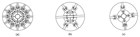
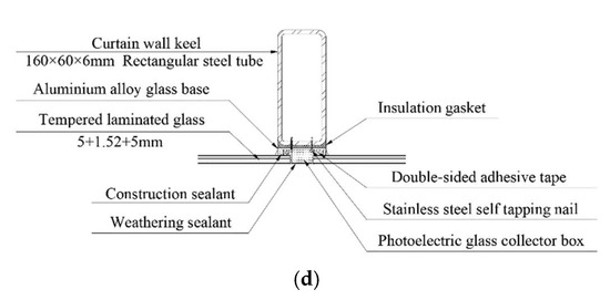
Figure 17.
Joint details of the curtain wall: (a) Joint I; (b) Joint II; (c) Joint III; (d) Keel drawing.
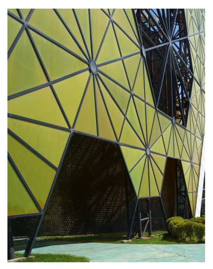
Figure 18.
Recent photograph of the curtain wall.
6. Ecological Connectivity
The sustainability of the built-environment is a complex subject in interrelated systems. The exhibition building in a park asked first of all for the identification of the ecological processes that link itself to its surroundings. In the last decade, ecological networks formed, which provided its ecological connectivity with the surrounding landscape situated in the peripheral region.
6.1. Extension of Space
The interlayer space (see Figure 5c) between the curtain wall and RC structure is similar to a double-skin cavity, which is semi-closed, as shown in Figure 19. The interior and exterior structures were smoothly connected by steel components. The glass curtain wall separated the interspaces from the environment, but good natural lighting made the interspaces act similarly as the outdoor space with a good light and shade effects. The openings on the curtain wall enriched the form of the entity, and the space on both sides of the curtain wall was linked. The glass curtain wall presented an adhesion area with functional links to the RC structure, and this extended space possessed vegetation of high ecological quality through grassland and tessellated green wall. Therefore, the RC structure was characterized by a very low green area, but through a hollowed-out semi-closed glass curtain structure, the interlayer space formed a transition towards the high-quality vegetation areas because the yellowish green glass wall was completely integrated into the surrounding environment. The urbanization processes of the main exhibition hall didn’t fragment the landscape, and the existing capability to transmit biological energy into the garden has still been kept.
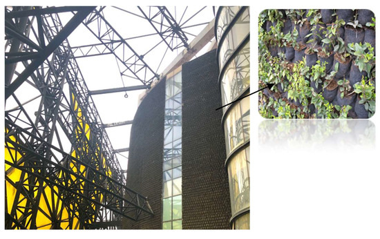
Figure 19.
Semi-closed interlayer space between RC structure and glass curtain wall.
The various internal systems of electrical, plumbing, and air-conditioning neither occupied indoor space, nor affected the normal operation of other indoor functions. And the regulating equipment was usually used for energy exchange between indoors and outdoors, so it was beneficial to shorten the distance to reduce energy dissipation. Existence of the transition area identified the contribution of different sites in the spatial arrangement, since the equipment pipeline was arranged orderly to integrate with the internal environment. As shown in Figure 20, the indoor space was neater and utilization was improved evidently under the condition of reduce of the equipment interference.

Figure 20.
Indoor space of the exhibition hall.
6.2. Interactivity Function
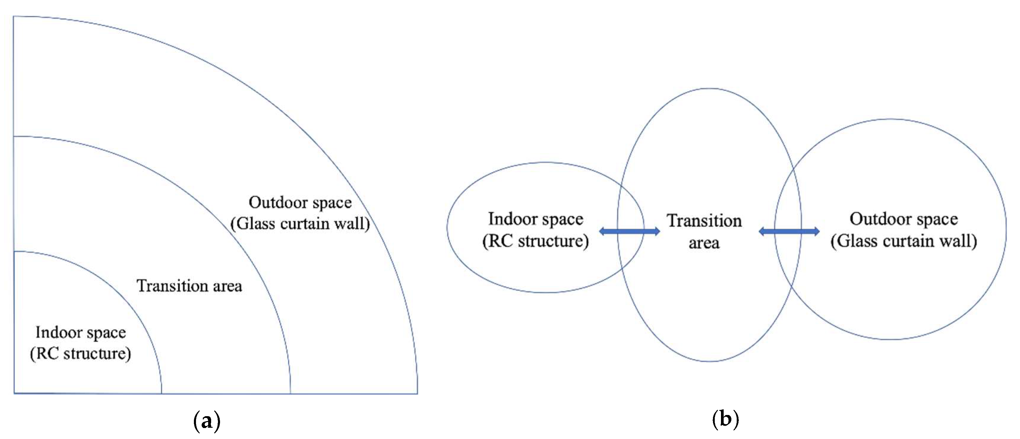
From the plane of the exhibition hall, it can be clearly seen that different functional spaces were arranged around different arcs according to the specific function, and the rim of the arc was enclosed by the straight curtain wall. The cavity space emphasized the overall volume and the boundary between the two interfaces. This transition area was in some ways a corridor, following the principle of spatial conservation [26]. Such a corridor design can decide spatial conservation programs, and it also provided a rather simplistic appreciation of regional ecological processes [27]. For the exhibition hall, the corridor was an extended place for indoor functions and activities, and the uncertain utilization of the cavity and the interaction with indoor space made the exhibition area more diversified and integrated. The function of the corridor may mostly be a leisure area or a unique exhibition area. As shown in Figure 21, people’s activity, equipment placement, or air ventilation can exchange among the indoor space, the transition area, and the outdoor space, which reflected the idea of “connectivity” in PBD concept. As shown in Figure 21b, the cell-shaped RC structure utilized room doors and evacuation stairs to share some space with the transition area, and the semi-closed glass curtain wall formed a natural sharing space with the outdoor area.
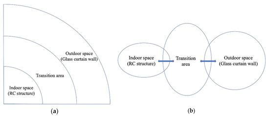
Figure 21.
Relationship between indoor space, transition area, and outdoor space: (a) Spatial relationship between main structure, transition area, and glass curtain wall; (b) Functional relationship between indoor space, transition area, and outdoor space.
A tessellated green wall was installed on the exterior RC wall, and the whole corridor was covered with green grass, forming an interlayer green space, as shown in Figure 22. It can be seen in the picture that the tessellated green wall as a background wall and plant murals perfectly combined with the plane greening in the garden. The glass curtain wall was hollowed out at different elevations. In particular, animal passageways were set at the lowest layer to make the environment more ecological, then vegetation was continuous on the ground. The animal passage was conducive to create an environment where animals passed or lived, relieving the survival pressure brought by human activities to animals, forming a harmonious coexistence among human, animals and nature. The existence of the tessellated green wall and the animal passageway enabled urban animals, such as squirrels and birds, to stay and nest on the building wall. Together with the reflection of glass curtain walls, these design details improved the territorial coherence between the exhibition hall and its surrounding landscapes, so there were no evident edge effects in order to maintain effective ecological process zones [28,29]. Therefore, the exhibition hall has been further in accord with the theme of the Garden Expo of “equality and connectivity”, since the “interactivity” well interpreted the architecture function and structure form of the main exhibition hall.
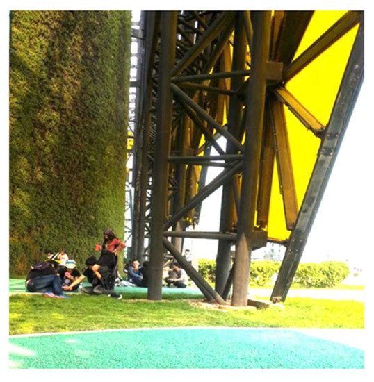
Figure 22.
Interlayer green space.
6.3. Energy Utilization Efficiency
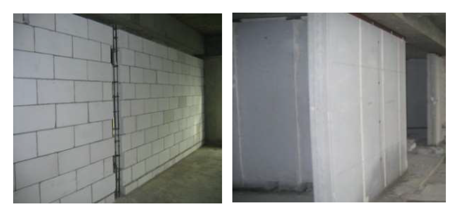
Achieving sustainable goals in the buildings requires that it is both energy efficient and able to improve the indoor environment. The double-skin structure showed obvious advantages in ventilation, sound insulation, natural lighting, and energy conservation. First, the glass curtain wall played a good role in shading, reducing the window area and window-to-wall ratio. Second, the tessellated green wall was conducive for energy saving. It was found that when the outdoor temperature was 38 °C, the outer wall temperature of RC wall with green plants was 27 °C, which really conformed to the modern concept of energy saving and environmental protection. Thirdly, autoclaved aerated concrete (AAC) was used to achieve thermal insulation, as shown in Figure 23. Besides, the energy-saving gas-permeable coating was painted on the wall, and shells, soil, and rocks were integrated into the inner wall of the exhibition hall to present diverse hues. These measures not only saved materials but also protected environment. Besides, the painted coatings had the particular technical features to let the water evaporate, so avoid moisture condensation inside the building.
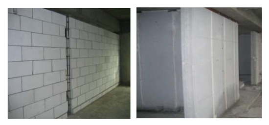
Figure 23.
Thermal-insulation building blocks using AAC and board walls.
The digital simulation has become the most direct approach to connect architectural concepts and building entities. The practice testified that the simulation results coincided with the actual situation. Since 2011, the main exhibition hall has experienced gale, hail, and other extreme weather, but there was no structural damage. It showed that the special double-skin structure of the main exhibition hall took into account the requirements of form and function. As time passed, the internal force caused by initial construction errors and fabrication imperfections for the steel tubular truss became almost stable, and the stress concentration in the steel tubular truss has decreased, so there was no influence of structure displacement change, showing the self-repair capability of the structure. However, the building structure form of double skin was very expensive, and the investment cost increased greatly, so it is not recommended to use double skin for a small buildings. As for the main exhibition hall in an Expo park, the double-layer skin was suitable in the open and flat landscape. The main exhibition hall achieved the synergy of architecture function and structure form in PBD, so ecological connectivity has been identified to promote ecological quality all around its territory. A suitable ecological niche formed by the main exhibition hall integrated the inorganic artificial environment with the organic natural environment, providing the visitors with an experience related to the surrounding scenery as well as the building itself.
7. Conclusions
This paper was to describe the design process and building implementation issues, which the PBD concept was successful used in making the exhibition hall more sustainable within the context of the first Hebei Garden Expo. In line with the efforts of architectural and structural engineers, the main exhibition hall was a successful construction project which provided its ecological connectivity with the surrounding landscape situated in the peripheral region:
(1) The construction project of main exhibition hall adopted a special structure selection of double-skin structure type, and corresponding structural functions were met. The architectural concept and functions were achieved through the diamond-shaped glass curtain wall and the cell-shaped RC structure. The transition area of the special double skins provided extension of space and satisfied the function of interactivity; energy conservation was also easily achieved for the green infrastructure, so the core idea of ecological connectivity and equality with the surrounding landscape was reflected. The principles of “equality and connectivity” in the PBD confirmed the original intention and the environmental performance for the exhibition hall. Over the last decade, there has been little structural damage, and urbanization and the construction of transport networks near the garden park have not influenced it to still be a landmark building in Shijiazhuang.
(2) Our examination illustrates a performance-based design of complexity and uncertainty concerning the ecological processes, such an infrastructure design could greatly strengthen the links between the built and natural environment and thereby provide more effective spatial landscape planning. In case that buildings, environments, and humans were equally treated, the construction can promote the realization of sustainable strategic initiatives in the built environment, and realize green buildings, safe and healthy lives surroundings.
Author Contributions
Conceptualization, Y.Z. and S.C.; methodology, H.B.; software, X.Z.; investigation, H.B.; resources, S.C.; writing—original draft preparation, H.B.; writing—review and editing, Y.Z.; project administration, S.C.; funding acquisition, Y.Z. All authors have read and agreed to the published version of the manuscript.
Funding
This research was funded by the National Natural Science Foundation of China (grant number 52078179).
Institutional Review Board Statement
The study did not involve humans or animals.
Informed Consent Statement
The study did not involve humans.
Data Availability Statement
The data used to support the findings of this study are available from the corresponding author upon request.
Conflicts of Interest
The authors declare no conflict of interest.
References
- Jeon, H.; Lee, K. A Direction of Urban Planning on the Waterfront for Public through Corresponding with Climate Change—A Case Study on the Design Competition in New York and Boston. J. Archit. Inst. Korea Plan. Des. 2015, 31, 39–50. [Google Scholar] [CrossRef]
- Sayın, S.; Celebi, G. A practical approach to performance-based building design in architectural project. Build. Res. Informat. 2020, 48, 446–468. [Google Scholar] [CrossRef]
- Meacham, B.J. Accommodating innovation in building regulation: Lessons and challenges. Build. Res. Informat. 2010, 38, 686–698. [Google Scholar] [CrossRef]
- Astarini, S.D.; Utomo, C. Performance-Based Building Design of High-Rise Residential Buildings in Indonesia. Sustainability 2020, 12, 7103. [Google Scholar] [CrossRef]
- Oxman, R. Performance-based design: Current practices and research issues. Int. J. Archit. Comput. 2008, 6, 1–17. [Google Scholar] [CrossRef]
- Ercan, B.; Elias-Ozkan, S.T. Performance-based parametric design explorations: A method for generating appropriate building components. Design Stud. 2015, 38, 33–53. [Google Scholar] [CrossRef]
- Lu, W.; Lv, X. Seismic analysis and performance-based design of a tall twin-tower beyond code limits with high-rise podium for Wuhan Ren Xin Hui. Build. Struct. 2016, 46, 12–19. (In Chinese) [Google Scholar]
- Yuan, F.; Zhu, W.; Gao, W. Why performative struction? Archit. Tech. 2019, 9, 8–14. (In Chinese) [Google Scholar]
- Szigeti, F.; Davis, G. Performance Based Building: Conceptual Framework; CIB: Amsterdam, The Netherlands, 2005. [Google Scholar]
- Seshadhri, G.; Paul, V.K. User requirement related performance attributes for government residential buildings. J. Facil. Manag. 2017, 15, 409–422. [Google Scholar] [CrossRef]
- Selim, S.; Demir, N. Analysis of landscape patterns and connectivity between tree clusters derived from lidar data. Fresenius Environ. Bull. 2018, 27, 3512–3520. [Google Scholar]
- Monaco, R.; Negrini, G.; Salizzoni, E.; Soares, A.J.; Voghera, A. Inside-outside park planning: A mathematical approach to assess and support the design of ecological connectivity between Protected Areas and the surrounding landscape. Ecol. Eng. 2020, 149, 105748. [Google Scholar] [CrossRef]
- Mathews, F. Conservation and self-realization: A deep ecology perspective. Environ. Ethics 1988, 10, 347–355. [Google Scholar] [CrossRef]
- Lee, W.H.; Abdullah, S.A.; Nor, S.B.M. Land use and landscape pattern changes on the inside and outside of protected areas in Urbanizing Selangor state, Peninsular Malaysia. Landsc. Ecol. 2019, 12, 41–63. [Google Scholar] [CrossRef] [Green Version]
- Passer, A.; Wall, J.; Kreiner, H.; Maydl, P.; Höfler, K. Sustainable buildings, construction products and technologies: Linking research and construction practice. Int. J. Life Cycle Assess. 2015, 20, 1–8. [Google Scholar] [CrossRef]
- Vimal, R.; Mathevet, R.; Thompson, J.D. The changing landscape of ecological networks. J. Nat. Conserv. 2012, 20, 49–55. [Google Scholar] [CrossRef]
- Mustafa, F.A. Performance assessment of buildings via post-occupancy evaluation: A case study of the building of the architecture and software engineering departments in Salahaddin University-Erbil, Iraq. Front. Archit. Res. 2017, 6, 412–429. [Google Scholar] [CrossRef]
- Olawumi, T.O.; Chan, D.W.M. Concomitant impediments to the implementation of smart sustainable practices in the built environment. Sustain. Prod. Consum. 2020, 21, 239–251. [Google Scholar] [CrossRef]
- Hansen, A.J.; DeFries, R. Ecological Mechanisms linking Protected areas to Surrounding Lands. Ecol. Appl. 2007, 17, 974–988. [Google Scholar] [CrossRef]
- Kuster, C.; Hippolyte, J.L.; Rezgui, Y. The UDSA ontology: An ontology to support real time urban sustainability assessment. Adv. Eng. Softw. 2020, 140, 102731. [Google Scholar] [CrossRef]
- Capeluto, I.G.; Ben-Avraham, O. Assessing the green potential of existing buildings towards smart cities and districts. Indoor Built Environ. 2016, 25, 1124–1135. [Google Scholar] [CrossRef]
- Liu, Z.; Chi, Z.Y.; Osmani, M.; Demian, P. Blockchain and Building Information Management (BIM) for Sustainable Building Development within the Context of Smart Cities. Sustainability 2021, 13, 2090. [Google Scholar] [CrossRef]
- Gobattoni, F.; Lauro, G.; Monaco, R.; Pelorosso, R. Mathematical models in landscape ecology: Stability analysis and numerical tests. Acta Appl. Math. 2013, 125, 173–192. [Google Scholar] [CrossRef] [Green Version]
- Rodrigues, E.; Fernandes, M.S.; Gomes, A.; Gaspar, A.R.; Costa, J.J. Performance-based design of multi-story buildings for a sustainable urban environment: A case study. Renew. Sust. Energ. Rev. 2019, 113, 109243. [Google Scholar] [CrossRef] [Green Version]
- Du, W.W.; Penabaz-Wiley, S.M.; Njeru, A.M.; Kinoshita, I. Models and approaches for integrating protected areas with their surroundings: A review of the literature. Sustainability 2015, 7, 8151–8177. [Google Scholar] [CrossRef] [Green Version]
- Lindenmayer, D.; Hobbs, R.J.; Montague-Drake, R.; Alexandra, J.; Bennett, A.; Burgman, M.; Cale, P.; Calhoun, A. A checklist for ecological management of landscapes for conservation. Ecol. Lett. 2008, 11, 78–91. [Google Scholar] [CrossRef] [PubMed]
- Thompson, J.D.; Mathevet, R.; Delanoë, O.; Gil-Fourrier, C.; Bonnin, M.; Cheylan, M. Ecological solidarity as a conceptual tool for rethinking ecological and social interdependence in conservation policy for protected areas and their surrounding landscape. Comptes Rendus Biol. 2011, 334, 412–419. [Google Scholar] [CrossRef]
- Mathevet, R.; Thompson, J.D.; Folke, C.; Chapin, F.S. Protected areas and their surrounding territory: Socioecological systems in the context of ecological solidarity. Ecol. Appl. 2016, 26, 5–16. [Google Scholar] [CrossRef]
- Turner, M.G. Landscape Ecology: The effect of pattern on process. Annu. Rev. Ecol. Syst. 1989, 20, 171–197. [Google Scholar] [CrossRef]


Publisher’s Note: MDPI stays neutral with regard to jurisdictional claims in published maps and institutional affiliations. |
© 2021 by the authors. Licensee MDPI, Basel, Switzerland. This article is an open access article distributed under the terms and conditions of the Creative Commons Attribution (CC BY) license (https://creativecommons.org/licenses/by/4.0/).