Article

Improvement of Temperature and Humidity Control of Proton Exchange Membrane Fuel Cells

1
College of Energy Engineering, Zhejiang University, Hangzhou 310027, China
2
College of Mechanical Engineering, Zhejiang University, Hangzhou 310027, China
3
College of Mechanical Engineering, University of Delaware, Newark, DE 19717, USA
*
Author to whom correspondence should be addressed.
Sustainability 2021, 13(19), 10578; https://doi.org/10.3390/su131910578
Submission received: 19 August 2021 / Revised: 17 September 2021 / Accepted: 17 September 2021 / Published: 24 September 2021
(This article belongs to the Special Issue Advanced Clean Energy Systems)

Abstract

:
Temperature and humidity are two important interconnected factors in the performance of PEMFCs (Proton Exchange Membrane Fuel Cells). The fuel and oxidant humidity and stack temperature in a fuel cell were analyzed in this study. There are many factors that affect the temperature and humidity of the stack. We adopt the fuzzy control method of multi-input and multi-output to control the temperature and humidity of the stack. A model including a driver, vehicle, transmission motor, air feeding, electrical network, stack, hydrogen supply and cooling system was established to study the fuel cell performance. A fuzzy controller is proven to be better in improving the output power of fuel cells. The three control objectives are the fan speed control for regulating temperature, the solenoid valve on/off control of the bubble humidifier for humidity variation and the speed of the pump for regulating temperature difference. In addition, the results from the PID controller stack model and the fuzzy controller stack model are compared in this research. The fuel cell bench test has been built to validate the effectiveness of the proposed fuzzy control. The maximum temperature of the stack can be reduced by 5 °C with the fuzzy control in this paper, so the fuel cell output voltage (power) increases by an average of approximately 5.8%.

1. Introduction

In order to cope with increasing energy and environmental problems, fuel cells have become famous alternative energy sources for the next generation. Fuel cells have the advantages of high efficiency, low noise, and no environmental pollution. Electricity generation does not go through the combustion process, and the efficiency can reach about 45% [1,2]. Electrochemical heat, steam condensation heat, and ohmic heating are the sources of heat generation in fuel cells [3]. Moreover, 80–90% of heat is generated in the catalyst layer on the cathode side. PEMFCs operate at relatively low temperatures (60–80 °C). Inappropriate thermal management leads to different thermal problems. Among them, two basic problems such as membrane drying and cathode flooding can be mentioned.
Temperature is one of the most important factors affecting the performance of fuel cells, and PEMFCs can have an energy efficiency of 40–60% when the operating temperature is stable at 60 to 80 °C. When the operating temperature of the stack is too low, the impedance of the stack increases, so the overall performance and efficiency of the stack decreases; when the operating temperature of the stack is too high, it will lead to the dehydration of the proton exchange membrane. Therefore, in order to maintain a stable working temperature, it is necessary to discharge the waste heat from the stack by a thermal management system.
The conductivity of the proton exchange membrane is closely related to the water content. Improper water management can lead to membrane drying or flooding, causing degradation of performance and durability. If the water content of the membrane is too small, the mass transfer resistance will increase; excessive water will cause the phenomenon of “water flooding”, block the diffusion channels of the reactant gas and seriously affect the performance of the fuel cell.
The thermal management of the fuel cell system should consider not only the cooling of the stack, but also the possibility of heat recovery. In this regard, additional devices must be used, such as air-to-air heat exchangers, humidifiers or condensers. They use part of the enthalpy of the exhaust gas and coolant at the cathode outlet, especially the enthalpy wheel in the heat exchanger. These components are mainly responsible for transferring heat, but they also allow the exchange of moisture. They are very compact and can achieve high energy transmission efficiency. It consists of a cylinder of gas-permeable material (polymer, aluminum or synthetic fiber) with a large surface area, which is necessary for sensible heat transfer. The driving force for the exchange is the thermal gradient between the relative airflows.
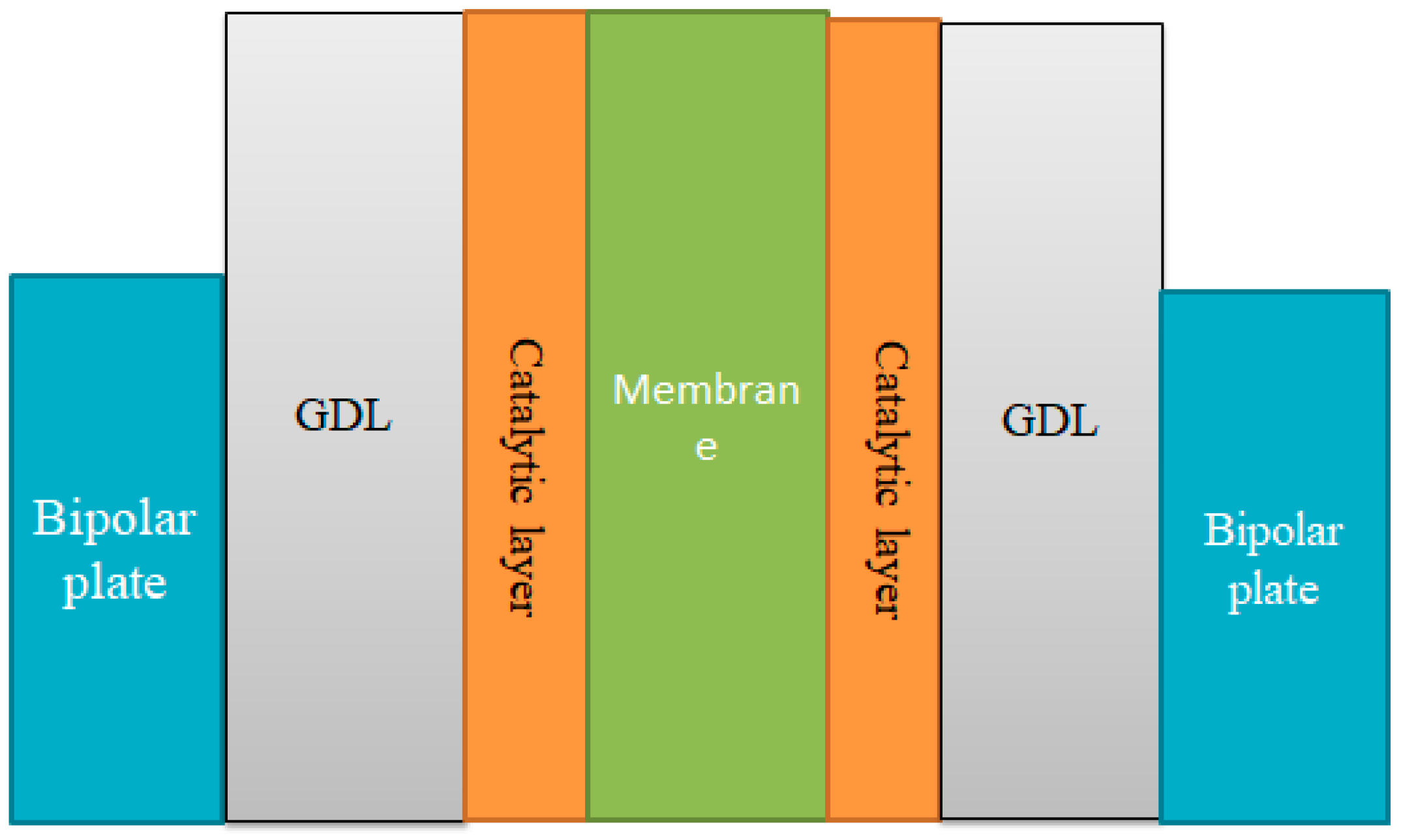
The main components of proton exchange membrane fuel cells are the anode, the cathode, the proton exchange membrane, the gas diffusion layer (GDL) and the catalyst layer in Figure 1. The voltage of a single fuel cell is generally around 1.2 V [4]. To achieve the desired voltage and power, a suitable single cell needs to be connected in series. The stack used in fuel cell vehicles is generally composed of hundreds of single cells. A complete fuel cell system includes the stack, the hydrogen supply, the oxygen supply system, the humidification system and the thermal management system.
The actual output voltage of the fuel cell is mainly composed of four parts [5,6,7,8]: Nernst open circuit voltage (E0), activated polarization voltage (Vact), concentration polarization voltage (Vconc) and ohmic polarization voltage (Vohm). The voltage is calculated as follows:
V = E 0 V a c t V o h m V c o n c
(1) Activated polarization overvoltage is generated during the process of mobile electrons forming a chemical bond between the cathode and anode, which can be expressed as:
V a c t = x 1 + x 2 T f c + x 3 T f c ln ( C O 2 ) + x 4 T f c ln ( I s t )
Among them, x1, x2, x3 and x4 are the fuel cells’ empirical constants related to the operating temperature and the air excess coefficient. In this article, x1 is −0.95; x2 is 0.003; x3 is 7.1 × 10⁻⁵; and x4 is −1.85 × 10⁻⁵. I s t is the stack working current. C O 2 is the dissolved concentration of oxygen at the gas–liquid interface. T f c is the temperature of the fuel cell.
In summary, the activation polarization overvoltage of the fuel cell is related to the temperature, the air excess coefficient and the current magnitude.
(2) Concentration polarization overvoltage can be expressed as:
V c o n = a ln ( 1 i i max )
where a is related to temperature and excess air coefficient. In this article, a is 0.0129 on the anode side and 0.0064 on the cathode side. i max is the maximum current density. i is the current density
In summary, the concentration polarization overvoltage of the fuel cell is related to the current density, temperature and excess air coefficient.
(3) The Ohmic overvoltage in the stack is calculated as:
V o h m = I s t × R
Among them, R is the single cell membrane impedance, Ω. In this article, R is 0.3, known by the law of resistance:
R = ρ × l A s t
In the formula, ρ —membrane resistivity is related to the water content, current and activation area of the membrane;
l —Thickness of the proton exchange membrane;
A s t —Activated area of single cell;
In summary, the ohmic overvoltage of the fuel cell is related to the magnitude of the current, the membrane water content and the membrane thickness.
Jang [9] found that gas humidification temperature, cell temperature and gas flow rate are the key operating conditions affecting the performance of fuel cells. Lobato [10] found that the improvement of stack performance depends on the temperature. High temperature can cause the proton exchange membrane to become dry or even dehydrated. Corinna [11] found that the temperature had a strong influence on the wettability and proton conductivity of the stack, but had little effect on the average voltage of the stack. According to Rodatz [12], the uneven temperature in the stack will increase the resistance of the gas and cooling water channels and form a localized hot zone. Seok-Ho Seo [13] found that the control of the amount of liquid water by adequate cooling fuel cell system in the GDL layer is very important for the stable and reliable operation of PEMFCs. Srinivasan Raman [14] discussed the model-based control strategies by maintaining the humidification to avoid drying and flooding. Stephan Strahl [15] developed a controller with a simple structure, and a good closed-loop behavior to serve for further temperature and humidity control studies of PEMFC systems.
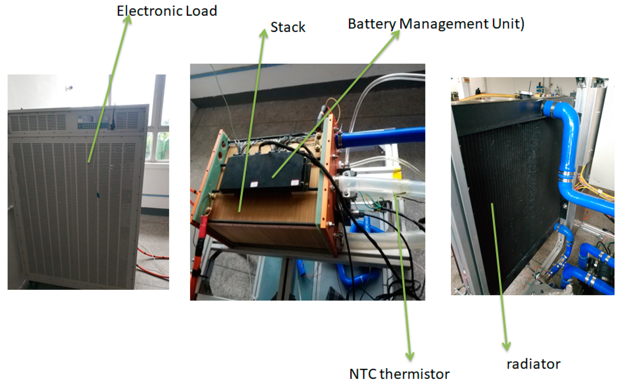
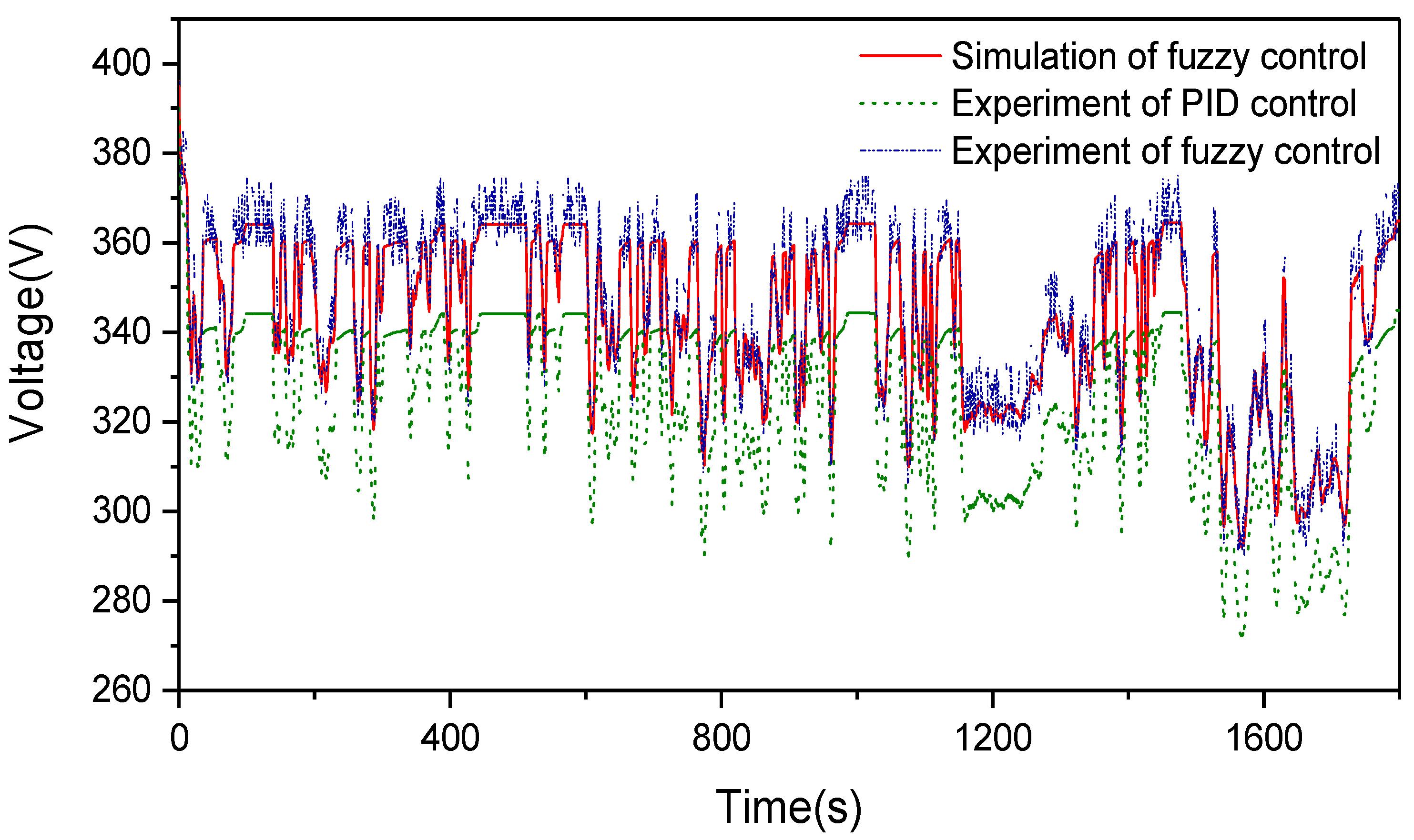
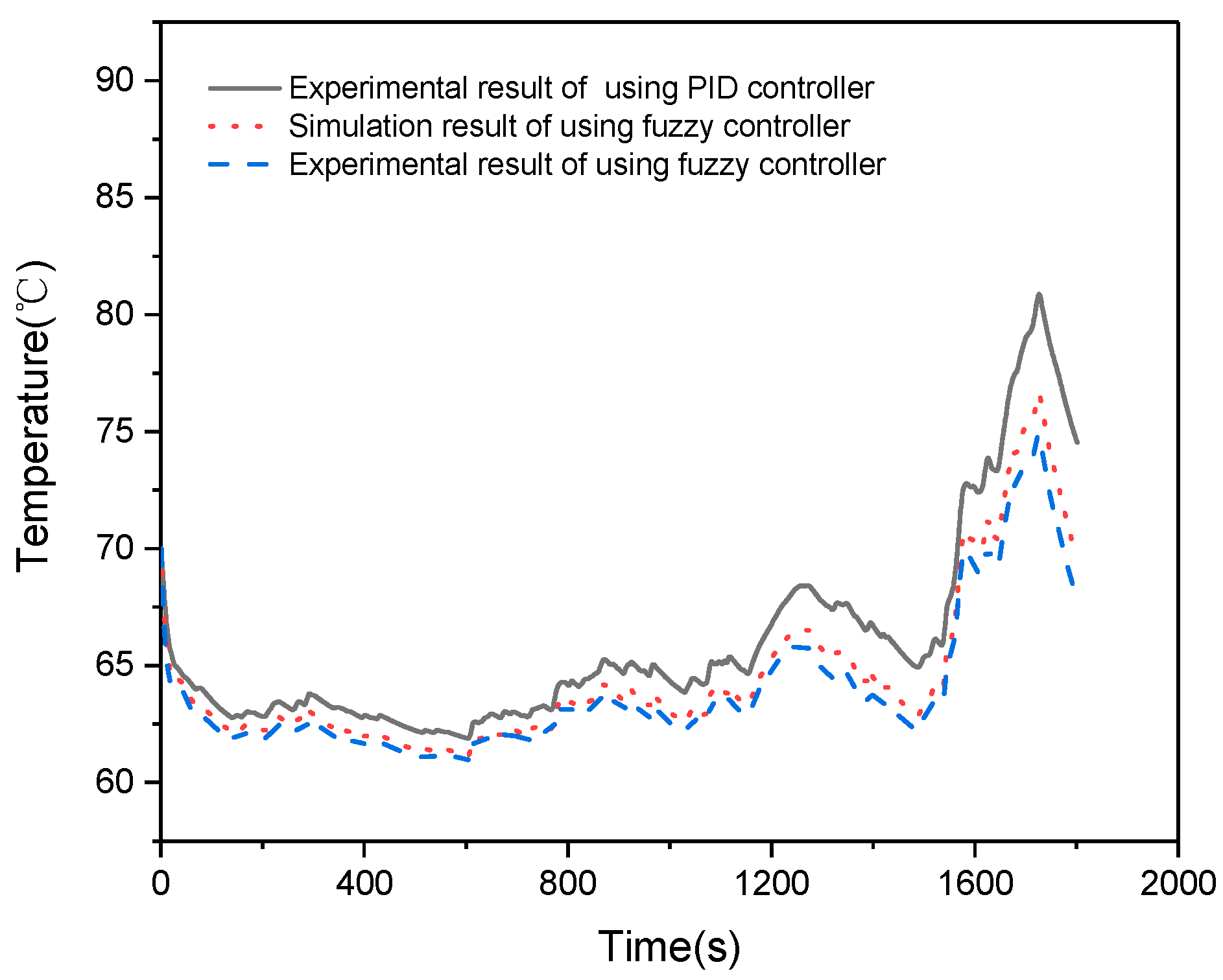
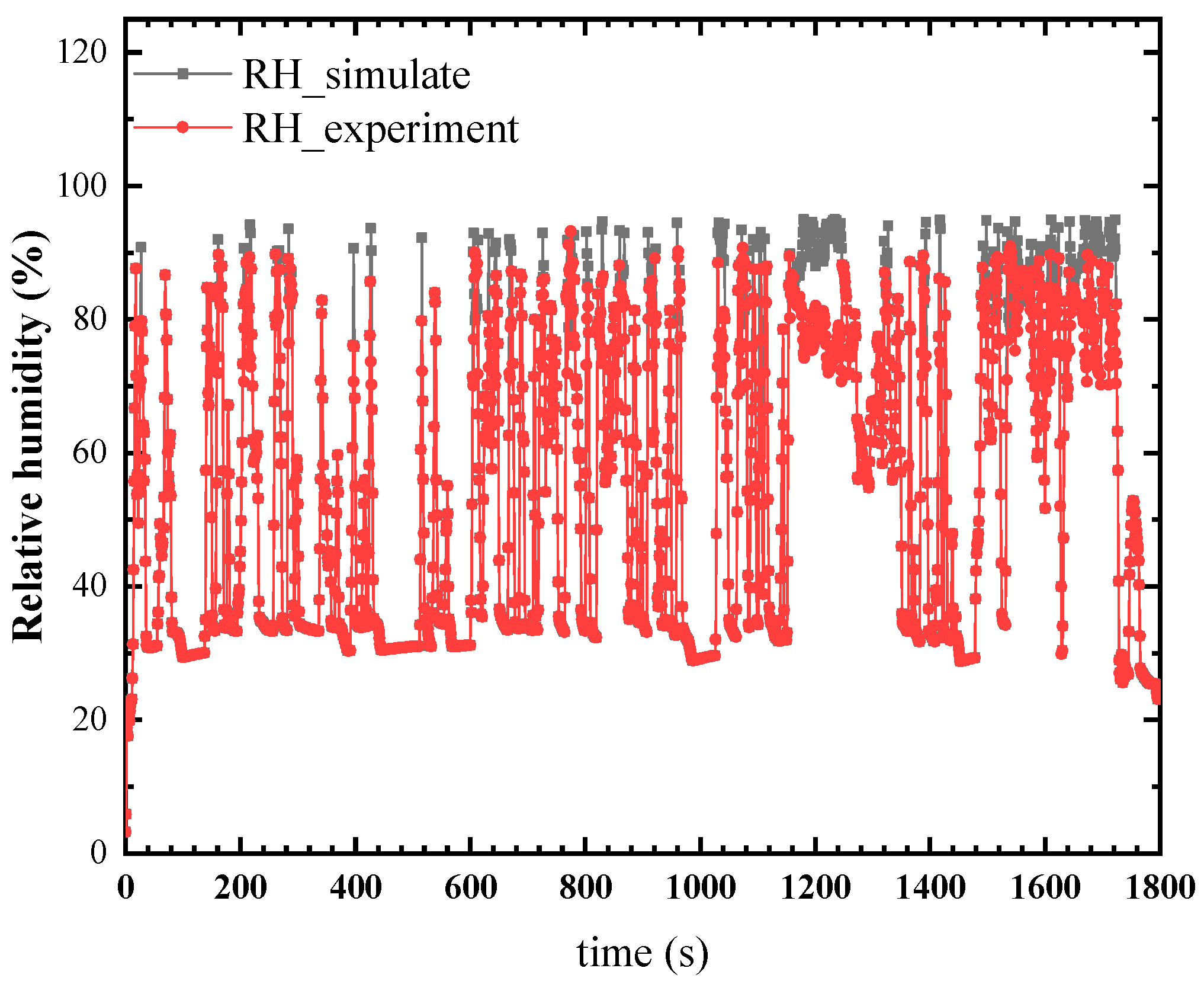
In previous research, temperature control has become the main method of thermal management. Considering that fuel cells are different from lithium batteries, the dual control of temperature and humidity will be more reasonable. This paper focuses on the water and thermal management system in a 30-kW proton exchange membrane fuel cell. Based on the functional model with a fuzzy controller, we take the humidification into consideration. Finally, a test bench for fuel cell stack testing was built with a corresponding air supply system, hydrogen supply system and cooling system. The simulation curve coincides with the test curve, and the temperature and humidity dual control proposed in this article can improve the output performance of the fuel cells.

2. Numerical Simulation

With the help from the software Amesim (Advanced Modeling Environment for performing Simulation of engineering systems), the functional model of the fuel cell system is built, which mainly includes stack, air supply, hydrogen supply, thermal management, circuit load and driver control. This paper focuses on the temperature and humidity control of the stack system. The following assumptions are made: (1) the reaction is carried out under steady-state conditions; (2) the gas is an ideal gas; and (3) the flow pattern in the plate channel is laminar.
Table 1 illustrates parameters in the simulation and experiment.

2.1. Fuel Cell Stacks

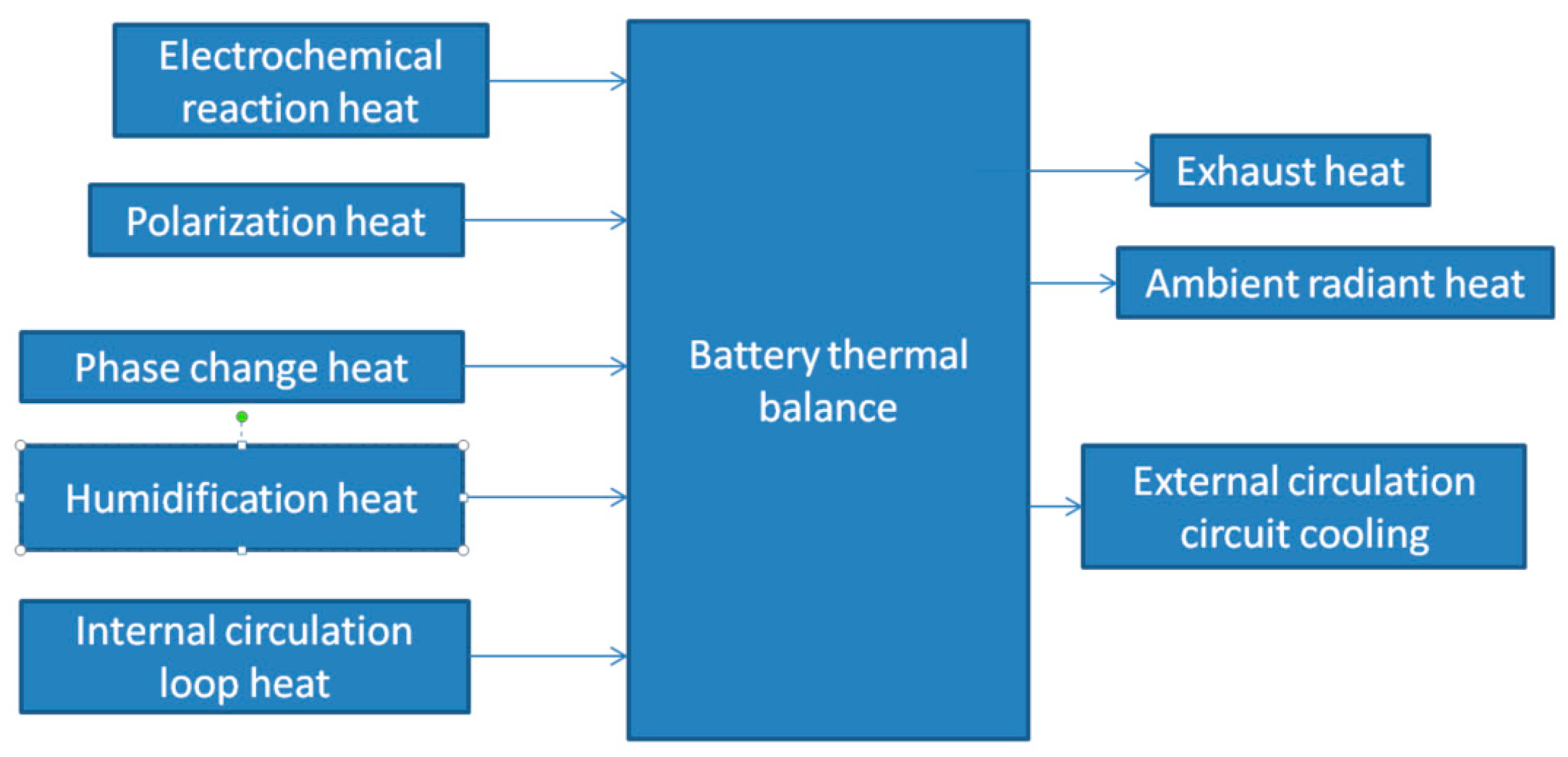
The main heat sources of the proton exchange membrane fuel cell system during the operation are as follows: the electrochemical heat is generated due to the irreversible running of the cell, the Joule heating is generated due to ohmic polarization, the heat introduced by the humidified gas and the external radiant heat. The two most important things are the reaction heat and Joule heat [16]. Thermal management is essential to the performance of the PEMFC system. Figure 2 shows the Schematic diagram of balance. A stack module is established in Amesim, which is used to simulate the reaction of PEMFC [17]. The temperature of the stack is calculated by the electrochemical loss and the heat exchange with the cooling device [18].

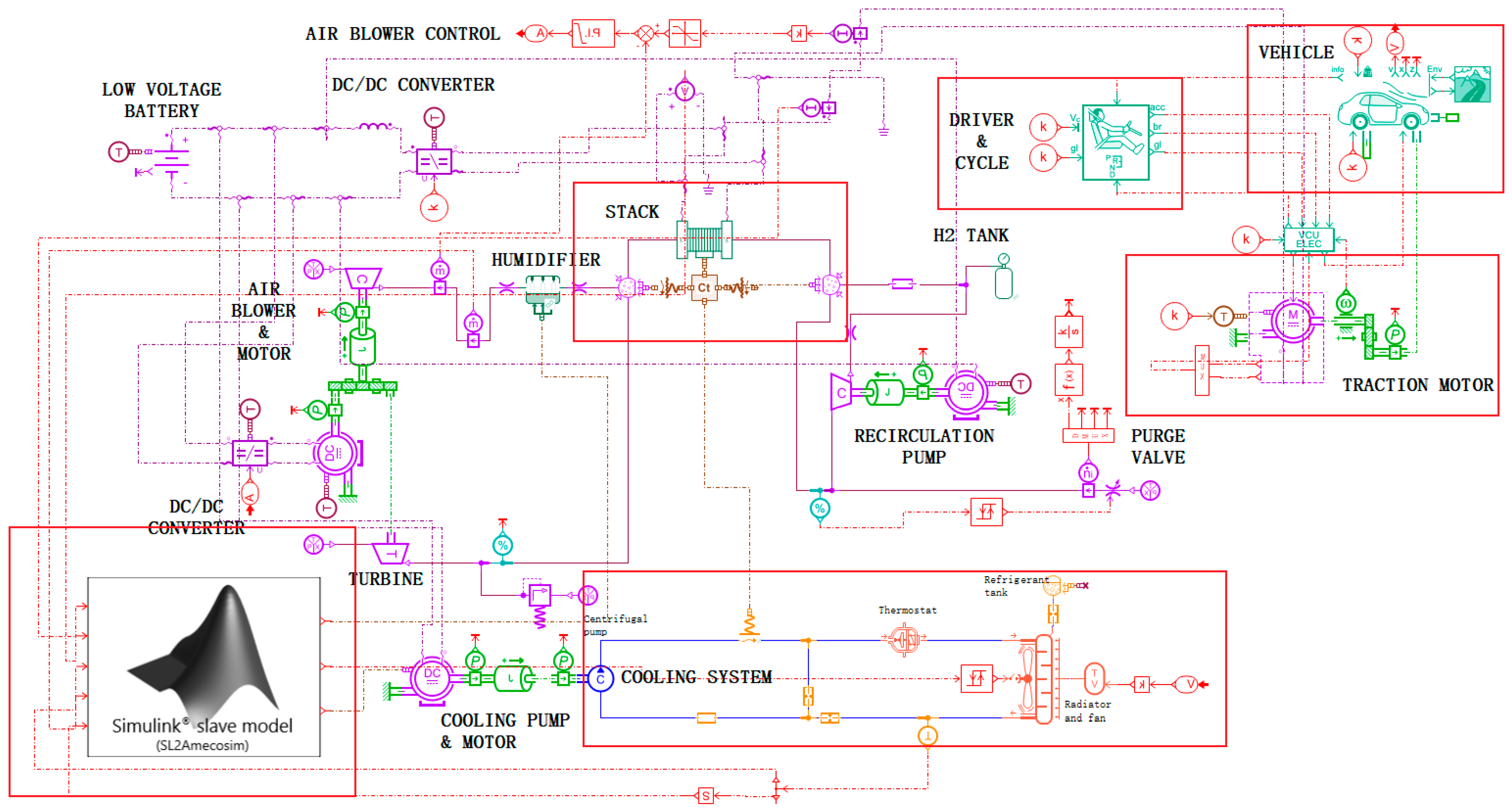
2.2. Fuel Cell Electric Vehicle (FCEV) System

Figure 3 shows the simulation diagram of the whole system from top to bottom and from left to right. There are many key parts in the system which include the driver module, vehicle module, transmission module, fuzzy control module, stack module, air and hydrogen module, as well as the cooling system. The following section will introduce the main output variable of these modules, as well as its roles in the whole system.
In order to satisfy the New European Driving Cycle (NEDC), which includes both urban and suburban and highway driving. The driver module is used to predict the driver acceleration and the braking command. The main output variables are gear lever position, brake control and acceleration control.
The total force (Ftot) is computed as:
Ftot = accel × masseq + Fstab
where:
  • masseq: equivalent mass (including inertias) [kg];
  • accel: necessary acceleration [m/s2];
  • Fstab: force for constant vehicle speed [N].
The driving power (Power) is computed as:
Power = Ftot × Vv
where:
  • Vv: actual vehicle velocity [m/s].
The vehicle module is used to evaluate the velocity and acceleration among all the operating car in this scenario. The velocity mainly depends on the electric machine torque, the resistive forces applied on the vehicle and the vehicle mass. The main output variables are vehicle speed, vehicle position and altitude. The aerodynamic drag (Faero) [N] is calculated as follows:
Faero = 0.5⋅ρair × S × Cx × (v + vwind)2
where:
  • ρair is the air density [kg/m3] at port 7;
  • Cx is the air penetration coefficient [null];
  • S is the vehicle active area [m2];
  • v is the vehicle linear velocity [m/s];
  • vwind is the input wind velocity [m/s] at port 7.
Without considering the fuel cell at this stage, the electrical network includes one battery and two DC/DC converters. The first DC/DC converter is integrated between the stack and the battery. The second DC/DC converter is integrated between the battery and the blower motor. It is used to control the torque of the motor to produce the correct blower speed and thus obtain the correct air mass flow to the cathode. The main output variables are current and potential.
The stack model evaluates the stack voltage, the temperature and the operating conditions at cathode and anode. It also predicts reactants and reaction products. In order to predict the dynamic thermal behavior, water transportation across the membrane, individual heat capacity of the stack, the heat generated by the fuel cell as well as the heat exchanged with the cooling system should all be considered. The main output variables include current, potential, temperature, enthalpy flow rate and mass flow rate. Hydrogen is provided by the high-pressure tank and its pressure regulator to the anode. A hydrogen mixture chamber is used to represent the anode gas volume and a pump is responsible for recirculate hydrogen from anode outlet to anode inlet. However, unreacted hydrogen will be recycled and be used again in the system. On the cathode, the air compressor is responsible for the air circulation, and the air will be humidified by the humidifier before it goes through the fuel cell stack. At the cathode outlet, a pressure relieve valve is introduced, and a turbine is also integrated in order to recover some power from the exhaust air.
The reaction rate (dn) [mol/s] is computed as follows:
dn = Istack × n × F × Ncell
  • Istack: stack current [A];
  • n: number of electrons involved in the reaction, here n = 2;
  • F: Faraday’s constant (96485.3415 [C/mol]);
  • Ncell: number of cells in the stack, here Ncell = 600.
The current density jstack [A/cm2] is computed as follows:
jstack = Istack/Scell
  • Istack: stack current [A]
  • Scell: active cell area [cm2]
A pump is used to generate the coolant (water) flow in the cooling loop in the cooling system. The coolant exchanges heat with the stack. When the coolant temperature rises, a thermostat opens, and a fan starts in order to exchange more heat with the radiator. The main output variables are heat flow rate (from cooling system to stack), the temperature of water and enthalpy flow rate and mass flow rate.
The mass flow rate is calculated so that the output pressure (high pressure) reaches the following value:
pout = pin + Δp
where pin is the input pressure (low pressure) and Δp is the pressure difference. The power provided by the pump (Pme) to the fluid is as follows:
Pme = Q × Δp × feff
0 ≤ feff ≤ 1
where Q is the volumetric flow rate, Δp the pressure difference and feff the global efficiency.
The projected area of the fan on the radiator acts as the ventilated surface of the radiator. Hence, the velocity of air through the ventilated surface (Vs) is given by:
Vs = Vair + Vfan
where Vair is the velocity of air at the radiator inlet [m/s], and Vfan is the additional velocity when the fan is operating [m/s]. The area of the ventilated surface AS is given by:
AS = π/4 × (Dext2 − Dint2)
where Dext is the external diameter of the fan [m], and Dint is the internal diameter of the fan [m]. The experimental heat exchanged on the ventilated surface HVexp is therefore:
HVexp = f(Vvs,qlh) × AS × Rh × Rl
where Rh is the radiator height [m], and Rl is the radiator length [m].
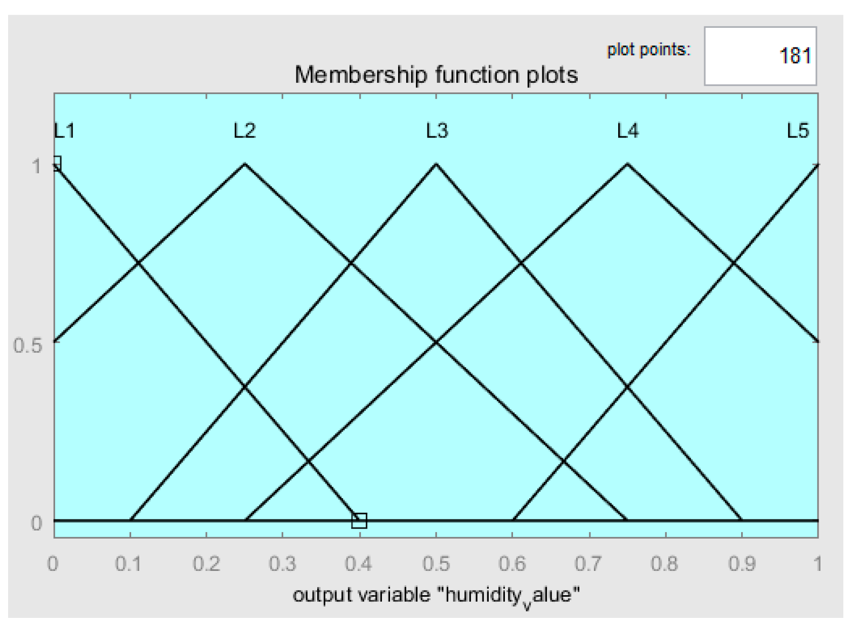
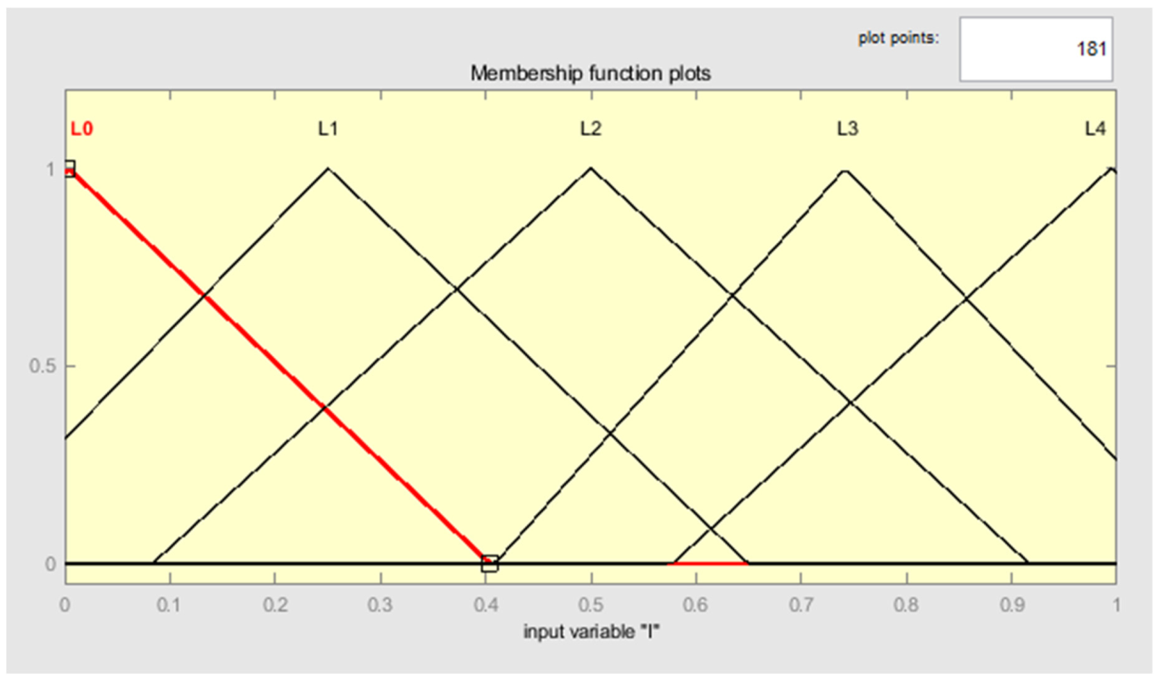
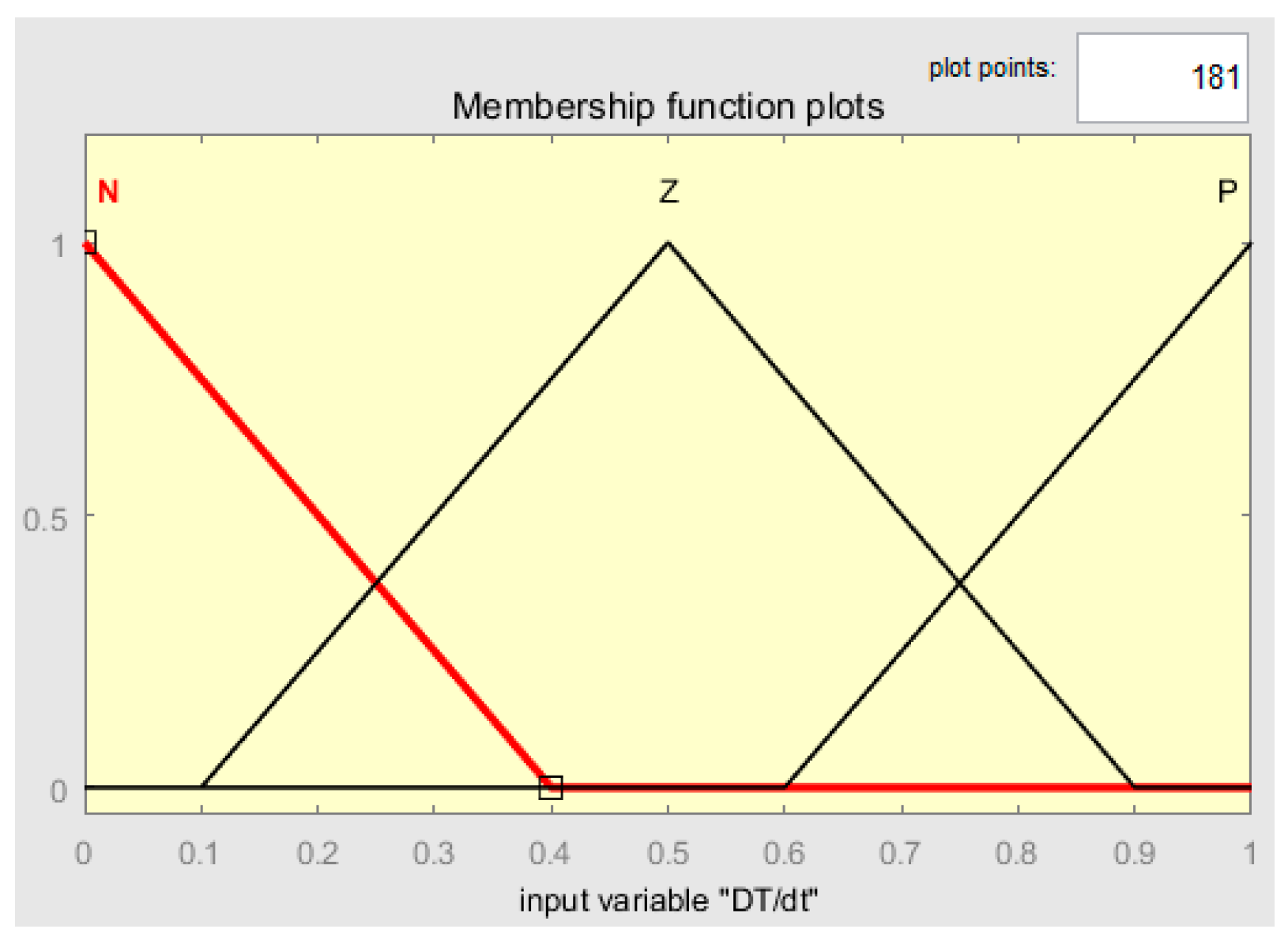
In this demo, a fuzzy controller is built to regulate the temperature and water content of the membrane. The entire simulation model is shown in 
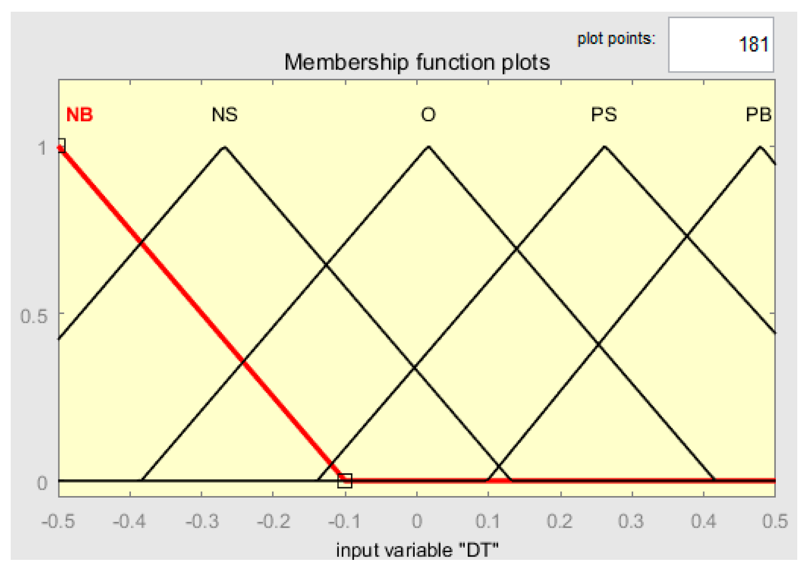
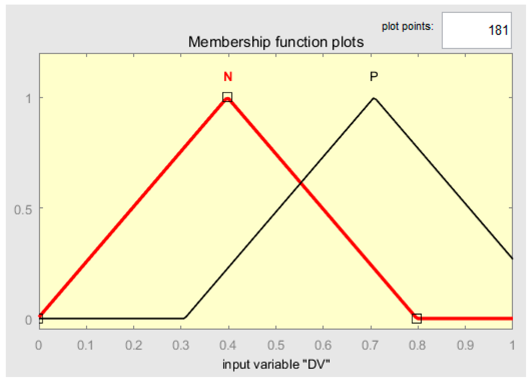
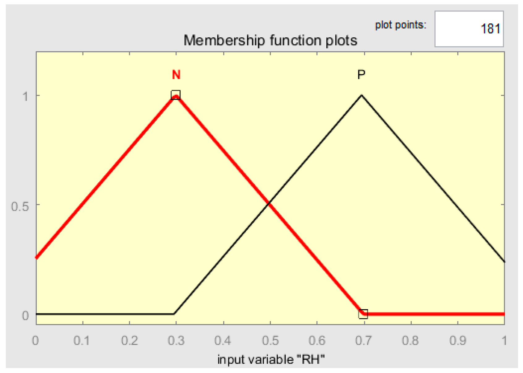
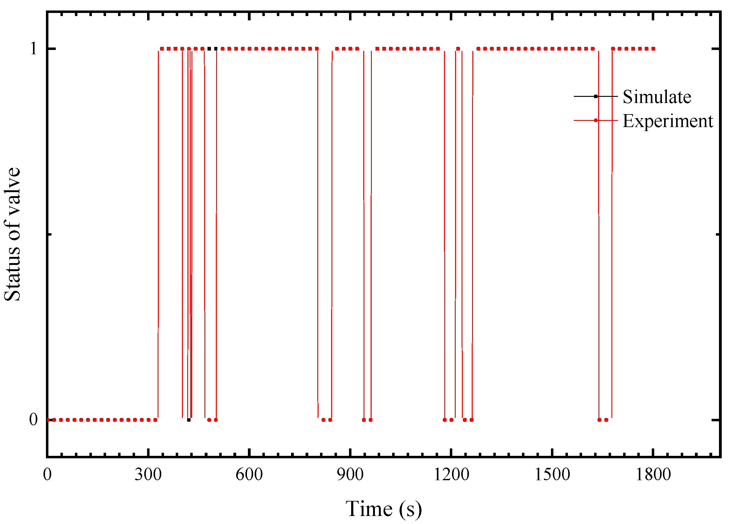
Figure 3. The fuzzy controller includes five inputs, namely, the current, the relative humidity of the hydrogen voltage change rate, the temperature error and its derivative. The three output objectives are the fan speed controller, which is used for regulating temperature, the solenoid valve on/off control of the bubble humidifier, which is used for humidity variation, and the speed of the pump. Figure 4, Figure 5, Figure 6, Figure 7 and Figure 8 show each input membership functions.
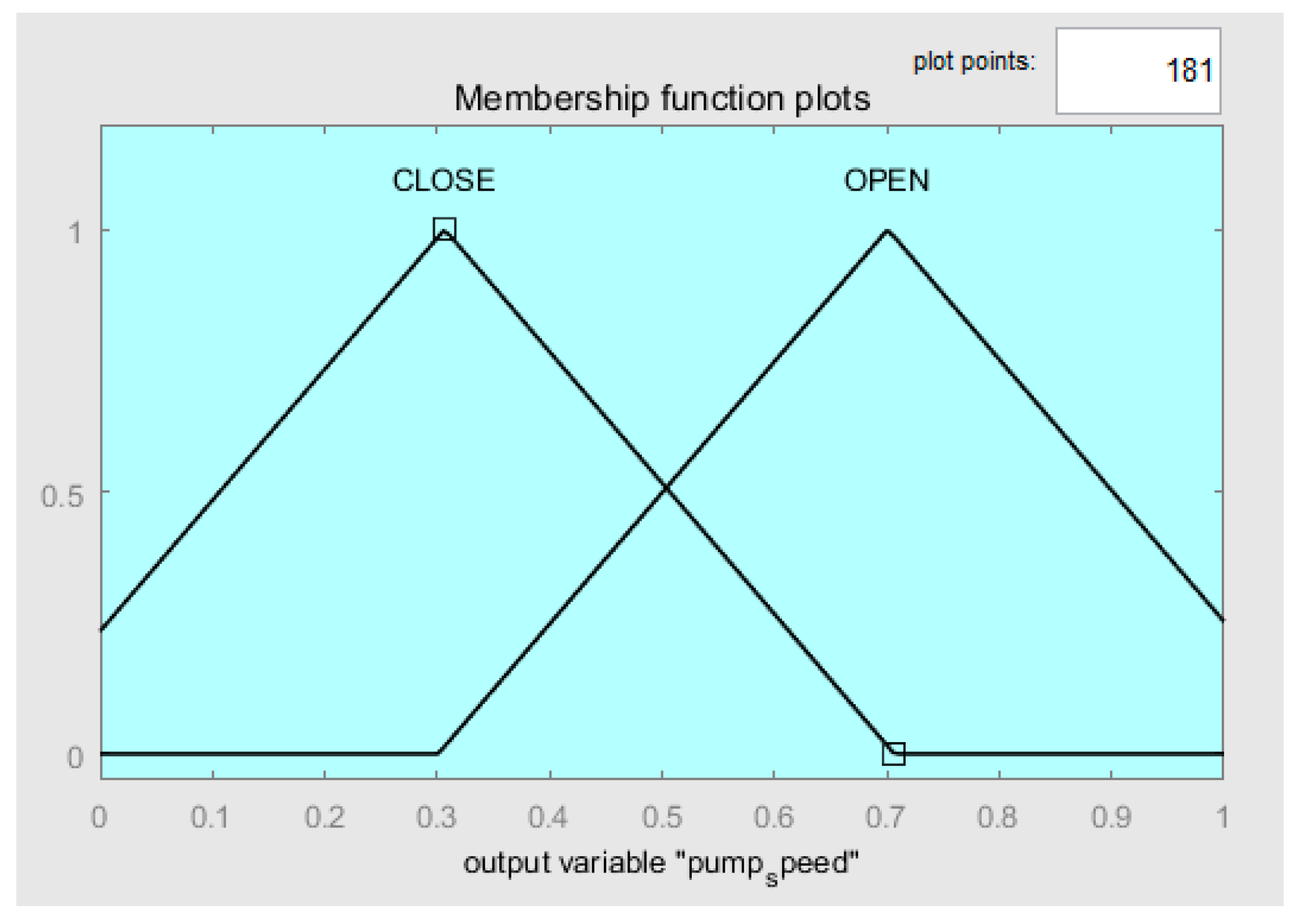
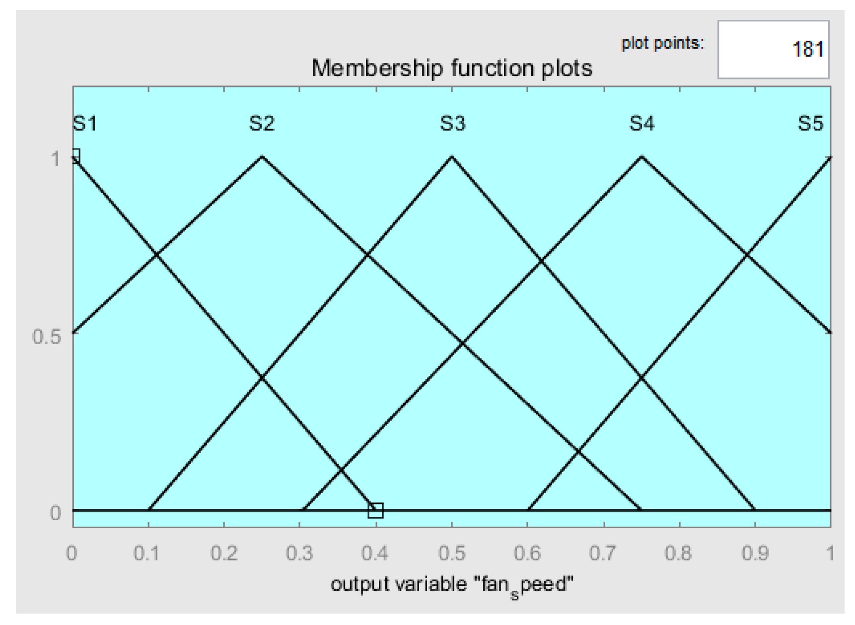
Figure 9, Figure 10 and Figure 11 are the membership functions of the output values. These functions are called defuzzification. The logic rules are in the form of IF-THEN statements [
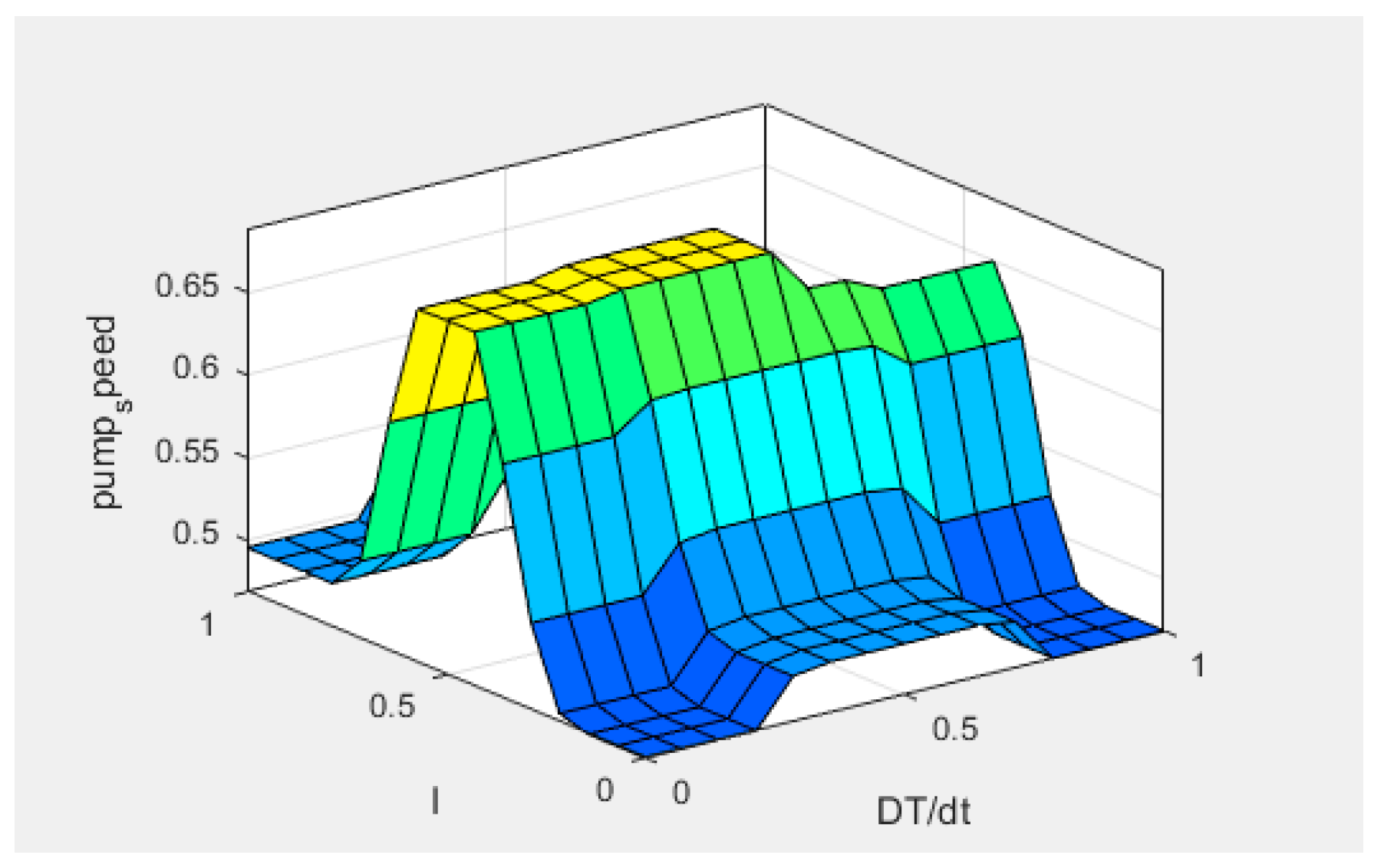
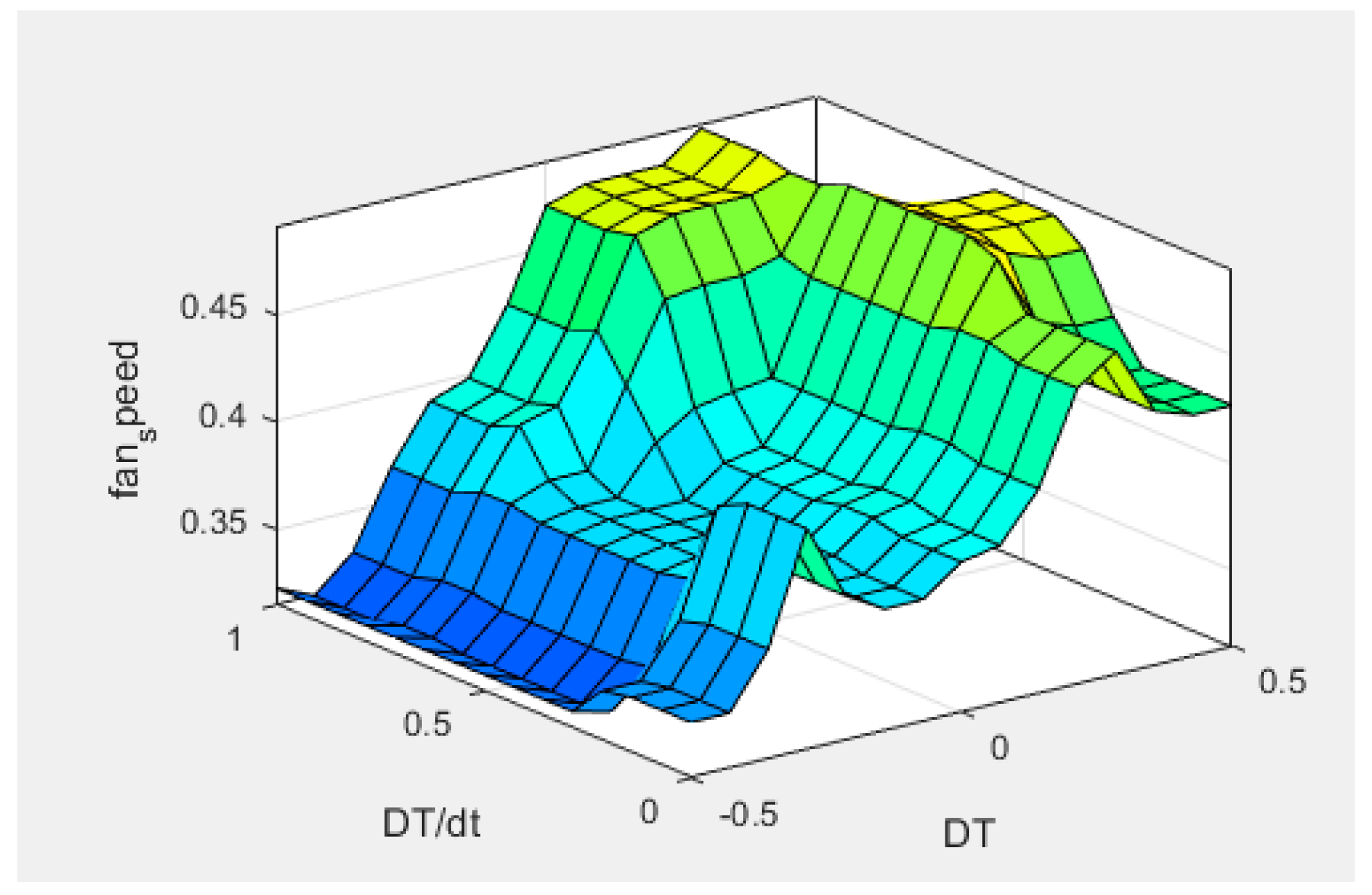
19]. The fuzzy logical control rules are demonstrated in the Figure 12, Figure 13 and Figure 14.

3. Experimental Setup and Conditions

Figure 15 shows the image of the experimental setup for the PEMFC STACK. The PEMFC system consists of a fuel cell stack (PANXING_TECH, 30 KW), a hydrogen cylinder (40 L, 99.99%pure), an air compressor (OTS, 1500–100 L), a coolant pump (Iwaki, RD-30), a mass flow meter (Daihor, DFG-8T) and a programmable electronic load (JT6385A, 800 V/500 A/50 kW). The mass power density of stack is 237 w/kg and the operating voltage is 250 V to 400 V. Deionized water is used as a coolant and take the heat out of the stack. The air supply and hydrogen are controlled by mass flow controllers, and air is humidified by passing through a bubbler humidifier. At the beginning of the experiment, the inlet temperature of hydrogen and oxygen were both 70 °C and the ambient temperature was 30 °C. The optimal temperature for PEMFC operation is generally in the range of 60 to 80 °C.
At the beginning of the experiment, first open the cooling loop, then open the air side loop; lastly, open the hydrogen side loop. In order to simulate the energy use of the car under the condition of NEDC, a pre-programmed adjustable load is used in this experience. The stack temperature, the valve of the opening and closing state and the relative humidity will be recorded throughout the whole process. At the end of the experiment, turn off the hydrogen, air and cooling system.

4. Results and Discussion

Under the operating conditions of the NEDC, Figure 16 shows that when the power of the fuel cell increases, the temperature of the fuel cell will rise correspondingly and vibrate slightly. The dot curve (using fuzzy controller) is closer to the dash curve (experiment), which shows no significant difference between the simulation and the experiment. The experimental results show that the fuzzy control can control the temperature better than the PID control, and the performance is improved by 5 °C.
The status signal of the valve is shown in Figure 17. The intake air is humidified when the valve is 1, and humidification stops when the valve is 0. The opening time of the valve accounts for 30% of the whole process. The working state of the valve does not switch frequently. Figure 18 shows an average cathode humidity of 60%, which is also assumed to be a suitable working condition. The humidity range is kept between 30% and 90%.
Under the operating conditions of NEDC, the result of the voltage (or power) comparison with the PID and fuzzy controller is shown in Figure 19. On the whole, the simulation results of the fuzzy control are consistent with the experimental results. In addition, the performance of the fuzzy control is better than that of the PID control, which is reflected in that the output voltage of the system using fuzzy control is higher. The dynamic data show that the fuel cell output voltage (power) increases by an average of approximately 5.8% with the fuzzy control.

5. Conclusions

The water and thermal management of model is built to analyze effect of temperature on cell performance. According to the heat generation and heat dissipation of fuel cell, the simulation model of the whole vehicle is developed. The model includes a driver, vehicle, transmission motor, air feeding, electrical network, stack, hydrogen supply and cooling system. In order to manage the water and heat of the stack, a fuzzy controller (five inputs and three outputs) is successfully designed, which shows that the fuzzy control has a good control effect on this time-delay and nonlinear system. The effect of humidity on the output performance of the fuel cell is considered in the fuzzy control. Brief summaries of the major results are listed below.
(1). Considering the mutual influence of the temperature and humidity, a model of a fuel cell vehicle system is established in this paper. Humidity is taken into account in the model. An experimental platform is built, and the experimental data are consistent with the simulation data.
(2). A fuzzy control algorithm with multi-inputs and multi-outputs is designed, and the effect is better than that of the PID control. The fuzzy control will be a better choice to deal with nonlinear systems with strong coupling and multiphase flow.

Author Contributions

Conceptualization, S.X. and Z.W.; methodology, S.X.; software, Z.W.; validation, Z.W., W.L. and T.Z.; formal analysis, Z.W., X.Z., Y.L. and S.Y.; investigation, Z.W..; resources, S.X..; data curation, Z.W.; writing—original draft preparation, Z.W..; writing—review and editing, S.X.; visualization, S.P., Z.H., J.Z., X.W., Q.S., H.H., D.L., Z.J.; supervision, S.X.; project administration, W.L.; funding acquisition, S.X. All authors have read and agreed to the published version of the manuscript.

Funding

This research has been financed by the National Key Research and Development Program for New Energy Vehicles in 2018, “Power System Platform and Vehicle Integration Technology for Extended-Range Fuel Cell Cars” (2018YFB0105400). It has also been funded by the Longquan Innovation Center of Zhejiang University. Thank you all.

Institutional Review Board Statement

Not applicable.

Informed Consent Statement

Not applicable.

Data Availability Statement

All the underlying data related to this article are available from the first author upon request.

Conflicts of Interest

The authors declare no conflict of interest.

References

  1. Liu, Z.; Shi, T.; Hao, H.; Zhao, F. Research on the development of fuel cell vehicles in China. Automot. Technol. 2018, 1, 1–9. [Google Scholar]
  2. China Automotive Technology and Research Center. 2014 Energy Saving and New Energy Vehicle Yearbook; China Economic Publishing House: Beijing, China, 2014. [Google Scholar]
  3. Wang, Y.; Mou, L.; Liu, S. Analysis of water and heat management systems of typical foreign fuel cell vehicles. Intern. Combust. Engine Accessories 2019, 24, 198–200. [Google Scholar]
  4. Li, J.; Wang, Y.; Tao, Q.; Su, C. Design, modeling and analysis of heat dissipation system for full-power fuel cell vehicles. J. Automot. Eng. 2019, 9, 462–467. [Google Scholar]
  5. Yan, W.-M.; Zeng, M.-S.; Yang, T.-F.; Chen, C.-Y.; Amani, M.; Amani, P. Performance improvement of air-breathing proton exchange membrane fuel cell stacks by thermal management. Int. J. Hydrogen Energy 2019, 9, 60–68. [Google Scholar] [CrossRef]
  6. Yuan, Y. Research on Fuel Cell Thermal Management System and Key Components. Master’s Thesis, Xiangtan University, Xiangtan, China, 2019. [Google Scholar]
  7. Zhang, B.; Liu, J.; Li, J.; Xie, S. Progress of fuel cell cooling methods and thermal management control strategies. Battery 2019, 49, 158–162. [Google Scholar]
  8. Zhang, K. Design and Simulation of Heat Dissipation Structure of Lithium-Ion Power Battery for Pure Electric Vehicles. Master’s Thesis, Chang’an University, Xi’an, China, 2019. [Google Scholar]
  9. Jang, J.; Chiu, H.; Yan, W.; Sun, W. Effects of operating conditions on the performances of individual cell and stack of PEM fuel cell. J. Power Sources 2008, 180, 476–483. [Google Scholar] [CrossRef]
  10. Lobato, J.; Cañizares, P.; Rodrigo, M.A.; Linares, J.J. PBI-based polymer electrolyte membranes fuel cells. Electrochim. Acta 2007, 52, 3910–3920. [Google Scholar] [CrossRef]
  11. Harms, C.; Kohrmann, F.; Dyck, A. Study of the influence of key test parameters on the performance of a PEMFC stack. Solid State Ion. 2015, 275, 75–76. [Google Scholar] [CrossRef]
  12. Rodatz, P.; Büchi, F.; Onder, C.; Guzzella, L. Operational aspects of a large PEFC stack under practical conditions. J. Power Sources 2004, 128, 208–217. [Google Scholar] [CrossRef]
  13. Seo, S.-H.; Oh, S.-D.; Oh, H.; Kim, M.; Lee, W.-Y.; Kwak, H.-Y. Thermal management for a hydrogen-fueled 1-kW PEMFC based on thermoeconomic analysis. Int. J. Hydrogen Energy 2019, 44, 24934–24946. [Google Scholar] [CrossRef]
  14. Raman, S.; Swaminathan, S.; Bhardwaj, S.; Tanneru, H.K.; Bullecks, B.; Rengaswamy, R. Rapid humidity regulation by mixing of dry and humid gases with feedback control for PEM fuel cells. Int. J. Hydrogen Energy 2019, 44, 389–407. [Google Scholar] [CrossRef]
  15. Strahl, S.; Costa-Castelló, R. Temperature control of open-cathode PEM fuel cells. IFAC Pap. 2017, 50, 11088–11093. [Google Scholar] [CrossRef] [Green Version]
  16. Ghasemi, M.; Ramiar, A.; Ranjbar, A.; Rahgoshay, S. A numerical study on thermal analysis and cooling flow fields effect on PEMFC performance. Int. J. Hydrogen Energy 2017, 42, 24319–24337. [Google Scholar] [CrossRef]
  17. Pu, J.; Qin, X.; Lu, Y.; Wang, Y.; Ding, T.; Zhao, Z. Design and Research of Fuel Cell Thermal Management System. Automot. Dig. 2019, 4, 24–27. [Google Scholar]
  18. Xie, Y.; Zou, J.; Peng, C. Temperature control of proton exchange membrane fuel cell based on variable incremental fuzzy theory. Control Theory Appl. 2019, 36, 428–435. [Google Scholar]
  19. Choi, E.J.; Park, J.Y.; Kim, M.S. Two-phase cooling using HFE-7100 for polymer electrolyte membrane fuel cell application. Appl. Therm. Eng. 2019, 148, 868–877. [Google Scholar] [CrossRef]
Figure 1. Physical PEMFC.
Sustainability 13 10578 g001
Figure 2. Schematic diagram of fuel cell thermal balance.
Sustainability 13 10578 g002
Figure 3. FCEV system.
Sustainability 13 10578 g003
Figure 4. The membership functions of temperature error, which are divided into five levels.
Sustainability 13 10578 g004
Figure 5. The membership functions of current, which are divided into five levels.
Sustainability 13 10578 g005
Figure 6. The membership functions of the derivate of temperature error, which are divided into three levels.
Sustainability 13 10578 g006
Figure 7. The membership functions of the derivate of voltage, which are divided into two levels.
Sustainability 13 10578 g007
Figure 8. The membership functions of relative humidity, which are divided into two levels.
Sustainability 13 10578 g008
Figure 9. The membership functions of the humidity valve, which are divided into two levels.
Sustainability 13 10578 g009
Figure 10. The membership functions of pump speed, which are divided into two levels.
Sustainability 13 10578 g010
Figure 11. The membership functions of fan speed, which are divided into five levels.
Sustainability 13 10578 g011
Figure 12. Fuzzy rules of controlling the pump speed using bar graph.
Sustainability 13 10578 g012
Figure 13. Fuzzy rules of controlling the humidity valves using bar graph.
Sustainability 13 10578 g013
Figure 14. Fuzzy rules of controlling the fan speed using bar graph.
Sustainability 13 10578 g014
Figure 15. Fuel cell test bench.
Sustainability 13 10578 g015
Figure 16. Temperature change under NEDC operating conditions.
Sustainability 13 10578 g016
Figure 17. Signal for the valves.
Sustainability 13 10578 g017
Figure 18. Relative humidity.
Sustainability 13 10578 g018
Figure 19. Comparison of the fuel cell power.
Sustainability 13 10578 g019
Table 1. Physical properties and constants.
ParameterValueUnit
Specific heat capacity of the fuel cell stack1260Jkg−1 K−1
Fuel cell stack mass135kg
Air density1.184Kg m−3
Specific heat capacity of air1012Jkg−1 K−1
Optimal reachable liquid water saturation0.165-
Theoretical potential1.23V
Charge transfer coefficient0.3-
Geometric catalyst surface area5 × 10−2m2
Ohmic stack resistance0.3Ω
Partial pressure of oxygen at the cathode0.21PairPa
Liquid water density970Kg m−3
Liquid water surface tension0.0625N m−1
Liquid water viscosity3.52 × 10−4Pa s
Cathode ambient pressure0.1MPa
Cathode ambient temperature298.35k
Cathode ambient vapor pressure2400Pa
Activation energy of evaporation0.45V
Catalyst layer thickness1 × 10−5m
Catalyst layer volume9 × 10−7m3
Effective thickness of diffusion media5 × 10−4m
Publisher’s Note: MDPI stays neutral with regard to jurisdictional claims in published maps and institutional affiliations.

