Article

Many-Objective Hybrid Optimization Method for Impeller Profile Design of Low Specific Speed Centrifugal Pump in District Energy Systems

1
State Key Laboratory of Fluid Power and Mechatronic Systems, Zhejiang University, Hangzhou 310027, China
2
School of Mechanical Engineering, Zhejiang University, Hangzhou 310027, China
3
Zhejiang Fuchunjiang Hydropower Equipment Co., Ltd., Hangzhou 311504, China
*
Author to whom correspondence should be addressed.
Sustainability 2021, 13(19), 10537; https://doi.org/10.3390/su131910537
Submission received: 24 July 2021 / Revised: 4 September 2021 / Accepted: 16 September 2021 / Published: 23 September 2021
(This article belongs to the Special Issue District Energy System and Energy Management)

Abstract

:
Low specific speed centrifugal pumps (LSSCP) are widely utilized in district energy systems to promote the integration of renewable energy. However, the performance of LSSCP becomes inefficient due to harsh operating conditions resulting in substantial increase in energy consumption. Many-objective optimization is significant in improving the performance of LSSCP and promoting the sustainability of district energy systems. Among the existing optimization methods, global optimization methods are limited by high computational cost when solving many-objective optimization problems, and gradient-based optimization methods face difficulties in locating the global optimum. In the present study, a hybrid optimization method was developed for solving many-objective optimization problems of LSSCP. The LSSCP optimization result of the hybrid algorithm was compared with that of the non-dominated sorting genetic algorithm (NSGA), so as to demonstrate the capacity of the proposed method. In the designed flow condition without cavitation, the hydraulic efficiency obtained by the hybrid optimization algorithm was found to be 9.5%, 5.4%, and 4.7% higher than those of the original, NSGA-II, and NSGA-III optimized results, respectively. The shaft power was 10.3%, 8.7% and 5.1% less than said three optimized results. The maximum turbulent kinetic energy in the flow passage obtained from the hybrid optimization was only 2.2 J/kg, which was 67% and 46% less than that of the NSGA-II and NSGA-III optimized results, respectively. In the designed flow condition with cavitation, the net positive suction head critical optimized by the hybrid model was 0.857 m, which was substantially reduced compared with the original and NSGA- II optimized results.

1. Introduction

District energy system is a sustainable strategy for integrating and balancing variable renewable energy sources. It integrates district heating and cooling with combined heat and power, thermal storage, and heat pumps in collaboration to achieve systematic resource conservation and sustainable development [1]. Centrifugal pumps are employed as core components in district energy systems to circulate fluids [2]. It facilitates the integration of renewable energy, minimizes heat losses, and reduces gas costs. The centrifugal pumps employed in district energy systems are characterized with low specific speed. The range of flow rate and head are 25–120 m3/h and 46~576 m, respectively. The impeller outlet diameter of low specific speed centrifugal pump (LSSCP) is large with significant disk friction loss [3,4]. In addition, if cavitation occurs, vapor will diffuse rapidly to fill in the extremely narrow impeller passage, resulting in a reduction in the suction capacity of LSSCP and a generation of more energy consumption than required [5]. Up to 30% of the energy and cost consumed by centrifugal pumps can be saved by optimizing their performance [6]. Hence, it is of great significance to optimize the efficiency and suction capacity of LSSCP for energy saving and promoting sustainability of district energy systems. Among all components in LSSCP, the impeller has the greatest impact on the performance of LSSCP since the energy is generated through it [7,8]. Therefore, the key to optimize the performance of LSSCP is the impeller profile.
With advancement of modern computational power, efficient design methods coupling the optimization algorithms with computational fluid dynamics (CFD) have been applied in the turbomachinery. The global optimization method is adopted to get an expansive scope of possible solutions and discover the optimal individual. It is preferred in the design of pumps in previous research because of its advantage in reaching the global optimum. Table 1 summarizes the global optimization method used for the performance optimization of pumps commonly in recent years, including multi-objective genetic algorithm (MOGA) [9,10,11], artificial bee colony (ABC) [7], eagle strategy (ES) [12], artificial fish swarm algorithm (AFSA) [13], and non-dominated sorting genetic algorithm-II (NSGA-II) [14,15,16,17]. Pei et al. used the particle swarm optimization algorithm to arrange the optimal solution of the impeller parameters and efficiency of LSSCP, and performance of LSSCP was improved after optimization [3]. Wang et al. adopted NSGA-II to optimize efficiency and net positive suction head of LSSCP, which caused secondary flow and other unexpected flow structures have diminished or vanished in the optimized pump [5].
As can be seen in Table 1, a problem that existed in the past research is that major parameters affecting the performance of LSSCP, namely head, efficiency, shaft power, and suction capability, have not been fully considered as the optimization objectives. This is due to the shortcomings of the global optimization algorithm, such as encoding complexity and long iterations. Although NSGA-II has low encoding complexity and is widely used in the field of turbomachinery, it is not suitable for many-objective optimization of LSSCP with high dimensional space due to its crowding distance mechanism [18]. Moreover, although Pareto optimality can be obtained, the local optimality cannot be achieved due to the contradiction of the various optimization objectives. The gradient-based optimization method is a search optimization algorithm, which takes the gradient of the objective function with respect to the design variables (DVs) as the optimization direction. The global optimization method and the gradient-based method were applied to turbine design, and shown that the gradient-based method calculated the Pareto front at a remarkably lower computational cost [19]. Unfortunately, the gradient-based optimization method is effective for the single objective function, but has limitations for obtaining the global optimal solution of multiple optimization objectives [20].
LSSCP are sized to meet maximum flow rate required by district energy system. As the demand of the system frequently varies, throttling devices such as valves are installed to control the flow rate and adjust pump output. The problem of such device is the sacrifice of energy efficiency. An energy-saving approach is to install a motor inverter that regulates the rotational speed and controls the flow rate in the supply network. Wang et al. proposed a new hydraulic regulation method to realize the on-site hydraulic balance of district heating systems with centrifugal pump controlled by frequency inverter. The application of their method reduces electricity consumption by at least 26.6% compared to conventional circulation pump configurations [21]. Kuosa et al. propose a new district heating system concept based on the control of mass flow by a pump with inverter, which will replace the traditional district heating network and control valves for throttling the water flow [22]. However, as the head of LSSCP is proportional to the square of the rotational speed, the reduction in pump speed can often cause a significant head drop which also effects operating performance. Hence, the proposed many-objective optimization method that fully considers head, efficiency, shaft power, and cavitation can be employed to improve LSSCP performance under variable flow rate.
The hybrid optimization algorithm, which combines the global optimization algorithm and the gradient-based optimization method, can quickly and accurately converge to the global optimal solution of multiple optimization objectives. The application of this algorithm ensures the design accuracy and greatly reduces the design cycle of LSSCP. The consequence indicates that the optimization approach proposed in this paper is satisfactory for the design of LSSCP and can be flexibly expand into design of other turbomachinery.

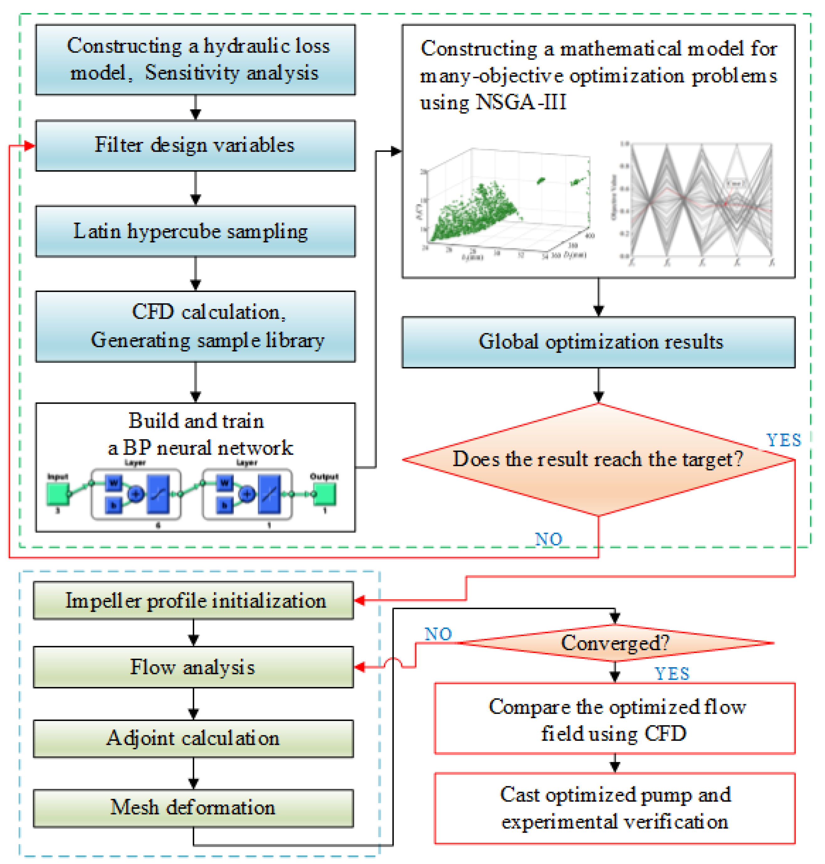
2. Model Description

A hybrid optimization method is presented to improve the impeller profile of LSSCP as shown in Figure 1. In the first, sensitivity analysis, Latin hypercube sampling (LHS), CFD calculation, back propagation neural network (BPNN) fitting, and multi-objective global optimization by non-dominated sorting genetic algorithm-III (NSGA-III) are carried out on a limited number of DVs to obtain the solution of the global optimum. Then the output of the global optimization is adopted as the initial state of the adjoint method optimization. The overall impeller profile is improved by applying the adjoint method to achieve the performance optimization. The hybrid algorithm can quickly and accurately converge to the global optimal solution of many-objective optimization, which is greatly reducing the design cycle and ensuring design accuracy of LSSCP.

2.1. Sensitivity Analysis

The impeller geometry is very complex, which is described by a large number of profile parameters. There are many DVs during optimization, which will increase the computational load. Thus, it is necessary to conduct sensitivity analysis to screen out suitable DVs from many profile parameters of the impeller in the global optimization. In past research, the outlet diameter D2, the outlet width b2, the inlet angle β1, the outlet angle β2, the number of blades Z, and the inlet diameter D1 were the main profile parameters that determine the shape of the impeller. They were also the major DVs selected in most studies, as shown in Table 1. We analyzed the sensitivity of the above main profile parameters by using the hydraulic loss model [23].
The hydraulic loss of the LSSCP mainly comes from the following eight items, including suction hydraulic loss (Δhs), impeller inlet hydraulic loss (Δhin), impeller flow passage friction loss (Δhf), impeller diffusion shrinkage loss (Δhd), inlet fluid flow direction hydraulic loss (Δhi), impeller outlet hydraulic loss (Δhout), the volute friction loss (Δhv), and the diffusion loss in the volute (Δhdv). Each profile parameter has different effects on the calculation results of the hydraulic loss model. By calculating these eight losses, head H, shaft power P, and hydraulic efficiency ηh based on the hydraulic loss model can be obtained. Equations (1)–(5) reflect the relationship between them.
  ( Δ h s , Δ h i n , Δ h f , Δ h d , Δ h i , Δ h o u t , Δ h v , Δ h d y ) = f ( D 2 , b 2 , β 1 , β 2 , D 1 , Z )
H T = Γ ( D 2 , b 2 , Q , β 2 )
  H = H T Δ h s Δ h in Δ h f Δ h d Δ h i Δ h out Δ h v Δ h dy
  η h = H H T
  P = ρ g Q H η
where HT, Q, ρ, g, and η are the theoretical head, the flow rate, the density, the acceleration of gravity, and the efficiency, respectively. The process of calculating the sensitivity of H, ηh, and P is shown in Equation (6).
{   S H = | H ( X + 2 % X ) H ( X ) H ( X ) | / 2 % S η h = | η h ( X + 2 % X ) η h ( X ) η h ( X ) | / 2 % S P = | P ( X + 2 % X ) P ( X ) P ( X ) | / 2 % X = D 1   o r   D 2   o r   β 1   o r   β 2   o r   b 2   o r   Z
where SH, Sηh, and SP are the sensitivity value of each profile parameter to H, ηh, and P, respectively.

2.2. Latin Hypercube Sampling

Latin Hypercube Sampling (LHS) is a method of stratified random sampling from the distribution interval of DVs, which can ensure the uniformity of the distribution of DVs within the range of DVs. In the global optimization, LHS was carried out to generate 60 sets of DVs samples. Based on the sample value of DVs, CFturbo and Workbench 19.0 were used for parametric design and automatic co-simulation.

2.3. Surrogate Model

BPNN has capability in arbitrary complex pattern classification and multi-dimensional function mapping [24]. Hence, we applied BPNN to establish the approximate functional relationship between the DVs and the optimization objectives to reduce the computational cost. For ensuring the fitting accuracy of BPNN, the mean square error between the fitting value and CFD calculation value should be less than 0.5, and networks that do not meet above requirements need to be retrained. From the 60 samples, 40 groups were randomly selected as the training set of the BPNN, and the remaining 20 groups were used as the test set. The establishment process of BPNN is relatively simple, so it will not be described here.

2.4. The Global Optimization Using NSGA-III

NSGA-II is the most widely used in multi-objective optimization problems for the centrifugal pump [5,8,14,15,16,17]. When NSGA-II is utilized to solve the optimization problems of four or more objectives, which is named many-objective optimization problem, the diversity of the population is reduced due to the lack of elite selection mechanism. This feature considerably slows down the search process. The difficulty is resolved by NSGA-III, which is proposed based on NSGA-II by Deb and Jain [18]. The remarkable progress of NSGA-III is the development of the reference-point based selection mechanism, which replaces the crowding distance through the following steps. It improves the diversity and distribution of Pareto solutions by using this method [18]. Thus, compared with NSGA-II, it is better to use NSGA-III to optimize the performance of LSSCP.
Step1: Divide the population into nondominated levels.
Step2: Determine the reference points on a hyperplane.
Step3: Adaptive normalization of population members.
Step4: Associate each population member with a reference point.
Step5: Count the number of population members (niche number) and associate them with each reference point.
Step6: The reference point with the smallest niche number is selected, and the population members which are closest to the reference point are added to the next generation. The niche number at this reference point is increased by one.
Step7: Repeat Step 5 until the population members in the next generation reach the maximum number of iterations.

2.5. The Gradient-Based Optimization Using Adjoint Method

If only the NAGA-III is used for optimization, due to the complexity of the LSSCP impeller DVs, it will still consume expensive iteration costs. Moreover, although Pareto optimality can be obtained by applying NSGA-III, local optimality cannot be achieved due to the contradiction between the high dimensional optimization objectives. Different from the conventional gradient-based methods, the adjoint method based on adjoint theory is the most successful and efficient approach for solving large-scale complex design problems [25]. The advantage of the adjoint method is that the gradient of the objective function relative to the DVs is eliminated through the well-advised selection of the adjoint variables [26,27]. Thus, the output of the NAGA-III optimization is adopted as the initial state of the adjoint method optimization. The adjoint method is used to improve the overall impeller profile to achieve performance optimization.
According to the principle of adjoint method, the adjoint equation of fluid applied to CFD is derived. In the Cartesian coordinate system, the governing equation of fluid is:
  U t + Φ x + Ω y + Λ z = 0
where
  U = [ p u v w ] ,   Φ = [ u u 2 + p ρ u v u w ] ,   Ω = [ v u v v 2 + p ρ v w ] ,   Λ = [ w u w v w w 2 + p ρ ]
u, v, and w are the velocity components in the Cartesian coordinate system, respectively. p is the pressure. The variation of the governing equation is:
δ Φ x + δ Ω y + δ Λ z = 0
where
δ Φ = Φ W δ W + Φ x δ x + Φ y δ y + Φ z δ z = Φ W δ W + Φ x j   δ x j
δ Ω = Ω W δ W + Ω x δ x + Ω y δ y + Ω z δ z = Ω W δ W + Ω x j   δ x j
δ Λ = Λ W δ W + Λ x δ x + Λ y δ y + Λ z δ z = Λ W δ W + Λ x j   δ x j
Integrate the left-hand side of Equation (9) and multiply it by the Lagrange factor Ψ :
D Ψ ( δ Φ x + δ Ω y + δ Λ z ) d V = D [ ( Ψ δ Φ ) x + ( Ψ δ Ω ) y + ( Ψ δ Λ ) z ] d V D [ Ψ x δ Φ + Ψ y δ Ω + Ψ z δ Λ ] d V = 0
Add Equation (13) to the variation of the original objective function:
δ I 0 = δ I + D [ ( Ψ δ Φ ) x + ( Ψ δ Ω ) y + ( Ψ δ Λ ) z ] d V D [ Ψ x δ Φ + Ψ y δ Ω + Ψ z δ Λ ] d V = I W   δ W + I x δ x + I y δ y + I z δ z + D [ ( Ψ δ Φ ) x + ( Ψ δ Ω ) y + ( Ψ δ Λ ) z ] d V D [ Ψ x δ Φ + Ψ y δ Ω + Ψ z δ Λ ] d V
The δ W term in Equation (14) is extracted and its coefficient is set to 0. Thus, the variation of the objective function is unrelated to the variation of the DVs. The adjoint equation of the N−S equation can be obtained in the flow calculation domain as:
( Φ W ) T   Φ x + ( Ω W ) T   Ω y + ( Λ W ) T   Λ z = 0
The boundary conditions accompanying Equation (15) can be obtained by extracting the δ W term on the boundary of the calculation domain and setting it to 0.
Using the adjoint solver of ANSYS Fluent for the hybrid optimization. Firstly, use the profile of the impeller obtained from the optimization using NSGA-III as the initial state to calculate the flow field. Then, based on the calculation result of the flow field, the gradient δ I δ x i of the objective function to the profile of the impeller is calculated using the adjoint method. Drive the mesh deformation of the fluid domain and update the profile of the impeller. Finally, recalculate the flow field after the mesh is deformed, and repeat steps (2) and (3) until the residual of the optimization objective function converges.

3. Numerical Methods and Test Equipment

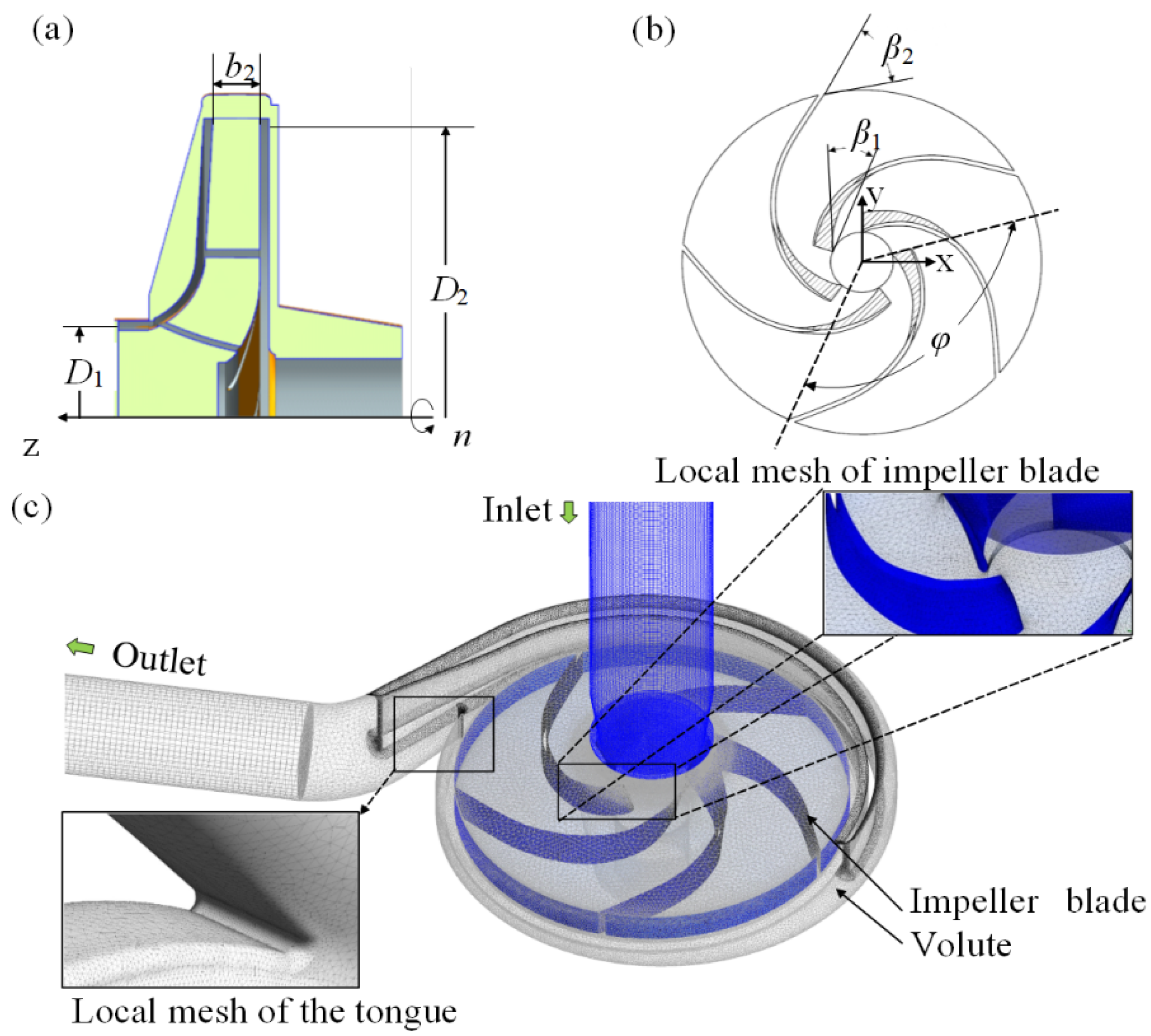
3.1. Numerical Methods

The original structure of optimization design is an LSSCP with a single-stage cantilever structure. The impeller of LSSCP has 5 blades and the designed rotational speed is 1450 rpm. Major performance parameters include the designed flow rate Qd = 100m3/h, head Hd = 50 m, and the specific speed NS = 46.9. The designed NPSHr is 3 m. Figure 2a,b and Table 2 show the geometry of LSSCP and the main profile parameters of the impeller, respectively.
The fluid domain mesh is shown in Figure 2c. A non-simplified model considering the clearance flow field between the volute and the impeller was adopted as the computational domain to improving the calculation accuracy. Unstructured tetrahedral mesh was used in the impeller and volute. An O-type mesh was applied in the inlet and outlet pipes of the volute. A mesh sensitivity analysis based on H was carried out to achieve an adequate mesh resolution, and the number of nodes was 4.94 million.
The shear stress transport (SST) k-ω model is selected as the turbulence model, which been employed to precisely capture flow separation under inverse pressure gradient by introducing the eddy viscosities term. The accuracy of SST k-ω model in calculating the flow field of turbomachinery has been validated in previous research [28,29]. Boundaries of the volute and the impeller computational domain were set as static boundary condition and rotating boundary condition, respectively. Mixture model and Zwart-Gerber-Belamri model were applied as the multiphase flow model and the cavitation model, respectively. SIMPLEC algorithm was used to solve the pressure-velocity coupling equation. The total pressure and mass flow rate boundary conditions were specified at the inlet and outlet, respectively [30,31]. Steady-state iterations reached 1500 times at no cavitation conditions and 2000 times at cavitation conditions, respectively [32,33]. All residuals are set to 1E+05.

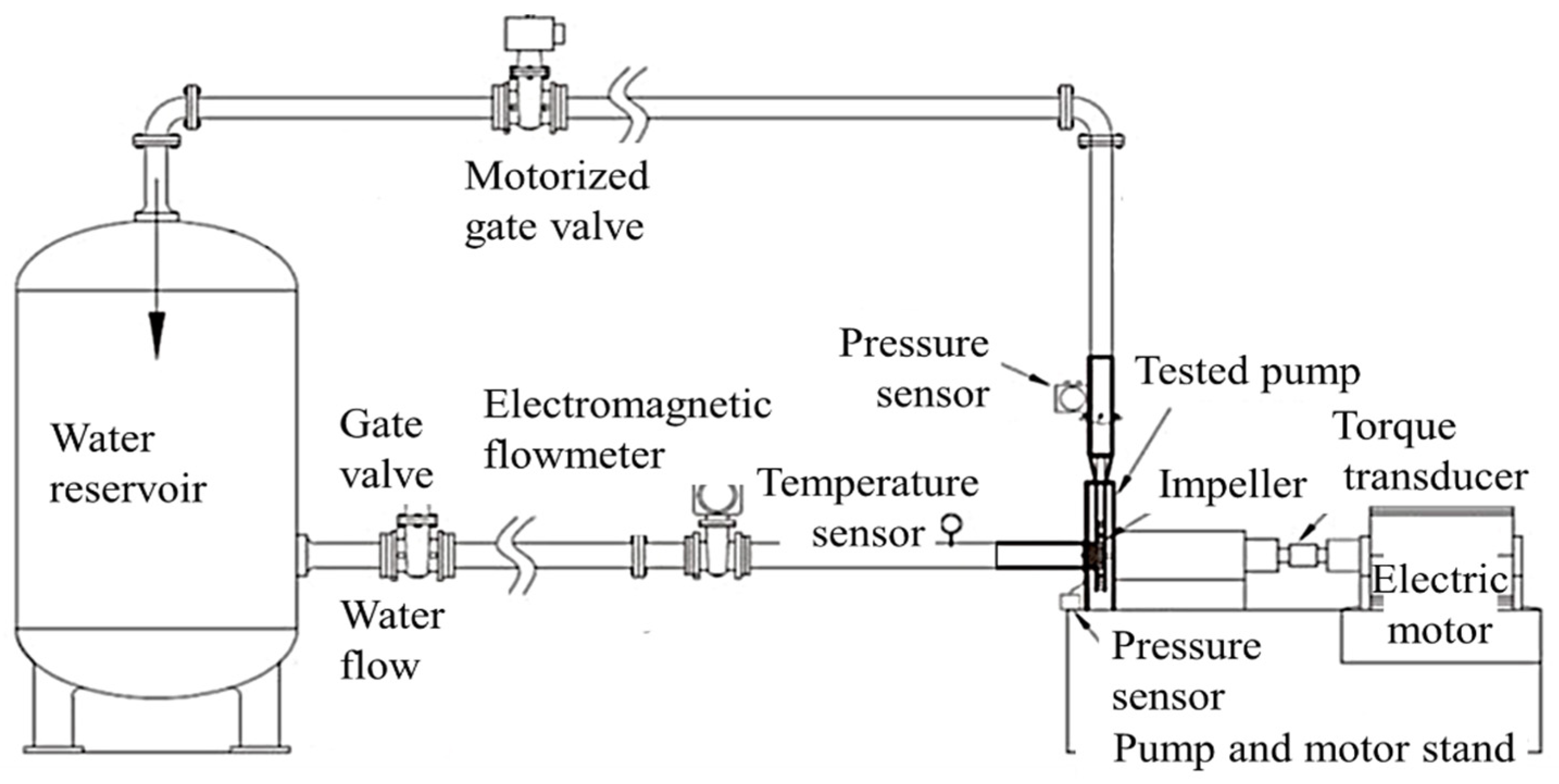
3.2. Test Setup to Validate Numerical Method

It is necessary to compare CFD results with the test data to verify the accuracy of numerical simulation [34]. The LSSCP performance tests were carried out at the State Key Laboratory of Fluid Power & Mechatronic Systems at Hangzhou, China [35]. The schematics of the test rig is described in Figure 3. The flow rate Q was measured by an electromagnetic flowmeter with an accuracy of 0.5%. The torque transducer with an accuracy of 0.5% was adopted to measure the rotational speed n. Two pressure sensors with an accuracy of 0.5% were utilized to measure the pressure of inlet and outlet [36].
Since the hydraulic loss and leakage ring in LSSCP are not considered in the numerical simulation, there is no comparability between the hydraulic efficiency and shaft power obtained from numerical simulation and the efficiency and shaft power measured from the test. Hence, the head was selected as the comparison object in both non-cavitation and cavitation conditions. The result of comparison in the non-cavitation conditions is presented in Figure 4a. In the extreme part load conditions (0.2Qd–0.45Qd), the CFD values of the head have a large error with the test values.
However, there is a satisfactory consistency between the results of CFD and the test with an increase of flow rate. In the condition of Qd, the absolute error between numerical calculation and the test result is 0.67%. Figure 4b shows the comparison of the simulation and the test results of the cavitation performance in the condition of Qd. With the decrease of the net positive suction head available (NPSHa), the feature of a “sudden” head-drop was accurately predicted by the CFD. As can be seen from Figure 4, the results of simulation agreed well with that of the test, indicating the feasibility of the numerical method for predicting non-cavitation and cavitation flow in LSSCP.

4. Results and Discussion

4.1. DVs and Objective Functions

The sensitivity directly reflects the importance of the profile parameters. Main profile parameters with high sensitivity will be extracted as DVs through sensitivity analysis. The range of the main profile parameters was determined according to the fluid properties, design specifications, and the size of LSSCP, listed in Table 3. A set of values was randomly selected within the range of six profile parameters. The rate of change of performance parameters is divided by the growth rate of profile parameters, and the sensitivity value of profile parameters corresponding to each performance parameters can be obtained, as shown in Table 4. D2, b2, and β2 are highly sensitive to H, ηh, and P. Therefore, these three profile parameters are selected as DVs in the global optimization.
One of the optimization objectives in this paper is the suction capability of the LSSCP, and the most important parameter to characterize suction capability is net positive suction head (NPSH) measured during cavitation. In the traditional method of using CFD to predict the NPSH critical (NPSHc), it takes a lot of numerical simulation to gradually gain on the 3% head-drop point at each flow condition. Moreover, it spends a long time to reach a balanced solution because of the time demanded in cavitation bubble development at each numerical simulation in the prediction procedure, which is very time-consuming [37]. On the basis of previous research, a new prediction method is presented.
The lower the value of the NPSH is, the greater the possibility of cavitation is. NPSH can be calculated as follows,
  N P S H = P in P v ρ g
where Pin, and Pv are inlet total pressure and vapor pressure of the fluid, respectively. The value of NPSH decreases as Pin drops. Thus, it is easy to generate cavitation in LSSCP when the inlet pressure Pin is low, resulting in weak suction capability of LSSCP. When performing the multiphase flow cavitation simulation in this paper, the inlet total pressure of LSSCP is specified to be 0.2 atm (20,265 Pa). The head in the cavitation conditions can be obtained, which will decrease compared to that in the non-cavitation condition.
Δ H = H H c H
In one flow condition, ΔH and Hc represent the head down ratio and the head in the cavitation condition, respectively. When cavitation occurs, the bubbles are coagulated and collapsed. This phenomenon leads to the formation of holes in the liquid, causing a local hydraulic impact on the impeller. The cavitation shaft power Pc can reflect the degree of instability inside the impeller in the cavitation condition. Hence, the head reduction ratio ΔH and the cavitation shaft power Pc are used to characterize the suction capability of LSSCP to reduce the calculation time. They are also used in this paper as two optimization objectives.
H, ηh, P in the steady-state and non-cavitation conditions and ΔH, Pc in the cavitation condition with the design flow rate Qd are selected as the optimization objectives in the global optimization. Mathematical descriptions of the many-objective optimization problem of LSSCP are as follows,
{ Minimize   P = f 1 ( x ) Maximize   H = f 2 ( x ) Maximize   η h = f 3 ( x ) Minimize   Δ H = f 4 ( x ) Minimize   P c = f 5 ( x )   x = [ D 2 , b 2 , β 2 ] D 2 [ 360 mm , 410 mm ] b 2 [ 24 mm , 34 mm ] β 2 [ 15 ° , 25 ° ]
where f1~f5 are the objective functions.

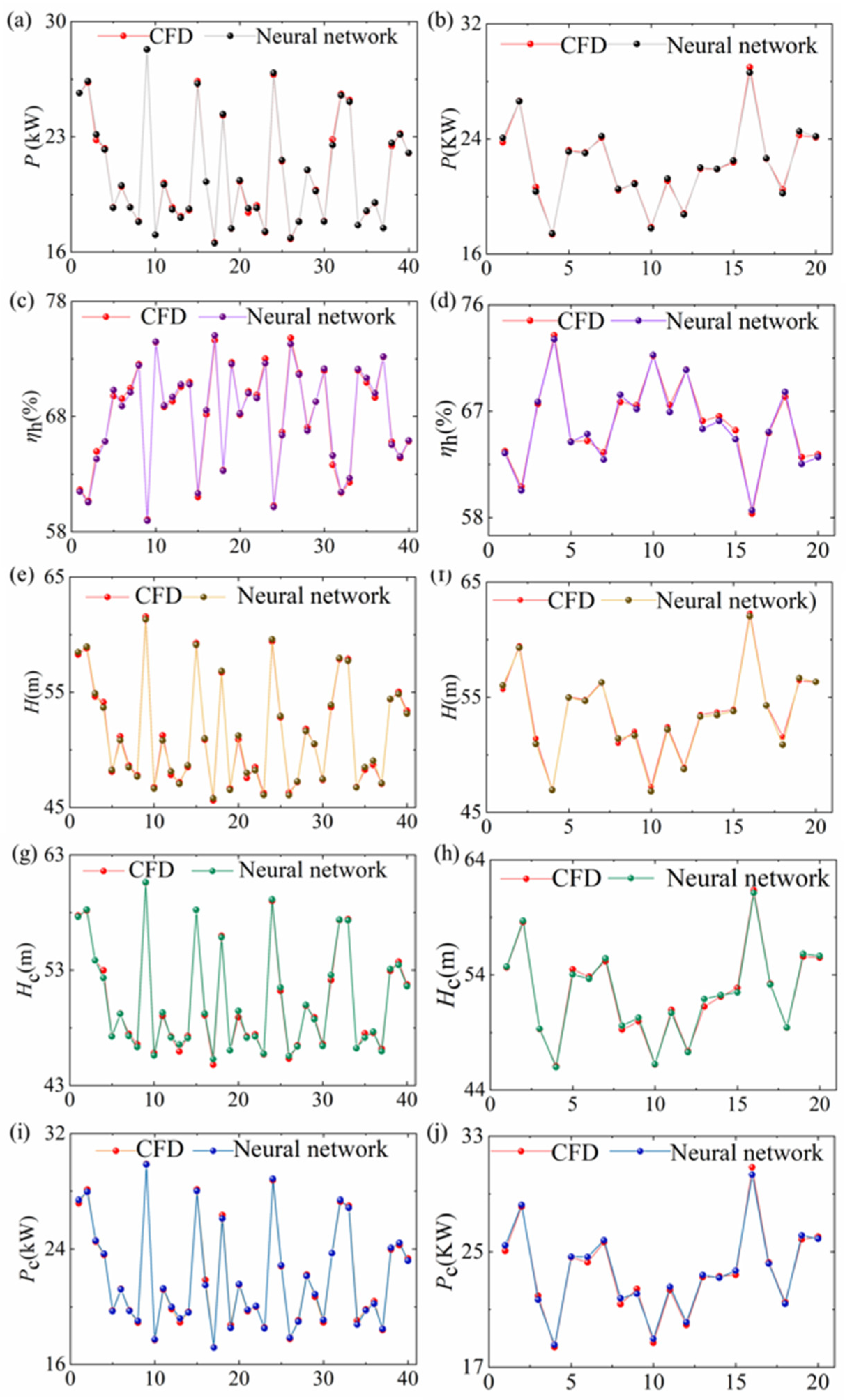
4.2. BPNN Model Verification

A sample library was established by mapping 60 sets of optimization objectives ([P, H, ηh, Hc, Pc]) to 60 sets of DVs ([D2, b2, β2]). Figure 5 presents the fitting results and the predicting results of optimization objectives using BPNN. What can be clearly seen in Figure 5 is the fitting results and the predicting results are in good agreement with the CFD simulation results. Hence, the BPNN is introduced to establish an accurate approximate functional mapping between the optimization objectives and DVs.

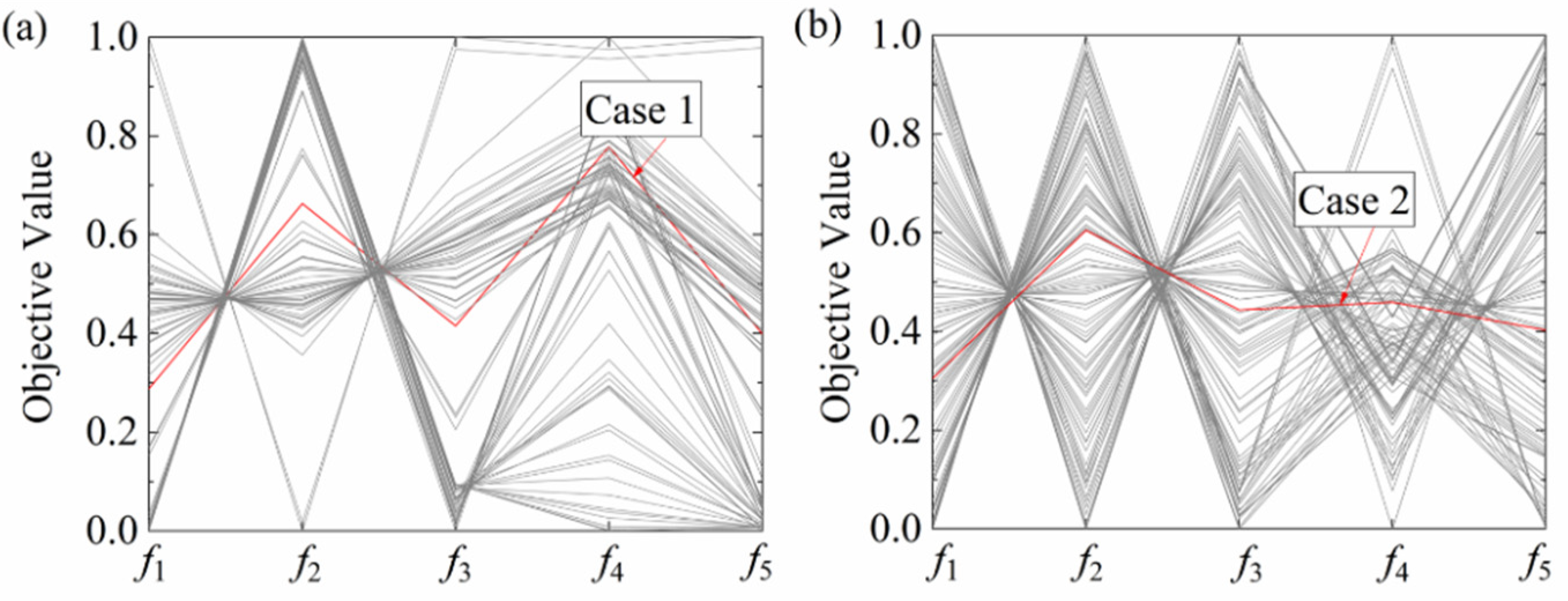
4.3. Result of Optimization

NSGA-II and NSGA-III were used to optimize the performance of LSSCP and compared with the hybrid optimization algorithm proposed in this paper. The population size employed by all algorithms is 100, and the maximum generation number is 500. According to the ISO 5199 Technical specifications for centrifugal pumps—Class II and the performance parameters of LSSCP, optimization objectives in the Pareto solution set were further screened, which is P ≤ 21kW, H ≥ 51m, ηh ≥ 69%, ΔH ≤ 3%, and Pc ≤ 22kW [38].
Figure 6 shows the Pareto frontiers optimized by NSGA-II and NSGA-III using value path format after the min-max normalization of the optimization results. The min-max normalization method is:
τ   =   τ     τ min τ max     τ min
where τ , τ , τ max , and τ min are normalization, raw, maximum, and minimum Pareto frontiers of 5 objectives, respectively. Case 1 and Case 2 are two sets of optimization results of NSGA-II and NSGA-III screened according to ISO 5199 [30], respectively. By comparing Figure 6a,b, it can be found that some population members in NSGA-II which do not meet the constraints may be directly discarded, while NSGA-III generates more uniform reference points in the feasible region, and increases population diversity. Table 5 shows the DVs and optimization objectives values of original and NSGA-II and NSGA-III optimized scheme. Compared with Case 0, after the optimization of the two methods, both of the performance parameters of LSSCP have made significant progress.
In the hybrid optimization algorithm, the adjoint method was used to continue the optimization (Case 3) based on the optimal solution of NSGA-III (Case 2), and ηh, which is the most important performance of LSSCP, was taken as the optimization objective. Figure 7a presents the changes of hydraulic performance of LSSCP during adjoint method optimization. N is the number of optimization iteration. As N increases, ηh gradually increases by 4.7%. P decreases to 18.73 kW. Although H is reduced, it is still higher than 50m which is the designed head. Figure 7b shows the profile of impellers obtained before and after the adjoint method optimization. The comparison of the meridional shapes shows that the profile line at the entrance of the shroud becomes smooth. The blade pressure side is modified by adjoint optimization method, and the bending of the blades has been increased.

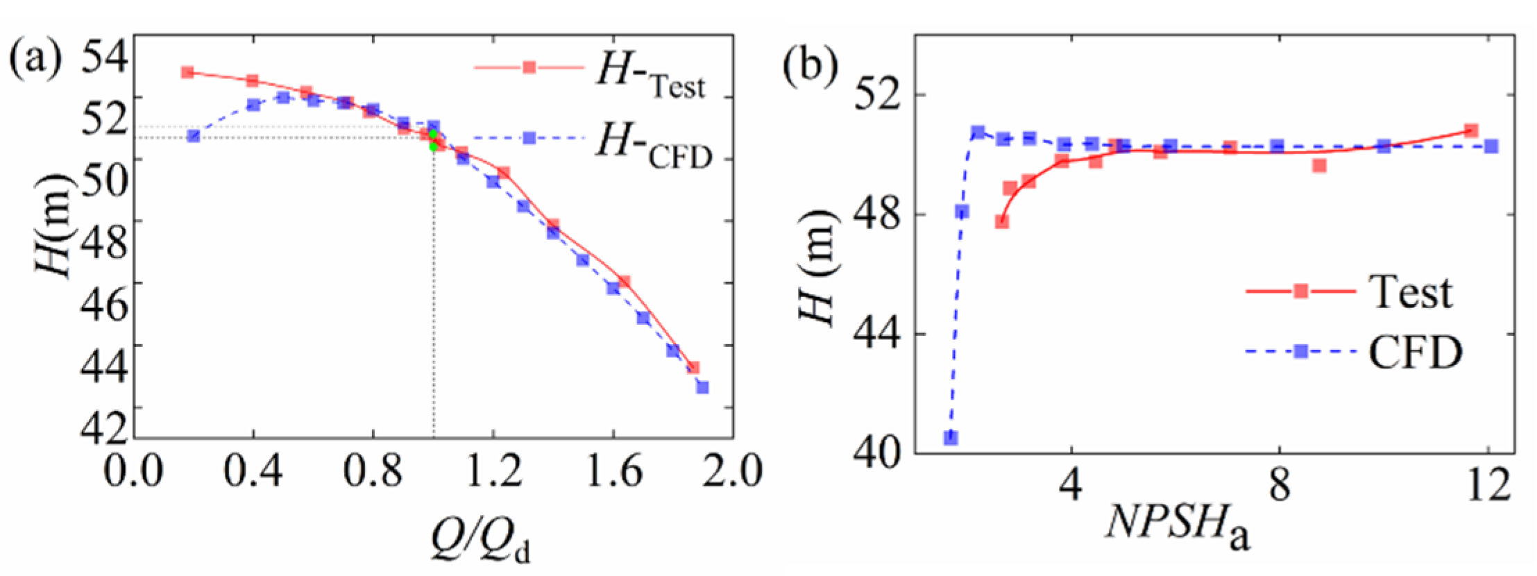
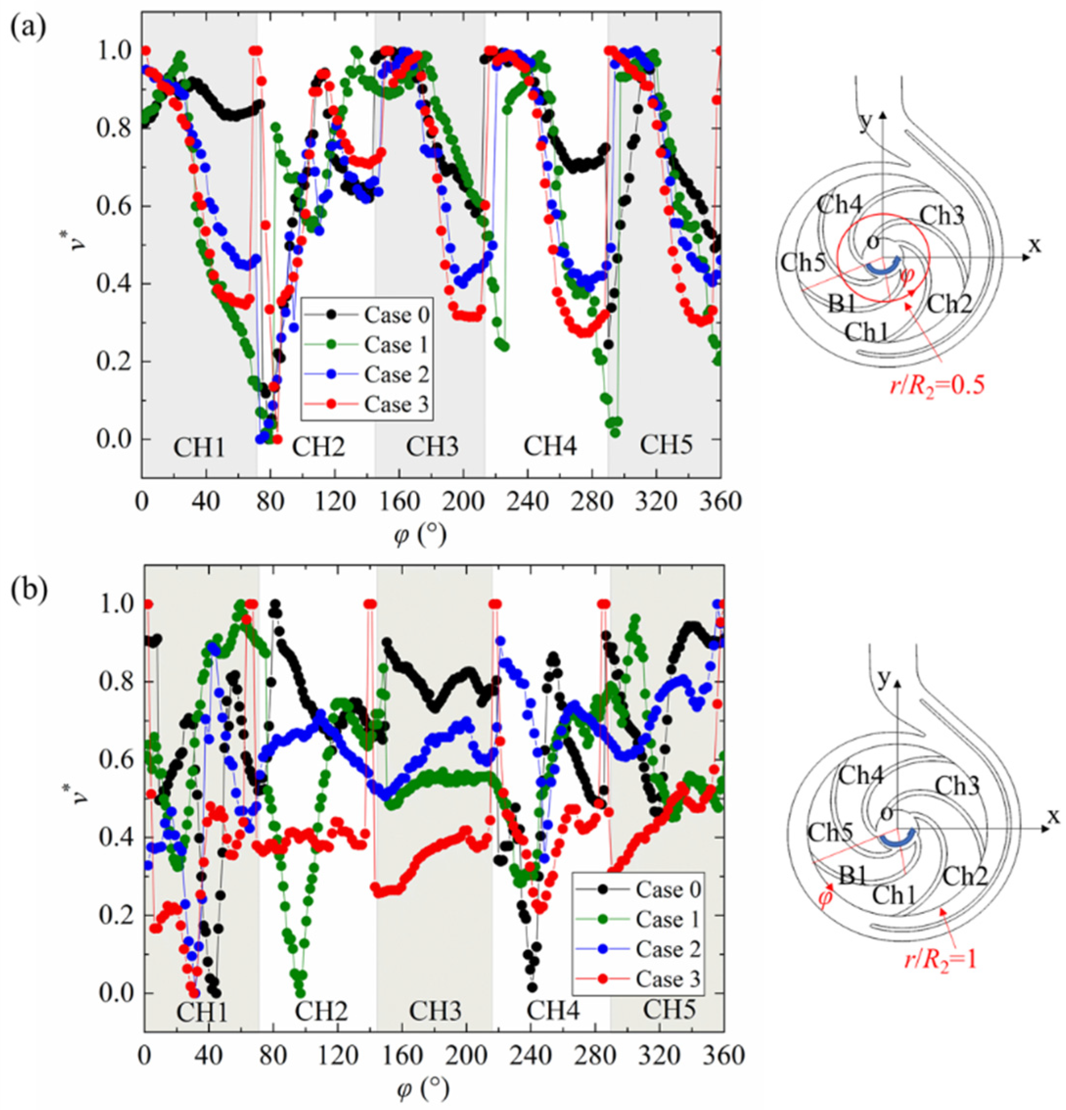
4.4. Hydraulic Performance

Hydraulic performance of four cases in the steady-state and non-cavitation conditions are presented in Figure 8a–c. It can be seen from Figure 8a that ηh of Case 3 is always the highest in each flow condition. In the ultra-low flow conditions (Q/Qd < 0.8), ηh of Case 1 is always the lowest. In the flow condition of Qd, ηh of Case 3 is higher than that of Case 0, 1, and 2 by 9.5%, 5.4%, and 4.7%, respectively. In the high flow conditions, the increase of ηh of Case 1 exceeds that of Case 2. In Figure 8b, P of the four cases all increases as the flow rate increases, where P of Case 3 is always lower than that of Case 0 and Case 2. In the flow condition of Qd, P of Case 3 is 10.3%, 8.7% and 5.1% lower than that of Case 0, 1, and 2, respectively. In Figure 8c, H of Cases 0, 1, and 2 are all significantly reduced, while the head reduction of Case 3 is relatively stable in high flow conditions. In the flow condition of Q/Qd = 1, H-Case3 is higher than the designed head, which is 50 m. Hence, in the steady state and non-cavitation conditions, although the hydraulic performance of LSSCP of the three optimized cases has been significantly improved compared to Case 0, the three performance parameters of Case 3 are more excellent than those of Cases 1 and 2.
Figure 8d shows the NPSHa-H curves of the four cases in the design point Qd. The head of Case 0 drops sharply when the NPSHc of Case 0 is 2.897 m, indicating that the suction capability of the original LSSCP model is weak. Before incipient cavitation occurs, the head of Case 1 was higher than that of Case 0, but its NPSHc was similar to that of Case 0, which proves the suction capability of Case 1 did not significantly improve. The NPSHc of Case 2 and 3 are both around 0.857 m, which is reduced by 70% compared with the original structure and NSGA-II optimization results, and verifies that the suction capability of the two cases has been remarkably improved.
The performance of LSSCP are closely correlated to the internal flow field. Thus, the flow field of LSSCP of four cases is analyzed. Figure 9 shows the velocity and turbulent kinetic energy of the impellers at the condition of steady-state and non-cavitation conditions of Qd. As can be seen from Figure 9a, for Case 0, the high kinetic energy gradient between the pressure side and the suction side of the impeller causes uneven distribution of turbulent kinetic energy. Turbulent kinetic energy on the pressure side reaches 3.5 J/kg, leading to the formation of large-scale vortices in the blade passage. Due to the influence of the centrifugal force and the tangential force at the vortices, obvious backflows occur on the outlet of the impeller, which have negative impact on the hydraulic performance of the original LSSCP. These results are consistent with data obtained in Figure 8, which showed that all performance parameters of Case 0 are unsatisfactory in Qd.
In case 1 of Figure 9b, vortices occur again on the blade passage, and turbulent kinetic energy at the serious backflows reach 6.7 J/kg. For Case 2 in Figure 9c, the size of the vortices is restrained, and the backflow on the impeller outlet is improved compared with Case 0. In Figure 9d, the turbulent kinetic energy in the flow passage is remarkably reduced by modifying the curvature of the blade pressure side, and the maximum is only 2.2 J/kg, which is 4.5 J/kg and 1.9 J/kg less than that of Case 1 and Case 2, respectively. Vortices and backflows basically disappear, and streamlines tend to be uniform in the flow passage, which supports the optimal hydraulic efficiency of Case 3 in the condition of steady-state and non-cavitation conditions of Qd in Figure 8a.
To quantitatively investigate the effect of the hybrid optimization algorithm, relative velocities v* in 5 blade channels of Case 0–3 under the condition of steady-state and non-cavitation conditions of Qd are selected for comparison, as shown in Figure 10. Upper right corner of Figure 10a,b presents relative velocity extraction trajectory diagram of LSSCP. The blade channels Ch1–5 are analyzed and relative velocities at the r/R2 = 0.5 and r/R2 = 1 (R2 is each impeller outlet radius) are extracted. The angle of pressure side point of the blade B1 is defined as φ = 0°. φ increases in the direction of impeller rotation.
It can be seen from Figure 10a that there is non-uniform flow in each channel in the four cases. In Case 0, both Ch2 and Ch5 have low-velocity areas, resulting in a large velocity gradient inside the channel, which corresponds to the large vortices on the pressure side of the blades in Figure 9a. In Case 1, there is a large gradient between the high-velocity area and the low-velocity area in each channel, and a low-velocity area suddenly appears in the center of Ch2, causing the channel to be blocked by the low-velocity vortex. Case 2 is similar to Case 1, but the velocity gradient of each channel is smaller, and there is a large low-velocity vortex on the pressure side of Ch2. The internal flow of Case 3 is more uniform than that of Case 0–2, and there is a smaller low- velocity area at φ = 80–85° in Ch2. In Figure 10b, there are large-area low-velocity vortices blocking the outlet of the impeller in Ch1, 4, and 5 of Case 0, and the velocity gradient causes jet and wake. In Case 1, the large-area low-velocity areas are captured in Ch1, 2, and 4, and the vortices at the outlet leads to increased flow loss. The vortices of Case 2 are significantly reduced compared with Case 1, but the velocity difference between jet and wake is still large, which is detrimental to the performance of the pump. There are no large-area vortices at the outlet of the impeller of Case 3, only slight jet-wake flow pattern exists in Ch1 and 4. Therefore, the hydraulic loss of Case 3 is less than that of Case 0–2, which contributes to the increase of hydraulic efficiency and decrease of shaft power of LSSCP, as shown in Figure 8.
The transient calculation of the cavitation flow field of LSSCP in the design point Qd was performed. Figure 11 shows the distribution of the vapor volume in the impeller as NPSHa decreases. In Figure 11a,b, when NPSHa = 2.897, the vapor has appeared at the inlet of the impeller of the models of Cases 0 and 1. At this condition, the head of the two models drops suddenly, as shown in Figure 8d. When the NPSHa is reduced to 0.857 m, the inlet of the impeller of the Case 0 and 1 is blocked by vapor, resulting in worse flow and severe cavitation. For Cases 2 and 3 in Figure 11c,d, the vapor volume of the impeller is significantly reduced. When NPSHa = 2.897 m, both Cases 2 and 3 have a small point-like vapor distribution at the inlet of the impellers, which will not have a large impact on the flow. Compared with Case 2, Case 3 has less vapor in the impeller when NPSHa = 0.857.

5. Conclusions

This research proposes a hybrid optimization algorithm by combining NSGA-III and the adjoint method to improve the optimal performance of the pump as much as possible. The head, hydraulic efficiency, shaft power, and suction capability at a specific flow rate are optimized. We chose NSGA-III, which is better at solving many-objective optimization problem, and compared it with NSGA-II. While both algorithms can yield better performance than the original LSSCP, the NSGA-III produced more uniform reference points, increasing the diversity of optimized objective. The adjoint method was carried out after applying NSGA-III, which can converge quickly and correct the errors introduced by the BPNN. The profile line at the entrance of the shroud becomes smooth and the outlet distance of impeller increases, which have an active influence on the efficiency of LSSCP. Performance and flow field of the model obtained by NSGA-II, NSGA-III, and hybrid optimization were compared with the original LSSCP. In the designed flow condition of non-cavitation, compared with the original, NSGA-II optimized and NSGA-III optimized, and the hydraulic efficiency obtained by applying the hybrid optimization algorithm is increased by 9.5%, 5.4%, and 3.8%, respectively, and the shaft power is decreased by 10.3%, 8.7%, and 5.1%, respectively. The large-area vortices in the impeller obtained from the hybrid optimization has basically disappeared and the hydraulic loss is obviously reduced. In the cavitation conditions with Qd, when the head drops sharply, the NPSHc of hybrid optimized model is lower than that of the other model, which significantly improves the suction capability of LSSCP. The purpose of this research is to propose and validate the idea of using a hybrid optimization method to improve the performance of LSSCP that is widely used in district energy system. Due to limited experimental condition, the size of the studied pump is employed only for validating the many-objective optimization method which can be further applied to other pumps with different sizes in district energy system.

Author Contributions

Conceptualization, Z.T. and J.X.; methodology, Z.T.; software, J.X.; validation, Z.T., J.X..; formal analysis, J.X.; investigation, Z.T.; resources, C.L.; data curation, J.X. and C.L.; writing—original draft preparation, Z.T. and J.X.; writing—review and editing, Z.T. and J.X.; visualization, J.X.; supervision, Z.T.; project administration, Z.T.; funding acquisition, Z.T. All authors have read and agreed to the published version of the manuscript.

Funding

This research was funded by the National Natural Science Foundation of China (52075481,52075477) and the Zhejiang Provincial Natural Science Foundation (LR19E050002).

Institutional Review Board Statement

Not applicable.

Informed Consent Statement

Not applicable.

Conflicts of Interest

The authors declare no conflict of interest.

References

  1. Paredes-Sanchez, B.M.; Paredes, J.P.; Caparrini, N.; Rivo-Lopez, E. Analysis of District Heating and Cooling Energy Systems in Spain: Resources, Technology and Management. Sustainability 2021, 13, 5442. [Google Scholar] [CrossRef]
  2. Sarbu, I.; Valea, E.S. Energy Savings Potential for Pumping Water in District Heating Stations. Sustainability 2015, 7, 5705–5719. [Google Scholar] [CrossRef] [Green Version]
  3. Pei, J.; Wang, W.J.; Yuan, S.Q.; Zhang, J.F. Optimization on the Impeller of a Low-specific-speed Centrifugal Pump for Hydraulic Performance Improvement. Chin. J. Mech. Eng. 2016, 29, 992–1002. [Google Scholar] [CrossRef]
  4. Zhang, R.H.; Chen, X.B.; Luo, J.Q. Knowledge Mining of Low Specific Speed Centrifugal Pump Impeller Based on Proper Orthogonal Decomposition Method. J. Therm. Sci. 2020, 30, 840–848. [Google Scholar] [CrossRef]
  5. Zhao, A.; Lai, Z.N.; Wu, P.; Cao, L.L.; Wu, D.Z. Multi-objective optimization of a low specific speed centrifugal pump using an evolutionary algorithm. Eng. Optim. 2016, 48, 1251–1274. [Google Scholar] [CrossRef]
  6. Kaya, D.; Yagmur, E.A.; Yigit, K.S.; Kilic, F.C.; Eren, A.S.; Celik, C. Energy efficiency in pumps. Energy Convers. Manag. 2008, 49, 1662–1673. [Google Scholar] [CrossRef]
  7. Derakhshan, S.; Pourmahdavi, M.; Abdolahnejad, E.; Reihani, A.; Ojaghi, A. Numerical shape optimization of a centrifugal pump impeller using artificial bee colony algorithm. Comput. Fluids 2013, 81, 145–151. [Google Scholar] [CrossRef]
  8. Wang, W.J.; Li, Y.P.; Osman, M.K.; Yuan, S.Q.; Zhang, B.Y.; Liu, J. Multi-Condition Optimization of Cavitation Performance on a Double-Suction Centrifugal Pump Based on ANN and NSGA-II. Processes 2020, 8, 1124. [Google Scholar] [CrossRef]
  9. Safikhani, H.; Khalkhali, A.; Farajpoor, M. Pareto Based Multi-Objective Optimization of Centrifugal Pumps Using CFD, Neural Networks and Genetic Algorithms. Eng. Appl. Comput. Fluid Mech. 2011, 5, 37–48. [Google Scholar] [CrossRef] [Green Version]
  10. Yang, W.; Xiao, R.F. Multiobjective Optimization Design of a Pump–Turbine Impeller Based on an Inverse Design Using a Combination Optimization Strategy. J. Fluids Eng. 2014, 136. [Google Scholar] [CrossRef]
  11. Wang, W.J.; Osman, M.K.; Pei, J.; Gan, X.C.; Yin, T.Y. Artificial Neural Networks Approach for a Multi-Objective Cavitation Optimization Design in a Double-Suction Centrifugal Pump. Processes 2019, 7, 246. [Google Scholar] [CrossRef] [Green Version]
  12. Derakhshan, S.; Bashiri, M. Investigation of an efficient shape optimization procedure for centrifugal pump impeller using eagle strategy algorithm and ANN (case study: Slurry flow). Struct. Multidiscip. Optim. 2018, 58, 459–473. [Google Scholar] [CrossRef]
  13. Liu, X.W.; Li, H.C.; Shi, X.X.; Fu, J.F. Application of biharmonic equation in impeller profile optimization design of an aero-centrifugal pump. Eng Comput. 2019, 36, 1764–1795. [Google Scholar] [CrossRef]
  14. Wang, X.D.; Hirsch, C.; Kang, S.; Lacor, C. Multi-objective optimization of turbomachinery using improved NSGA-II and approximation model. Comput. Methods Appl. Mech. Eng. 2011, 200, 883–895. [Google Scholar] [CrossRef]
  15. Pei, J.; Wang, W.J.; Yuan, S.Q. Multi-point optimization on meridional shape of a centrifugal pump impeller for performance improvement. J. Mech. Sci. Technol. 2016, 30, 4949–4960. [Google Scholar] [CrossRef]
  16. Benturki, M.; Dizene, R.; Ghenaiet, A. Multi-Objective Optimization of Two-Stage Centrifugal Pump using NSGA-II Algorithm. J. Appl. Fluid Mech. 2018, 11, 929–943. [Google Scholar] [CrossRef]
  17. Tong, S.G.; Zhao, H.; Liu, H.Q.; Tong, Z.M.; Yu, Y.; Tang, N.; Wu, W.J.; Li, J.f.; Cong, F.Y.; Zhang, H. Optimization calculation method for efficiency of multistage split case centrifugal pump. J. ZheJiang Univ. (Eng. Sci.) 2019, 53, 988–996. [Google Scholar] [CrossRef]
  18. Deb, K.; Jain, H. An Evolutionary Many-Objective Optimization Algorithm Using Reference-Point-Based Nondominated Sorting Approach, Part I: Solving Problems With Box Constraints. Ieee T Evol. Comput 2014, 18, 577–601. [Google Scholar] [CrossRef]
  19. Verstraete, T.; Mueller, L. Adjoint-Based Multi-Point and Multi-Objective Optimization of a Turbocharger Radial Turbine. Int. J. Turbomach. Propuls. Power 2019, 4, 10. [Google Scholar] [CrossRef] [Green Version]
  20. Namgoong, H.; Crossley, W.; Lyrintzis, A. Global Optimization Issues for Transonic Airfoil Design. Aiaa/Issmo Symp. Multidiscip. Anal. Optim. 2013. [Google Scholar] [CrossRef]
  21. Wang, H.; Wang, H.; Zhu, T. A new hydraulic regulation method on district heating system with distributed variable-speed pumps. Energy Convers. Manag. 2017, 147, 174–189. [Google Scholar] [CrossRef]
  22. Kuosa, M.; Kontu, K.; Mäkilä, T.; Lampinen, M.; Lahdelma, R. Static study of traditional and ring networks and the use of mass flow control in district heating applications. Appl. Therm. Eng. 2013, 54, 450–459. [Google Scholar] [CrossRef]
  23. Zhang, J.J. Development of Performance Prediction Software for Low Specific Speed Centrifugal Pump. Water Sav. Irrig. 2009, 46–49. [Google Scholar] [CrossRef]
  24. Siddique, M.H.; Afzal, A.; Samad, A. Design Optimization of the Centrifugal Pumps via Low Fidelity Models. Math. Probl. Eng. 2018, 2018, 1–14. [Google Scholar] [CrossRef]
  25. Jameson, A. Aerodynamic design via control theory. J. Sci. Comput. 1988, 3, 233–260. [Google Scholar] [CrossRef] [Green Version]
  26. Callejo, A.; Bauchau, O.A.; Diskin, B. Adjoint method for the sensitivity analysis of composite beam cross-sections. Comput Struct 2019, 213, 100–111. [Google Scholar] [CrossRef]
  27. Li, Y.; Tong, Z. Development of real-time adaptive model-free extremum seeking control for CFD-simulated indoor thermal environment. Sustain. Cities Soc. 2021, 5, 103166. [Google Scholar] [CrossRef]
  28. Shim, H.S.; Afzal, A.; Kim, K.Y.; Jeong, H.S. Three-objective optimization of a centrifugal pump with double volute to minimize radial thrust at off-design conditions. Proc. Inst. Mech. Eng. Part A J. Power Energy 2016, 230, 598–615. [Google Scholar] [CrossRef]
  29. Li, W.; Agarwal, R.K.; Zhou, L.; Li, E.; Ji, L. Effect of Tip Clearance on Rotating Stall in a Mixed-Flow Pump. In Proceedings of the ASME Turbo Expo 2019: Turbomachinery Technical Conference and Exposition, Phoenix, AZ, USA, 17–21 June 2019. [Google Scholar]
  30. Chen, Z.; Jiang, Y.; Tong, Z.; Tong, S.; Tan, J. Fatigue Analysis of Spherical Contact Subjected to Cyclic Elastic-Plastic Normal Loading. ASME J. Tribol. 2021, 143, 074502. [Google Scholar] [CrossRef]
  31. Chen, Z.; Jiang, Y.; Tong, Z.; Tong, S. Residual Stress Distribution Design for Gear Surfaces Based on Genetic Algorithm Optimization. Materials 2021, 14, 366. [Google Scholar] [CrossRef]
  32. Tong, Z.; Xin, J.; Tong, S.; Yang, Z.; Zhao, J.; Mao, J. Internal flow structure, fault detection, and performance optimization of centrifugal pumps. J. Zhejiang Univ. Sci. A 2020, 21, 85–117. [Google Scholar] [CrossRef]
  33. Tong, Z.; Cheng, Z.; Tong, S. A review on the development of compressed air energy storage in China: Technical and economic challenges to commercialization. Renew. Sustain. Energy Rev. 2021, 135, 110178. [Google Scholar] [CrossRef]
  34. Tong, Z.; Cheng, Z.; Tong, S. Preliminary Design of Multistage Radial Turbines Based on Rotor Loss Characteristics under Variable Operating Conditions. Energies 2019, 12, 2550. [Google Scholar] [CrossRef] [Green Version]
  35. Tong, Z.; Chen, Y.; Tong, S.; Yu, Y.; Li, J. Multi-objective optimization design of low specific speed centrifugal pump based on NSGA-III algorithm. China Mech. Eng. 2019, 1–9. [Google Scholar] [CrossRef]
  36. Zhang, Q.; Tong, Z.; Tong, S.; Cheng, Z. Research on water and heat management in the cold start process of proton exchange membrane fuel cell with expanded graphite bipolar plate. Energy Convers. Manag. 2021, 233. [Google Scholar] [CrossRef]
  37. Ding, H.; Visser, F.C.; Jiang, Y. A Practical Approach To Speed up Npshr Prediction of Centrifugal Pumps Using Cfd Cavitation Model. In Fluids Engineering Division Summer Meeting; American Society of Mechanical Engineers: New York, NY, USA, 2012; pp. 505–514. [Google Scholar]
  38. Technical Specifications for Centrifugal Pumps—Class II (ISO 5199:2002). Available online: https://www.sis.se/api/document/preview/32285/ (accessed on 4 September 2021).
Figure 1. The hybrid optimization process of LSSCP.
Sustainability 13 10537 g001
Figure 2. Schematic of the original structure and computational domain for numerical analysis: (a) meridional section; (b) blade angles; (c) fluid domain mesh.
Sustainability 13 10537 g002
Figure 3. Scheme of the test rig.
Sustainability 13 10537 g003
Figure 4. Head of the test and numerical results in the (a) non-cavitation conditions and (b) cavitation conditions with Qd.
Sustainability 13 10537 g004
Figure 5. Fitting results and predicting results. (a) Fitting results of P, (b) Predicting results of P, (c) Fitting results of ηh, (d) Predicting results of ηh, (e) Fitting results of H, (f) Predicting results of H, (g) Fitting results of HC, (h) Predicting results of HC, (i) Fitting results of PC, and (j) Predicting results of PC.
Sustainability 13 10537 g005
Figure 6. Pareto frontiers optimized by (a) NSGA-II and (b) NSGA-III.
Sustainability 13 10537 g006
Figure 7. (a) The change of the hydraulic efficiency, shaft power, and head in the adjoint method optimization. (b) Comparison of profile of the impellers obtained before and after the adjoint method optimization.
Sustainability 13 10537 g007
Figure 8. Performance curves of (a) ηh, (b) P, and (c) H in the steady-state and non-cavitation conditions, and (d) NPSHa-H curves at the rated flow of cavitating condition.
Sustainability 13 10537 g008
Figure 9. Velocity streamline and turbulent kinetic energy of (a) Case 0, (b) Case 1, (c) Case 2, and (d) Case 3 at the condition of steady-state and non-cavitation conditions of Qd.
Sustainability 13 10537 g009
Figure 10. Comparison of relative velocities at (a) r/R2 = 0.5 and (b) r/R2 = 1 under the condition of steady-state and non-cavitation conditions of Qd.
Sustainability 13 10537 g010
Figure 11. The distribution of the vapor volume in the impeller of (a) Case 0, (b) Case 1, (c) Case 2, and (d) Case 3 in the design point Qd.
Sustainability 13 10537 g011
Table 1. Summary of design variables and optimization algorithms for centrifugal pump optimization.
ReferenceDesign VariablesOptimization Objectives MethodOptimization Algorithm
Safikhani et al. [9]Leadingedge angle, trailing edge angle, and stagger angleEfficiency and net positive suction head required (NPSHr)CFDMOGA
Yang and Xiao. [10] Impeller high-pressure and low-pressure side diameter, impeller low-pressure side hub diameter, impeller high-pressure side exit widthHydraulic efficiency in differient mass flow rateCFD and ExperimentMOGA
Wang et al. [11]Hub inlet angle, hub exit angle, hub wrap angle, leading-edge wrap angle at hub, shroud inlet angle, shroud exit angle, shroud wrap angle, and the leading edge wrap angle at the shroudEfficiency and NPSHrCFD and ExperimentMOGA
Derakhshan et al. [7]Hub diameter, suction diameter, impeller diameter, impeller width, inlet, and outlet blade anglesEfficiency and total pressure differenceCFD and ExperimentABC
Derakhshan and M. Bashiri. [12]Hub diameter, suction diameter, impeller diameter, impeller width, and inlet and outlet blade angles Efficiency and total pressure differenceCFD and ExperimentES
Liu et al. [13]Hub streamline and shroud streamlineHydraulic efficiencyCFD and ExperimentAFSA
Wang et al. [14]Four angles for the sweep and leanEfficiencies at two working points and total pressure ratioCFDNSGA-II
Zhao et al. [5]Blade outlet angle, blade inlet angle, splitter offset angle, impeller meridional sectionAnti-cavitation ability and the hydraulic efficiencyCFD and ExperimentNSGA-II
Pei et al. [15]The shroud radius, the hub radius, the shroud angle, and the hub angleHydraulic efficiency in differient mass flow rateCFD and ExperimentNSGA-II
Benturki et al. [16]Leading and trailing edge blade angles, impeller blade thickness, wrap anglesHead, hydraulic efficiency, and NPSHrCFD and ExperimentNSGA-II
Tong et al. [17]Impeller outlet diameter, impeller outlet width, and impeller exit angleHead, and hydraulic efficiencyCFDNSGA-II
Table 2. The main profile parameters of the impeller.
Profile ParameterValue
Impeller inlet diameter D1 (mm)112
Impeller outlet diameter D2 (mm)400
Impeller inlet angle β1 (°)16.54
Impeller outlet angle β2 (°)42
Impeller outlet width b2 (mm)30
Blade wrap angle φ (°)130
Number of the impeller blades Z5
Table 3. The range of the main profile parameters.
The Main Profile ParametersRange
D1 (mm) [80, 120]
D2 (mm)[360, 410]
β1 (°)[15, 45]
β2 (°)[15, 45]
b2 (mm)[24, 34]
Z[3, 7]
Table 4. Sensitivity value of profile parameters.
Profile ParametersSHSηhSP
D10.009240.009240.02
D22.334470.048352.28391
β10.025030.015030.01
β20.245530.095650.15017
b20.07930.042370.12178
Z0.035370.041570.03985
Table 5. Original and optimized scheme.
Schemeb2 (mm)D2 (mm)β2 (°)H (m)ηh (%)P (KW)ΔH (%)Pc (KW)
Case 0Original 304004250.6466.0120.93.122.4
Case 1NSGA-II28.85387.116.851.6669.8620.1322.0
Case 2NSGA- III25.16383.216.151.5870.3420.02.921.8
Publisher’s Note: MDPI stays neutral with regard to jurisdictional claims in published maps and institutional affiliations.

