Article

Experimental Study of the Performance of a Laboratory-Scale ESP with Biomass Combustion: Discharge Electrode Disposition, Dynamic Control Unit and Aging Effect

CINTECX, University of Vigo, Lagoas-Marcosende s/n, 36310 Vigo, Spain
*
Author to whom correspondence should be addressed.
Sustainability 2021, 13(18), 10344; https://doi.org/10.3390/su131810344
Submission received: 30 July 2021 / Revised: 8 September 2021 / Accepted: 13 September 2021 / Published: 16 September 2021
(This article belongs to the Special Issue Bioresources and Utilization of Biomass in Sustainability)

Abstract

:
The increasing use of biomass combustion systems as household appliances for heat generation is causing concern about local air quality. Areas with high concentrations of particulate matter (PM) emissions are linked to health risks. There is a need for a removal device that collects the particles before they reach the atmosphere. Electrostatic precipitators (ESPs) are the most suitable option. In this study, a laboratory-scale prototype ESP was tested with a pellet boiler. Retention efficiencies above 90% were obtained with three different discharge electrode dispositions. The continuous operation of the ESP was achieved with a dynamic control system despite fluctuations in emissions, gas conditions, etc. The accumulation of particles on inner ESP surfaces over the operation time reduced the effectiveness of the electric field, and thus retention efficiency. In this study, the retention efficiency fell from 90% to 31% in 34 h.

1. Introduction

The use of renewable energies has become more important in the global energy mix as an alternative to fossil-based resources because of environmental issues and regulatory requirements [1,2]. Biomass is an easy-to-find feedstock and an energy storage itself, which is an advantage in terms of the availability of resources. However, the particulate matter (PM) emissions associated with the combustion process are important concerns [3,4,5].
In particular, the PM emitted by biomass combustion involves fine and ultrafine particles, which are harmful to human health. Areas with a high number of domestic biomass combustion devices increase the exposure of the population to PM. Numerous studies have stated a link between PM concentration in the air and health problems related to respiratory diseases [6,7]. Not all particles are equally toxic and the most harmful effects are related to their size, since smaller particles penetrate into lower airways [6]. Long-term exposure to ultrafine particles smaller than 100 nm is also associated with chronic inflammatory diseases, since the particles reach the circulatory system through the lungs and then secondary organs [7].
There is strong interest in reducing PM emissions from biomass combustion, which can be accomplished through the use of primary or secondary measures. Primary measures involve actions to prevent the formation of PM, and secondary measures are solutions applied to collect particles after they have been formed but before they reach the atmosphere. Different authors have studied primary measures for reducing the formation of PM [5,8,9,10,11,12,13,14,15,16]. However, in some of these cases, the measures may not be sufficient to meet emission requirements. The ecodesign regulation established by the European Union limits the particle matter emissions of automatically and manually stoked solid fuel boilers to 40 and 60 mg/m3, respectively, as measured at 0 °C, 101.3 kPa and 10% O2 [17]. Regulations for reducing PM emissions narrow the limits and demand cleaner combustion devices. The ecodesign regulation applies only to new equipment, leaving the issue of PM emissions from a very large existing fleet unresolved. Therefore, secondary measures are needed to meet the requirements when primary measures are not enough to guarantee good air quality in areas where there are many PM sources.
There are different alternatives to particle removal devices. Scrubbers, bag filters and cyclones have different limitations for treating biomass combustion emissions [18,19]. One of the most common solution for small-scale systems is the electrostatic precipitator (ESP) [20,21,22,23]. Scrubbers show a retention efficiency of 44% for submicron particles (<1 µm), which is considerably lower than the 95% retention efficiency of ESPs [19]. Bag filters are effective particle removal devices with efficiencies up to 99.97%, but the flue gas must be dry, otherwise, particulate cannot be removed properly [18]. The flue gas from biomass combustion is not dry and for small-scale appliances a drying process is not feasible. Cyclones present a retention efficiency of 70% for 5 µm particles and decreased values for smaller size range [18], which is not convenient for biomass combustion emissions.
An ESP is a system that removes PM from flue gas by means of an electric field. This electric field is generated by a high potential discharge electrode, and the particles are collected on an earthed electrode. ESPs are highly efficient for eliminating a wide range of variously sized particles compared to other technologies [18]. As an example, the ESP technology has shown 95% retention efficiency for ultrafine particles (from 0.01 µm) [24] and close to 98% for coarse particles (up to 10 µm) [19]. However, ESP performance can be reduced due to particle layers accumulating on the surfaces of both electrodes. Back corona discharge (BCD) is linked to a reduction in collection efficiency because it interferes with the electric field [25,26]. There is also a link between efficiency decline and operating time due to the layer of particles that is retained [27,28]. The authors of [28] also show that optimum ESP performance is achieved after the inner surfaces of the ESP are cleaned.
Despite good results obtained with different ESP designs [20,23,29,30,31,32], this technology is still emerging [33]. Domestic ESPs need to meet several requirements to make them viable. The design should be small in scale and easily adaptable to different combustion devices, the manufacturing and maintenance costs should be as low as possible, and the ESP needs to be safe, reliable and user-friendly.
This study is focused on testing laboratory-scale ESPs previously presented in [34]. Three different arrangements are tested with various holding points of the discharge electrode to identify the most suitable design. A pellet boiler is used as a PM source. Biomass combustion systems are characterized by fluctuations in their emissions even when a steady state is reached because fluctuations can affect the concentration of particles and condition of flue gas. These variations interfere with the electric field inside the ESP. A novel solution to the unstable operation of an ESP is developed based on a power control system, which ensures long-term operation. Finally, the evolution of the retention efficiency of the optimum ESP design during its operating time is analyzed. The results from this study contribute to increase knowledge of ESP performance with biomass combustion particles, particularly focusing on the effect of the accumulation of particles on the surfaces of the electrodes, and provide an original system to automatically adapt the electrical parameters of ESPs to ensure long-term operation.

2. Materials and Methods

This study focuses on the performance analysis of a laboratory-scale ESP with biomass combustion. The experimental facility consists of an ESP attached to a pellet boiler, PM and gas analyzers distributed as shown in Figure 1.
The biomass combustion system is a small-scale fire-tube boiler coupled to a pellet burner. The power of the burner can be adjusted to the desired level from 14 kWth to 34 kWth. For this study, the power level was fixed at 25 kWth. The gas from the combustion of pellets leaves the boiler to enter the ESP at 180 °C.
Pellets are the most common biomass solid fuel used to feed domestic devices. Pellets consisting of wood were chosen for this study because their combustion is clean and of high quality. Table 1 and Table 2 show the proximate analysis and the ultimate analysis of the pellets, respectively. The amount of ash is low, thus our previous statement about good combustion conditions is supported. Table 3 shows the elemental analysis of the ash.
The PM produced during combustion was characterized before testing the ESP. The particle size distribution and PM mass concentration was determined.
The particle size distribution was measured with a Dekati low pressure impactor (DLPI) and its curve is depicted in Figure 2. The ESP shows good performance for a wide variety of particle sizes (overall retention efficiency above 90% [19,24]), which is a great advantage compared to other abatement devices, as previously mentioned. The average PM mass concentration is 8.4 mg/m3 at 10% O2. Both the concentration and the size distribution agree with the values found in the literature [35,36].
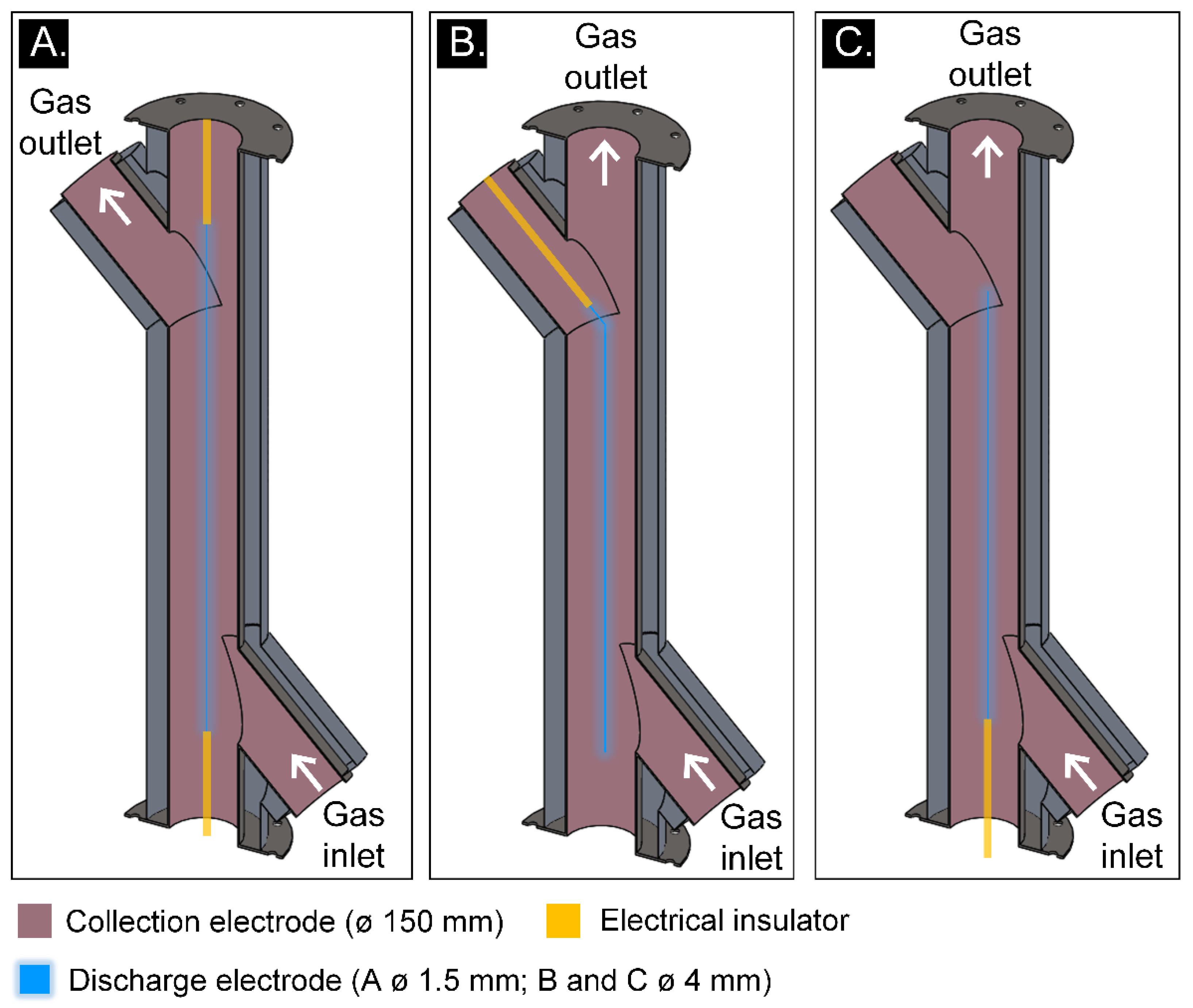
The ESP used in this study is a laboratory-scale tubular-type prototype [34]. It consists of an AISI 316L tube with a 150 mm inner diameter as the collection electrode and two different discharge electrodes. The tests were carried out with either a smooth stainless-steel rod with a 4 mm diameter or a stainless-steel wire with a 1.5 mm diameter. Both were placed in the center of the tube, and their effective lengths were 1.1 m. The height of the tube was 1.7 m.
The tubular shape of the ESP eases to adapt to the chimney, reducing manufacturing cost. In addition, the geometry is designed to prevent gas flow through the physical joint between electrodes, as shown in Figure 3, since this flow path caused problems in previous studies [3,34]. The authors of [3] conclude that conductivity through the electrical insulator increases due to fouling; therefore, to avoid unexpected electrical current due to particle deposition, the structure linking discharge and collection electrodes should not be placed into the gas flow path. The authors of [34] present an alternative design where there is no continuous gas flow through the fixation system, preventing fouling and increasing the lifetime of the equipment under service. The electrical insulators should not be covered by particles (fouling) because this would induce undesirable spark discharges. Periodic cleaning of the insulators helps prevent electrical failures, but this type of cleaning system should be designed and introduced into the ESP, which certainly increases ESP costs and complexity.
Different discharge electrode dispositions were tested, as shown in Figure 3. In the first case (Figure 3A), the discharge electrode is a 1.5 mm diameter wire, which is held at both the top and bottom of the vertical tube. The other options present a different electrode of 4 mm in diameter, which is easier to hold. Therefore, it needs only one holder placed as shown in Figure 3B,C, avoiding the gas path.
The discharge electrode is held in the center of the tube by one or two electrical insulators made of PTFE (Figure 3). This material works at temperatures up to 260 °C, which is high enough for our application. It presents hydrophobic properties, which is also important to maintain the electrical insulation while the flue gas is flowing. Other nonhydrophobic materials were tested as electrical insulators, but the vapor in the flue gas condensed within the pores and particles formed deposits on its surface. Eventually, the electrical arcs were conducted through the solid instead of the gas between the electrodes, resulting in a shutdown of the ESP.
The discharge electrode of the ESP was connected to a Spellman SL50PN150 power source, which supplied high voltage to generate the corona inside the ESP. It is possible to work with positive or negative voltages, but in this study, negative polarity was chosen because it has shown better performance [3,34]. The current was limited to 3 mA for safety reasons, and the target potential was −28 kV, which induces a corona inside the tube strong enough to achieve high retention efficiency. The power consumption was less than 60 W, which is appropriate for household applications.
The ESP was turned on before the burner ignited in every test, preventing the emission of high amounts of PM into the atmosphere due to unstable operation of the boiler. To finish a test, the pellet feeder was switched off, but the ESP continued working until the combustion stopped and there was no more gas flowing through the chimney, avoiding re-entrainment of particles because of the drag of the gas and the absence of electric forces.
Different tests are presented in this study. Short tests were made to evaluate the performance of different discharge electrode dispositions, previously commented. These tests lasted 3 h, from the ignition of the burner until the combustion stopped. There were numerous previous failed tests, which are not included in this study, since the duration was shorter than 3 h due to problems with the electrical insulation materials or misalignments of the discharge electrode. However, one of these failed tests is a good example for Section 3.2. Long-term tests consisted of the accumulated results of shorter equivalent tests. For example, 35 h was divided in 7 tests of 5 h each. Since the ESP was turned on before the ignition of the burner and was switched off after the combustion stopped, the 35 h were considered an accumulation of shorter tests and the duration of all of them was the same to guarantee similar combustion conditions.
The ESP retention efficiency was determined by gravimetrical measurement of the PM concentration. The sampled gas flows simultaneously through PTFE heated filters at the inlet and outlet of the ESP (the PM inlet and PM outlet are shown in Figure 1). These filters collect the particulate matter that is swept along by the gas and are heated to 120 °C to avoid the condensation of water on their surface. The mass of the filters was measured before and after each test to obtain the mass of the particles collected. The flow of gas through each filter and the duration of the sampling were also determined, to obtain the particle mass concentration (mg/m3). The uncertainty of these measurements (<5%) was determined and plotted together with the results. Finally, the efficiency of the ESP was calculated as follows:
ηESP = 1 − Cout ⁄ Cin,
where Cout and Cin are the PM concentrations at the outlet and inlet of the ESP, respectively.
Every time the PM concentration was measured, the gaseous emissions were sampled at the inlet of the ESP using a Testo 350 XL gas analyzer. The PM emissions presented in the results of this study were recalculated with a 10% O2 reference value.
The retention of particles leads to their accumulation on the surface of both electrodes during the operating time. After a long working period and with the lack of an automatic system, cleaning should be performed manually.

3. Results

In this study, the ESP was tested with three different discharge electrode dispositions since our design allowed these possibilities. One of the setups was chosen to analyze the performance of the ESP during a long-term test. Due to instabilities in the emissions and the aging of the ESP, a dynamic control device was designed to ensure a reduction in PM emissions and its operation is explained in Section 3.2.

3.1. Discharge Electrode Dispositions

Figure 3 shows three different dispositions of the discharge electrode inside the ESP and the respective gas inlet and outlet. The trajectory of the gas prevents holding points from forming on the electrode to minimize the deposition of PM on the electrical insulators, preventing electric failures and unintended shutdowns. The performance of each disposition was evaluated to find the optimum choice. The retention efficiency was measured after one hour and a half of operation. Figure 3A–C show average efficiencies of over 90% and adequate working stability for short-term tests (2 h). In particular, the efficiency measured with Figure 3A (98%) is greater than that of the other dispositions (92% for Figure 3B,C), which is expected since the electrode diameter is thinner. As commented by other authors, smaller diameters enhance the electric field inside the ESP and thus the retention efficiency improves [34,37]. The authors of [34] tested electrodes with a greater difference of thickness, which resulted in a bigger difference of their respective efficiencies. For a fixed potential supplied to the discharge electrode, a 12 mm diameter rod gives a retention efficiency of 85% and a 1.1 mm wire gives a retention efficiency of 99%. The active length of these discharge electrodes was not the same and this should be taken into account when comparing the results. Comparison with our results should also take into account the active length since we used 1.1 m instead of 1.3 m, but the difference in this case is almost negligible and the retention efficiency for a 1.5 mm diameter wire with a negative potential of 25–28 kV is around 95–98% in both cases.
The reduction of PM in the flue gas was satisfactory in our three setups. One of them was selected to perform a long-period test to analyze the effect of operating time on the efficiency. The setup shown in Figure 3C was selected because it is easier and faster to assemble.

3.2. Dynamic Control of the ESP

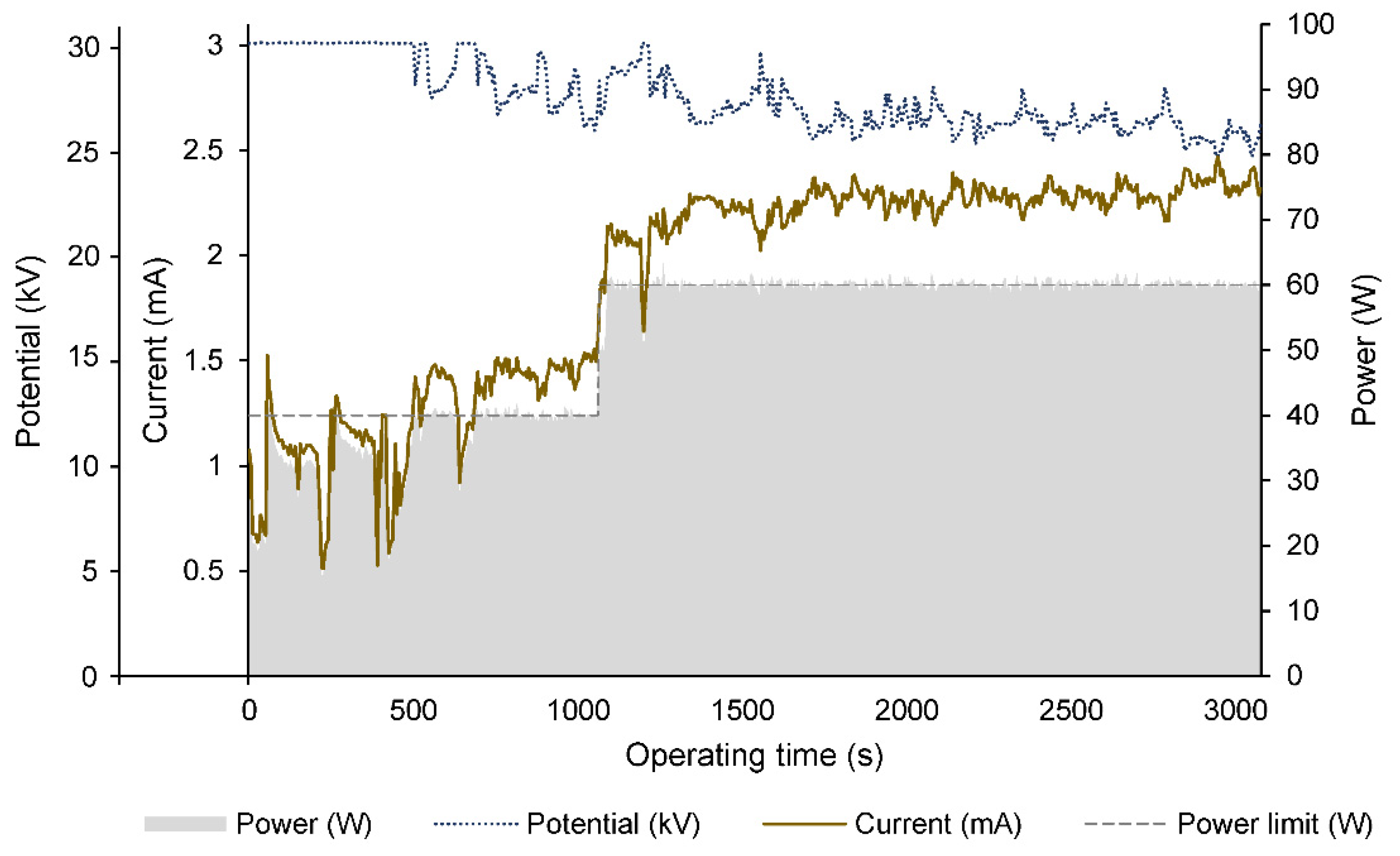
To perform a long-term test, the ESP needs to operate stably regardless of variations in flue gas. Biomass combustion is associated with fluctuations in emissions. Even when a steady state is reached, the PM emissions are not regular. Therefore, the operation of the ESP is also unstable. Sharp increases in particle concentration cause an increase in the current inside the ESP, which may reach 3 mA. At this point, the power supply unit stops working for safety reasons. These unintended shutdowns should be avoided in a long-term test; otherwise, the accumulation of operating time is interrupted and the results are not valid. Therefore, an electronic power control unit was designed to adjust the potential supplied based on the current readings. The control unit had an adjustable power limit and a target voltage. Under these conditions, when the current rises above the threshold value, the voltage is lowered to maintain constant power. The voltage is increased again when the current drops. The control and data acquisition were automated with an ARDUINO platform. This novel system successfully regulated the ESP operation parameters.
The dynamic control unit was tested under different conditions to ensure an appropriate regulation of the potential supplied to the discharge electrode according to the power limit and the current readings. The critical situation for this control unit is a continuous adjustment of the potential because of sharp variations of the current. This situation usually occurs when the conductivity of the electrical insulator that holds the discharge electrode increases. A common reason found in our tests was an inappropriate material for this application due to the lack of hydrophobic properties or an inadequate working temperature range. In these cases, the conductivity of the material increases with the operating time until the insulation effect is completely eliminated. The current raises continuously and the dynamic control unit should adjust the potential accordingly.
Figure 4 shows the results from a test of an ESP with a low-quality electrical insulator. First, the power is set to 40 W, and 15 min later, it is increased to 60 W. This change is also visible in the current, which indicates that the control unit is working properly. Moreover, the current continues to increase while the control unit decreases the potential, to maintain constant power. The target potential was set to 30 kV in this trial test, slightly above the previously selected 28 kV set for ordinary tests, to validate the electrical insulation. This test resulted in a failed electrical insulator. As a result, the current is higher than usual, and the target voltage is reached during a short time instead of being constant during the whole test. Nevertheless, it proved that the dynamic control unit worked as expected and that a long-period test could be performed regardless of emissions fluctuations.
The failed electrical insulators were replaced by optimized designs depending on the source of the failure. In this case, the material was not hydrophobic, thus vapor and particles were deposited on the surface and between the insulator and the discharge electrode. These depositions gradually increase the conductivity. To solve the problem, PTFE was successfully tested and chosen to be the insulator material.

3.3. Effect of the Operating Time on ESP Performance

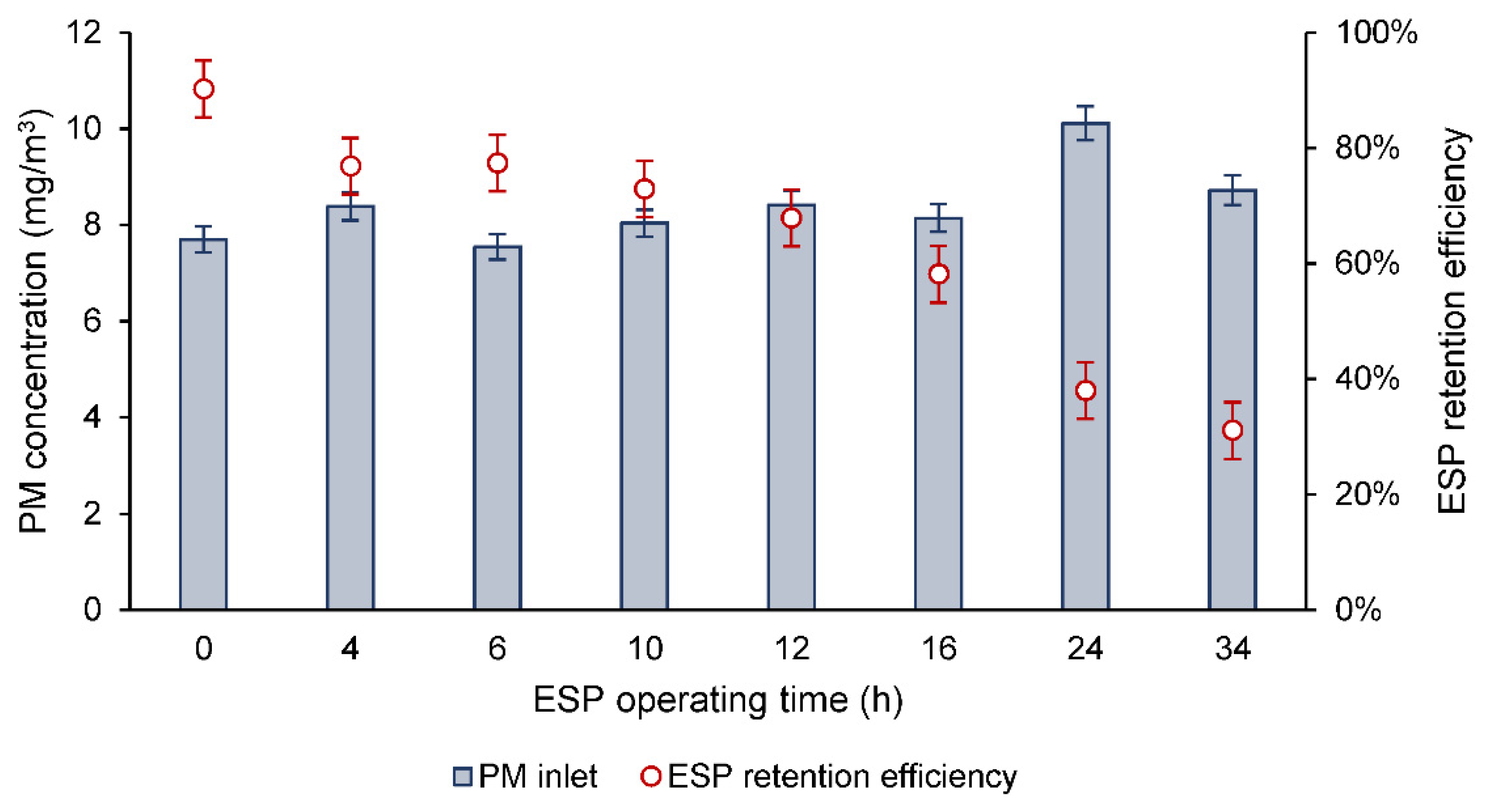
The ESP with setup C (Figure 3) was tested to analyze the effects of aging, and the results are shown in Figure 5. In this figure, the time evolution of the ESP retention efficiency with biomass combustion is provided. The test shows retention efficiency values below 40% after 30 h of operation with a pellet boiler. The average PM concentration at the inlet of the ESP is 8.4 mg/m3, referenced to 10% O2 and with an excess air ratio of 2. The retention efficiency is higher than 90% at the beginning of the test, when both electrodes are clean. Then, it is affected by the aging of the ESP. The accumulation of particles on both electrodes reduces the collection capacity of the precipitator with increasing operating time. Cleaning of the electrodes is necessary to recover the optimum performance of the device.
The figure also shows the PM concentration at the inlet of the ESP for each measurement of retention efficiency. It is important to compare efficiency values with similar references of PM since the retention capacity of the ESP decreases with sudden increases in particles. The PM concentration at the inlet of the ESP after 24 h of operation is slightly higher than the other values, but the difference is not enough to change the trend of the retention efficiency; thus, all the measurements are considered comparable.
The average uncertainty of the concentration measurements is 3.5% and the relative error associated with the retention efficiency values is ±4.9%.
The evolution of the retention efficiency is caused by changes in the electrical performance of the precipitator. Figure 6 shows the current–voltage curves of the ESP. The blue line corresponds to the clean ESP, the dotted line represents the results after 18 h of operation, and the dashed line represents the results after 33 h. These curves clearly indicate attenuation of the electric field strength due to the PM deposited on the surfaces of both discharge and collection electrodes. This effect on the VI curves has not been experimentally reported in previous studies to our knowledge.
The authors of [27] reported a reduction in retention efficiency of two ESPs with operating time. The results were linked to a reduction of active surfaces, which are covered by particles after some time of operation. Our results experimentally prove this hypothesis. An attenuation of the electric field inside the ESP is associated with the accumulation of particles on the active surfaces due to the operation of the ESP.

4. Conclusions

An experimental study was carried out with a laboratory-scale prototype ESP to reduce the PM emissions from a pellet boiler working at 25 kWth. High retention efficiencies were obtained with three different discharge electrode dispositions, regardless of their holding points, as long as they were protected from the gas flow path. The thinnest electrode showed the highest efficiency (98%) and the other thickness was used for two dispositions resulting in similar values (92%). Statements from other authors were verified with these results.
A novel dynamic control unit was developed to adjust the potential of the ESP under unstable gas conditions, preventing unintended shutdowns during operation. This unit was successfully evaluated and it regulated the ESP operation during a long-term test designed to analyze the aging effect. The ESP operated for 35 h despite the fluctuations of PM associated with biomass combustion. The ESP retention efficiency decreased as the particle layers continuously accumulated on both electrodes. The initial efficiency was 92% when the ESP was clean and the last registered value was 31% after 34 h of deposition of particles. The current–voltage curves showed that the attenuation of the electric field strength was also linked to the PM deposited inside the ESP. The electric field strength weakens with the operating time of the ESP, which represents a bigger quantity of particles on the surfaces of the electrodes. Periodic cleaning is needed to maintain optimum ESP performance and minimize particle emissions.

Author Contributions

Conceptualization, N.C. and A.L.; Data curation, A.L.; Funding acquisition, R.P.-O.; Investigation, N.C.; Methodology, N.C.; Project administration, J.J.R.; Resources, R.P.-O.; Supervision, R.P.-O.; Validation, N.C., J.J.R. and A.L.; Visualization, N.C.; Writing—Original draft, N.C.; Writing—Review and editing, J.J.R. All authors have read and agreed to the published version of the manuscript.

Funding

This research was funded by the Biomasa-AP project, which was approved by the INTERREG V-A España-Portugal 2014–2020 (POCTEP) and cofinanced by the European Regional Development Fund (FEDER). The work of Natalia Cid was supported by the Predoctoral Program Xunta de Galicia, grant number ED481A-2019/225. The work of Juan Jesús Rico was supported by a grant from the University of Vigo (P.P. 00VI 131H 6410211).

Acknowledgments

The authors would like to acknowledge financial support from the project Biomasa-AP, approved by the program INTERREG V-A España-Portugal 2014–2020 (POCTEP) and cofinanced by the European Regional Development Fund (FEDER). The work of Natalia Cid was supported by the Predoctoral Program Xunta de Galicia, grant number ED481A-2019/225. The work of Juan Jesús Rico was supported by a grant from the University of Vigo (P.P. 00VI 131H 6410211).

Conflicts of Interest

The author declares no conflict of interest.

References

  1. Rico, J.J.; Pérez-Orozco, R.; Cid, N.; Larrañaga, A.; Míguez Tabarés, J.L. Viability of Agricultural and Forestry Residues as Biomass Fuels in the Galicia-North Portugal Region: An Experimental Study. Sustainability 2020, 12, 8206. [Google Scholar] [CrossRef]
  2. Jesús Rico, J.; Patiño, D.; Cid, N.; Pérez-Orozco, R. PM reduction and flame confinement in biomass combustion using a porous inert material. Fuel 2020, 280, 118496. [Google Scholar] [CrossRef]
  3. Patiño, D.; Crespo, B.; Porteiro, J.; Villaravid, E.; Granada, E. Experimental study of a tubular-type ESP for small-scale biomass boilers: Preliminary results in a diesel engine. Powder Technol. 2016, 288, 164–175. [Google Scholar] [CrossRef]
  4. Betancourt Astete, R.; Gutiérrez-Cáceres, N.; Muñoz-Catalán, M.; Mora-Chandia, T. Direct Improvement in the Combustion Chamber and the Radiant Surface to Reduce the Emission of Particles in Biomass Cooking Stoves Used in Araucanía, Chile. Sustainability 2021, 13, 7205. [Google Scholar] [CrossRef]
  5. Pérez-Orozco, R.; Patiño, D.; Porteiro, J.; Míguez, J.L. Novel Test Bench for the Active Reduction of Biomass Particulate Matter Emissions. Sustainability 2020, 12, 422. [Google Scholar] [CrossRef] [Green Version]
  6. Kim, K.-H.; Kabir, E.; Kabir, S. A review on the human health impact of airborne particulate matter. Environ. Int. 2015, 74, 136–143. [Google Scholar] [CrossRef]
  7. Traboulsi, H.; Guerrina, N.; Iu, M.; Maysinger, D.; Ariya, P.; Baglole, C.J. Inhaled Pollutants: The Molecular Scene behind Respiratory and Systemic Diseases Associated with Ultrafine Particulate Matter. Int. J. Mol. Sci. 2017, 18, 243. [Google Scholar] [CrossRef] [PubMed]
  8. Pérez-Orozco, R.; Patiño, D.; Porteiro, J.; Rico, J.J. The effect of primary measures for controlling biomass bed temperature on PM emission through analysis of the generated residues. Fuel 2020, 280, 118702. [Google Scholar] [CrossRef]
  9. Patiño, D.; Moran, J.; Porteiro, J.; Collazo, J.; Granada, E.; Miguez, J.L. Improving the Cofiring Process of Wood Pellet and Refuse Derived Fuel in a Small-Scale Boiler Plant. Energy Fuels 2008, 22, 2121–2128. [Google Scholar] [CrossRef]
  10. Míguez, J.L.; Porteiro, J.; Behrendt, F.; Blanco, D.; Patiño, D.; Dieguez-Alonso, A. Review of the use of additives to mitigate operational problems associated with the combustion of biomass with high content in ash-forming species. Renew. Sustain. Energy Rev. 2021, 141, 110502. [Google Scholar] [CrossRef]
  11. Pérez-Orozco, R.; Patiño, D.; Porteiro, J.; Larrañaga, A. Flue Gas Recirculation during Biomass Combustion: Implications on PM Release. Energy Fuels 2020, 34, 11112. [Google Scholar] [CrossRef]
  12. Khodaei, H.; Guzzomi, F.; Patiño, D.; Rashidian, B.; Yeoh, G.H. Air staging strategies in biomass combustion-gaseous and particulate emission reduction potentials. Fuel Process. Technol. 2017, 157, 29–41. [Google Scholar] [CrossRef]
  13. Regueiro, A.; Patiño, D.; Porteiro, J.; Granada, E.; Míguez, J.L. Effect of Air Staging Ratios on the Burning Rate and Emissions in an Underfeed Fixed-Bed Biomass Combustor. Energies 2016, 9, 940. [Google Scholar] [CrossRef] [Green Version]
  14. Pérez-Orozco, R.; Patiño, D.; Porteiro, J.; Míguez, J.L. Bed cooling effects in solid particulate matter emissions during biomass combustion. A morphological insight. Energy 2020, 205, 118088. [Google Scholar] [CrossRef]
  15. Smith, W.J.; Morrin, S.; Timoney, D.J. Effect of operating condition on the particulate matter emission factor for a domestic biomass boiler. Proc. Inst. Mech. Eng. Part A J. Power Energy 2011, 225, 614–618. [Google Scholar] [CrossRef]
  16. Nugraha, M.G.; Saptoadi, H.; Hidayat, M.; Andersson, B.; Andersson, R. Particulate Matter Reduction in Residual Biomass Combustion. Energies 2021, 14, 3341. [Google Scholar] [CrossRef]
  17. Commission Regulation. Commission regulation (EU) 2015/1189 of 28 April 2015 implementing Directive 2009/125/EC of the European Parliament and of the Council with regard to ecodesign requirements for solid fuel boilers. Off. J. Eur. Union 2015, 19, 3–5. [Google Scholar]
  18. Singh, R.; Shukla, A. A review on methods of flue gas cleaning from combustion of biomass. Renew. Sustain. Energy Rev. 2014, 29, 854–864. [Google Scholar] [CrossRef]
  19. Sippula, O.; Hokkinen, J.; Puustinen, H.; Yli-Pirilä, P.; Jokiniemi, J. Particle Emissions from Small Wood-fired District Heating Units. Energy Fuels 2009, 23, 2974–2982. [Google Scholar] [CrossRef]
  20. Intra, P.; Limueadphai, P.; Tippayawong, N. Particulate emission reduction from biomass burning in small combustion systems with a multiple tubular electrostatic precipitator. Part. Sci. Technol. 2010, 28, 547–565. [Google Scholar] [CrossRef]
  21. Lim, M.T.; Phan, A.; Roddy, D.; Harvey, A. Technologies for measurement and mitigation of particulate emissions from domestic combustion of biomass: A review. Renew. Sustain. Energy Rev. 2015, 49, 574–584. [Google Scholar] [CrossRef]
  22. Poškas, R.; Sirvydas, A.; Poškas, P.; Šimonis, V.; Jankauskas, J. Investigation of the ESP cleaning efficiency of the flue gases in the wide range of Re numbers. Mechanika 2017, 23, 47–54. [Google Scholar] [CrossRef] [Green Version]
  23. Bologa, A.; Paur, H.R.; Ulbricht, T.; Woletz, K. Particle emissions from small scale wood combustion devices and their control by electrostatic precipitation. Chem. Eng. Trans. 2010, 22, 119–124. [Google Scholar] [CrossRef]
  24. Kim, H.-J.; Han, B.; Kim, Y.-J.; Yoa, S.-J. Characteristics of an electrostatic precipitator for submicron particles using non-metallic electrodes and collection plates. J. Aerosol Sci. 2010, 41, 987–997. [Google Scholar] [CrossRef]
  25. Ni, M.; Wang, X.; Xiao, G.; Qiu, K.; Yang, G.; Gao, X.; Cen, K. Development of back corona discharge in a wire-cylinder electrostatic precipitator at high temperatures. Powder Technol. 2015, 286, 789–797. [Google Scholar] [CrossRef]
  26. Chang, C.-L.; Bai, H. An experimental study on the performance of a single discharge wire-plate electrostatic precipitator with back corona. J. Aerosol Sci. 1999, 30, 325–340. [Google Scholar] [CrossRef]
  27. Migliavacca, G.; Morreale, C.; Hugony, F.; Tombolato, I.; Pession, G. Reduction of pm emissions from biomass combustion appliances: Evaluation of efficiency of electrostatic precipitators. Chem. Eng. Trans. 2014, 37, 25–30. [Google Scholar] [CrossRef]
  28. Brunner, T.; Wuercher, G.; Obernberger, I. 2-Year field operation monitoring of electrostatic precipitators for residential wood heating systems. Biomass Bioenergy 2018, 111, 278–287. [Google Scholar] [CrossRef]
  29. Carroll, J.; Finnan, J. Use of electrostatic precipitators in small-scale biomass furnaces to reduce particulate emissions from a range of feedstocks. Biosyst. Eng. 2017, 163, 94–102. [Google Scholar] [CrossRef]
  30. Oischinger, J.; Steiner, M.; Meiller, M.; Hebauer, M.; Beer, S.; Daschner, R.; Hornung, A.; Kramb, J. Optimization of the fractional collection efficiencies for electrostatic precipitators used in biomass-fired boilers. Biomass Bioenergy 2020, 141, 105703. [Google Scholar] [CrossRef]
  31. Schmatloch, V.; Rauch, S. Design and characterisation of an electrostatic precipitator for small heating appliances. J. Electrostat. 2005, 63, 85–100. [Google Scholar] [CrossRef]
  32. Fischer, T.; Graß, N.; Zouzou, N.; Dascalescu, L.; Greil, R.; Hopf, N. Smart home precipitator for biomass furnaces: Design considerations on a small-scale electrostatic precipitator. IEEE Trans. Ind. Appl. 2014, 50, 2219–2224. [Google Scholar] [CrossRef]
  33. Jaworek, A.; Sobczyk, A.T.; Marchewicz, A.; Krupa, A.; Czech, T. Particulate matter emission control from small residential boilers after biomass combustion. A review. Renew. Sustain. Energy Rev. 2021, 137, 110446. [Google Scholar] [CrossRef]
  34. Crespo, B.; Patiño, D.; Regueiro, A.; Granada, E. Performance of a lab-scale tubular-type electrostatic precipitator using a diesel engine particle emission source. Energy 2016, 116, 1444–1453. [Google Scholar] [CrossRef]
  35. Garcia-Maraver, A.; Zamorano, M.; Fernandes, U.; Rabaçal, M.; Costa, M. Relationship between fuel quality and gaseous and particulate matter emissions in a domestic pellet-fired boiler. Fuel 2014, 119, 141–152. [Google Scholar] [CrossRef]
  36. Verma, V.K.; Bram, S.; Vandendael, I.; Laha, P.; Hubin, A.; De Ruyck, J. Residential pellet boilers in Belgium: Standard laboratory and real life performance with respect to European standard and quality labels. Appl. Energy 2011, 88, 2628–2634. [Google Scholar] [CrossRef]
  37. Andrade, R.G.S.A.; Guerra, V.G. Discharge electrode influence on electrostatic precipitation of nanoparticles. Powder Technol. 2021, 379, 417–427. [Google Scholar] [CrossRef]
Figure 1. Diagram of the system.
Sustainability 13 10344 g001
Figure 2. Particle size distribution of the gas from the biomass boiler.
Sustainability 13 10344 g002
Figure 3. Laboratory-scale ESPs with three (AC) different discharge electrode dispositions.
Sustainability 13 10344 g003
Figure 4. Regulation of the dynamic control unit.
Sustainability 13 10344 g004
Figure 5. Evolution of ESP retention efficiency during operation.
Sustainability 13 10344 g005
Figure 6. Evolution of the current–voltage curve during the operation of the ESP.
Sustainability 13 10344 g006
Table 1. Pellets proximate analysis.
Wet BasisDry BasisDry Basis without Ashes
Humidity (%)6.416.856.89
Volatile compounds (%)68.8073.5173.95
Fixed carbon (%)24.2325.8926.05
Ashes (%)0.570.600.61
Table 2. Pellets ultimate analysis.
Wet BasisDry BasisDry Basis without Ashes
C (%)44.8547.9248.24
N (%)0.240.260.26
H (%)6.456.896.94
S (%)0.00 10.00 10.00 1
Humidity (%)6.410.000.00
Ashes (%)0.570.600.00
O (%)41.4844.3244.56
1 Under detection level.
Table 3. Ash analysis.
ElementElement in Dry Pellet (mg/kg)Element in Dry Pellet (%)
Na160.000.02
Mg366.670.04
Al270.000.03
Si586.670.06
P116.670.01
S286.670.03
Cl240.000.02
K1236.670.12
Ca1223.330.12
Ti17.330.00
Mn61.330.01
Fe112.000.01
Zn10.000.00
Ba33.000.00
Total4270.330.47
Publisher’s Note: MDPI stays neutral with regard to jurisdictional claims in published maps and institutional affiliations.