Article

Model Predictive Control of the Input Current and Output Voltage of a Matrix Converter as a Ground Power Unit for Airplane Servicing

1
School of Electrical and Electronic Engineering, The University of Adelaide, Adelaide, SA 5005, Australia
2
School of Electrical and Data Engineering, University of Technology Sydney, Sydney, NSW 2007, Australia
3
School of Electrical and Information Engineering, The University of Sydney, Sydney, NSW 2006, Australia
4
Facultad de Ingeniería, Universidad de Talca, Curico 3341717, Chile
5
School of Electrical Engineering, University of Belgrade, 11000 Belgrade, Serbia
*
Author to whom correspondence should be addressed.
Sustainability 2021, 13(17), 9715; https://doi.org/10.3390/su13179715
Submission received: 3 July 2021 / Revised: 17 August 2021 / Accepted: 25 August 2021 / Published: 30 August 2021
(This article belongs to the Special Issue Renewable Energy Technologies for Sustainable Development)

Abstract

:
This paper deals with the design, control, and implementation of a three-phase ac–ac mobile utility power supply using a matrix converter for airplane servicing applications. Using a matrix converter as a compact direct ac-to-ac converter can provide savings in terms of the size and cost of a mobile power supply compared to common back-to-back converters. Furthermore, using the proposed direct matrix converter eliminates the need for bulky electrolytic capacitors and increases the system’s reliability and lifetime. A finite control set model predictive control is used to generate a high-quality 115 V/400 Hz output voltage and a low-harmonic-distortion source current with a unity input power factor for various load conditions, including balanced, unbalanced, linear, and nonlinear loads. The predictive strategy is used to control the output voltage and source current for each possible switching state in order to simultaneously track the references. To achieve a further reduction in the system’s size and cost, an active damping strategy is used to compensate for the instability caused by the input filter in contrast to the passive method. Experimental tests were conducted on a prototype matrix converter to validate the performance of the proposed control strategy.

1. Introduction

In recent years, power-electronics-based power supplies coupled with an output LC filter have been proposed for different applications. In aircraft applications, ground power units (GPUs) provide balanced and sinusoidal phase-to-neutral voltages of 115 Vrms at a frequency of 400 Hz to supply airplanes with external electrical power during stopovers in airports. Because of the low ratio between the switching frequency of the converter and the fundamental output frequency (400 Hz), only some special control methods can achieve the requirements of the GPUs.
Back-to-back converters have been conventionally used to provide power as GPUs for aircraft, where a dc filter reduces the current ripple of the rectifier and supplies the inverter. However, using electrolytic capacitors as filter components increases the size and cost of the converter and reduces the system’s reliability. The problem is more considerable in high-power, high-voltage applications due to the rating limits of the components. The control of inverters with an output LC filter can achieve good voltage regulation with different kinds of loads [1,2,3]. Instead of back-to-back converters, matrix converters (MCs) can be utilized as a compact solution without a DC capacitor [4,5,6] as very-high-performance GPUs for aircraft applications.
For this purpose, some MC-based control methods have been proposed for power supply units, some of which are especially for aircraft applications. The simple d-q reference frame approach and the approach of optimizing control design method by using a genetic algorithm, which were proposed in [7,8,9], cannot meet the requirements in the common case of an unbalanced load. In addition, the optimized control system in the ABC frame presented in [10,11], which employs a repetitive controller, shows good output voltage control performance for balanced and unbalanced loads. However, the source current is not directly controlled and has a low quality.
The other control strategy is the model predictive control (MPC), which has been applied to inverters and MCs for power supply applications [12,13,14,15,16]. However, employing MPC to control a 400 Hz GPU still remains a challenge due to the insufficient ratio between the switching frequency and the output frequency, as well as the instability caused by the input filter. If the input filter is not carefully damped, the oscillation of the input current can generate significant distortion in the output voltage, thus deteriorating the system’s control performance [17,18]. Hence, in addition to the careful design of the control, a suitable damping method is needed in order to meet the performance requirements and to reduce the transient oscillations at power-up and the instant of load disconnection [19,20,21,22].
As an example, in [14,15,16], the finite control set model predictive control (FCS-MPC) was successfully used to control the output voltage with a unity input power factor (PF). However, the source current was not fully controlled, and the resultant source currents were distorted. Controlling the source and load currents using the MPC was proposed in [23] for an indirect MC. In fact, none of the mentioned MC control strategies are able to control the quality of the source current and output voltage at the same time, though this problem is dealt with in this paper.
This paper presents the design of an FCS-MPC for a three-phase GPU based on a direct matrix converter. The main objective of the paper is to propose an ac–ac converter for mobile power supplies with a smaller size, lower cost, and more reliability due to their importance in the aviation industry. Simultaneous control of the output voltage and input current with low harmonic distortion and a unity input PF is achieved for all load conditions—namely, balanced, unbalanced, linear, and nonlinear conditions. The fast, transient behavior of the converter under the no-load condition is also investigated. Furthermore, an active damping strategy is suggested for the stabilization of the converter in the presence of LC filters with a smaller power dissipation compared to the passive dampers. To reduce the number of current sensors required, a load-current observer is used to estimate the load currents. Experimental results are presented to validate the performance of the proposed control technique and damping strategy. In Section 2, the stability problem of the converter related to the LC filter and an active damping method as a solution will be explained. A detailed analysis of the proposed control scheme and an analysis of the load-current observer are presented in Section 3, and then the experimental results are discussed in Section 4. Finally, Section 5 draws the conclusions of the work.

2. System Stabilization

LC filters are generally used at the input and output of MCs and are essential for switching ripple attenuation. The design and component selection of the filters must be such that they not only do not degrade the current and voltage regulation, but they also have the least impact on the system’s efficiency and reactive power [24]. The design of the input and output filters has been discussed in different works in the literature [25,26,27]. The filter inductance L f must be selected so as to cause a minimum voltage drop at the input current rated for gaining the maximum voltage ratio, and the output filter’s inductance should not be too large due to the transient dynamics, particularly for sudden interruptions of the load.
The input LC filter can significantly impact the stability of the converter when the output variables of the converter are tightly regulated. In this case, the converter behaves as a constant power load and presents a negative incremental input resistance, which can destabilize the converter depending on the system parameters [17,18]. To stabilize the converter, active and passive damping methods can be utilized as a solution. However, any instability caused by the filters must be compensated with a minimum power loss while maintaining the desired voltage and current total harmonic distortion (THD).
A common method for overcoming the instability caused by the input filter is that of adding a damping resistor in parallel with the filter inductor in order to compensate the incremental negative resistance of the MC [19,28]. The damping factor of the LC filter is normally small due to the negligible value of the inductor resistance ( R f ), which can be increased by adding damping resistors. Although a small damping resistance can increase the damping properties of the filter, it not only raises the power loss, but also transfers high-frequency distortion to the input side, which leads to a higher THD for the source current [29]. In order to reduce the power loss, this paper suggests an active damping method as an alternative.
The active damping technique acts as a virtual resistor in order to mitigate the resonance effect of the LC filters by modifying the controller and, thus, overcoming the problem of instability caused by tightly regulated converters [30,31]. As an advantage, the method has no extra cost or power loss because it is implemented in the form of software. Different active damping methods have been introduced in the literature, such as stabilization using a digital filter [22,32], where a digital low-pass filter filters out the measured input voltage. However, there is a possibility for input voltage disturbances to be reflected in the output voltage proportionally to the filter’s time constant [33,34,35]. Furthermore, there is a possibility of transient oscillations at the time of a step-change in power. Another method is based on the active harmonic damping algorithm, and it involves the construction of a correction term in order to increase the input impedance of the MC [36]. In the case of MPC, an active damping method was introduced in [20]; the output current reference was modified by the extracted harmonics of the input voltage. Here, an active damping method was applied to modify the output reference voltage. The power circuit of the converter and the control scheme are shown in Figure 1.
As illustrated in Figure 1, the d-q parts of the source current ( i s ) are filtered by digital high-pass filters to extract the harmonic components. These values are multiplied by a coefficient ( k d ) and added to the d-q components of the output reference voltage, v f ( d ) r and v f ( q ) r , to obtain the new output reference voltage ( v ˜ f r ). In this way, the fundamental element of the source current is not affected by the active damping, while the harmonics are compensated by the new reference output voltage.

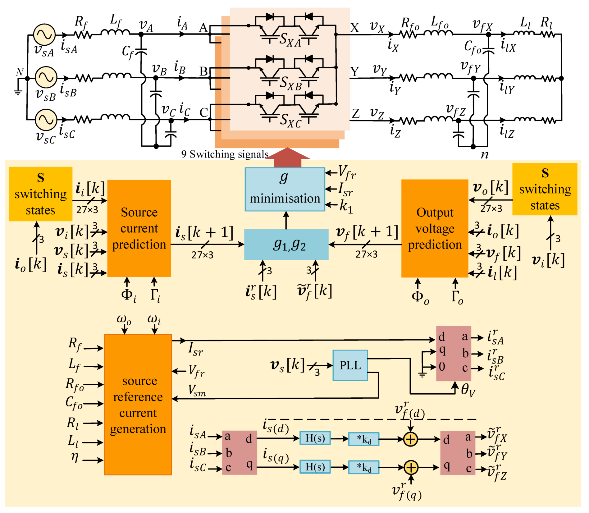
3. Proposed Control Scheme

In an FCS-MPC, several system variables can be controlled with a single control function by using appropriate weighting factors [37,38,39]. As an example, in [23], the source and load currents were fully controlled. In addition, the output voltage of the MC was controlled in [14,15,16] with a unity input PF. In this paper, this strategy was investigated in order to control the output voltage of the direct matrix converter (DMC) and, at the same time, the source current in order to obtain a low-distortion current with a unity input PF.

3.1. Input Current Control

To achieve a three-phase sinusoidal source current with low distortion and a unity PF, the input current needs to be controlled by defining the source reference current. The amplitude of the source reference current ( I s r ) can be found as a function of the amplitude of the output reference voltage V f r and the converter efficiency ( η ), as illustrated in Figure 1 for an RL load. The equality of the input and output active powers of the converter, considering the system efficiency, is as follows:
P o = η P i
Considering Figure 1, the input voltages of the source ( v s ) and the converter ( v i ), as well as the currents of the source ( i s ) and the converter ( i i ), are defined as:
v s = v s A v s B v s C , v i = v A v B v C , i s = i s A i s B i s C , i i = i A i B i C
For each phase, the input active power P i can be obtained from the real part of the input complex power as follows:
S i = V i I i *
where the input voltage and current V i and I i are defined as:
V i = V s I s Z 1 I i = Z c + Z 1 Z c I s 1 Z c V s
and
Z 1 = R f + j L f ω i Z c = 1 j ω i C f
where ω i is the input angular frequency, L f includes the inductances of the line and input filter, and R f is the sum of the resistances of the line and L f . V s and I s , as the source voltage and current phasors, are defined using:
V s = V s m e j θ V , I s = I s r e j θ I
where V s m is the amplitude of the source voltage and I s r is the source reference current amplitude, and θ V and θ I are their angles, respectively. Considering the unity input PF ( θ V θ I = 0 ), the input active power is:
P i = R e { S i } = V s m I s r R f I s r 2
In the same way, the voltages and currents on the output side are:
v o = v X v Y v Z , v f = v f X v f Y v f Z , i o = i X i Y i Z , i l = i l X i l Y i l Z
and the complex power for each output phase is determined as:
S o = V o I o *
where
V o = I o ( R f o + j L f o ω o ) + V f
I o = V f Z 2
Z 2 = ( 1 j C f o ω o ) ( R l + j L l ω o )
ω o represents the output angular frequency, L f o and C f o represent the output filter elements, R f o represents the resistance of the output filter inductor, and L l and R l represent the load parameters. Therefore, considering the output voltage reference amplitude of V f r , the active power of each output phase can be defined as:
P o = R e { S o } = V f r 2 x c 2 R f o + R f o + R l 2 R f o x l x c R l 2 + x l 2
x c = C f o ω o , x l = L l ω o
The source reference current amplitude ( I s r ) can then be obtained using (1), (7), and (13) as:
R f I s r 2 V s m I s r + P o / η = 0
I s r = V s m V s m 2 4 R f P o / η 2 R f
Figure 2 illustrates the changes in the amplitude of the source reference current ( I s r ) as a function of the load resistance and the source voltage amplitude ( V s m ), and two different values of source voltage have been highlighted in the graph.
In order to find the predictive equations of the source current, the modeling equations at the input side of the MC can be developed as follows:
d v i ( t ) d t d i s ( t ) d t = A i v i ( t ) i s ( t ) + B i v s ( t ) i i ( t )
where the matrix coefficients are defined as:
A i = 0 1 C f 1 L f R f L f , B i = 0 1 C f 1 L f 0
The control algorithm is applied to each sampling instant k. To find a simple expression for predicting the behavior of the system, an approximation of the derivatives for each variable ( x ) can be considered for sampling time T s p as follows:
d x d t x [ k + 1 ] x [ k ] T s p
In this way, the corresponding discrete-time model of the input side can be determined:
v i [ k + 1 ] i s [ k + 1 ] = Φ i v i [ k ] i s [ k ] + Γ i v s [ k ] i i [ k ]
Φ i = e A i T s p , Γ i = A i 1 ( Φ i I ) B i
where I is a 2 × 2 identity matrix. Therefore, the predictive equation of the source current is finally defined as:
i s [ k + 1 ] = Φ i ( 2 , 1 ) v i [ k ] + Φ i ( 2 , 2 ) i s [ k ] + Γ i ( 2 , 1 ) v s [ k ] + Φ i ( 2 , 2 ) i i [ k ]
where i i [ k ] is obtained from i o [ k ] for all 27 valid switching states.

3.2. Modeling and Control of the Output Voltage

The modeling equations for the output side can be developed (referring to Figure 1) as following:
C f o d v f d t = i o i l d i o d t = 1 L f o ( v o v f R f o i o ) d i l d t = 1 L l v f R l L l i l
The equations can be rewritten in matrix form as:
d v f ( t ) d t d i o ( t ) d t = A o v f ( t ) i o ( t ) + B o v o ( t ) i l ( t )
where the matrix coefficients are defined as:
A o = 0 1 C f o 1 L f o R f o L f o , B o = 0 1 C f o 1 L f o 0
The corresponding discrete-time model of the output side can then be determined as follows:
v f [ k + 1 ] i o [ k + 1 ] = Φ o v f [ k ] i o [ k ] + Γ o v o [ k ] i l [ k ]
Φ o = e A o T s p , Γ o = A o 1 ( Φ o I ) B o
Therefore, the following predictive equation of the output voltage is obtained:
v f [ k + 1 ] = Φ o ( 1 , 1 ) v f [ k ] + Φ o ( 1 , 2 ) i o [ k ] + Γ o ( 1 , 1 ) v o [ k ] + Γ o ( 1 , 2 ) i l [ k ]
The output voltage v o [ k ] is a dependent variable of the switching states and the input voltage, and it can be determined for each of the 27 valid switching states ( v o [ k ] = S . v i [ k ] ).
The cost function for the regulation of the output voltage can be defined as:
g 1 = v ˜ f X r [ k ] v f X [ k + 1 ] 2 + v ˜ f Y r [ k ] v f Y [ k + 1 ] 2 + v ˜ f Z r [ k ] v f Z [ k + 1 ] 2
and at the source side, it can be defined as:
g 2 = i s A r [ k ] i s A [ k + 1 ] 2 + i s B r [ k ] i s B [ k + 1 ] 2 + i s C r [ k ] i s C [ k + 1 ] 2
where i s r and v f r are the source current and output voltage references, and v ˜ f r is the modified output reference voltage for active damping, as illustrated below:
i s r = i s A r i s B r i s C r , v f r = v f X r v f Y r v f Z r , v ˜ f r = v ˜ f X r v ˜ f Y r v ˜ f Z r
Using (29) and (30), the output voltages and source currents can be controlled at the same time; both are sinusoidal and of a good quality. Furthermore, the input displacement angle remains zero for any output voltage amplitude. The final cost function used for the minimization algorithm consists of the following cost functions of g 1 and g 2 [40]:
g = g 1 + k 1 g 2
where k 1 is a weighting factor that is selected in such a way that the standard quality of both variables is satisfied. The cost function is evaluated for each sampling time considering all 27 switching states. Finally, the switching state associated with the prediction that generates the minimum cost function is chosen for the following time interval.

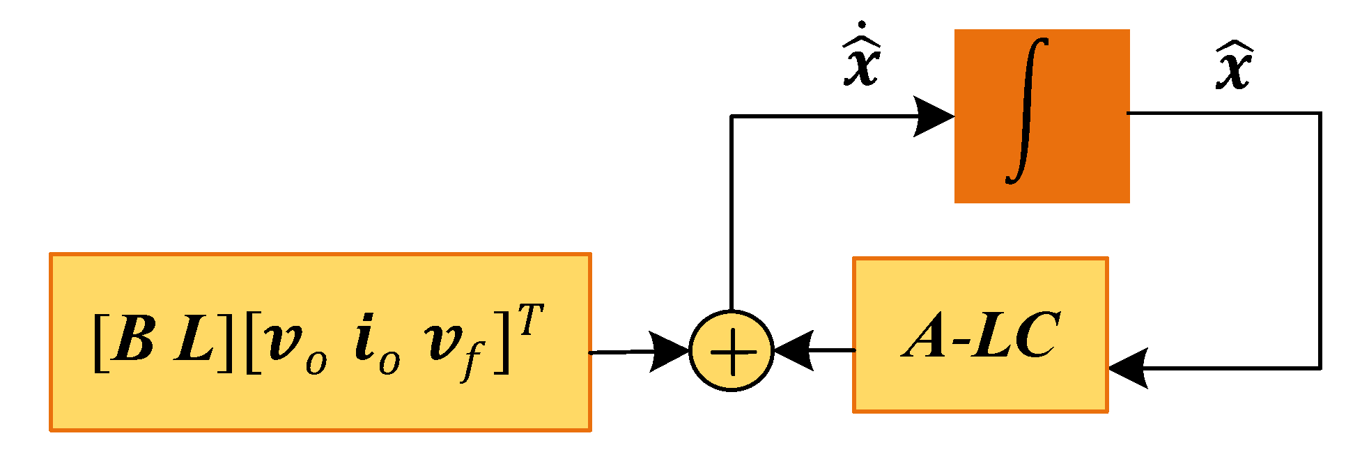
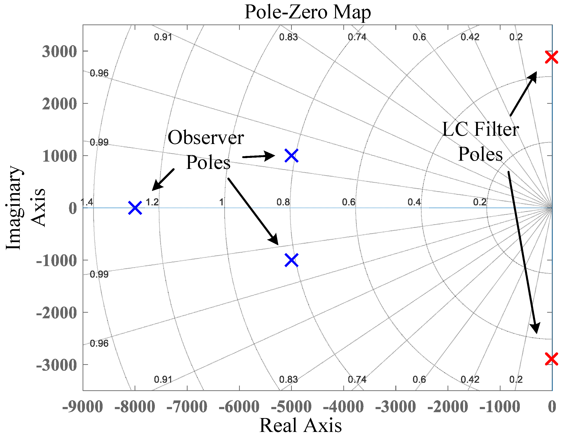
3.3. Load-Current Observer

As can be seen in (28), the load current i l [ k ] is necessary for the prediction of the output voltage ( v f ). The load currents can be estimated in order to avoid the use of extra sensors and increasing the cost of the system. As the load-current dynamic is slow enough compared to the sampling time, an observer can be used to estimate these currents. Therefore, during a sampling period, the load current is approximated as a constant ( d i l / d t = 0 ). The state-space model of the input and the measured output are defined as follows [12,14]:
x ˙ = Ax + Bu
y = Cx
x = i o v f i l T
u = v o
where x is the state vector, u is the output voltage vector, as presented in (8), and A , B , and C are:
A =   R f o L f o 1 L f o 0 L f o C f o L f o 0 1 C f o 0 0 0 , B =   1 L f o 0 0 , C =   1 0 0 0 1 0
A closed-loop observer continually compensates for any errors in the estimate by using the output equation. The error signal that is used to compensate for the estimator is obtained as follows:
y y ^ = y C x ^
x ^ = i ^ o v ^ f i ^ l T
where the symbol “ ^ ” denotes the estimated variable. The closed-loop estimator dynamic is [12]:
x ^ ˙ = A x ^ + Bu + L ( y y ^ ) = ( A LC ) x ^ + [ B L ] [ v o i o v f ] T
Matrix L 3 × 2 is the observer’s gain and is chosen by using the “place” function in Matlab with MC parameters to place the observer closed-loop poles at the desired locations. Figure 3 shows a block diagram of the observer using a discrete integrator, in which the third element is the load current estimation ( i l ^ ). In this work, the poles of the observer are chosen to be:
P = 1 e 4 [ 0.5 0.1 j , 0.5 + 0.1 j , 0.8 ]
L = p l a c e ( A , C , P )
where there is a tradeoff between bandwidth and noise rejection. Figure 4 presents a plot of the pole placement for the observer.

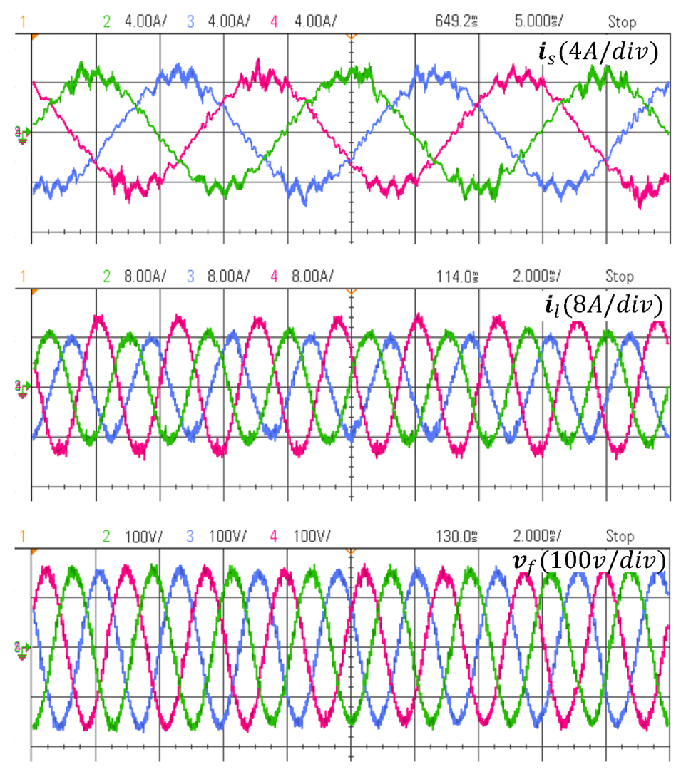
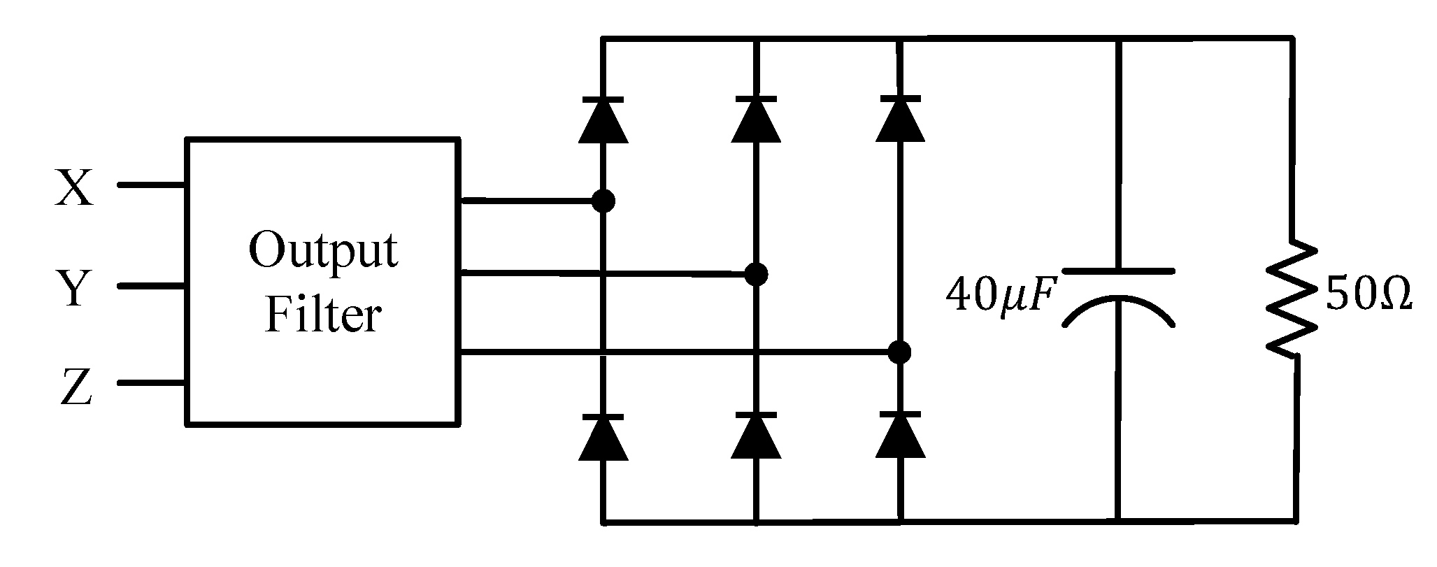
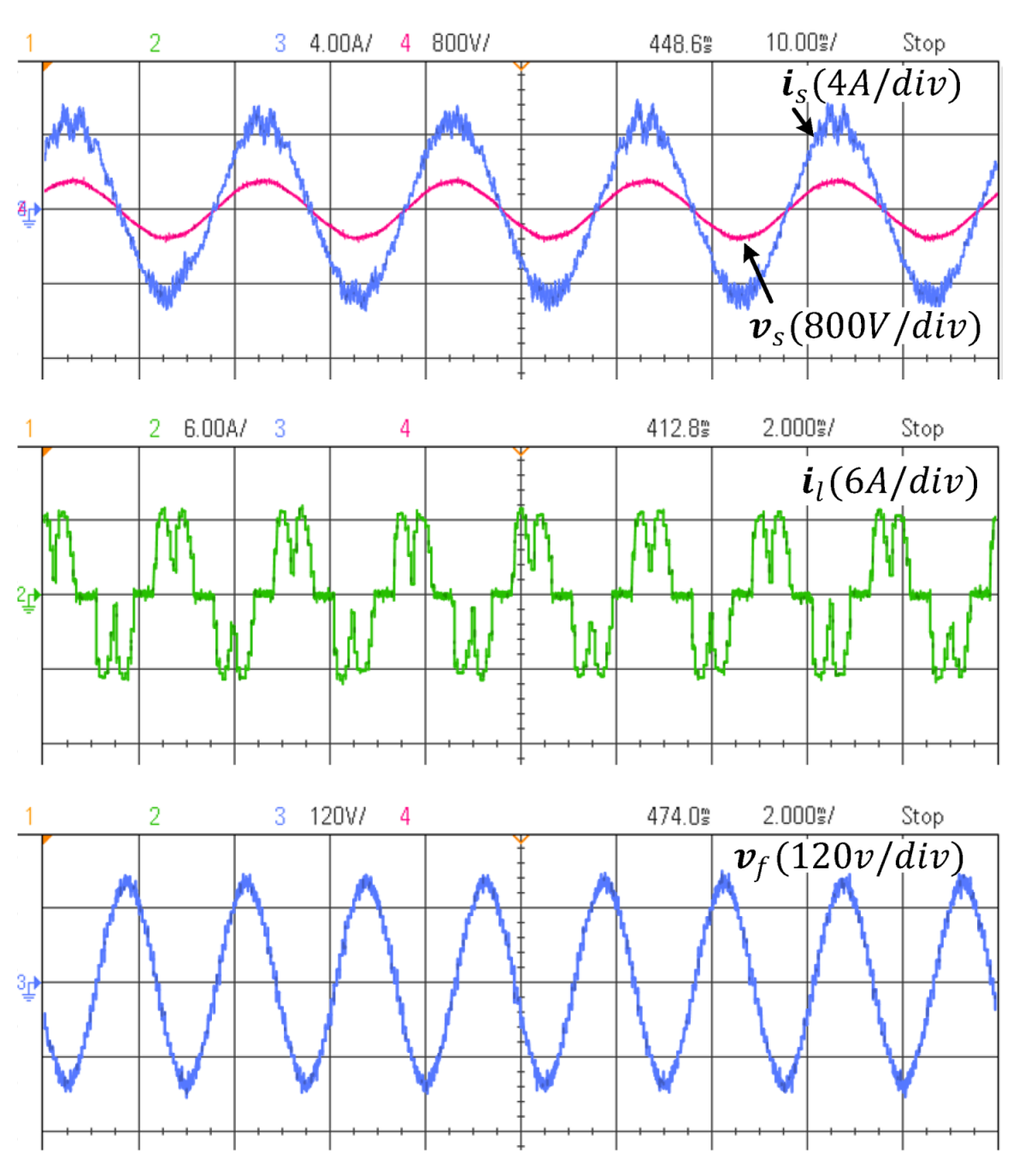
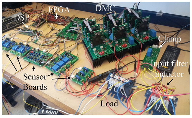
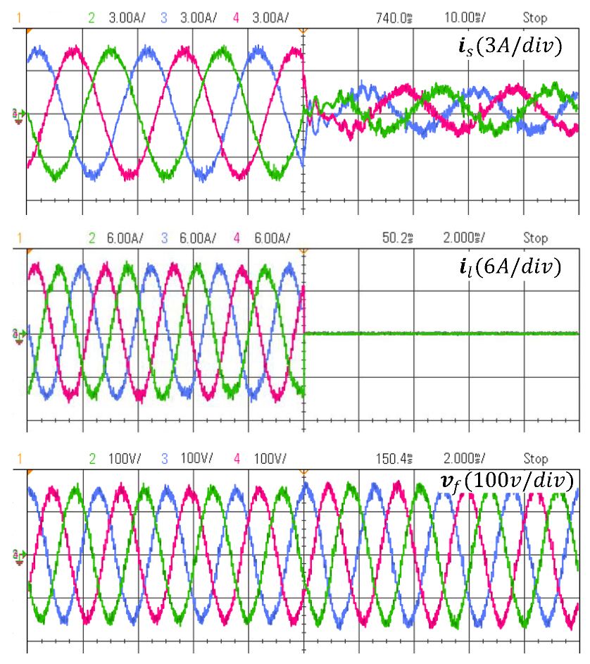
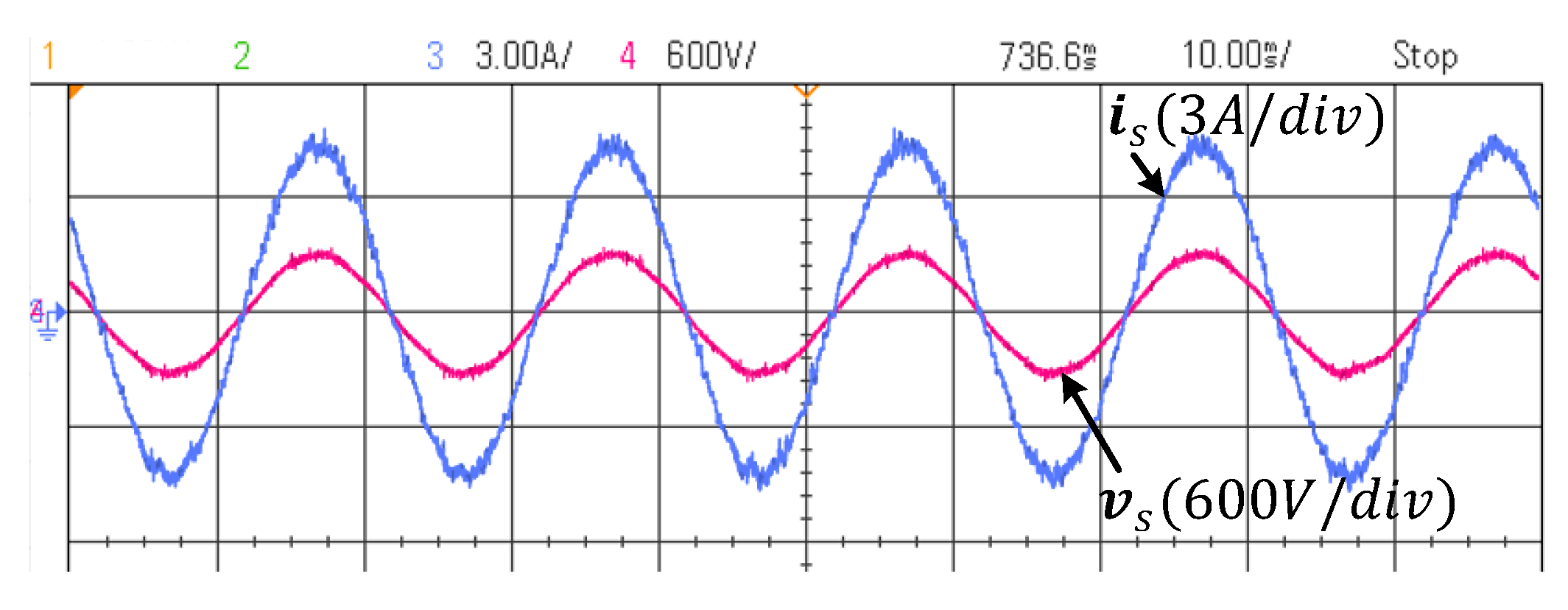
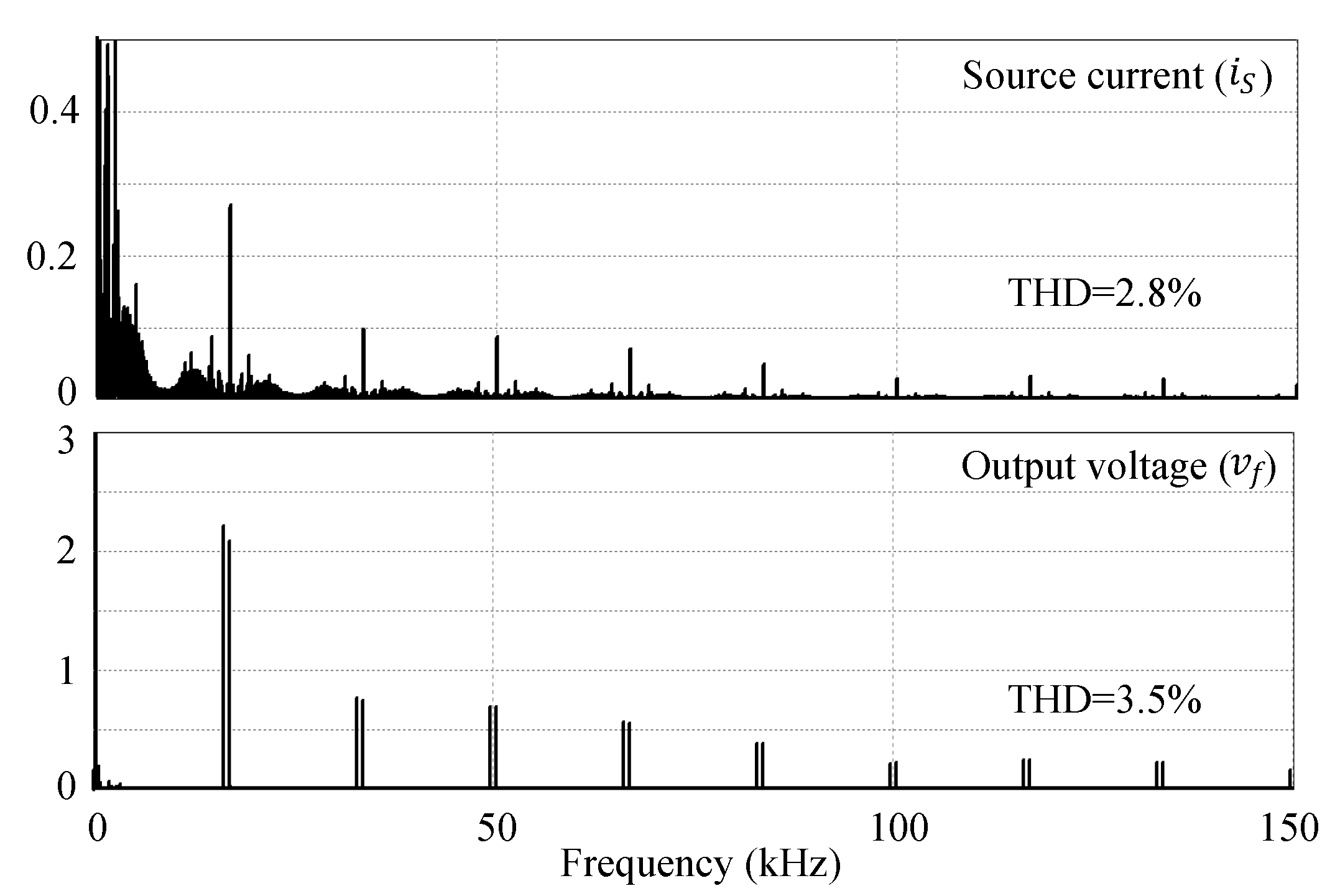
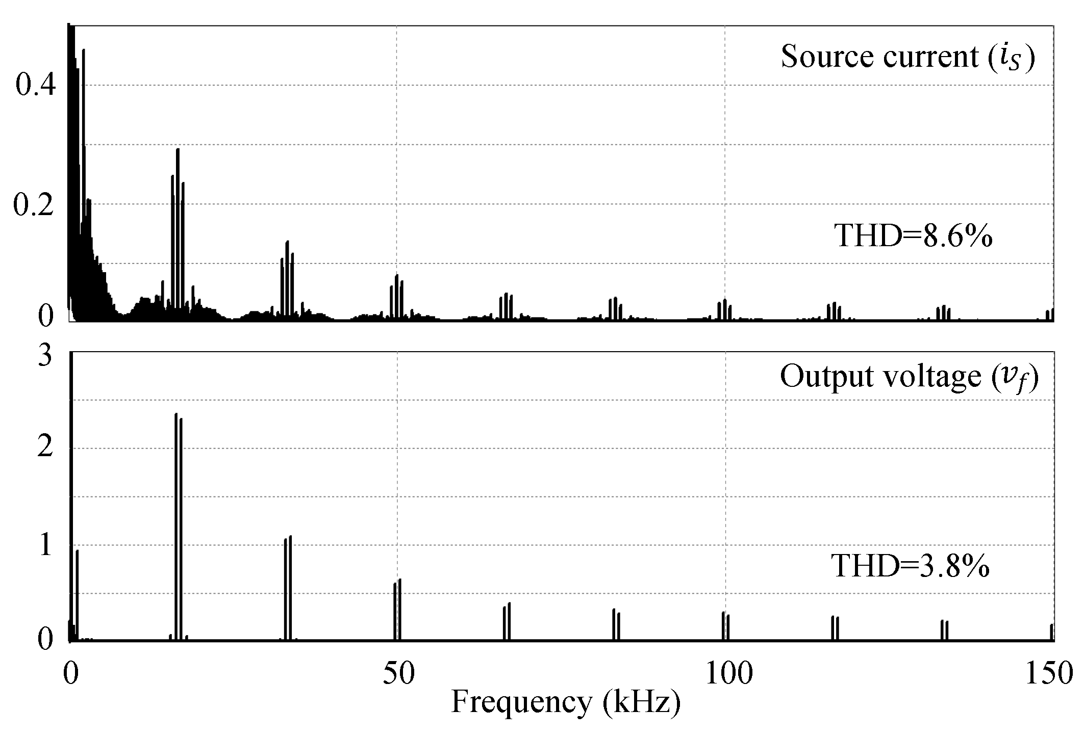
4. Experimental Results

The proposed predictive control strategy was tested experimentally using the prototype DMC presented in Figure 5. The converter consisted of an arrangement of 18 IGBT switches (IRG7PH42UD1-EP) with built-in antiparallel diodes in the bidirectional common-collector configuration. The driving signals were generated by two-channel hybrid integrated driver circuits (VLA567-01R) with built-in short-circuit protection. LEM sensors (LTSR 25-NP and LV 25-P) were used to measure the currents and voltages, respectively. The control schemes were implemented in C code by using a digital signal processor (DSP; model TMS320F28335), and a field-programmable gate array (FPGA) on a Xilinx Spartan6LX150T development board was programmed in VHDL to realize a four-step current-based commutation process [41]. To protect the converter from over-voltages caused by the forced shutdown of the converter or any other unpredictable disturbances, a clamp circuit was utilized; this included two fast-recovery diode bridges, a capacitor of 3.2   μ F, and a resistor of 50 k Ω . A DSOX2004A Keysight oscilloscope was utilized to record the waveforms. More details about the technical points of the design, control, stability analysis, and hardware development of the MC were presented in [4].
The system parameters are presented in Table 1 for an inductive–resistive load. Experimental results that show the steady-state performance with and without loads are presented. In addition, the transient behavior was investigated in the case of load disconnection. It was shown that the output voltage waveform met the target specifications with balanced or unbalanced loads. Different values of T s p were tested in the simulation, and the number of switching instants per second, which were counted with incremental counters, were compared in order to select the proper switching frequency for the proposed control method. For the output frequency of 400 Hz, the average switching frequency needed to be increased to about 15–17 kHz, which could be achieved with T s p = 60 μ s, and this resulted in an average switching frequency of about 16.6 kHz.
Figure 6 shows the steady-state and transient performance of the MC loaded with a balanced RL load when the load was disconnected. As can be seen, the source current and output voltage followed their references with a low distortion and THD of about 2.8% and 3.5%, respectively. In addition, the transient response of v f to the load disconnection was fast, and the controlled output voltage maintained its value without a noticeable change. Furthermore, the unity input PF was achieved, as shown in Figure 7. The results of an FFT analysis and the harmonic spectra for the source current and output voltage in Figure 8 show that the harmonics were in the range of the switching frequency and its multiples.
A balanced three-phase output voltage and source current could be achieved in the case of the unbalanced load with 140%, 100%, and 60% of the previous values for phases X, Y, and Z, respectively, as shown in Figure 9. The applied load resistances were 16.8 Ω , 12 Ω , and 7.2 Ω for phases X, Y, and Z, respectively, while the inductances were 3, 5, and 7 mH, respectively. As the figure shows, the unbalanced load drew an unbalanced three-phase load current, which caused a high distortion in the source current, while the proposed MPC was still able to control the output voltage in order to achieve a balanced, low-distortion sinusoidal voltage with a THD of 3.8%. The harmonic spectra for the source current and output voltage can be observed in Figure 10.
To investigate the proposed MPC for a nonlinear load, a diode-bridge rectifier was used as a nonlinear load, as shown in Figure 11, and the results are shown in Figure 12 and Figure 13. As can be seen, the input current was slightly distorted, as the proposed MPC was designed for an RL load. However, the input PF was still at unity, and the output voltage was a low-distortion sinusoidal waveform with a THD of about 4.1%.

5. Conclusions

An FCS-MPC was designed, analyzed, and implemented in order to simultaneously control the input current and output voltage of an MC for application as a GPU. To avoid the instability of the converter due to the input and output filters, an active damping method was suggested in order to reduce the system’s energy loss and improve its efficiency. It was shown that by using the proposed MPC, a low-distortion output voltage with a unity input PF is achievable under a wide range of load conditions, including no load, linear or nonlinear, balanced, and unbalanced loads. The total harmonic distortion of the output voltage always remained less than 5%. The control technique is not specific to this application and can be applied to matrix-converter-based power supplies with any output frequency. However, as the MPC method is dependent on the system parameters and needs several current and voltage sensors, sensor-less MPC techniques are suggested as the objects of future work.

Author Contributions

Conceptualization, Z.M.; methodology, Z.M. and M.J.; software, Z.M.; validation, Z.M.; formal analysis, Z.M. and M.J.; investigation, Z.M.; resources, J.Z.; data curation, Z.M.; writing—original draft preparation, Z.M.; writing—review and editing, M.R. and W.S.; visualization, M.J.; supervision, J.Z.; project administration, J.Z.; funding acquisition, J.Z. All authors have read and agreed to the published version of the manuscript.

Funding

FONDECYT Regular 1191028 and FONDAP/SERC Chile 15110019.

Conflicts of Interest

The authors declare no conflict of interest.

References

  1. Rojas, F.; Cardenas, R.; Clare, J.; Diaz, M.; Pereda, J.; Kennel, R. A Design Methodology of Multiresonant Controllers for High Performance 400 Hz Ground Power Units. IEEE Trans. Ind. Electron. 2019, 66, 6549–6559. [Google Scholar] [CrossRef]
  2. Li, Z.; Li, Y.; Wang, P.; Zhu, H.; Liu, C.; Gao, F. Single-Loop Digital Control of High-Power 400-Hz Ground Power Unit for Airplanes. IEEE Trans. Ind. Electron. 2010, 57, 532–543. [Google Scholar]
  3. Vazquez, S.; Marquez, A.; Leon, J.I.; Franquelo, L.G.; Geyer, T. FCS-MPC and observer design for a VSI with output LC filter and sinusoidal output currents. In Proceedings of the 2017 11th IEEE International Conference on Compatibility, Power Electronics and Power Engineering (CPE-POWERENG), Cadiz, Spain, 4–6 April 2017; pp. 677–682. [Google Scholar] [CrossRef]
  4. Malekjamshidi, Z.; Jafari, M.; Zhu, J.; Rivera, M. Design, Implementation, and Stability Analysis of a Space Vector Modulated Direct Matrix Converter for Power Flow Control in a More Reliable and Sustainable Microgrid. Sustainability 2020, 12, 8591. [Google Scholar] [CrossRef]
  5. Varajão, D.; Araújo, R.E. Modulation Methods for Direct and Indirect Matrix Converters: A Review. Electronics 2021, 10, 812. [Google Scholar] [CrossRef]
  6. Ammar, A.; Kanaan, H.Y.; Moubayed, N.; Hamouda, M.; Al-Haddad, K. Original Approach Toward Three-Phase Indirect Matrix Converters Through Hybrid PWM Modulation and DSP Implementation. IEEE Access 2020, 8, 45837–45852. [Google Scholar] [CrossRef]
  7. Zanchetta, P.; Wheeler, P.W.; Clare, J.C.; Bland, M.; Empringham, L.; Katsis, D. Control Design of a Three-Phase Matrix-Converter-Based AC-AC Mobile Utility Power Supply. IEEE Trans. Ind. Electron. 2008, 55, 209–217. [Google Scholar] [CrossRef]
  8. Wheeler, P.W.; Zanchetta, P.; Clare, J.C.; Empringham, L.; Bland, M.; Katsis, D. A Utility Power Supply Based on a Four-Output Leg Matrix Converter. IEEE Trans. Ind. Appl. 2008, 44, 174–186. [Google Scholar] [CrossRef]
  9. Katsis, D.; Wheeler, P.; Clare, J.; Zanchetta, P. A three-phase utility power supply based on the matrix converter. In Proceedings of the Conference Record of the 2004 IEEE Industry Applications Conference, 2004. 39th IAS Annual Meeting, Seattle, WA, USA, 3–7 October 2004; Volume 3, pp. 1447–1451. [Google Scholar] [CrossRef]
  10. Arevalo, S.L.; Zanchetta, P.; Wheeler, P.W.; Trentin, A.; Empringham, L. Control and Implementation of a Matrix-Converter-Based AC Ground Power-Supply Unit for Aircraft Servicing. IEEE Trans. Ind. Electron. 2010, 57, 2076–2084. [Google Scholar] [CrossRef]
  11. Arevalo, S.L.; Zanchetta, P.; Wheeler, P.W. Control of a Matrix Converter-based AC Power Supply for Aircrafts under Unbalanced Conditions. In Proceedings of the IECON 2007-33rd Annual Conference of the IEEE Industrial Electronics Society, Taipei, Taiwan, 5–8 November 2007; pp. 1823–1828. [Google Scholar] [CrossRef]
  12. Cortes, P.; Ortiz, G.; Yuz, J.I.; Rodriguez, J.; Vazquez, S.; Franquelo, L.G. Model Predictive Control of an Inverter With Output LC Filter for UPS Applications. IEEE Trans. Ind. Electron. 2009, 56, 1875–1883. [Google Scholar] [CrossRef]
  13. Cortes, P.; Rodriguez, J. Three-phase inverter with output LC filter using predictive control for UPS applications. In Proceedings of the 2007 European Conference on Power Electronics and Applications, Aalborg, Denmark, 2–5 September 2007; pp. 1–7. [Google Scholar] [CrossRef]
  14. Yusoff, S.; De Lillo, L.; Zanchetta, P.; Wheeler, P. Predictive Control of a direct AC/AC matrix converter power supply under non-linear load conditions. In Proceedings of the 2012 15th International Power Electronics and Motion Control Conference (EPE/PEMC), Novi Sad, Serbia, 4–6 September 2012; pp. DS3c.4-1–DS3c.4-6. [Google Scholar] [CrossRef]
  15. Yusoff, S.; De Lillo, L.; Zanchetta, P.; Wheeler, P.; Cortés, P.; Rodríguez, J. Predictive control of a direct AC/AC matrix converter for power supply applications. In Proceedings of the 6th IET International Conference on Power Electronics, Machines and Drives (PEMD 2012), Bristol, UK, 27–29 March 2012; pp. 1–6. [Google Scholar] [CrossRef]
  16. Zhang, J.; Li, L.; Dorrell, D.G.; Norambuena, M.; Rodriguez, J. Predictive Voltage Control of Direct Matrix Converters With Improved Output Voltage for Renewable Distributed Generation. IEEE J. Emerg. Sel. Top. Power Electron. 2019, 7, 296–308. [Google Scholar] [CrossRef]
  17. Rahimi, A.M.; Emadi, A. Active Damping in DC/DC Power Electronic Converters: A Novel Method to Overcome the Problems of Constant Power Loads. IEEE Trans. Ind. Electron. 2009, 56, 1428–1439. [Google Scholar] [CrossRef]
  18. Emadi, A.; Khaligh, A.; Rivetta, C.H.; Williamson, G.A. Constant power loads and negative impedance instability in automotive systems: Definition, modeling, stability, and control of power electronic converters and motor drives. IEEE Trans. Veh. Technol. 2006, 55, 1112–1125. [Google Scholar] [CrossRef]
  19. Casadei, D.; Serra, G.; Tani, A.; Zarri, L. Stability analysis of electrical drives fed by matrix converters. In Proceedings of the 2002 IEEE International Symposium on Industrial Electronics, L’Ayuila, Italy, 8–11 July 2002; Volume 4, pp. 1108–1113. [Google Scholar] [CrossRef]
  20. Rivera, M.; Rodriguez, J.; Wu, B.; Espinoza, J.R.; Rojas, C.A. Current Control for an Indirect Matrix Converter With Filter Resonance Mitigation. IEEE Trans. Ind. Electron. 2012, 59, 71–79. [Google Scholar] [CrossRef]
  21. Wang, X.; Blaabjerg, F.; Loh, P.C. Grid-Current-Feedback Active Damping for LCL Resonance in Grid-Connected Voltage-Source Converters. IEEE Trans. Power Electron. 2016, 31, 213–223. [Google Scholar] [CrossRef] [Green Version]
  22. Casadei, D.; Serra, G.; Tani, A.; Trentin, A.; Zarri, L. Theoretical and experimental investigation on the stability of matrix converters. IEEE Trans. Ind. Electron. 2005, 52, 1409–1419. [Google Scholar] [CrossRef]
  23. Rivera, M.; Rodriguez, J.; Espinoza, J.R.; Friedli, T.; Kolar, J.W.; Wilson, A.; Rojas, C.A. Imposed Sinusoidal Source and Load Currents for an Indirect Matrix Converter. IEEE Trans. Ind. Electron. 2012, 59, 3427–3435. [Google Scholar] [CrossRef]
  24. Malekjamshidi, Z.; Jafari, M.; Zhu, J.; Xiao, D. Comparative Analysis of Input Power Factor Control Techniques in Matrix Converters Based on Model Predictive and Space Vector Control Schemes. IEEE Access 2019, 7, 139150–139160. [Google Scholar] [CrossRef]
  25. Klumpner, C.; Blaabjerg, F. Fundamentals of the Matrix Converter Technology. In Control in Power Electronics; Academic Press: Cambridge, MA, USA, 2002; Chapter 3. [Google Scholar]
  26. Yoon, S.J.; Lai, N.B.; Kim, K.H. A Systematic Controller Design for a Grid-Connected Inverter with LCL Filter Using a Discrete-Time Integral State Feedback Control and State Observer. Energies 2018, 11, 437. [Google Scholar] [CrossRef] [Green Version]
  27. She, H.; Lin, H.; Wang, X.; Yue, L. Damped input filter design of matrix converter. In Proceedings of the 2009 International Conference on Power Electronics and Drive Systems (PEDS), Taipei, Taiwan, 2–5 November 2009; pp. 672–677. [Google Scholar] [CrossRef]
  28. Chandrasekaran, S.; Borojevic, D.; Lindner, D.K. Input filter interaction in three phase AC-DC converters. In Proceedings of the 30th Annual IEEE Power Electronics Specialists Conference. Record. (Cat. No. 99CH36321), Charleston, SC, USA, 1 July 1999; Volume 2, pp. 987–992. [Google Scholar] [CrossRef]
  29. Wheeler, P.; Grant, D. Optimised input filter design and low-loss switching techniques for a practical matrix converter. IEE Proc.-Electr. Power Appl. 1997, 144, 53–60. [Google Scholar] [CrossRef]
  30. Wu, E.; Lehn, P.W. Digital Current Control of a Voltage Source Converter With Active Damping of LCL Resonance. IEEE Trans. Power Electron. 2006, 21, 1364–1373. [Google Scholar] [CrossRef]
  31. Liu, X.; Forsyth, A.J.; Cross, A.M. Negative Input-Resistance Compensator for a Constant Power Load. IEEE Trans. Ind. Electron. 2007, 54, 3188–3196. [Google Scholar] [CrossRef]
  32. Liu, F.; Klumpner, C.; Blaabjerg, F. Stability analysis and experimental evaluation of a matrix converter drive system. In Proceedings of the Industrial Electronics Society, 2003. IECON ’03. The 29th Annual Conference of the IEEE, Roanoke, VA, USA, 2–6 November 2003; Volume 3, pp. 2059–2065. [Google Scholar] [CrossRef]
  33. Casadei, D.; Serra, G.; Tani, A.; Zarri, L. Effects of input voltage measurement on stability of matrix converter drive system. IEE Proc.-Electr. Power Appl. 2004, 151, 487–497. [Google Scholar] [CrossRef]
  34. Malekjamshidi, Z.; Jafari, M.; Zhu, J.; Xiao, D. Comparison of matrix converter stabilisation techniques based on the damping resistor and digital filter approaches for bidirectional power flow control. IET Power Electron. 2019, 12, 3964–3976. [Google Scholar] [CrossRef] [Green Version]
  35. Malekjamshidi, Z.; Jafari, M.; Zhu, J.; Xiao, D. Bidirectional power flow control with stability analysis of the matrix converter for microgrid applications. Int. J. Electr. Power Energy Syst. 2019, 110, 725–736. [Google Scholar] [CrossRef]
  36. Sun, Y.; Su, M.; Li, X.; Wang, H.; Gui, W. A General Constructive Approach to Matrix Converter Stabilization. IEEE Trans. Power Electron. 2013, 28, 418–431. [Google Scholar] [CrossRef]
  37. Khosravi, M.; Amirbande, M.; Khaburi, D.A.; Rivera, M.; Riveros, J.; Rodriguez, J.; Wheeler4, A.V.P. A Review of Model Predictive Control Strategies for Matrix Converters. IET Power Electron. 2019. [Google Scholar] [CrossRef]
  38. Kouro, S.; Cortes, P.; Vargas, R.; Ammann, U.; Rodriguez, J. Model Predictive Control-A Simple and Powerful Method to Control Power Converters. IEEE Trans. Ind. Electron. 2009, 56, 1826–1838. [Google Scholar] [CrossRef]
  39. Cortes, P.; Kazmierkowski, M.P.; Kennel, R.M.; Quevedo, D.E.; Rodriguez, J. Predictive Control in Power Electronics and Drives. IEEE Trans. Ind. Electron. 2008, 55, 4312–4324. [Google Scholar] [CrossRef]
  40. Rivera, M.; Wilson, A.; Rojas, C.A.; Rodriguez, J.; Espinoza, J.R.; Wheeler, P.W.; Empringham, L. A Comparative Assessment of Model Predictive Current Control and Space Vector Modulation in a Direct Matrix Converter. IEEE Trans. Ind. Electron. 2013, 60, 578–588. [Google Scholar] [CrossRef]
  41. Malekjamshidi, Z.; Jafari, M.; Zhang, J.; Zhu, J. Design and analysis of protection circuits for safe operation of direct matrix converters. In Proceedings of the 2017 20th International Conference on Electrical Machines and Systems (ICEMS), Sydney, NSW, Australia, 11–14 August 2017; pp. 1–4. [Google Scholar]
Figure 1. Block diagram of the proposed predictive controller with the active damping scheme.
Sustainability 13 09715 g001
Figure 2. Three-dimensional demonstration of the source current amplitude as a function of the load resistance and source voltage amplitude.
Sustainability 13 09715 g002
Figure 3. Diagram of the observer using the discrete integrator.
Sustainability 13 09715 g003
Figure 4. The pole placement for the load-current observer.
Sustainability 13 09715 g004
Figure 5. Experimental setup of the DMC prototype.
Sustainability 13 09715 g005
Figure 6. Experimental results for a balanced load when going from a full-load condition to a no-load condition: source currents, load currents, and output voltages.
Sustainability 13 09715 g006
Figure 7. The source current and voltage with the unity input power factor.
Sustainability 13 09715 g007
Figure 8. The source current and output voltage spectra expressed as a percentage of the fundamental amplitude for a balanced load.
Sustainability 13 09715 g008
Figure 9. Experimental results for an unbalanced load: source currents, load currents, and output voltages.
Sustainability 13 09715 g009
Figure 10. The source current and output voltage spectra expressed as a percentage of the fundamental amplitude for an unbalanced load.
Sustainability 13 09715 g010
Figure 11. Diode-bridge rectifier used as a nonlinear load.
Sustainability 13 09715 g011
Figure 12. Experimental results for a nonlinear load: source current and voltage, load current, and output voltage.
Sustainability 13 09715 g012
Figure 13. The source current and output voltage spectra expressed as a percentage of the fundamental amplitude for a nonlinear load.
Sustainability 13 09715 g013
Table 1. Parameters of the matrix converter.
Source voltage (phase) v s = 230 V rms
Output voltage (phase) v f = 115 V rms
Input frequency f i = 50 Hz
Output frequency f o = 400 Hz
Input filter inductance L f = 3 mH
Input filter capacitance C f = 20 μ F
Resistance of the line and L f R f = 0.5 Ω
Output filter inductance L f o = 3 mH
Resistance of L f o R f o = 0.1 Ω
Output filter capacitance C f o = 40 μ F
Load inductance L l = 5 mH
Load resistance R l = 12 Ω
Output damping factor k d = 2
Sampling time T s p = 60 μ s
Weighting factor k 1 = 200
Efficiency η = 0.8
Publisher’s Note: MDPI stays neutral with regard to jurisdictional claims in published maps and institutional affiliations.

