Abstract
The exhaust emissions from Internal Combustion Engines (ICE) are currently one of the main sources of air pollution. This research presented a method for improving the exhaust gases and the performance of a Spark-Ignition (SI) engine using a water vapor injection system and a Non-Thermal Plasma (NTP) system. These two systems were installed on the intake manifold to investigate their effects on the engine’s performance and the characteristics of exhaust emission using different air/fuel (A/F) ratios and engine speeds. The temperatures of the injected water were adjusted to 5 and 25 °C, using a thermoelectric cooler (TEC) temperature control device. The total hydrocarbons (HC), nitrogen oxide (NOx), and engine torque were measured at different A/F ratios and engine speeds. The results indicated that the adaptation of the water vapor injection system and NTP system increased the content of the combustibles and combustion-supporting substances while achieving better emissions and torque. According to the test results, while the engine torque under 25 °C water+NTP was raised to 7.29%, the HC under 25 °C water+NTP and the NOx under 25 °C water were reduced to 16.31% and 11.88%, respectively. In conclusion, the water vapor injection and the NTP systems installed on the intake manifold could significantly reduce air pollution and improve engine performance for a more sustainable environment.
1. Introduction
The Internal Combustion Engine (ICE) is the main power source in the transportation sector. It can be divided according to the types of ignition, namely, Compression Ignition (CI) and Spark Ignition (SI) engines. Meanwhile, in the transportation sector, fossil fuel combustion is considered the primary source of energy. Fuel combustion produces a combination of chemical energy, thermal energy, and exhaust gas. In recent years, the world has begun to face crises concerning environmental degradation and fossil fuel depletion. Yet, despite the increased sales and improved performance of electric vehicles, there is an increasing sales trend in automobiles and motorcycles using conventional combustion engines in Taiwan. Furthermore, from 2010 to 2020, the number of fuel automobiles increased by 17.8%, electric automobiles by 2291%, fuel motorcycles by 51.9%, and electric motorcycles by 1074% [1]. The exhaust emissions from these vehicles using conventional combustion engines are currently one of the main sources of air pollution. Meanwhile, the ongoing changes in legislation by governments around the world are resulting in an increasingly stringent range of vehicle exhaust gas emissions. The contaminants in exhaust gas include hydrocarbons (HC), nitrogen oxide (NOx), carbon monoxide (CO), and carbon dioxide (CO2) [2], of which HC represents 38%, NOx represents 41%, and CO represents 70% of the global emissions [3,4]. The greenhouse effect is worsened by a great increase in the amount of CO2, consequently resulting in global warming. On the other hand, the NOx in the environment may be harmful to human health as it forms smog, which induces lung diseases. Since the NOx emission from motorcycle engines was measured separately in 2008 for the first time, the NOx emission has become particularly critical in Taiwan [5]. Based on the above premises, the search for finding useful methods in reducing exhaust gas emissions and improving engine performance is intensified. Several studies have illustrated that mixed fuels could effectively improve performance and emissions. In light-duty CI engines, the fuel mixture composed of diesel, gasoline, and ethanol, has been utilized and studied to reduce soot and CO2 and improve engine efficiency [6]. Further, a fuel mixture composed of methane and diesel has been studied in a CI engine to reduce NOx and CO2 and improve the gross indicated efficiency [7]. Meanwhile, a fuel mixture composed of bioethanol and gasoline has also been studied in SI engines to reduce energy loss, exergy loss, and exergy destruction rates [8]. No major alterations to mechanical configurations were required by these methods.
1.1. Water Injection
Water has long been considered a good engine coolant. Thus, the Water Injection (WI) method is used to control emissions and as a knock suppressant. It can economically reduce exhaust gas emissions while improving engine performance [9]. A WI application is not a new concept in ICE, and the first successful use could be traced back to the early 1930s [10]. During World War II, WI was a key enabler of high-output aircraft engines. Although WI technology was temporarily abandoned due to the emergence of more powerful engines, it has been reintroduced to explore its potential benefits on both Compression Ignition (CI) and Spark Ignitions (SI) engines in the pursuit of fulfilling the increasingly stringent emission regulations. One effect of WI on engines, called the water thermal effect, is the cooling of the intake device and the spark’s temperature. Due to the specific heat capacity of water and the high latent heat of vaporization, this effect consequently decreases flame temperature [11]. Another effect is the cooling of the intake charge, called the dilution effect. It is prompted by the enhanced mixing of fuel and air before combustion begins, leading to a reduction in the fuel enrichment area and soot formation [12]. Information on the advantages of various methods in injecting water into engine combustion systems shows that there are three ways to supply water in an internal combustion system: (1) by directly injecting water into the engine through the intake manifold; (2) by indirectly injecting water into the engine through a nozzle; and (3) by injecting water directly into the engine through a fuel injection nozzle. Notably, the cheaper and easiest way to add water to an engine is the WI method through the intake manifold.
Ryu et al. (2004) investigated the effects of water induction through the air intake system on the combustion characteristics and the exhaust emissions in an IDI diesel engine [13]. The results disclosed that NOx formation was significantly suppressed by decreasing the gas peak temperature during the initial combustion process. Additionally, the NOx emissions were also significantly diminished as the amount of water increased. On the other hand, Ma et al. (2014) investigated the effects of the Intake Manifold Water Injection (IMWI) on the characteristics of NOx and soot emissions for diesel engines [14]. The results signified that the IMWI could reduce the in-cylinder mean pressure and temperature, and the ignition delay could be lengthened, leading to a remarkable drop in NOx and soot emissions. Kim et al. (2015) investigated the effects of direct water injection on engine performance and gasoline engine emissions [15], featuring a compression ratio of 13.5. The subsequent result revealed that water effectively reduced the in-cylinder and exhaust gas temperatures. An increase in the injected water mass induced a further spark advance without the occurrence of knocking and provided some room for a further reduction in brake-specific fuel consumption. Meanwhile, Nour et al. (2017) investigated the effects of adding an ethanol/water mixture to diesel fuel combustion through the use of a rapid compression machine and diesel engine [16]. The result showed that the ethanol/water blend injection contributed to an increase in the peak cylinder pressure, signifying a mean effective pressure and an apparent heat release rate at the premixed combustion phase. Furthermore, the ignition delay increased as ethanol/water mixture was added, followed by a decline in NOx emissions by up to 88% and a reduction in soot by 50%. Kumar et al. (2018) investigated how the knock limit would be extended by injecting water and ethanol at the intake manifold while analyzing the engine’s performance, emission, and combustion characteristics [17]. The result showed that the dual-fuel operation increased the BTE (Brake Thermal Efficiency) from 25.2% with neat Mahua longifolia oil to the maximum of 28.5% and 30%, respectively. Marchitto et al. (2018) investigated the effect of water injection on fuel efficiency and particle number emissions in a turbo-charged SI engine [18]. WI was found to have stopped mixture over-fueling and improved fuel efficiency without engine load penalties. The higher knock tolerance and better combustion phasing allowed by the water injection led to a significant reduction in particle emissions.
1.2. Non-Thermal Plasma
The employment of Non-Thermal Plasma (NTP), which has a non-thermal equilibrium state, in various industries has increased. Room temperature is the lowest temperature of gasoline. Meanwhile, plasma species can reach temperatures of 10,000–100,000 K (1–10 eV), the highest [19], which are chemically active and can form new stable compounds. In addition, these reactive species can be used in various applications, such as fuel gas [20], fuel synthesis [21], surface modification [22], wastewater treatment [23], and assisting in combustion [24]. NTP systems are considered an important strategy in recovering exhaust pollutants, given that plasma chemical reactions convert these pollutants into less harmful species and remove contaminants. Various NTP systems have been extensively investigated to degrade exhaust gases, including the spark, dielectric barrier discharges, gliding arc, corona, microwave, and glow [25,26].
Janda et al. (2016) investigated the generation of NOx in a DC-driven self-pulsing (1–10 kHz) Transient Spark (TS) discharge [27]. The results demonstrated that the NO2/NO ratio decreased along with an increase in TS repetition frequency. Notably, this decrease was related to the complex frequency-dependent discharge properties, thus changing the NO2/NO-generating mechanisms. Bahri et al. (2017) investigated the removal of gas-phase VOCs by an NTP-catalytic reactor in both dry and humid conditions [28], indicating a high removal efficiency in isobutanol (100%) and toluene (∼90%) in dry air conditions. Further, Kim et al. (2017) investigated the effects of NTP on a lean premixed model gas turbine combustor of NOx and CO by changing the mixing nozzle exit velocity and equivalence ratio [29]. The result indicated a significant increase in intensity in the flame-enhanced streamer. The CO emissions were reduced, while the NOx emissions were increased due to complete burning. Mohapatro et al. (2017) investigated the effects of high voltage pulses by using compact power supply sources on the NOx emissions of diesel engines [30]. The result showed that while the flow rate was maintained at 2 L/min, the maximum efficiency of the cylindrical electrode was 86%. Meanwhile, Hwang et al. (2017) investigated the effect of microwave-assisted plasma ignition on the combustion and emission characteristics in a 500 cm3 single cylinder direct injection gasoline engine [31]. The result demonstrated that this type of ignition had a more advanced combustion phase than the conventional spark ignition and that the fuel efficiency was improved by 6%. Moreover, the CO and HC concentrations in the exhaust were reduced. Hsueh et al. (2020) investigated the variation of toxic contaminants of an internal gasoline engine’s exhaust system by adopting the NTP system in the exhaust pipe [32]. Noteworthily, subsequent results disclosed that the NTP system could greatly reduce toxic contaminants.
Although several studies have been currently conducted on the application of WI in internal combustion engines [33], there is minimal experimental research done on the effects of water vapor injection and NTP systems on engine performance and exhaust emissions. Meanwhile, most existing studies employed a fixed engine speed and air/fuel (A/F) ratio. Based on the SI engine, this study explored the effects of changing engine speeds and A/F ratios on engine performance and exhaust emissions by installing a water vapor injection and NTP system on the intake manifold. This strategy aimed to reduce thermal effects, such as the chemical and dilution effects of water vapor on the engine, expecting to reduce exhaust gases and increase engine performance by increasing the density of free radicals. The bubbler tank’s water temperature was controlled by a temperature control device, and the water was divided into ice water and water at room temperature. The voltage of the NTP system was set at 5 V. An engine performance test was adapted to analyze the correlation of the water temperature in the bubbler tank and the engine output under various engine speeds and A/F ratios. Exhaust emissions were measured at different engine speeds and A/F ratios to find the effects of water temperature in the bubbler tank.
2. Experimental Apparatus and Techniques
2.1. Reactions of the NTP System and Engine Combustion
When the humid air generated by the bubbler tank passes through the NTP system, it reacts with the spark generated by the NTP system’s reactor. Some water molecules are dissociated during this process to form active substances in the plasma region (e.g., H and OH radicals). The major reactions are listed below [28,34]:
While H2 has an explosion effect, O2 has a combustion-supporting effect in the engine combustion chamber. The thermolysis and electrolysis of water are two of the main methods in forming H2 [35]. In this study, the electrolysis method is employed in particular.
Water molecules and active substances which pass through the NTP system initially enter the intake manifold, then the engine. Under a higher energy electron collision, N2 will transform into N radicals. With the presence of the H2O and N2 molecules in the engine, the possible reactions are as follows [36,37]:
The presence of N and O elements and high temperatures generates more NOx. The main effect of water is the reduction of local temperatures in the combustion chamber, especially those corresponding to the areas where NOx is produced.
2.2. Experimental Setup
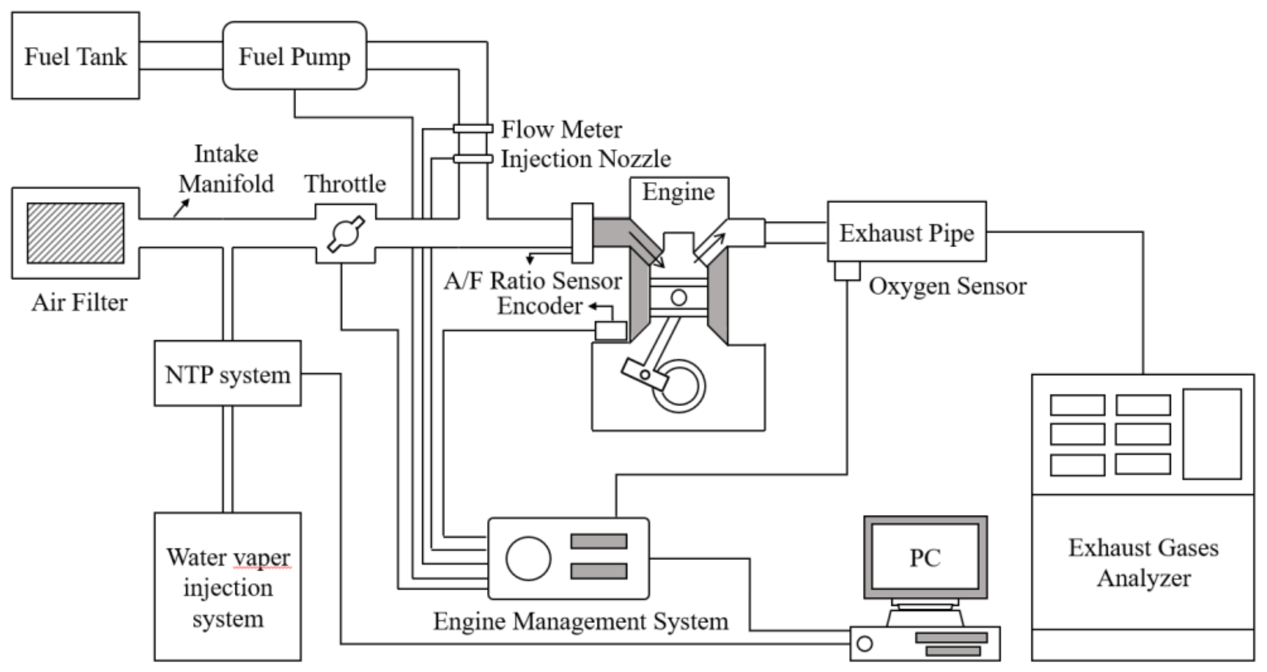
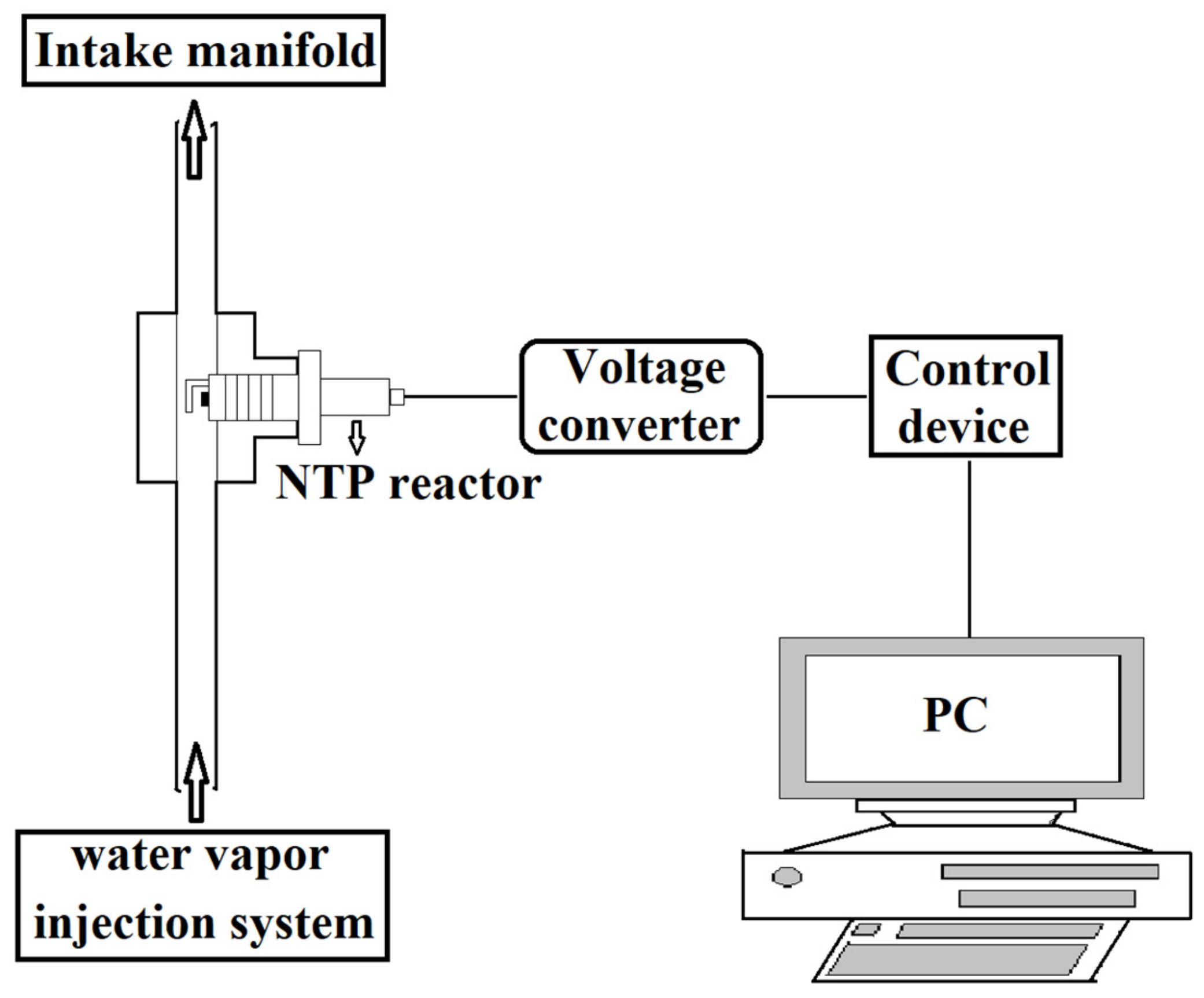
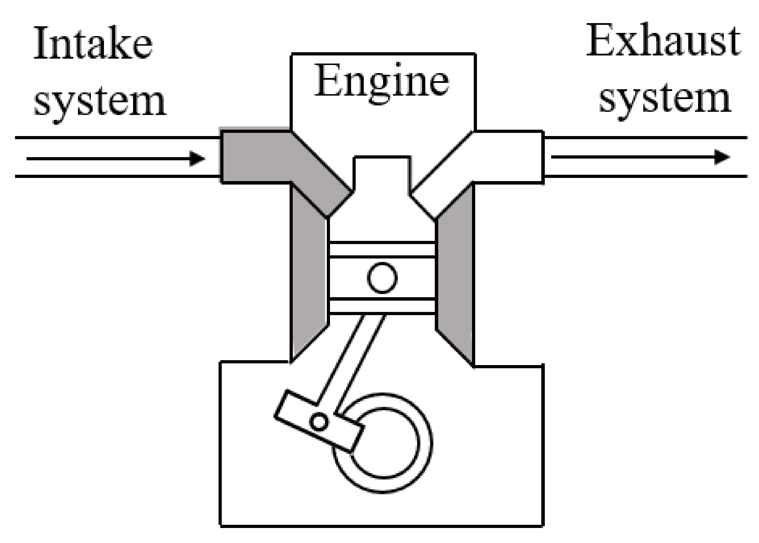
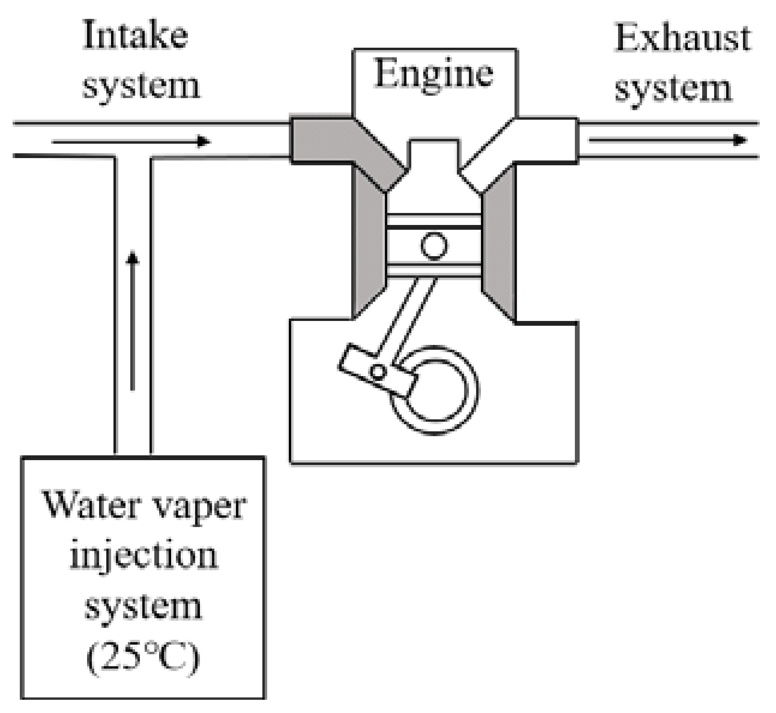
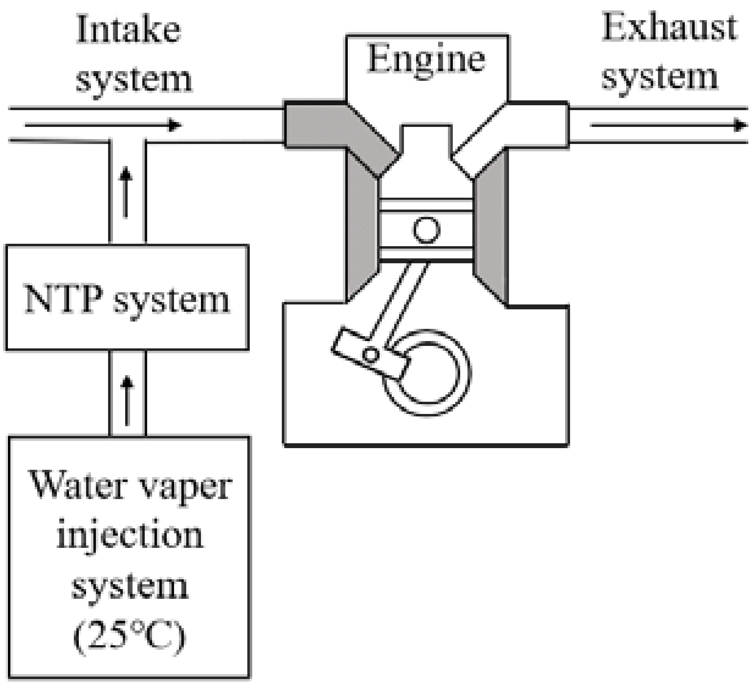
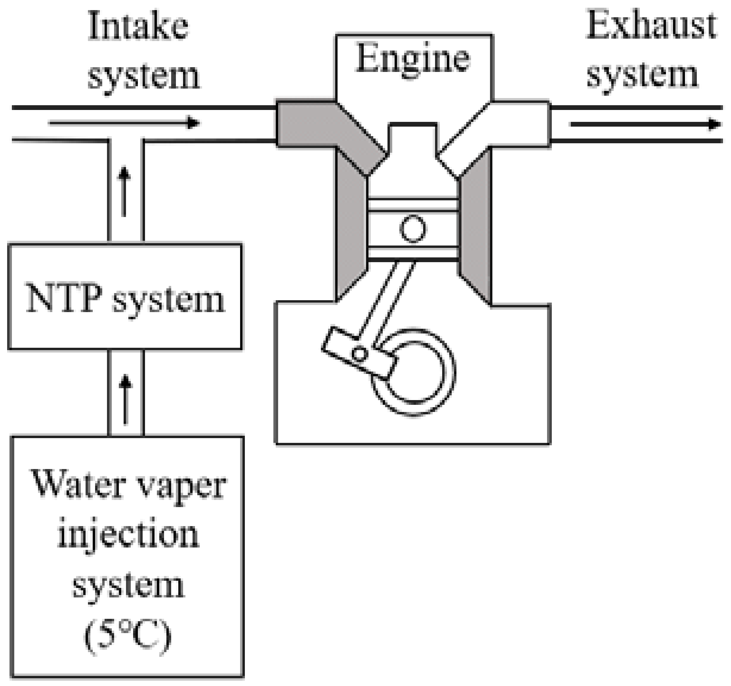
The experimental setup for this study consisted of an engine system, an NTP system, and a water vapor injection system, as shown in Figure 1. A photographic view of the device setup on the experimental motorcycle is shown in Figure 2. The detailed experimental setup of the engine system included the motorcycle engine, a motorcycle chassis dynamometer, and an exhaust gas analyzer. The motorcycle using conventional combustion engines for this test was the Cygnus-X 125 model manufactured by YAMAHA Co. Ltd. (Taoyuan City, Taiwan). Specifications of the engine are shown in Table 1, while the experimental control conditions are shown in Table 2. Excessive engine speed will produce high temperatures during lean combustion, easily causing engine damage. Therefore, the range of 4000–7000 rpm is frequently used in motorcycle engines for safety considerations. The A/F ratio was controlled at 10 to 14 because sparks would not be easy to ignite when exceeding 14, while the engine was easy to knock when the A/F ratio was less than 10. In order to smoothen the air flow in the intake manifold, only a 100% load was used. The engine performance was measured by a motorcycle chassis dynamometer—a Dynostar D50ECB manufactured by Dutch Dynamometers & Engineering Solutions BV (Noord-Brabant, Netherlands). The motorcycle’s rear wheel was parked on the drum of the motorcycle chassis dynamometer for measurement during the experiment. Meanwhile, the engine power was transmitted to the drum by spinning the rear wheel, and the power value was subsequently measured. An axis torque sensor was connected between the motorcycle and the dynamometer, and the signals of the drum sensor were interpreted by a dynamometer controller. The exhaust from the motorcycle was analyzed by an exhaust gas analyzer (model EF-306EN, Exford, Taipei City, Taiwan). The exhaust gases were collected from the end of the exhaust pipe, and the data were recorded for 5 min under a normal condition to calculate the data average.
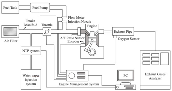
Figure 1.
Schematic of the experiment and set-up location.
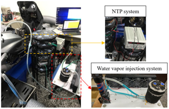
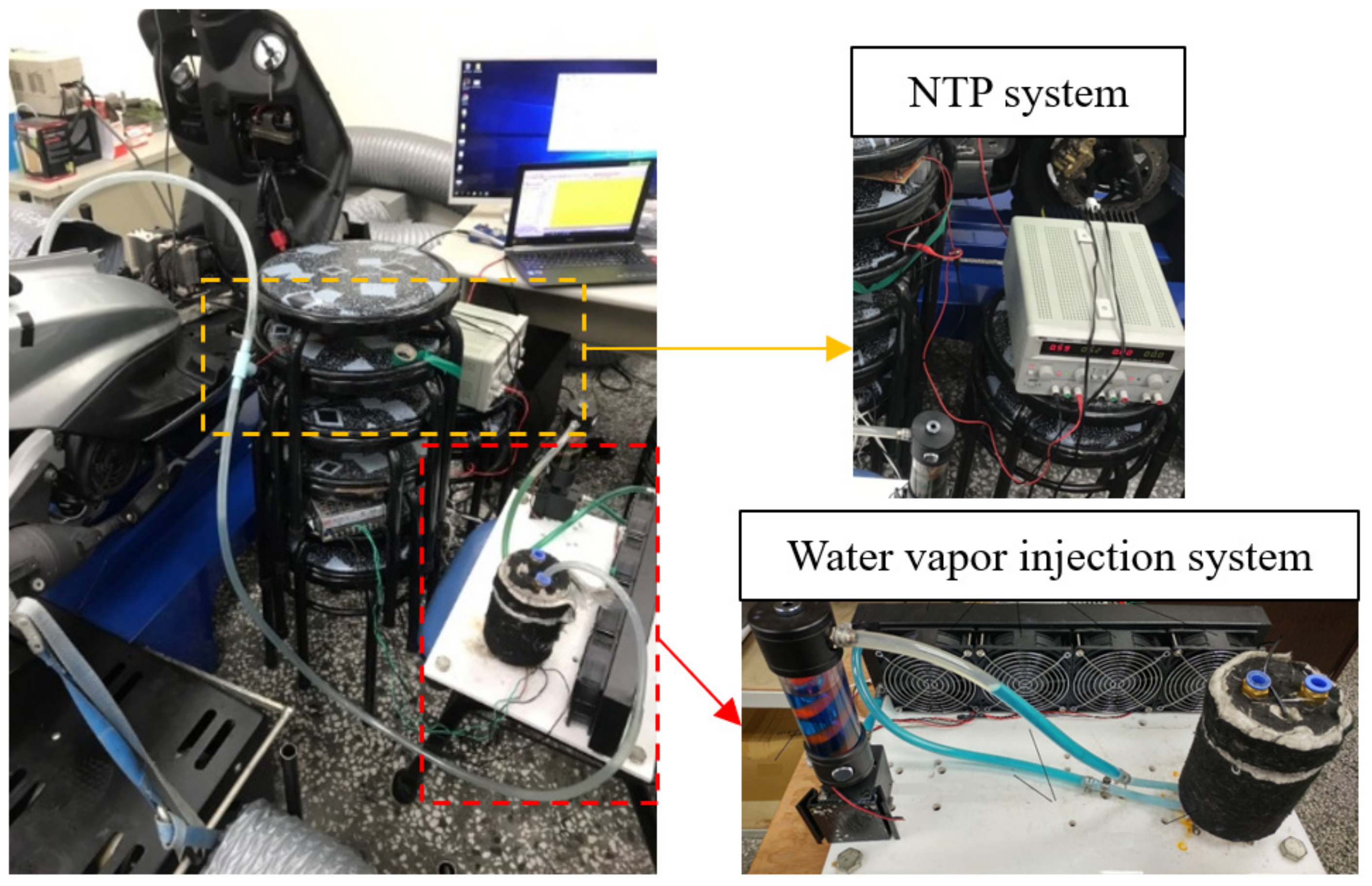
Figure 2.
Photographic view of the device set-up on the experimental motorcycle.

Table 1.
Engine specifications of the motorcycle.
Table 2.
Control conditions of the engine.
The NTP system’s detailed experimental setup—including an NTP reactor, a control device, and a voltage converter—is shown in Figure 3. The NTP reactor was a CR8EIX manufactured by NGK Spark Plug Co., Ltd. (Nagoya, Japan). Its specifications are shown in Table 3. The control device was Model No. DP-30032 (HILA International Inc., Taipei City, Taiwan). The voltage converter had Model No. 3051A-LGL3-900 (KYMCO Co., Ltd., Kaohsiung City, Taiwan). The voltage was set at 5 V and the spark frequency at 10 Hz. The NTP reactors’ spark output frequency was controlled by the control device. The low-voltage electric energy was converted into high-voltage after the voltage passed through the converter, which was then transmitted to the NTP reactor through the ignition wire. The NTP reactor generated a fixed frequency arc and degraded the water vapor.
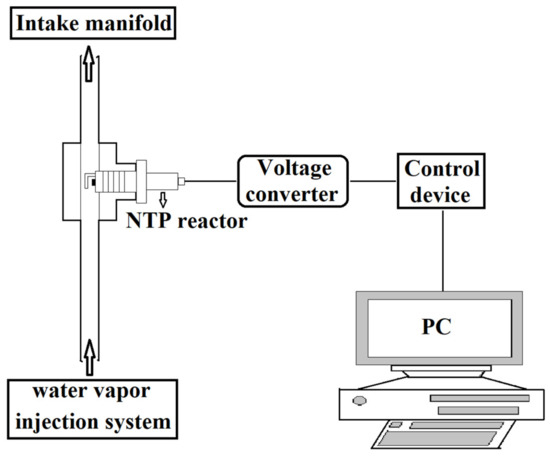
Figure 3.
Schematic of the NTP system.
Table 3.
Specifications of the NTP reactor.
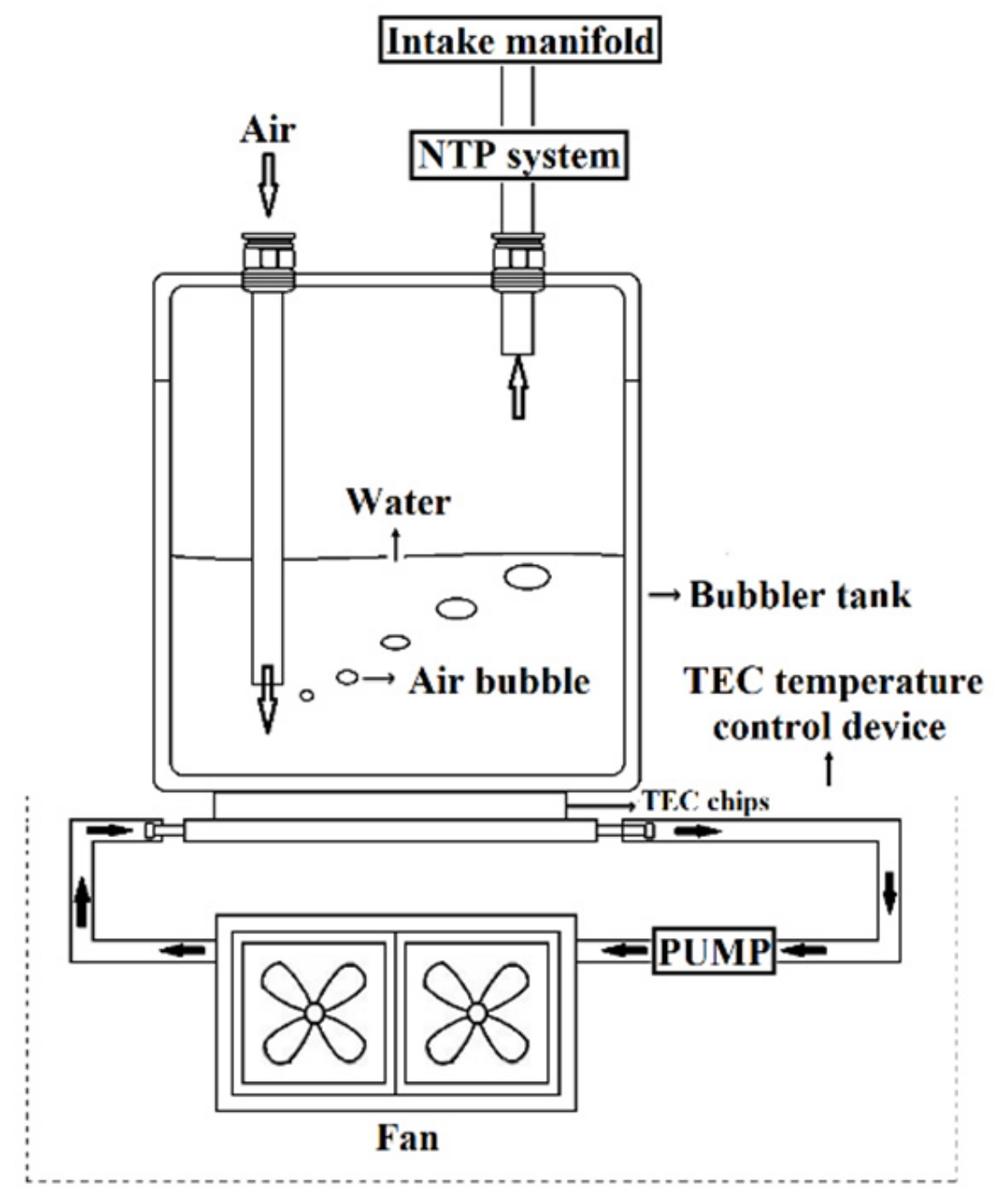
The experimental setup of a water vapor injection system—including a bubbler tank and a thermoelectric cooler (TEC) temperature control device—is illustrated in Figure 4. The ratio of gasoline and water vapor is 97.8:2.2 to 95.5:4.5, depending on engine speed and A/F ratio. One side of the bubbler tank allowed the atmosphere to enter; the other was connected to the intake manifold by an air pipe. The inner diameter of the air pipe was 12 mm; the airflow rate is listed in Table 4. The measurement took place between the intake manifold and the air filter. The airflow rate value was the difference between the closed air pipe and the opened air pipe. The flow meter was Model No. 3142U, manufactured by TES Electrical Electronic Corp. (Taipei City, Taiwan). The specifications of the bubbler tank are illustrated in Table 5. The bubbler tank, filled with water and the solubility of oxygen, is shown in Table 6. The dissolved oxygen meter was a DO-5512SD manufactured by Lutron Electronics, Inc. (Coopersburg, USA). A TEC chip was placed at the bottom of the bubbler tank, whose one side was connected to the bubbler tank, while the other was connected to the circulating water energy exchanger. Under the condition of an electric current passing through the TEC chip, an exothermic phenomenon appeared on one side of the chip, lowering the temperature, while an endothermic phenomenon appeared on the other side, raising the temperature. The bubbler tank’s water temperature was controlled by changing the direction of an electric current as it passes through the TEC chip. One side of the TEC chip was connected to the bubbler tank to add energy. Meanwhile, the other side was connected to the recirculating water energy exchanger to dissipate energy. The recycled water energy exchanger not only could exchange the energy from the bubbler tank but also develop pressure for the flow of the recycled water inside the recycled water energy exchanger. The recycled water flowed from the water-energy exchanger into the radiator to dissipate energy to the surroundings through a fan, then flowed back to the water-energy exchanger.
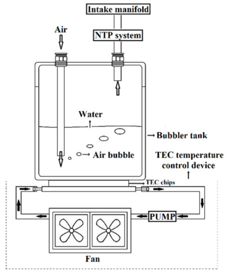
Figure 4.
Schematic of the water vapor injection system.
Table 4.
Airflow rate at different engine speeds.
Table 5.
Specifications of the bubbler tank.
Table 6.
Solubility of oxygen in water at different temperatures.
2.3. Experimental Procedure
The measuring equipment was corrected and adjusted before the experiment began. The preparation and measurement procedures were as follows:
- Motorcycle stuff was inspected and replaced, such as the air filter, oil, fuel oil, spark plug, and tire pressure;
- The exhaust gas analyzer was warmed up and calibrated;
- During the preparation period, the motorcycle engine was started, and the highest temperature measured was 80 °C;
- The temperature of water in the bubbler tank was checked;
- The NTP system was checked, and a new NTP reactor was replaced before each experiment.
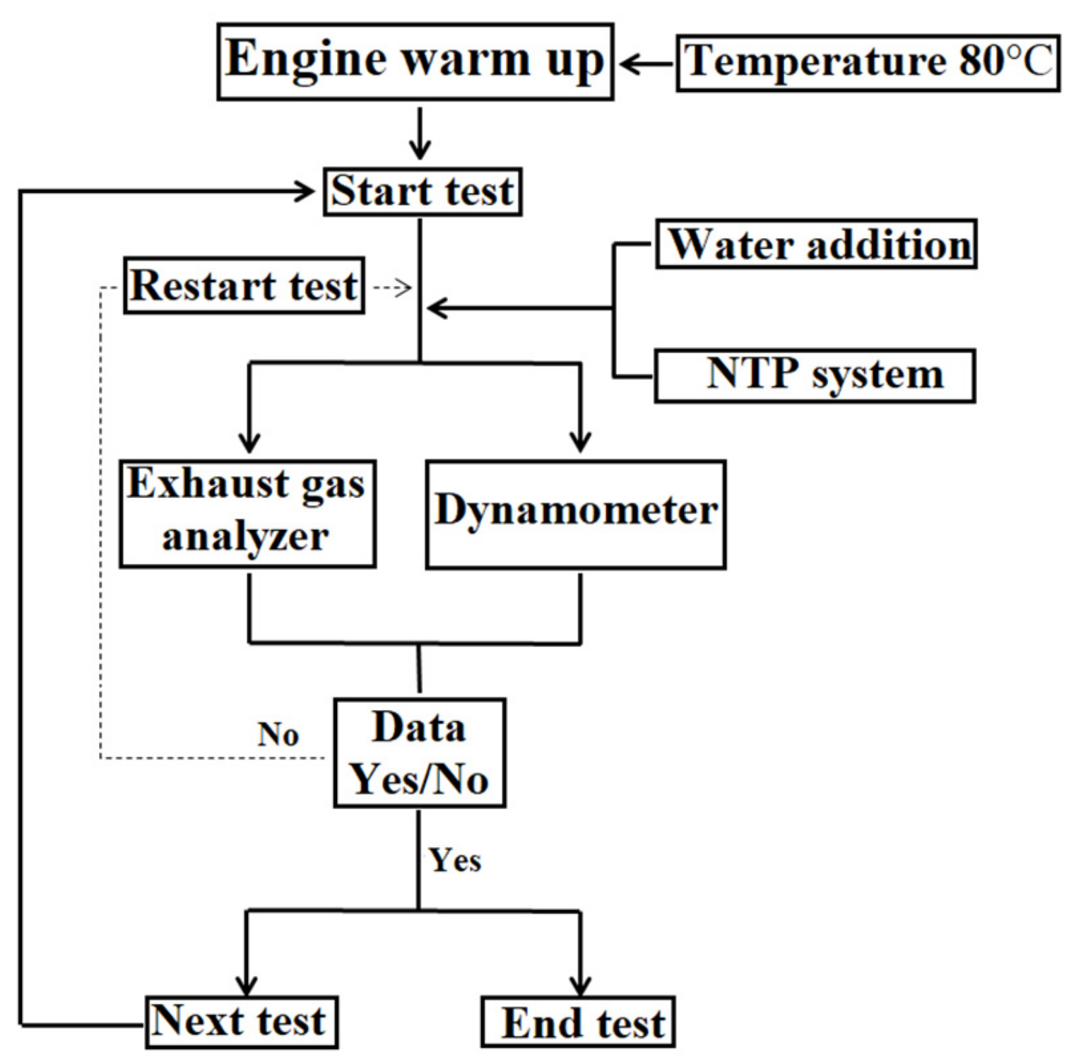
In this study, four main experiments were executed to measure the engine power and exhaust emissions. After measuring the engine speed, A/F ratio, water temperatures in the bubbler tank, and NTP system from the experiments, the results were compared to find a trend and correlations. The experimental procedure is shown in Figure 5. In each experiment, the engine speed was set at a specific number starting from 4000 rpm, which was increased by the interval of 1000 rpm ending at 7000 rpm. Meanwhile, the A/F ratio was adjusted between 10 and 14. The temperature of water in the bubbler tank was set to be either 5 ± 2 °C or 25 ± 2 °C. The voltage of the NTP system and the frequency were set to be 5 V and 10 Hz, respectively. There were four types of models, including Type A (original), Type B (25 °C water), Type C (25 °C water+NTP), and Type D (5 °C water+NTP), as illustrated in Table 7. A detailed list of acronyms and abbreviations can be found in Table 8.
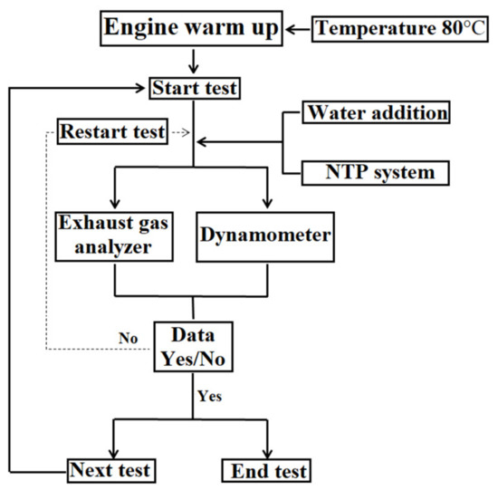
Figure 5.
Procedure schematic of the experimental method.
Table 7.
The test cases with the main specifications.
Table 8.
List and meaning of acronyms.
The dissociation process was defined as follows:
where CE is the conversion efficiency; C0 is the measured value from the original engine system; C is the value obtained after installing the water vapor injection system and NTP system.
3. Results and Discussion
3.1. Engine Performance
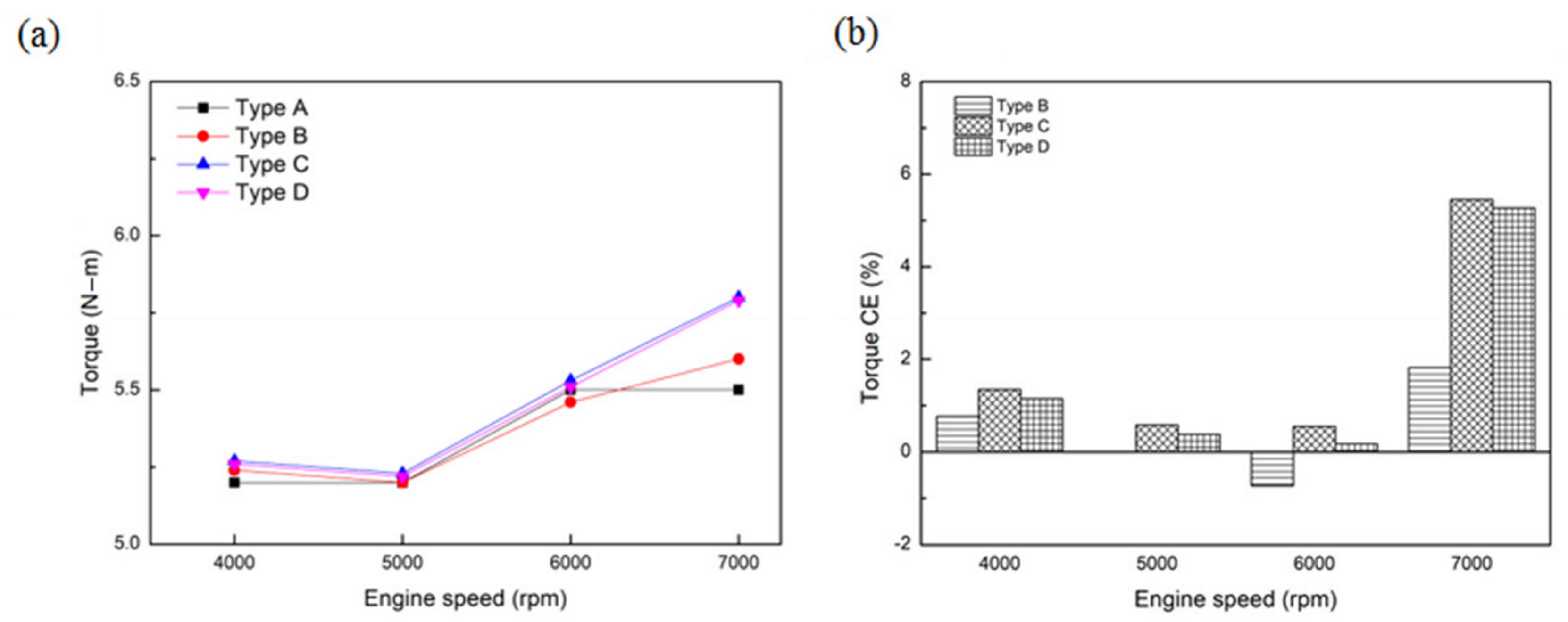
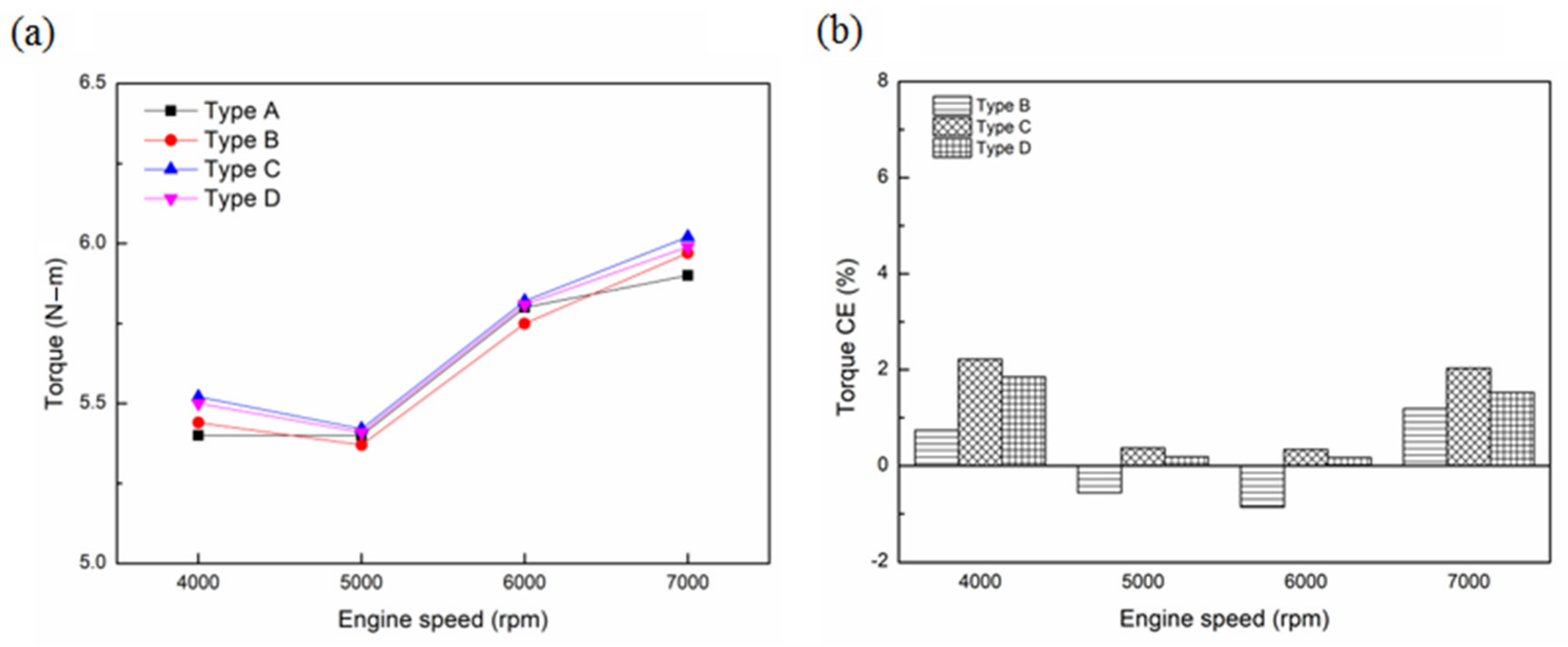
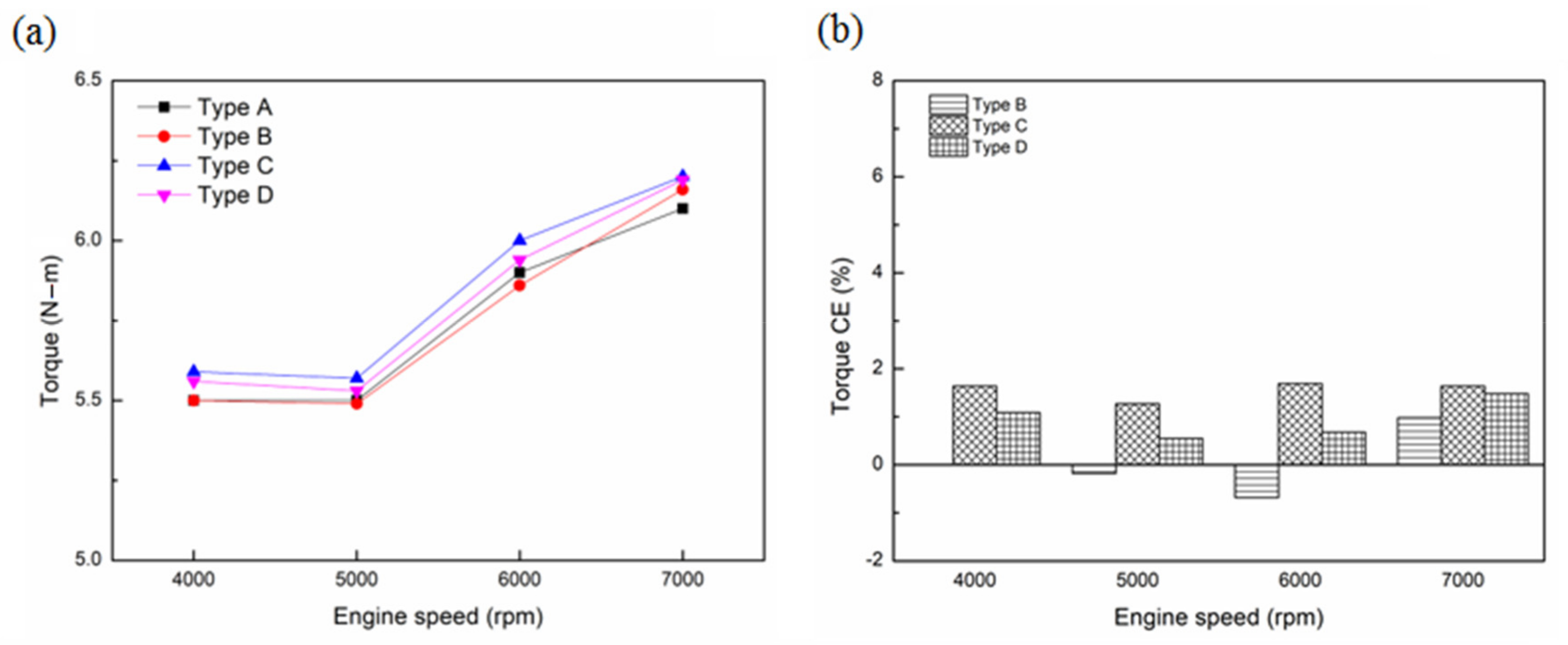
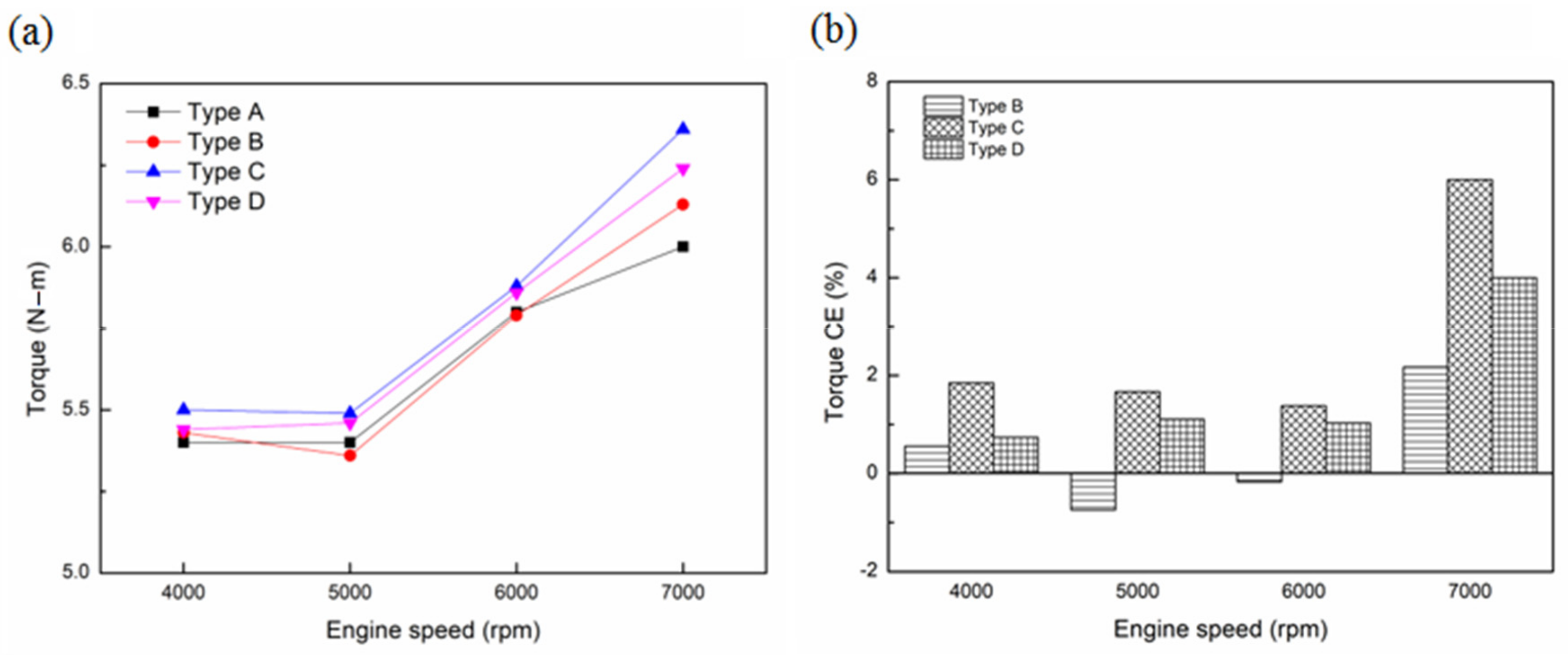
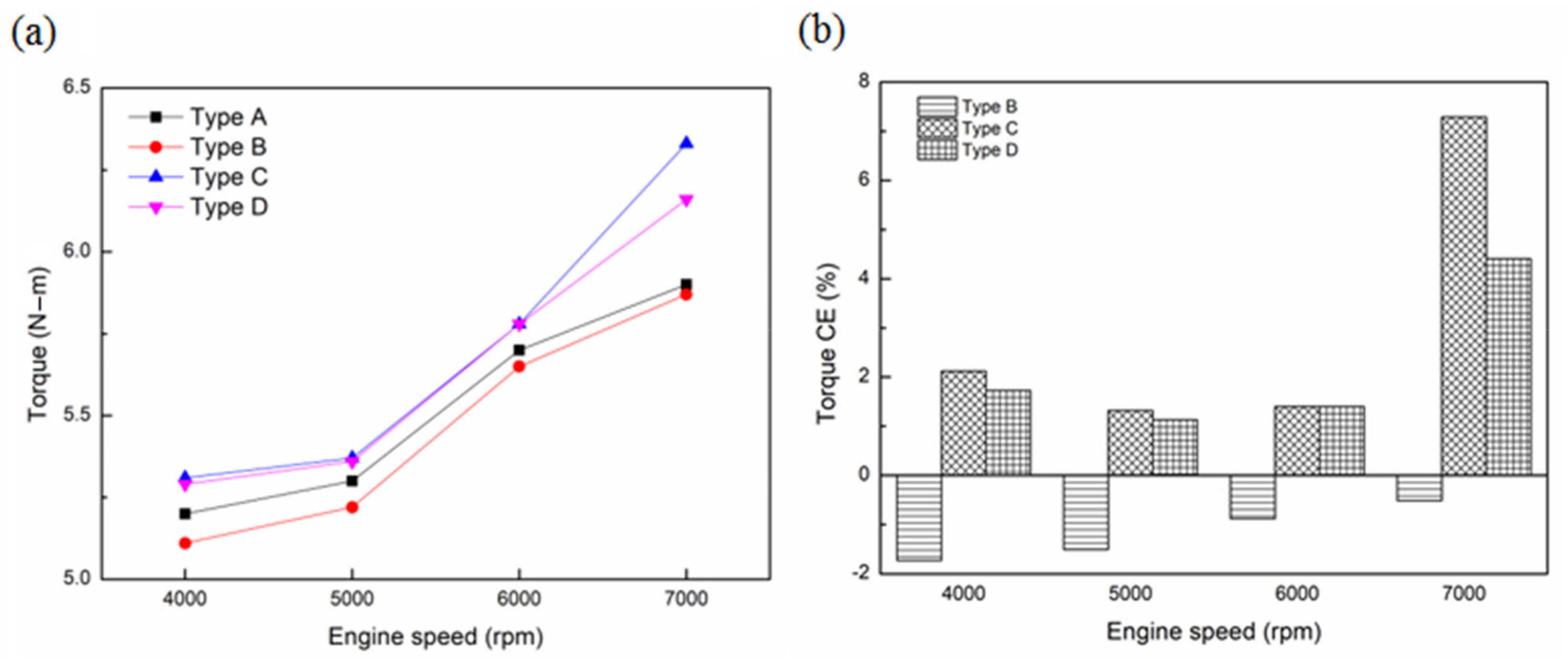
Figure 6, Figure 7, Figure 8, Figure 9 and Figure 10 show the torque values and conversion efficiency at the A/F ratio of 10–14. The result from the A/F ratio of 10 (Figure 6) demonstrated an increase in the torque conversion efficiency at most engine speeds. This increase resulted from the addition of water vapor to the intake system. By doing so, the quantity of the combustibles and combustion-supporting substances (e.g., H2 and O2) were increased in the combustion chamber. The degradation of water vapor through the NTP reactor provided additional combustibles and combustion-supporting substances for engine combustion, further aiding the combustion conditions [38]. The result from the A/F ratio of 11 (Figure 7) signified a reduction of the torque of Type B at 5000 and 6000 rpm. This is because water vapor reduces combustion flame speed of the cylinder charge and consequently reduces in-cylinder peak pressure. It causes a lower combustion temperature and combustion efficiency is negatively affected [39,40]. The result from the A/F ratio of 12 (Figure 8) specified that the combustion temperature gradually increased due to the reduction in fuel supply. Meanwhile, the effect of the combustibles and combustion-supporting substances on combustion efficiency was not evident at this A/F ratio. The results from the A/F ratio of 13 (Figure 9) implied the production of more combustibles and combustion-supporting substances, resulting from the degradation of water vapor under leaner combustion conditions. Therefore, the combustion efficiency at a high rpm was improved. The torque output of Type B was relatively low, which might be caused by the water vapor’s inability to increase the explosive kinetic energy after absorbing heat energy; hence, the combustion efficiency was lowered. The result from the A/F ratio of 14 (Figure 10) revealed that the water vapor’s torque under leaner combustion conditions was reduced, probably prompted by engine misfiring at this A/F ratio. In Types C and D, the degradation of water could produce combustibles and combustion-supporting substances before they enter the combustion chamber. Therefore, the torque was higher than the original performance, especially at a high rpm.
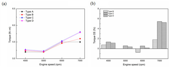
Figure 6.
(a) Torque values and (b) CE at the A/F ratio of 10.
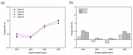
Figure 7.
(a) Torque values and (b) CE at the A/F ratio of 11.
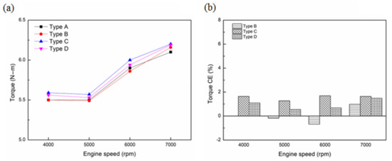
Figure 8.
(a) Torque values and (b) CE at the A/F ratio of 12.
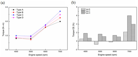
Figure 9.
(a) Torque values and (b) CE at the A/F ratio of 13.
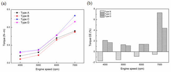
Figure 10.
(a) Torque values and (b) CE at the A/F ratio of 14.
3.2. Exhaust Emissions
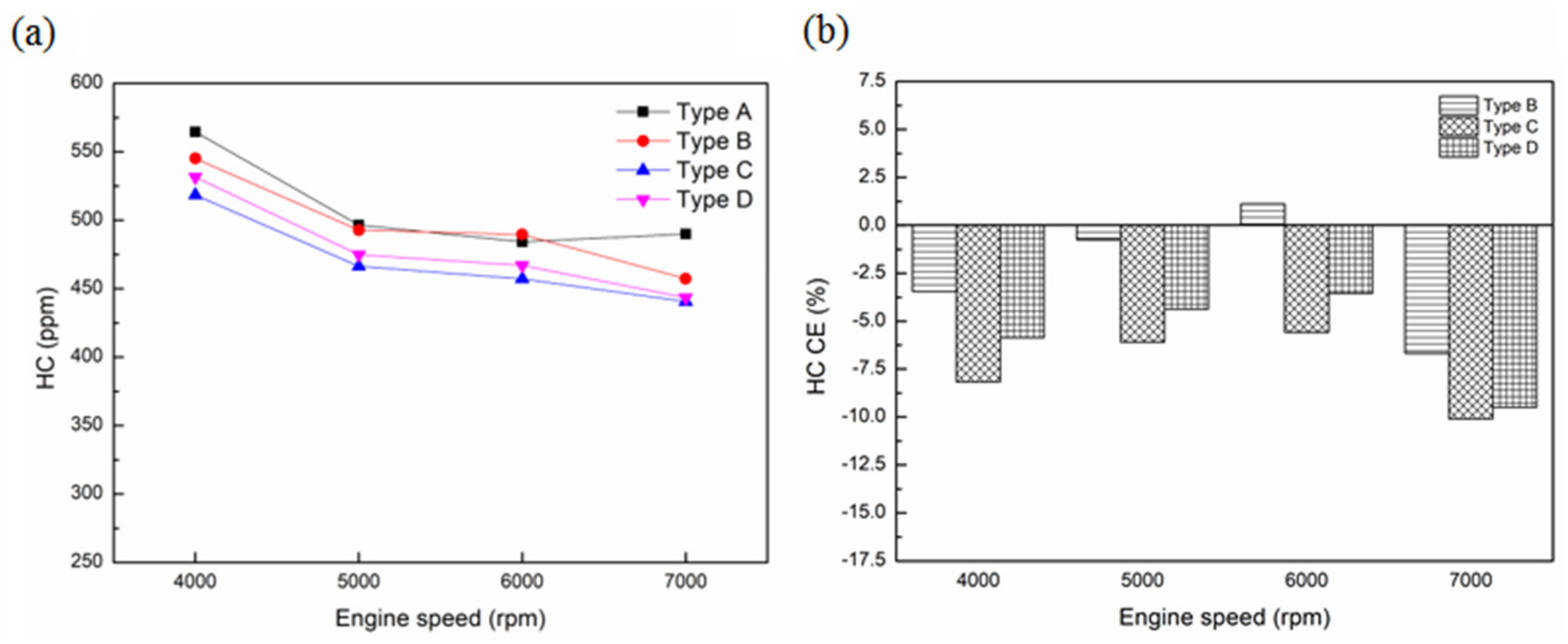
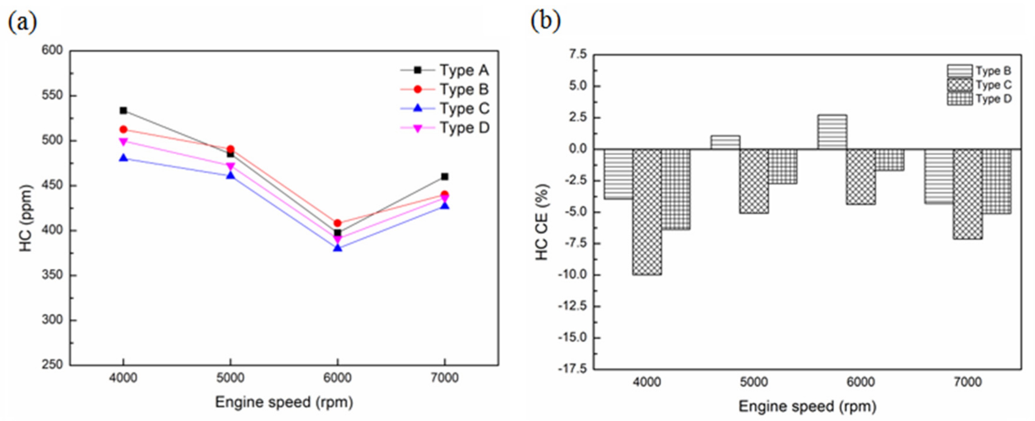
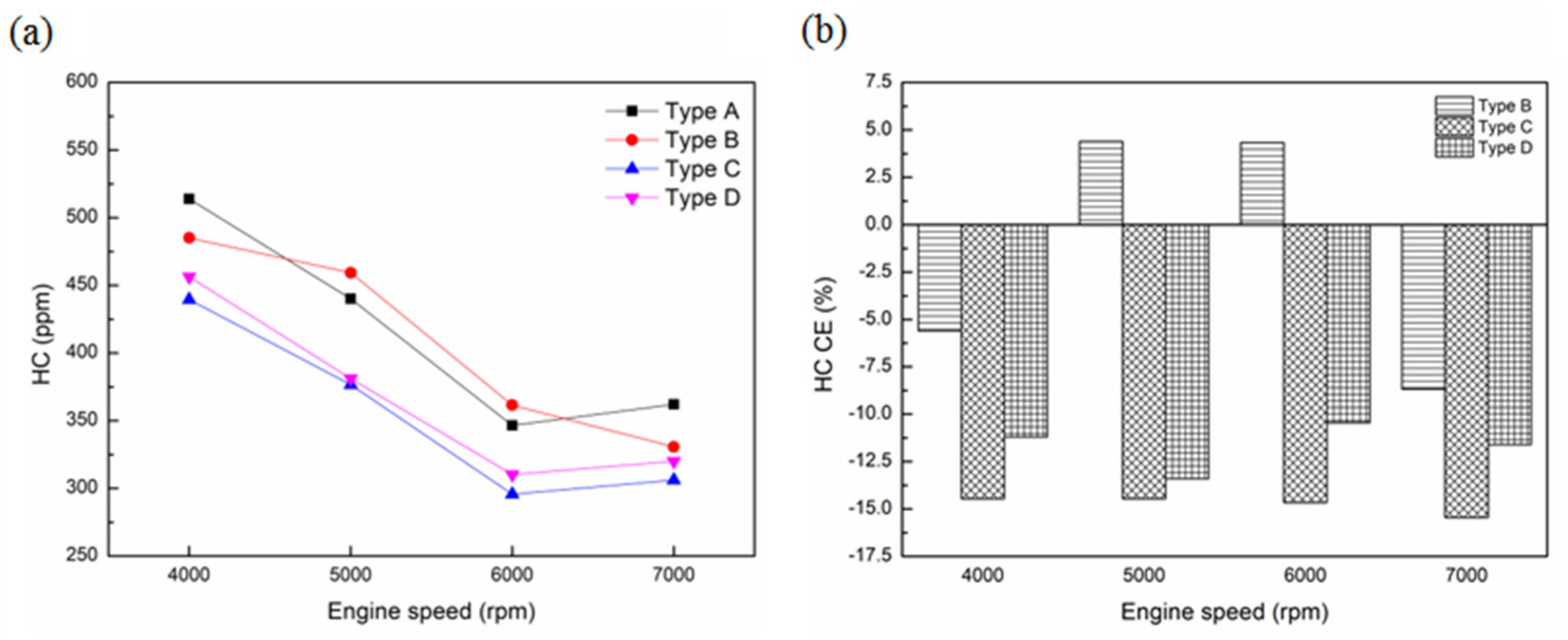
Figure 11, Figure 12, Figure 13, Figure 14 and Figure 15 show the HC emission values and conversion efficiency at the specified A/F ratio of 10–14. As the high burning velocity and wide flammability of hydrogen are effective in improving the combustion completeness [39], HC emissions were reduced with the addition of combustibles and combustion-supporting materials. The result from the A/F ratio of 10 (Figure 11) indicated a reduction in the HC values under Types C and D at various rpms, considering that the degradation of water vapor through the NTP reactor might have aided the combustion-supporting effect. Meanwhile, the HC emission under Type B at 6000 rpm was increased, indicating that the addition of water vapor helped in absorbing heat energy and destroying the combustion environment under these conditions, leading to reduced combustion efficiency. The result from the A/F ratio of 11 (Figure 12) demonstrated that the water vapor’s dissociation through the NTP system produced combustibles and combustion-supporting substances, which boosted combustion efficiency. When HC is dissociated into H2O, the emission from motorcycles is greatly reduced. The results from Type D were worse than those from Type C as the lower-temperature water vapor absorbed part of the combustion heat and affected the HC combustion. The experimental results from the A/F ratio of 12 (Figure 13) appeared to be similar to those from the A/F ratio of 11 (Figure 12). The HC emission CE under the lower-temperature water vapor was 11%–14%, indicating that the lower-temperature water vapor had a greater impact on the combustion environment. The result from the A/F ratio of 13 (Figure 14) indicated an increase in HC emissions under the water vapor at 5000 and 6000 rpm, further demonstrating the water vapor’s ability to induce a misfire, resulting in incomplete combustion inside the engine. The result from the A/F ratio of 14 (Figure 15) disclosed an increase in HC emissions under Type B, illustrating the water vapor’s ability to prompt a misfire after absorbing heat energy, leading to incomplete combustion.

Figure 11.
(a) HC emission values and (b) CE at the A/F ratio of 10.
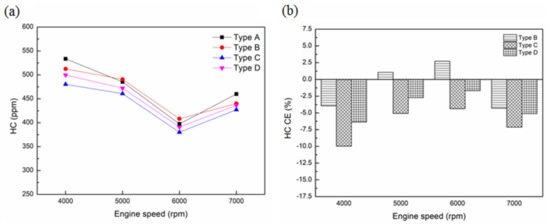
Figure 12.
(a) HC emission values and (b) CE at the A/F ratio of 11.
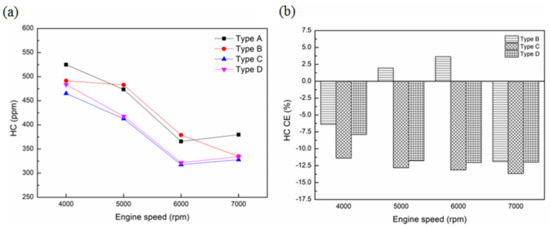
Figure 13.
(a) HC emission values and (b) CE at the A/F ratio of 12.
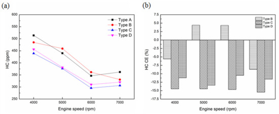
Figure 14.
(a) HC emission values and (b) CE at the A/F ratio of 13.

Figure 15.
(a) HC emission values and (b) CE at the A/F ratio of 14.
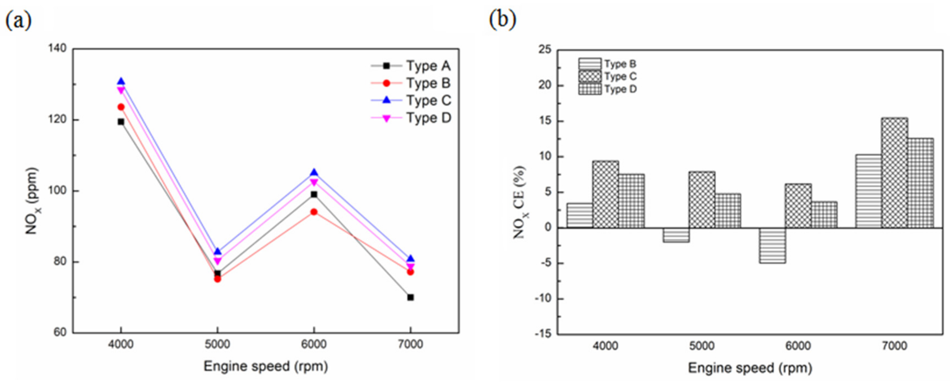
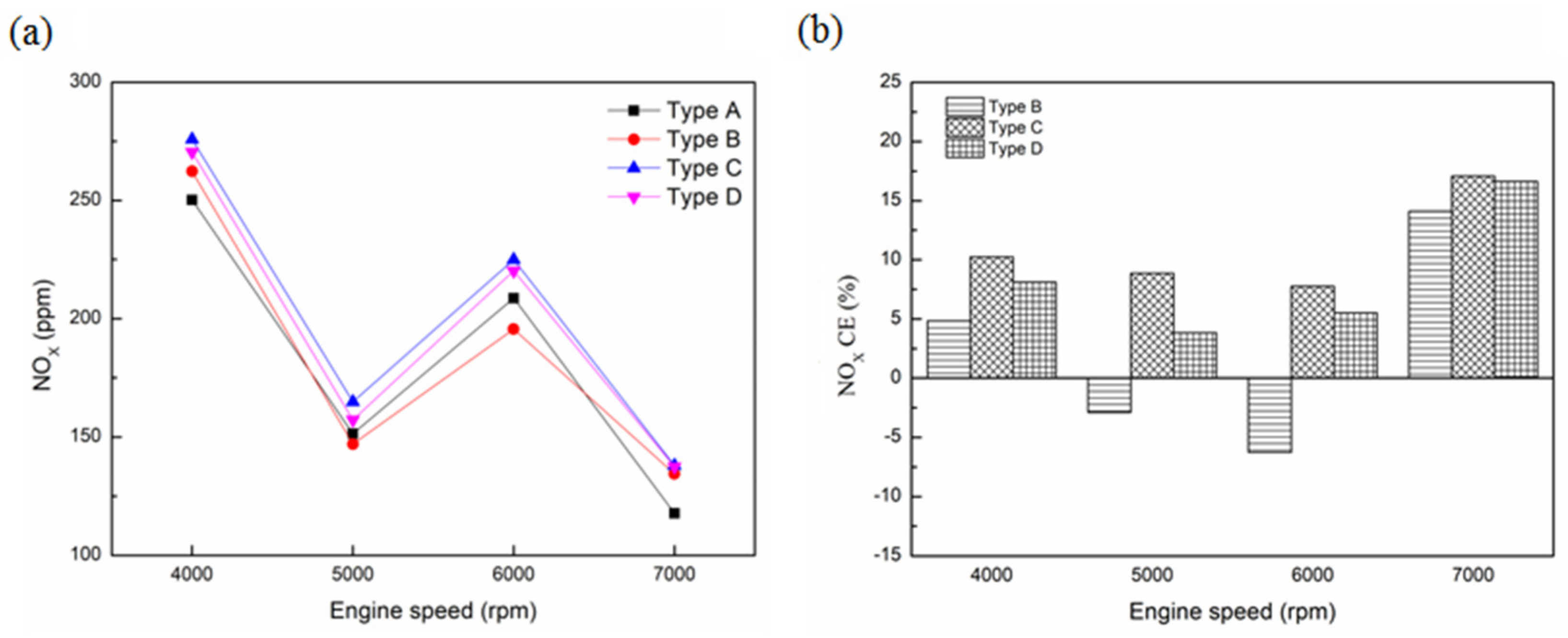
Figure 16, Figure 17, Figure 18, Figure 19 and Figure 20 display the NOx emission values and conversion efficiency at an A/F ratio of 10–14. After adding combustibles and combustion-supporting materials, most NOx was increased due to the high flame temperature and fast burning velocity of hydrogen [39]. The result from the A/F ratio of 10 (Figure 16) unveiled that the NOx emission CE at each specified rpm was mostly higher than that from the original engine system, indicating that, in addition to the absorption of heat by the water vapor, the NTP system increased the amount of the combustibles and combustion-supporting substances and raised the combustion temperatures. The result from the A/F ratio of 11 (Figure 17) presented a sharp increase in the NOx emissions after water vapor was added through the NTP system. However, those in Type C were lower than those in Type B, indicating that the NOx has had high sensitivity to combustion temperatures. The result from the A/F ratio of 12 (Figure 18) revealed that the NOx emission values with the addition of the NTP system were higher than the original engine system. Meanwhile, the NOx emission CE was higher than those from the A/F ratio of 10 (Figure 16) and 11 (Figure 17), indicating that the combustion temperature after adding water vapor has been much higher than the absorbed heat. In addition, the NOx emission CE from Type B at 5000 and 6000 rpm decreased, which was probably prompted by the misfiring of the engine and incomplete combustions. In the A/F ratio of 13 (Figure 19), the experimental results were similar to those from the A/F ratio of 12 (Figure 18), except that there is an increase in the NOx emission CE, indicating that the higher-temperature condition generated by lean combustion has had a considerable impact on NOx emissions. The result from the A/F ratio of 14 (Figure 20) also revealed that the NOx emission under Type B at 4000–7000 rpm was reduced, indicating that the absorption of heat energy by the water vapor under these lean combustion conditions has directly affected combustion temperature.
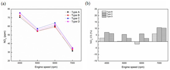
Figure 16.
(a) NOx emission values and (b) CE at the A/F ratio of 10.

Figure 17.
(a) NOx emission values and (b) CE at the A/F ratio of 11.
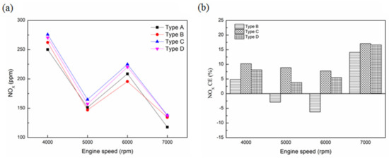
Figure 18.
(a) NOx emission values and (b) CE at the A/F ratio of 12.
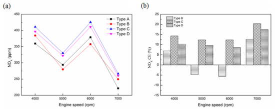
Figure 19.
(a) NOx emission values and (b) CE at the A/F ratio of 13.
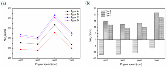
Figure 20.
(a) NOx emission values and (b) CE at the A/F ratio of 14.
3.3. Different A/F Ratios
Figure 21 shows the torque conversion efficiency at 4000–7000 rpm. The results disclosed an increase in most torque measurements and an increase of about 7.29% in the torque conversion efficiency under Type C at the A/F ratio of 14, as shown in Figure 21d. After applying the water vapor system to the NTP system, the torque was not only higher than that from the original engine system but was also higher than that from the water vapor system. This finding indicates that the degradation of water vapor through the NTP reactor before it entered the engine led to the production of combustibles and combustion-supporting substances, which could promote the formation of the homogenous gasoline–air–hydrogen mixture and enhance the degree of constant-volume combustion, subsequently improving combustion in the combustion chamber [39].
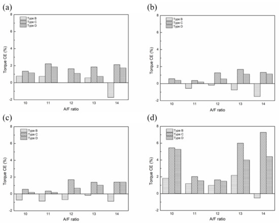
Figure 21.
Torque CE at (a) 4000; (b) 5000; (c) 6000; and (d) 7000 rpm.
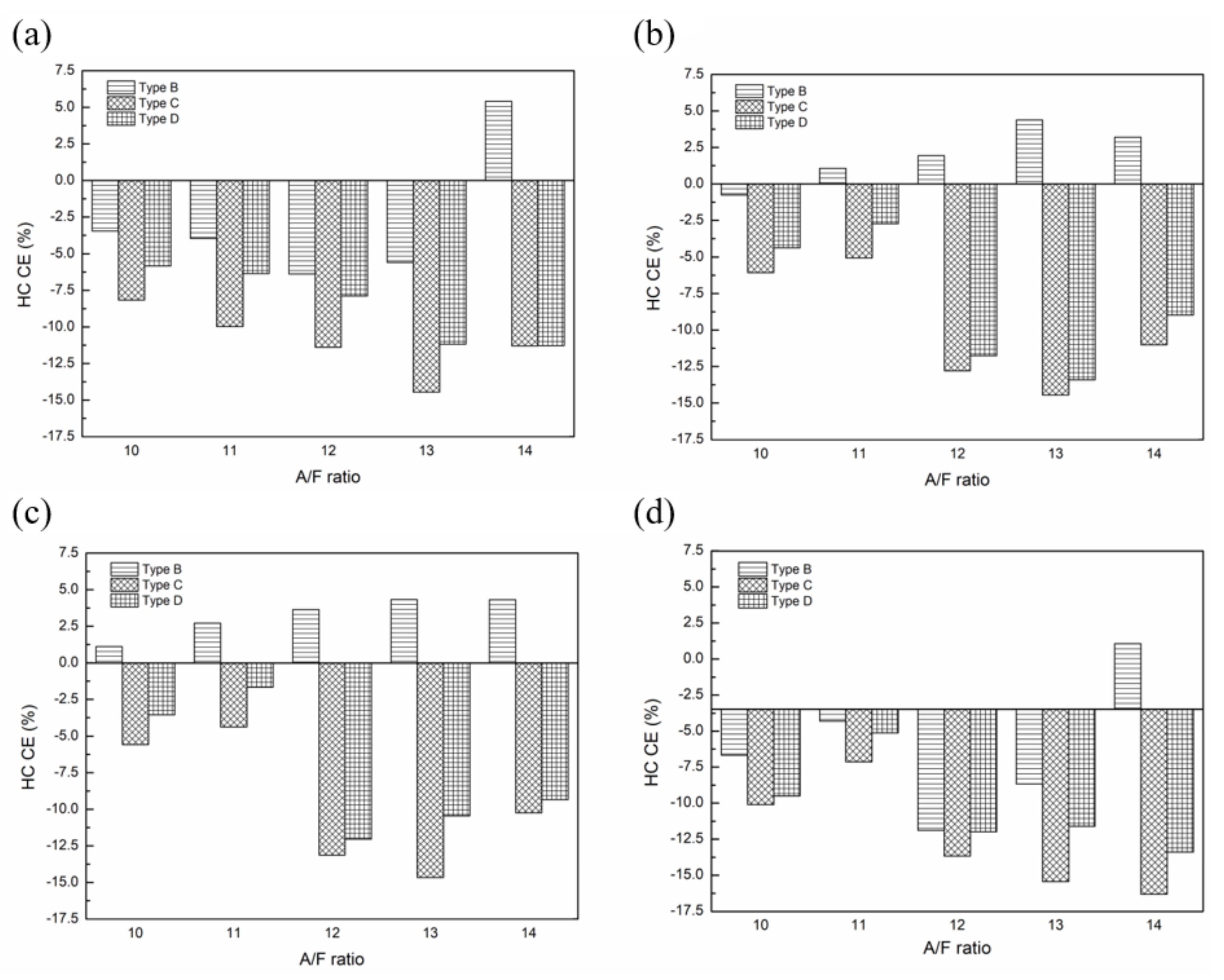
Figure 22 illustrates the HC emission conversion efficiency at 4000–7000 rpm. The results revealed that HC emissions were reduced in most cases, with its conversion efficiency under Type C at the A/F ratio of 14 reduced by about 16.31%, as shown in Figure 22d. The reduction of HC emissions is due to the absence of carbon in combustible substances and better fuel combustion with the aid of combustibles and combustion-supporting substances that have a higher flame speed [41].

Figure 22.
HC emission CE at (a) 4000; (b) 5000; (c) 6000; and (d) 7000 rpm.
Figure 23 shows the NOx emission conversion efficiency at 4000–7000 rpm. The results disclosed that the NOx emissions increased in the majority of cases, with its conversion efficiency under Type C at the A/F ratio of 14 increased by about 21.58%, as shown in Figure 23d. This phenomenon was caused by the addition of combustibles and combustion-supporting substances. A higher flame speed of hydrogen might have caused peak pressure, and the fuel temperature under the excessive condition increased the combustion temperature, causing a sharp rise in NOx emissions [41]. Finally, we provided a summary of the main results in Table 9.
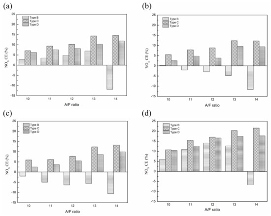
Figure 23.
NOx emission CE at (a) 4000; (b) 5000; (c) 6000; and (d) 7000 rpm.
Table 9.
A summary of the main results.
4. Conclusions
In this study, air-assisted combustion devices—including a water vapor injection system and an NTP system—were applied to a motorcycle to investigate their effects on engine performance and exhaust emissions. The water temperature in the bubbler tank was controlled using a thermoelectric module, and the water vapor was dissociated by employing an NTP reactor to add the engine combustion. The effects of the above-mentioned air-assisted combustion devices were as follows:
- The addition of water vapor in the engine had a positive influence on combustion as the degradation of water vapor through the NTP reactor produced combustibles and combustion-supporting substances in aiding engine combustion;
- In terms of the torque, the original engine system’s maximum torque was about 6000 rpm. However, the maximum torque values under A/F ratios of 13 and 14 at 7000 rpm were delayed by the adaptation of an air-assisted combustion device, indicating the effectiveness of combustibles and combustion-supporting substances at a high rpm in fuel burning;
- In terms of the HC emissions, adding an NTP system to a water vapor injection system effectively reduced the HC values. The Type D model’s HC emission conversion efficiency effect was worse than that of the Type C model because a higher combustion temperature in the engine could not be reached;
- In terms of the NOx emissions, adding water vapor + NTP prompted an increase in NOx emissions under most circumstances, especially at a larger A/F ratio. This increase might have been caused by improved combustion efficiency and increased combustion temperature. Nonetheless, the sole addition of water vapor could have a cooling effect, reducing the NOx values;
- In terms of the A/F ratio, the results from Type C and D models disclosed an improved engine performance and an effective reduction in HC emissions. Due to complete combustions, the NOx values were raised.
In conclusion, these systems might be a solution for exhaust gases and a key element in improving the current and future SI and diesel engines. In addition, the NTP system has been adapted in the exhaust system to reduce NOx and HC [32]. Based on our findings from this study, the above methods can hopefully aid in providing a sustainable environmental future in the transport sector.
Author Contributions
M.-H.H. guided the research direction, found the solutions, and designed the approach to set up the testing facility, designed and executed mechanical tests; C.-J.L. and M.-C.H. wrote the initial draft of the paper; S.-H.W. and C.-H.H. conducted the experiments and collected the results. C.-Y.P. and W.-C.H. analyzed the experimental results from this study. All authors have read and agreed to the published version of the manuscript.
Funding
This paper is supported by the Ministry of Science and Technology (MOST) and the National Kaohsiung University of Science and Technology under MOST-109-2622-E-992-015-CC3.
Acknowledgments
The author would like to thank the Ministry of Science and Technology (MOST) and the National Kaohsiung University of Science and Technology for their financial support on this study.
Conflicts of Interest
The author declares no conflict of interest.
References
- R.O.C. Ministry of Transportation and Communications. (December 2020). Monthly Traffic Statistics Report. Retrieved July 17, 2021, from Ministry of Transportation and Communications Reports Online via GPO Access: https://stat.motc.gov.tw/mocdb/stmain.jsp?sys=220&ym=10101%20&ymt=11006&kind=21&type=9&funid=b330106&cycle=41&outmode=0&compmode=0&outkind=1&fld1=1&fld21=1&codspc0=0,4,&rdm=xm9bhKm9.
- Gupta, K.; Suthar, K.; Jain, S.K.; Agarwal, G.D.; Nayyar, A. Design and experimental investigations on six-stroke SI engine using acetylene with water injection. Environ. Sci. Pollut. Res. 2018, 25, 23033–23044. [Google Scholar] [CrossRef]
- Das, L.M. Near-term introduction of hydrogen engines for automotive and agriculture application. Int. J. Hydrog. Energy 2002, 27, 479–487. [Google Scholar] [CrossRef]
- Saravanan, N.; Nagarajan, G. Experimental investigation on a DI dual fuel engine with hydrogen injection. Int. J. Energy Res. 2009, 33, 295–308. [Google Scholar] [CrossRef]
- R.O.C. Air Pollution Control Act; Environmental Law Library: Taipei, Taiwan.
- Belgiornoa, G.; Di Blasio, G.; Shamun, S.; Beatrice, C.; Tunestål, P.; Tunér, M. Performance and emissions of diesel-gasoline-ethanol blends in a light duty compression ignition engine. Fuel 2018, 217, 78–90. [Google Scholar] [CrossRef]
- Monsalve-Serrano, J.; Belgiorno, G.; Di Blasio, G.; Guzmán-Mendoza, M. 1D simulation and experimental analysis on the effects of the injection parameters in methane–diesel dual-fuel combustion. Energies 2020, 13, 3734. [Google Scholar] [CrossRef]
- Sayin Kul, B.; Ciniviz, M. An evaluation based on energy and exergy analyses in SI engine fueled with waste bread bioethanol-gasoline blends. Fuel 2021, 286, 119375. [Google Scholar] [CrossRef]
- Parlak, A.; Ayhan, V.; Cesur, I. Effects of water steam injection on direct injection diesel engine operating with partial loads. J. Energy Inst. 2013, 86, 202–209. [Google Scholar] [CrossRef]
- Ricardo, H.R. The High-Speed Internal-Combustion Engine; Blackie & Son Limited: Glasgow, UK, 1935. [Google Scholar]
- Armasa, O.; Ballesteros, R.F.; Martos, J.; Agudel, J.R. Characterization of light duty diesel engine pollutant emissions using water-emulsified fuel. Fuel 2005, 84, 1011–1018. [Google Scholar] [CrossRef]
- Maiboom, A.; Tauzia, X. NOx and PM emissions reduction on an automotive HSDI diesel engine with water-in-diesel emulsion and EGR: An experimental study. Fuel 2011, 90, 3179–3192. [Google Scholar] [CrossRef]
- Ryu, K.; Oh, Y. Effect of water induction on the performance and exhaust emissions in a diesel engine (II). KSME Int. J. 2004, 18, 1640–1647. [Google Scholar] [CrossRef]
- Ma, X.; Zhang, F.; Han, K.; Zhu, Z.; Liu, Y. Effects of intake manifold water injection on combustion and emissions of diesel engine. Energy Procedia 2014, 61, 777–781. [Google Scholar] [CrossRef] [Green Version]
- Kim, J.; Park, H.; Bae, C.; Choi, M.; Kwak, Y. Effects of water direct injection on the torque enhancement and fuel consumption reduction of a gasoline engine under high-load conditions. Int. J. Engine Res. 2016, 17, 795–808. [Google Scholar] [CrossRef]
- Nour, M.; Kosaka, H.; Sato, S.; Bady, M.; Abdel-Rahman, A.K.; Uchida, K. Effect of ethanol/water blends addition on diesel fuel combustion in RCM and DI diesel engine. Energy Convers. Manag. 2017, 149, 228–243. [Google Scholar] [CrossRef]
- Kumar, M.S.; Karthic, S.V.; Pradeep, P. Investigations on the influence of ethanol and water injection techniques on engine’s behavior of a hydrogen-biofuel based dual fuel engine. Int. J. Hydrog. Energy 2018, 43, 21090–21101. [Google Scholar] [CrossRef]
- Marchitto, L.; Tornatore, C.; Costagliola, M.A.; Iacobacci, A.; Valentino, G. Effect of water injection on fuel efficiency and gaseous and PN emissions in a downsized turbocharged SI engine. J. Energy Eng. 2018, 144, 04018044. [Google Scholar] [CrossRef]
- Bahri, M.; Haghighat, F.; Rohani, S.; Kazemian, H. Impact of design parameters on the performance of non-thermal plasma air purification system. Chem. Eng. J. 2016, 302, 204–212. [Google Scholar] [CrossRef]
- Xu, S.; Whitehead, J.C.; Martin, P.A. CO2 conversion in a non-thermal, barium titanate packed bed plasma reactor: The effect of dilution by Ar and N2. Chem. Eng. J. 2017, 327, 764–773. [Google Scholar] [CrossRef]
- Hao, H.; Wu, B.S.; Yang, J.; Guo, Q.; Yang, Y.; Li, Y.W. Non-thermal plasma enhanced heavy oil upgrading. Fuel 2015, 149, 162–173. [Google Scholar] [CrossRef]
- Cheng, Y.L.; Wang, Y.K.; Chen, P.; Deng, S.B.; Ruan, R. Non-thermal plasma assisted polymer surface modification and synthesis: A review. Int. J. Agric. Biol. Eng. 2014, 7, 1–9. [Google Scholar] [CrossRef]
- Samukawa, S.; Hori, M.; Rauf, S.; Tachibana, K.; Bruggeman, P.; Kroesen, G.; Whitehead, J.C.; Murphy, A.B.; Gutsol, A.F.; Starikovskaia, S.; et al. The 2012 plasma roadmap. J. Phys. D Appl. Phys. 2012, 45, 253001. [Google Scholar] [CrossRef]
- Ombrello, T.; Won, S.H.; Ju, Y.; Williams, S. Flame propagation enhancement by plasma excitation of oxygen. Part I: Effects of O3. Combust. Flame 2010, 157, 1906–1915. [Google Scholar] [CrossRef]
- Aerts, R.; Snoeckx, R.; Bogaerts, A. In-situ chemical trapping of oxygen after the splitting of carbon dioxide by plasma. Plasma Process. Polym. 2014, 11, 985–992. [Google Scholar] [CrossRef]
- Uhm, H.S.; Kwak, H.S.; Hong, Y.C. Carbon dioxide elimination and regeneration of resources in a microwave plasma torch. Environ. Pollut. 2016, 211, 191–197. [Google Scholar] [CrossRef] [PubMed]
- Janda, M.; Martisovits, V.; Hensel, K.; Machala, Z. Generation of antimicrobial NOx by atmospheric air transient spark discharge. Plasma Chem. Plasma Process 2016, 36, 767–781. [Google Scholar] [CrossRef]
- Bahri, M.; Haghighat, F.; Rohani, S.; Kazemian, H. Metal organic frameworks for gas-phase VOCs removal in a NTP-catalytic reactor. Chem. Eng. J. 2017, 320, 308–318. [Google Scholar] [CrossRef]
- Kim, G.T.; Seo, B.H.; Lee, W.J.; Park, J.; Kim, M.K.; Lee, S.M. Effects of applying non-thermal plasma on combustion stability and emissions of NOx and CO in a model gas turbine combustor. Fuel 2017, 194, 321–328. [Google Scholar] [CrossRef]
- Mohapatro, S.; Sharma, N.K.; Madhukar, A. Abatement of NOx using compact high voltage pulse power supply: Towards retrofitting to automobile vehicle. IEEE Trans. Dielectr. Electr. Insul. 2017, 24, 2738–2745. [Google Scholar] [CrossRef]
- Hwang, J.; Kim, W.; Bae, C.; Choe, W.; Cha, J.; Woo, S. Application of a novel microwave-assisted plasma ignition system in a direct injection gasoline engine. Appl. Energy 2017, 205, 562–576. [Google Scholar] [CrossRef]
- Hsueh, M.H.; Wang, C.N.; Hsieh, M.C.; Lai, C.J.; Wang, S.H.; Hsieh, C.H.; Wu, T.L.; Yu, J.H. An analysis of exhaust emission of the internal combustion engine treated by the non-thermal plasma. Molecules 2020, 25, 6041. [Google Scholar] [CrossRef]
- Zhu, S.; Hu, B.; Akehurst, S.; Copeland, C.; Lewis, A.; Yuan, H.; Kennedy, I.; Bernards, J.; Branney, C. A review of water injection applied on the internal combustion engine. Energy Convers. Manag. 2019, 184, 139–158. [Google Scholar] [CrossRef]
- Guo, Y.F.; Ye, D.Q.; Tian, Y.F.; Chen, K.F. Humidity effect on toluene decomposition in a wire-plate dielectric barrier discharge reactor. Plasma Chem. Plasma Process 2006, 26, 237–249. [Google Scholar] [CrossRef]
- Padilla-Atondo, J.M.; Limon-Romero, J.; Perez-Sanchez, A.; Tlapa, D.; Baez-Lopez, Y.; Puente, C.; Ontiveros, S. The impact of hydrogen on a stationary gasoline-based engine through multi-response optimization: A desirability function approach. Sustainability 2021, 13, 1385. [Google Scholar] [CrossRef]
- Daou, F.; Vincent, A.; Amouroux, J. Point and multipoint to plane barrier discharge process for removal of NOx from engine exhaust gases: Understanding of the reactional mechanism by isotopic labeling. Plasma Chem. and Plasma Process. 2003, 23, 309–325. [Google Scholar] [CrossRef]
- Jiang, N.; Shang, K.F.; Lu, N.; Li, H.; Li, J.; Wu, Y. High-efficiency removal of NOx from flue gas by multitooth wheel-cylinder corona discharge plasma facilitated selective catalytic reduction process. IEEE Trans. Plasma Sci. 2016, 44, 1–7. [Google Scholar] [CrossRef]
- Ji, C.; Wang, S. Effect of hydrogen addition on lean burn performance of a spark-ignited gasoline engine at 800 rpm and low loads. Fuel 2011, 90, 1301–1304. [Google Scholar] [CrossRef]
- Dhyani, V.; Subramanian, K.A. Control of backfire and NOx emission reduction in a hydrogen fueled multi-cylinder spark ignition engine using cooled EGR and water injection strategies. Int. J. Hydrog. Energy 2019, 44, 6287–6298. [Google Scholar] [CrossRef]
- Lin, A.; Liu, G.; Chen, Y.; Feng, Q.; Zhang, H. Evaluation and analysis of evaporation cooling on thermodynamic and pressure characteristics of intake air in a precooled turbine engine. Int. J. Hydrog. Energy 2021, 46, 24410–24424. [Google Scholar] [CrossRef]
- Bari, S.; Mohammad Esmaeil, M. Effect of H2/O2 addition in increasing the thermal efficiency of a diesel engine. Fuel 2010, 89, 378–383. [Google Scholar] [CrossRef]


Publisher’s Note: MDPI stays neutral with regard to jurisdictional claims in published maps and institutional affiliations. |
© 2021 by the authors. Licensee MDPI, Basel, Switzerland. This article is an open access article distributed under the terms and conditions of the Creative Commons Attribution (CC BY) license (https://creativecommons.org/licenses/by/4.0/).