Abstract
In this paper, a deadbeat predictive control (DBPC) technique for doubly-fed induction generators (DFIGs) in wind turbine applications is proposed. The major features of DBPC scheme are its quick dynamic performance and its fixed switching frequency. However, the basic concept of DBPC is computing the reference voltage for the next sample from the mathematical model of the generator. Therefore, the DBPC is highly sensitive to variations of the parameters of the DFIG. To reduce this sensitivity, a disturbance observer is designed in this paper to improve the robustness of the proposed DBPC scheme. The proposed observer is very simple and easy to be implemented in real-time applications. The proposed DBPC strategy is implemented in the laboratory. Several experiments are performed with and without mismatches in the DFIG parameters. The experimental results proved the superiority of the proposed DBPC strategy over the traditional DBPC technique.
1. Introduction
In the last years, the global warming problem is attracting the attention of all the countries around the world. The basic reason of this phenomena is the human activities, which produce high amount of harmful products for the environment like carbon-dioxide CO. Usually, the central power generation stations are the commonly employed methods to generate electricity in the whole world, where high-amount of CO is produced due to burning of the fossil fuels. Accordingly, to slow down the increase of the earth temperature, all the governments around the world started to increase the share of renewable energy systems in the power generation. Two types of renewable energy systems are extensively installed worldwide: Wind and photovoltaic energy systems [1,2,3,4]. The constant-speed wind turbines with squirrel-cage induction generators are the first type that appeared in the wind turbines market. The basic advantage of this topology is the need for power electronics circuits is minimum; Note, the price of the power electronics devices was very expensive in this time. However, the constant-speed wind turbines with squirrel-cage induction generators have several drawbacks like the need for reactive power and lower efficiency [5,6,7].
Due to the above disadvantages of the constant-speed wind turbines with squirrel-cage induction generators, the variable-speed wind generators are currently dominate the wind turbines market. Furthermore, the rapid falling in the price of power electronics devices also facilitate the technology of variable-speed wind turbines. The doubly-fed induction generator (DFIG) is currently the most famous variable-speed wind generator in the market [8,9,10,11]. In the DFIG, the variable speed operation is possible by using a reduced-scale back-to-back (BtB) power converter to interface the DFIG rotor with the grid. The rated power of this reduced-scale BtB power converter is only of the DFIG nominal power, i.e., its cost is low.
Usually, the field-oriented control (FOC) or voltage-oriented control (VOC) with proportional-integrators (PIs) is utilized to control the DFIG in variable-speed wind turbines [12,13,14]. Those PI controllers can tuned to produce quick dynamic performance. However, large overshoot and oscillation are produced. To reduce the overshoot and oscillation, the dynamic performance will be slow. Therefore, the selection of the gains of the PI controllers is difficult. To avoid this problem, other control strategies have been presented in the literature, i.e., fuzzy logic, neural networks, predictive control, etc.
Due to its several advantages like non-linearity and ability to include constraints, model predictive control (MPC) schemes have been extensively used in the literature for several applications. Based on the literature, the types of predictive control techniques are: Continuous-set model predictive control (CS-MPC) [15,16,17], finite-set model predictive control (FS-MPC) [13,18,19], and deadbeat predictive control (DBPC) [20,21]. Fixed switching frequency, capability to easily include constraints in the optimization problem, and others are the main features of the CS-MPC. However, the algorithm of the CS-MPC can be not completely implemented online due to its heavy computational load. Due to the use of only the limited number of switching states of the power converter, the calculation burden of the FS-MPC is significantly lower than that of CS-MPC. Accordingly, the FS-MPC can be completely implemented online and no modulation stage is required. However, its variable switching frequency and poor steady-state response are the major obstacles.
The computational load of the DBPC is extremely smaller than that of the CS-MPC and its dynamic/steady-state performances are excellent. Furthermore, the switching signals of the power converter are produced by a modulation stage, i.e., the switching frequency is constant [20,21]. In the DBPC algorithm, by using the mathematical model of the system under control and the reference values, the actuation voltage of the power converter is obtained [20,21]. Subsequently, the sensitivity of the DBPC to variations of the model parameters is high. Furthermore, the un-modeled dynamics of the machine also worsen the performance of the DBPC technique. According to the literature, the solution of this problem is divided to three categories: (1) Online identification of the model parameters, (2) model-free techniques, and (3) disturbance compensation based methods.
In the online identification methods, the parameters of the DFIG are continuously observed and updated in the controller, which improves the robustness of the DBPC algorithm. In [22], an extended Kalman filter (EKF) is employed to observe the parameters of the DFIG, where a good estimation performance is obtained. However, the calculation burden of the EKF algorithm is high. In [23], the mutual inductance of the DFIG is estimated by a simple observer, i.e., its computational load is very low. The recursive least square method (LSM) is utilized to estimate the mutual inductance of the DFIG in [24]. However, In [23,24], the other parameters of the DFIG are assumed constant. Furthermore, the un-modeled dynamics are neglected in the online identification methods.
Model-free predictive control (MFPC) is a promising solution for enhancing the robustness of predictive control techniques. In [25], the proposed MFPC calculates the current difference to predict the future value of the current difference without using the model of the DFIG. However, two current measurements are required in each sampling period, which is not easy in the real-time implementation. To solve this problem, a MFPC is proposed in [26] using an ultra-local model of the DFIG. Accordingly, the robustness of the predictive controller is enhanced. However, the proposed ultra-local model of the DFIG is slightly complicated.
The third solution to reduced the sensitivity of the predictive control techniques to variations of the model parameters is estimation of the entire disturbance and including it in the calculation of the reference voltage. In [27,28], a simple method based on adding integral parts to the predictive controllers to compensate the effect of parameters variations is proposed. However, no rules are presented for tuning of the integrator gain. In [29], a non-singular sliding mode controller with enhanced extended state observer is presented for a standalone DFIG. However, several gains need to be tuned. An interval-varying multi-innovation LSM is proposed in [30]. However, the complex structure of the observer is the main drawback.
In this paper, a deadbeat predictive control (DBPC) strategy for doubly-fed induction generators (DFIGs) in wind turbine applications is proposed. In order to enhance the robustness of the suggested DBPC technique, the entire disturbance due to parameters variations or any un-modeled dynamics is estimated by a simple observer. Subsequently, the estimated disturbance is included in the calculation of the actuation voltage. The suggested disturbance observer is very simple and can be very easily implemented. Furthermore, no gains or parameters to tune in the proposed observer, i.e., the complexity of the observer is very low. The proposed DBPC with disturbance observer are implemented in the laboratory. The experimental results demonstrated the superiority of the suggested DBPC in comparison with the traditional one.
This paper is organized as follows: The mathematical model of the DFIG is derived in Section 2. The traditional DBPC system is given in Section 3, while the suggested DBPC with disturbance observer is explained in Section 4. In Section 5, the experimental results and discussion are given. At the end, the conclusion is given in Section 6.
2. Modeling of the DFIG
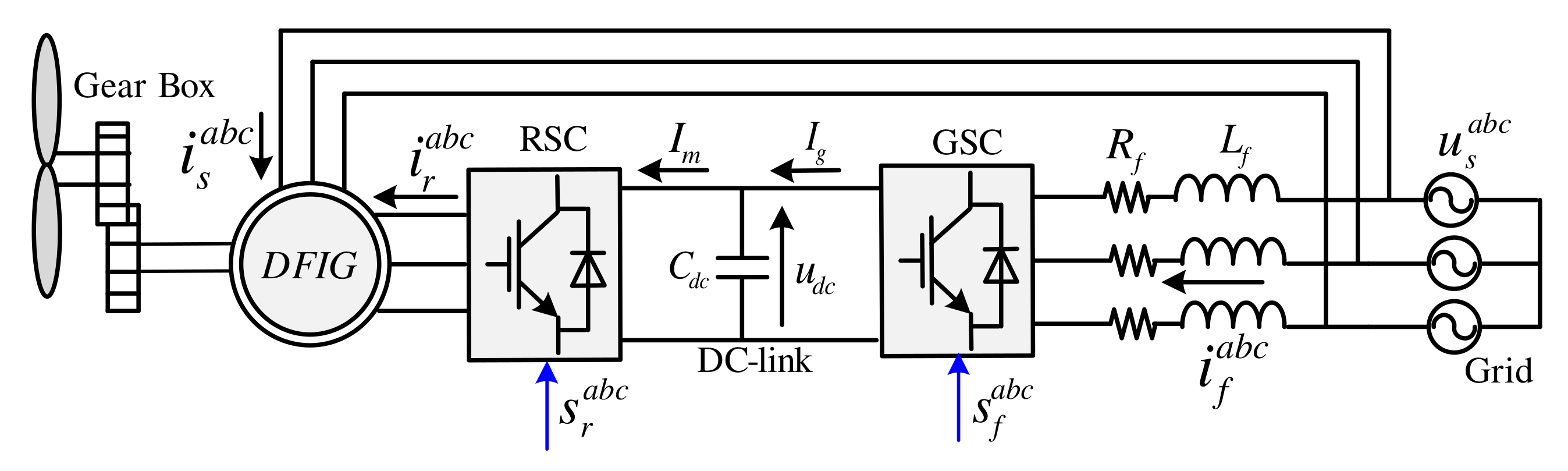
The block diagram of the wind energy system with doubly-fed induction generator is shown Figure 1. In order to allow the variable-speed operation of the wind turbine, the rotor of the DFIG is tied with the grid via a reduced-scale back-to-back (BtB) power converter, which consist of grid-side converter (GSC), Dc-link, and and rotor side converter (RSC). In this study, the control of the RSC is only considered.
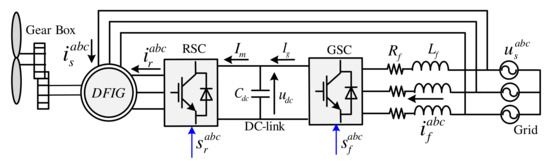
Figure 1.
Block diagram of the wind energy system with doubly-fed induction generator.
The stator and rotor voltages of the DFIG in the three-phase system, i.e., reference frame, are expressed as [7]
and
In the above equations, the stator and rotor fluxes are written as
and
In the above equations, , , , , , and are the stator and rotor voltages of the DFIG. The stator and rotor currents are , , , , , and . , , , , , and are the stator and rotor fluxes of the DFIG. and are the stator and rotor resistances, respectively. , , and are the stator, rotor and mutual inductances.
Using Clarke transformation [7], the stator and rotor voltages of the DFIG can be expressed in the reference frame as
and
In (6), is the electrical angular speed of the rotor and is computed as , where is the number of pole pairs and is the mechanical angular speed of the rotor.
Usually, the control system of the DFIG is designed in the rotating reference frame. Accordingly, by the help of Park transformation, the stator and rotor voltages of the DFIG can be written in the reference frame as
and
The stator and rotor fluxes of the DFIG can be written in the frame as
and
Based on the above equations and by doing some mathematical calculations, the rotor voltage of the DFIG can be expressed as [7]
where . Equation (11) is written in the continuous-time domain, which is not suitable to implement the controller on a digital signal processor (DSP). By the help of forward Euler method, the form of Equation (11) in the discrete-time domain is
In (12), the sampling time is and k is the current sample.
3. Conventional Deadbeat Predictive Control
In the mathematical model of the DFIG, the values of , , , , and are usually measured in the laboratory or obtained from the data-sheet of the machine. Subsequently, those parameters are assumed constant in the design of the conventional DBPC method. Taking the one sample delay into consideration [31], the reference voltages is calculated based on the reference currents and model of the DFIG as follows [7]
In (13), , , , , , , , and can be computed using Lagrange extrapolation as
Based on Equations (13) and (15), the computation of the reference voltage by the conventional DBPC is extensively dependent on the parameters of the DFIG. Therefore, the sensitivity of the conventional DBPC is high. In Figure 2, the traditional DBPC for DFIGs is shown.
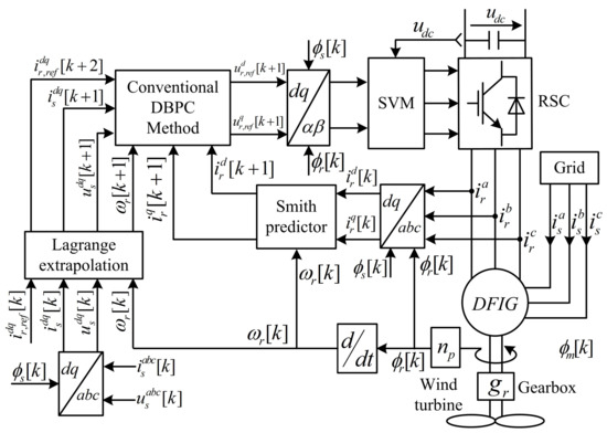
Figure 2.
Blcok diagram of the conventional deadbeat predictive control strategy for DFIGs.
4. Proposed Deadbeat Predictive Control
The main difference between the conventional DBPC and proposed one is taking into consideration the effect of parameters mismatches and any un-modeled dynamics, see Figure 3. Therefore, by considering this issue, Equation (12) is re-written as
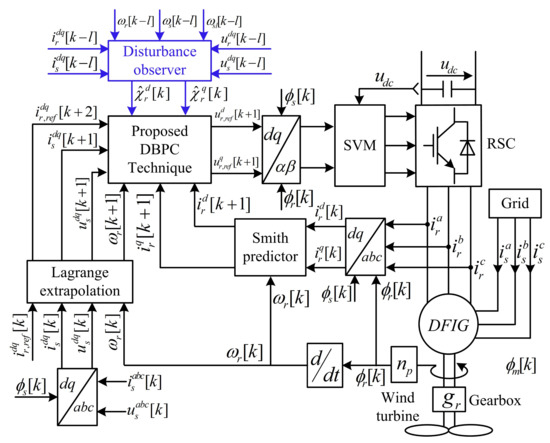
Figure 3.
Blcok diagram of the proposed deadbeat predictive control strategy for DFIGs.
In (16), , , , , and represent the variations of the parameters of the DFIG. The un-modeled dynamics for the d- and q-axis are represented by and , respectively. Equation (16) can be written as
where and are the total disturbances due to mismatches in the DFIG parameters and any un-modeled dynamics. They can be expressed as
It can be obsereved from Equation (18) that the values of and can not be obtained because the values of , , , , and are unknowns and can not be measured. Therefore, those values must be estimated. Accordingly, the proposed DBPC calculates the reference voltages as follows
In (19), and are the estimated values of the total disturbances due to parameter mismatches and any un-modeled dynamics. Those values are estimated by using the concept of time delay control approach [31], where it is assumed that the values of and at the sample k are almost equal to those at the sample ( is integer bigger than zero) as
Subsequently, and are estimated from (17) as
Finally, by using Lagrange extrapolation we can get the values at the sample . It can be observed from Equation (21) that the proposed observer uses the stator/rotor voltages/currents and the rotor speed to estimate the disturbances. Those signals must be measured for the control system, i.e., no additional signals are required for the proposed observer, i.e., no additional hardware or cost.
5. Results and Discussion
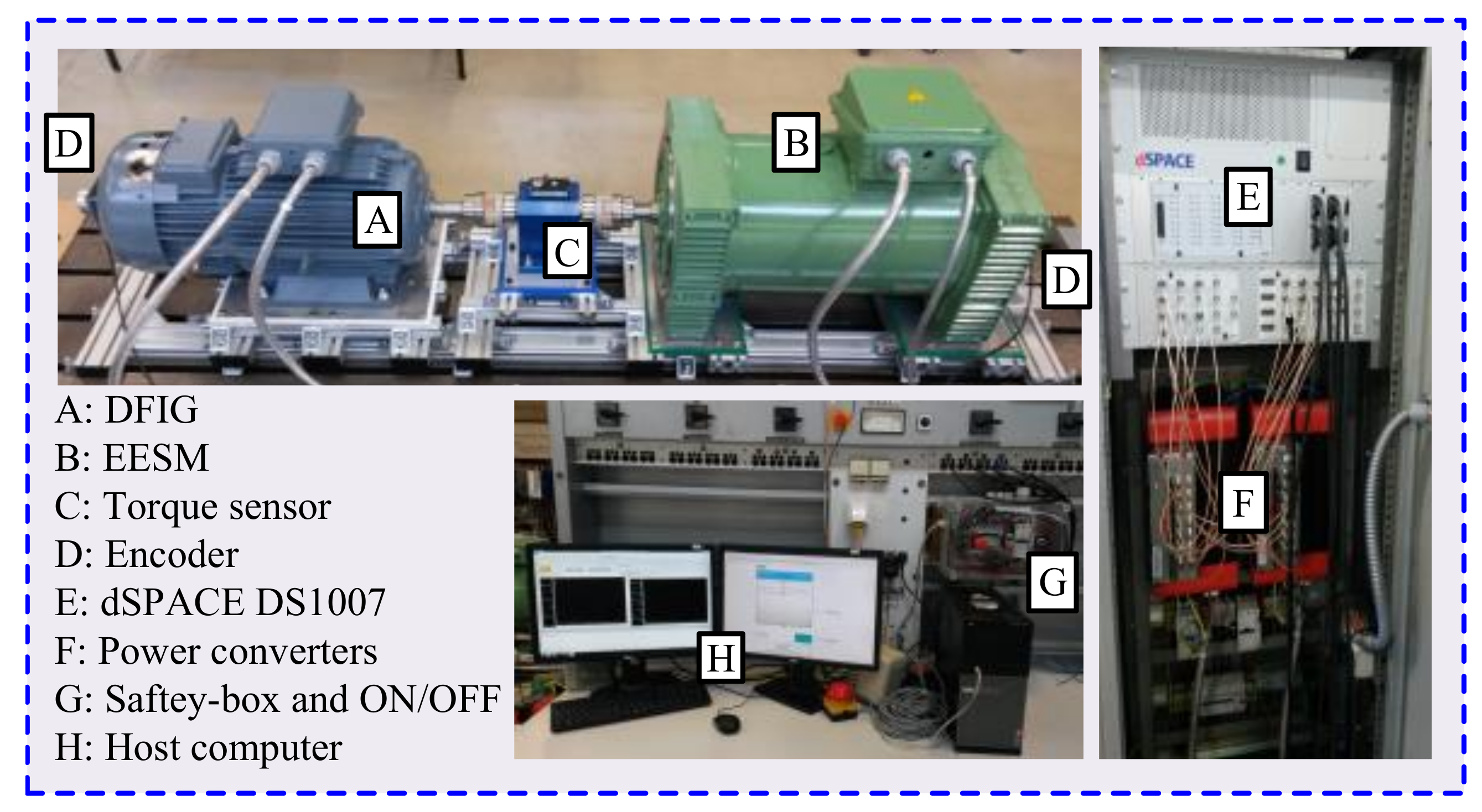
In order to validate the proposed DBPC technique, the test bench illustrated in Figure 4 is constructed in the laboratory. The nominal power of the DFIG is kW and its parameters are given in Table 1. Unfortunately, no wind turbine emulator is available in the laboratory. Hence, we use a kW electrical-excited synchronous machine (EESM) to control the rotational speed of the rotor. The available real-time system in the laboratory is a dSPACE DS1007 with following boards:
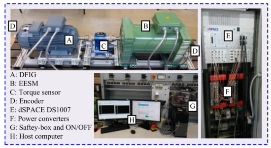
Figure 4.
The constructed test bench to validate the suggested DBPC technique.

Table 1.
Parameters of the utilized DFIG.
- DS3002 incremental encoder board.
- DS2004 analog to digital converter (A/D) board.
- DS5101 pulse-width-modulation board.
The stator of the DFIG is connected to a fixed AC voltage source and the rotor is connected to a bi-directional power converter manufactured by SEW-Eurodrive GmbH & Co KG. In reality, the rated power of this power converter is approximately of the DFIG nominal power. Unfortunately, small power converters are not available in the laboratory and the available one have a rated power of kW, which is used in the constructed test-bench. In this power converter, IGBT switches are used and the switching frequency range is between kHz and kHz. Accordingly, a switching frequency of kHz is selected in this work.
In order to implement the proposed and traditional control methods, current and voltage measurement boards are designed to measure the stator and rotor currents and voltages. In those measurement boards, filters are included to eliminate the switching noise.
5.1. Performance with the Measured Parameters of the DFIG
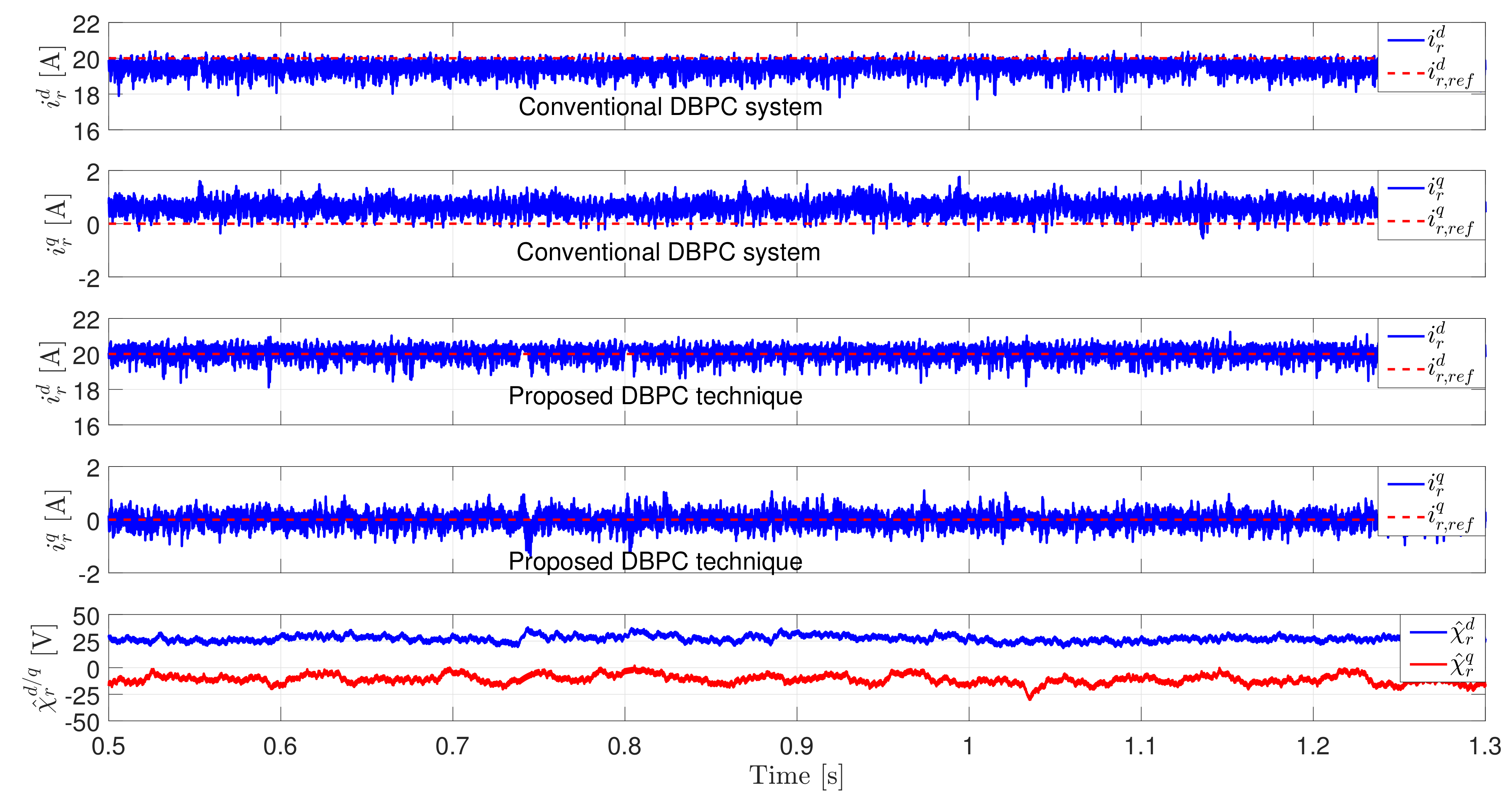
The first experiment is performed by using the measured parameters of the DFIG, i.e., in the software model of the proposed and conventional control techniques, the values of the used parameters are the measured ones, i.e., , , , , and (the subscript means measured). The value of the rotational mechanical speed is set to by the control system of the EESM. The reference values of the d- and q-axis rotor currents of the DFIG are selected and , respectively, where the d-axis current controls the generated active power and the q-axis current controls the reactive power of the stator. These active and reactive power are injected to the grid and can be used to support the frequency and voltage of the grid. However, this effect can be not illustrated in the constructed test-bench due to the use of a constant AC voltage source not a grid.
According to Figure 5, the measured d- and q-axis rotor currents of the DFIG are tracking the reference values with almost a zero steady-state error using the proposed DBPC technique with disturbance observer, while the steady-state error using the conventional DBPC strategy is higher than zero. The absolute steady-state errors (ASSEs) of the d- and q-axis currents are given in Table 2. By using the conventional DBPC strategy, it can be clearly observed that the measured d- and q-axis rotor currents are slightly deviated from the reference values. This observation confirm that the measured values of the DFIG parameters are varying and not constant. Therefore, by including the estimated entire disturbance (see Figure 5 bottom) to the reference voltage calculation, the control performance is better.

Figure 5.
Experimental results with the nominal parameters of the DFIG (from top to bottom): Measured/reference d-axis rotor current using the conventional DBPC, measured/reference q-axis rotor current using the conventional DBPC, Measured/reference d-axis rotor current using the proposed DBPC, Measured/reference q-axis rotor current using the proposed DBPC, and estimated total disturbance for d- and q-axis.
Table 2.
ASSEs of the conventional and proposed DBPC techniques.
5.2. Performance with Mismatches in the Stator and Rotor Resistances
In the second experiment, the values of the stator and rotor resistances are reduced to of their measured values (i.e., and ) and the values of the inductances are set to the measured values, i.e., , , and . The value of the rotational mechanical speed is set to by the control system of the EESM. The reference values of the d- and q-axis rotor currents of the DFIG are selected and , respectively. Based on Figure 6, the deviations of the measured rotor currents from the reference values using the conventional DBPC is increased than the case of using the measured parameters (i.e., Figure 5), in particularly in the d-axis (see the ASSEs of the d- and q-axis currents in Table 2). In contrast to that, the measured rotor currents are perfectly tracking the reference values using the proposed DBPC technique. This is due to inclusion of illustrated in Figure 6 to the computation of the actuation voltage.

Figure 6.
Experimental results with mismatches in the stator and rotor resistances (from top to bottom): Measured/reference d-axis rotor current using the conventional DBPC, measured/reference q-axis rotor current using the conventional DBPC, Measured/reference d-axis rotor current using the proposed DBPC, Measured/reference q-axis rotor current using the proposed DBPC, and estimated total disturbance for d- and q-axis.
5.3. Performance with Mismatches in the Inductances
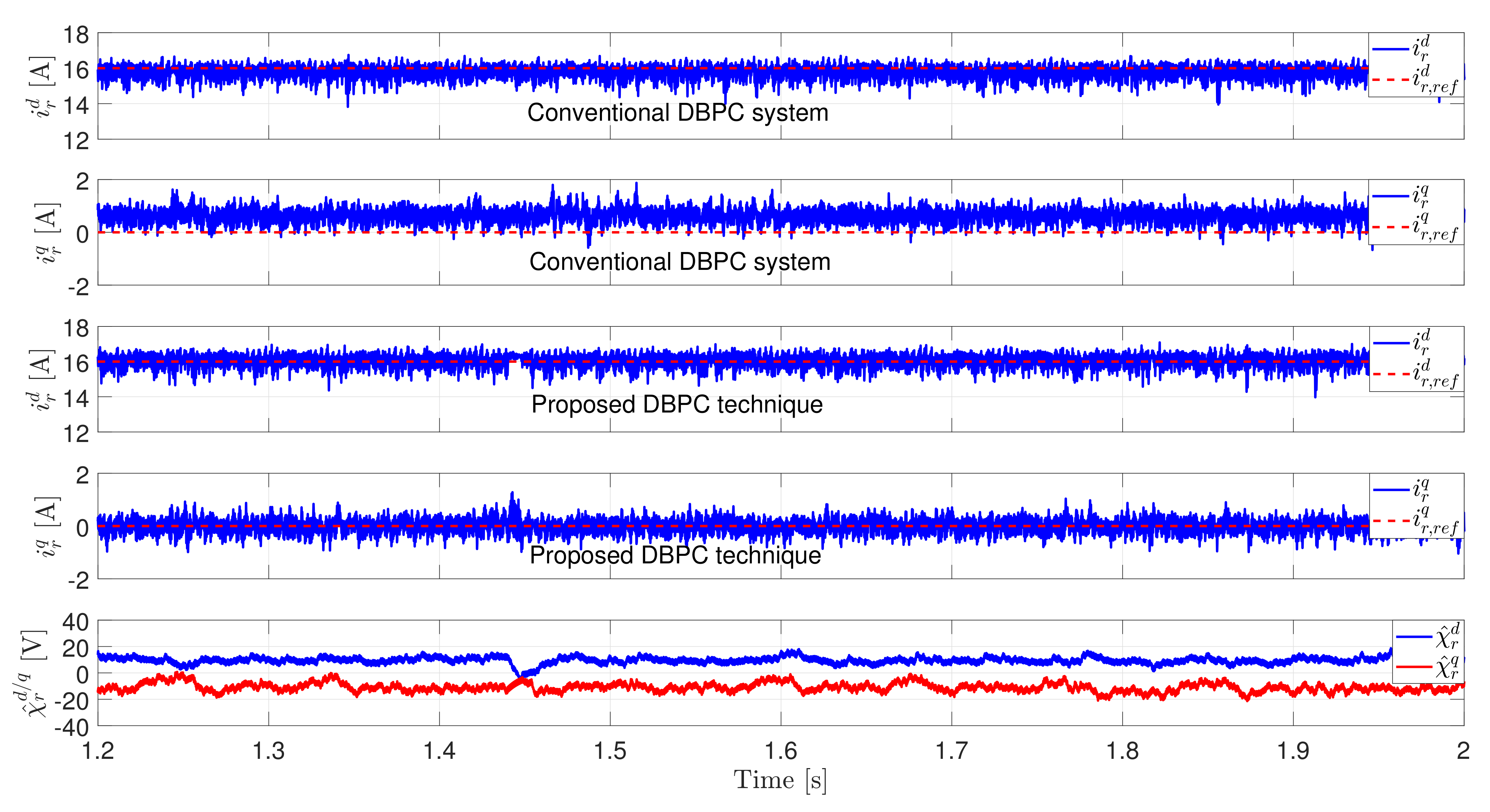
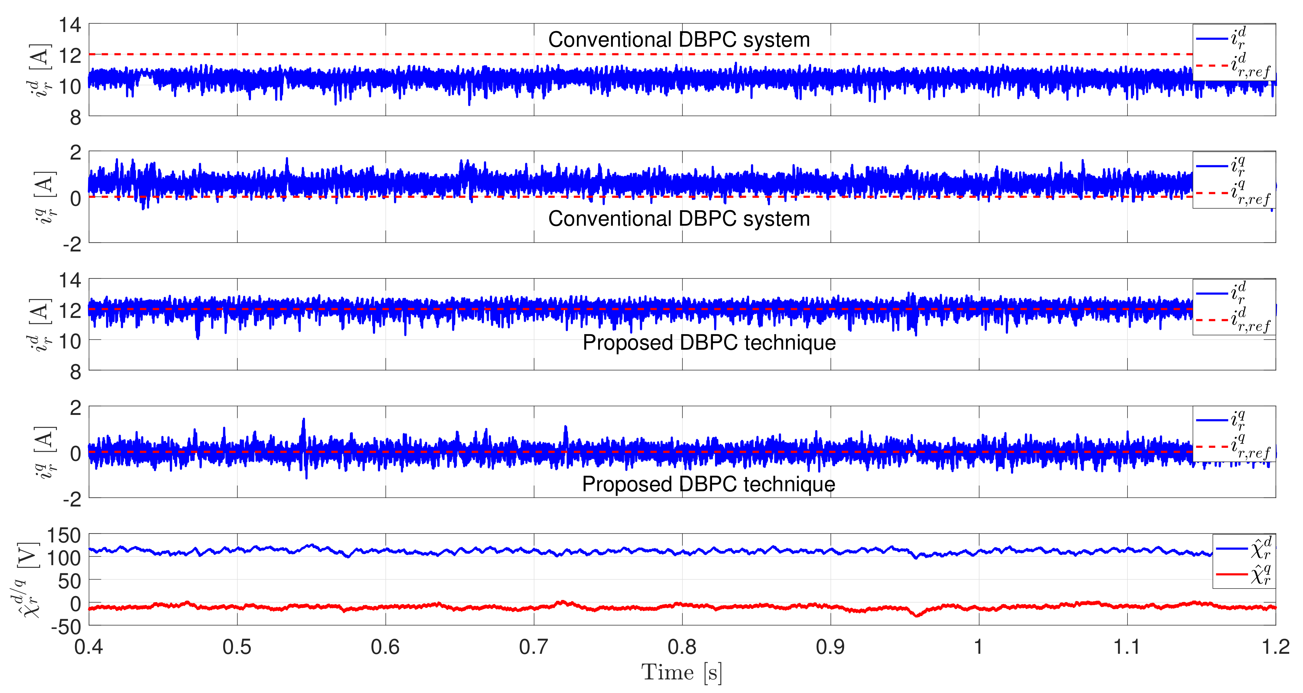
In the last experiment, the values of the stator/rotor/mutual inductances are increased to of their measured values, i.e., , , and . The values of the stator and rotor resistances are set to the measured values, i.e., and . The value of the rotational mechanical speed is set to by the control system of the EESM. The reference values of the d- and q-axis rotor currents of the DFIG are selected and , respectively. It can by seen in Figure 7 that by using the conventional DBPC system the measured d- and q-axis rotor currents largely deviated from their reference values, in particularly the d-axis current (see the ASSEs of the d- and q-axis currents in Table 2). This is not the case by using the proposed DBPC technique, where the measured d- and q-axis rotor currents are tracking the reference values with almost a zero steady-state error. Thanks to the proposed simple disturbance observer.
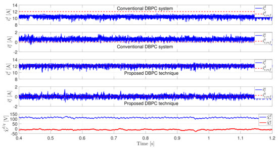
Figure 7.
Experimental results with mismatches in the inductances (from top to bottom): Measured/reference d-axis rotor current using the conventional DBPC, measured/reference q-axis rotor current using the conventional DBPC, Measured/reference d-axis rotor current using the proposed DBPC, Measured/reference q-axis rotor current using the proposed DBPC, and estimated total disturbance for d- and q-axis.
6. Conclusions
In this paper, a low sensitivity deadbeat predictive control (DBPC) technique is proposed for doubly-fed induction generators (DFIGs) utilized in wind turbine applications. In order to compensate the effect of parameters variations of the DFIG and any un-modeled dynamics, a simple observer is presented to estimate the total disturbance due to parameters mismatches and un-modeled dynamics. Subsequently, this total disturbance is included in the calculation of the actuation voltage. The proposed DBPC with disturbance observer is implemented in the laboratory. The results illustrated that the proposed DBPC is highly robust to any parameters mismatches and un-modeled dynamics, while the conventional DBPC is very sensitive.
For future work, the effects of factors like change of the grid impedance, errors of sensors, and frequency fluctuations of the grid will be considered.
Author Contributions
M.A.: Design/implementation of the proposed control technique; writing of the whole manuscript, and drawing of the figures. C.H.: Providing the test-bench used to implement the proposed control strategy and review of the manuscript. R.K. and J.R.: Review of the manuscript, guidance, and suggestions. All authors have read and agreed to the published version of the manuscript.
Funding
This research received no external funding.
Institutional Review Board Statement
Not applicable.
Informed Consent Statement
Not applicable.
Data Availability Statement
Not applicable.
Acknowledgments
J. Rodriguez acknowledges the support of ANID through projects FB0008, ACT192013 and 1210208.
Conflicts of Interest
The authors declare no conflict of interest.
References
- Bose, B.K. Power Electronics in Renewable Energy Systems and Smart Grid: Technology and Applications; Wiley-IEEE Press: Hoboken, NJ, USA, 2019. [Google Scholar]
- Shourangiz-Haghighi, A.; Diazd, M.; Zhang, Y.; Li, J.; Yuan, Y.; Faraji, R.; Ding, L.; Guerrero, J.M. Developing More Efficient Wind Turbines: A Survey of Control Challenges and Opportunities. IEEE Ind. Electron. Mag. 2020, 14, 53–64. [Google Scholar] [CrossRef]
- Ahmed, S.D.; Al-Ismail, F.S.M.; Shafiullah, M.; Al-Sulaiman, F.A.; El-Amin, I.M. Grid Integration Challenges of Wind Energy: A Review. IEEE Access 2020, 8, 10857–10878. [Google Scholar] [CrossRef]
- Tang, X.; Hu, Y.; Chen, Z.; You, G. Flexibility Evaluation Method of Power Systems with High Proportion Renewable Energy Based on Typical Operation Scenarios. Electronics 2020, 9, 627. [Google Scholar] [CrossRef]
- Baroudi, J.A.; Dinavahi, V.; Knight, A.M. A review of power converter topologies for wind generators. Renew. Energy 2007, 32, 2369–2385. [Google Scholar] [CrossRef]
- Tohidi, S.; Behnam, M.I. A comprehensive review of low voltage ride through of doubly fed induction wind generators. Renew. Sustain. Energy Rev. 2016, 57, 412–419. [Google Scholar] [CrossRef]
- Abdelrahem, M. Predictive Control and Finite-Set Observers for Variable-Speed Wind Generators. Ph.D. Thesis, Technical University of Munich, Munich, Germany, 2020. Available online: https://mediatum.ub.tum.de/1520001 (accessed on 10 May 2021).
- Abad, G.; López, J.; Rodríguez, M.; Marroyo, L.; Iwanski, G. Doubly Fed Induction Machine: Modeling and Control for Wind Energy Generation Applications; Wiley-IEEE Press: Hoboken, NJ, USA, 2011. [Google Scholar]
- Abdelrahem, M.; Hackl, C.M.; Kennel, R. Limited-Position Set Model-Reference Adaptive Observer for Control of DFIGs without Mechanical Sensors. Machines 2020, 8, 72. [Google Scholar] [CrossRef]
- Abdelrahem, M.; Hackl, C.M.; Rodríguez, J.; Kennel, R. Model Reference Adaptive System with Finite-Set for Encoderless Control of PMSGs in Micro-Grid Systems. Energies 2020, 13, 4844. [Google Scholar] [CrossRef]
- Sadeghian, O.; Tohidi, S.; Mohammadi-Ivatloo, B.; Mohammadi, F. A Comprehensive Review on Brushless Doubly-Fed Reluctance Machine. Sustainability 2021, 13, 842. [Google Scholar] [CrossRef]
- Cárdenas, R.; Peña, R.; Alepuz, S.; Asher, G. Overview of Control Systems for the Operation of DFIGs in Wind Energy Applications. IEEE Trans. Ind. Electron. 2013, 60, 2776–2798. [Google Scholar] [CrossRef]
- Abdelrahem, M.; Kennel, R. Efficient Direct Model Predictive Control for Doubly-Fed Induction Generators. Electr. Power Compon. Syst. 2017, 45, 574–587. [Google Scholar] [CrossRef]
- Eltamaly, A.M.; Al-Saud, M.; Sayed, K.; Abo-Khalil, A.G. Sensorless Active and Reactive Control for DFIG Wind Turbines Using Opposition-Based Learning Technique. Sustainability 2020, 12, 3583. [Google Scholar] [CrossRef]
- Liu, X.; Kong, X. Nonlinear Model Predictive Control for DFIG-Based Wind Power Generation. IEEE Trans. Autom. Sci. Eng. 2014, 11, 1046–1055. [Google Scholar] [CrossRef]
- Hammoud, I.; Xu, K.; Hentzelt, S.; Oehlschlaegel, T.; Kennel, R. On Offset-Free Continuous Model Predictive Current Control of Permanent Magnet Synchronous Motors. IFAC-Pap. Online 2020, 53, 6662–6669. [Google Scholar] [CrossRef]
- Filho, A.J.S.; Filho, E.R. Model-based predictive control applied to the doubly-fed induction generator direct power control. IEEE Trans. Sustain. Energy 2012, 3, 398–406. [Google Scholar] [CrossRef]
- Vazquez, S.; Rodriguez, J.; Rivera, M.; Franquelo, L.G.; Norambuena, M. Model Predictive Control for Power Converters and Drives: Advances and Trends. IEEE Trans. Ind. Electron. 2017, 64, 935–947. [Google Scholar] [CrossRef] [Green Version]
- Sguarezi Filho, A.J.; de Oliveira, A.L.; Rodrigues, L.L.; Costa, E.C.M.; Jacomini, R.V. A Robust Finite Control Set Applied to the DFIG Power Control. IEEE J. Emerg. Sel. Top. Power Electron. 2018, 6, 1692–1698. [Google Scholar] [CrossRef]
- Xu, L.; Zhi, D.; Williams, B.W. Predictive Current Control of Doubly Fed Induction Generators. IEEE Trans. Ind. Electron. 2009, 56, 4143–4153. [Google Scholar]
- Zhi, D.; Xu, L.; Williams, B.W. Model-Based Predictive Direct Power Control of Doubly Fed Induction Generators. IEEE Trans. Power Electron. 2010, 25, 341–351. [Google Scholar]
- Abdelrahem, M.; Hackl, C.; Kennel, R. Application of Extended Kalman Filter to Parameter Estimation of Doubly-Fed Induction Generators in Variable-Speed Wind Turbine Systems. In Proceedings of the 5th International Conference on Clean Electrical Power (ICCEP), Taormina, Italy, 16–18 June 2015; pp. 226–233. [Google Scholar]
- Amiri, N.; Madani, S.M.; Lipo, T.A.; Zarchi, H.A. An Improved Direct Decoupled Power Control of Doubly Fed Induction Machine Without Rotor Position Sensor and With Robustness to Parameter Variation. IEEE Trans. Energy Convers. 2012, 27, 873–884. [Google Scholar] [CrossRef]
- Bhattarai, R.; Gurung, N.; Ghosh, S.; Kamalasadan, S. Parametrically Robust Dynamic Speed Estimation Based Control for Doubly Fed Induction Generator. IEEE Trans. Ind. Appl. 2018, 54, 6529–6542. [Google Scholar] [CrossRef]
- Zhang, Y.; Jiang, T.; Jiao, J.; Xu, W. Model-free predictive current control of doubly fed induction generator. In Proceedings of the 2019 22nd International Conference on Electrical Machines and Systems (ICEMS), Harbin, China, 11–14 August 2019; pp. 1–5. [Google Scholar]
- Zhang, Y.; Jiang, T.; Jiao, J. Model-Free Predictive Current Control of a DFIG Using an Ultra-Local Model for Grid Synchronization and Power Regulation. IEEE Trans. Energy Convers. 2020, 35, 2269–2280. [Google Scholar] [CrossRef]
- Errouissi, R.; Al-Durra, A.; Muyeen, S.M.; Leng, S.; Blaabjerg, F. Offset-free direct power control of DFIG under continuous-time model predictive control. IEEE Trans. Power Electron. 2017, 32, 2265–2277. [Google Scholar] [CrossRef]
- Abdelrahem, M.; Hackl, C.; Kennel, R.; Rodriguez, J. Efficient Direct Model Predictive Control with Discrete Time Integral Action for PMSGs. IEEE Trans. Energy Convers. 2019, 34, 1063–1072. [Google Scholar] [CrossRef]
- Guo, L.; Wang, D.; Diao, L.; Peng, Z. Direct voltage control of standalone DFIG under asymmetric loads based on non-singular terminal sliding mode control and improved extended state observer. IET Electr. Power Appl. 2019, 13, 958–968. [Google Scholar] [CrossRef]
- Tang, P.; Dai, Y.; Li, Z. Unified Predictive Current Control of PMSMs with Parameter Uncertainty. Electronics 2019, 8, 1534. [Google Scholar] [CrossRef] [Green Version]
- Abdelrahem, M.; Hackl, C.; Zhang, Z.; Kennel, R. Robust Predictive Control for Direct-Driven Surface-Mounted Permanent-Magnet Synchronous Generators Without Mechanical Sensors. IEEE Trans. Energy Convers. 2018, 33, 179–189. [Google Scholar] [CrossRef]


Publisher’s Note: MDPI stays neutral with regard to jurisdictional claims in published maps and institutional affiliations. |
© 2021 by the authors. Licensee MDPI, Basel, Switzerland. This article is an open access article distributed under the terms and conditions of the Creative Commons Attribution (CC BY) license (https://creativecommons.org/licenses/by/4.0/).