Abstract
Automotive radar interference mitigation is expected to be inherent in all future ADAS and AD vehicles. Joint radar communications is a candidate technology for removing this interference by coordinating radar sensing through communication. Coordination of radars requires strict time synchronization among vehicles, and our formerly proposed protocol (RadChat) achieves this by a precise absolute time, provided by GPS clocks of vehicles. However, interference might appear if synchronization among vehicles is lost in case GPS is spoofed, satellites are blocked over short intervals, or GPS is restarted/updated. Here we present a synchronization-free version of RadChat (Sync-free RadChat), which relies on using the relative time for radar coordination, eliminating the dependency on the absolute time provided by GPS. Simulation results obtained for various use cases show that Sync-free RadChat is able to mitigate interference without degrading the radar performance.
1. Introduction
Automotive radar interference occurs when another radar signal interferes with one’s own radar reflection. Joint radar communications (RadCom) offers spectrally efficient and safe mutual radar interference mitigation. Among the various RadCom techniques, those based on time/frequency resource-sharing among radar and communications [1,2] are especially simple to implement, since they rely on switching to communication mode whenever the radar becomes idle, and require a combination of two already existing chipsets by a controller. However, to achieve coordination among vehicles, radars mounted on different vehicles need to be synchronized with microsecond-level precision.
Microsecond-level synchronization among vehicles in vehicular ad hoc networks (VANET) are highly dynamic in nature due to high relative speeds up to 300 km/h and frequent vehicle insertions and deletions, achievable only through GNSS systems. GNSS satellites periodically broadcast packets, by which each vehicle solves for its position and clock bias [3] through triangulation. GPS satellites generally include 3–4 atomic clocks with less than 10 parts per million (ppm) clock drifts, so that a 10 Hz update rate leads to a clock drift of 1 s or less for a vehicle, under uninterrupted connection to at least four satellites.
However, the synchronization between vehicles and GNSS satellites deteriorates if vehicles lose connection with satellites while being inside a tunnel or an urban environment with a canyon effect, or the GPS is updated/restarted [4]. In such cases, drifts experienced by vehicles are different due to different clock hardwares, batteries and temperatures [3], resulting in unsynchronized vehicles. Vehicles generally have clocks with drift rates of 10–50 ppm, resulting in drifts of about 10–50 s every second and 0.6–3 ms every minute in the case of a signal outage. Moreover, the restart/update of the GPS takes additional time, usually requiring a few seconds to get an accurate fix from the satellites, leading to 10–30 s/s additional delays. GPS spoofing, an attacker imitating GPS signals, is another risk for losing GNSS-based synchronization with larger discrepancies.
Loss of synchronization among vehicles can severely affect RadCom-based solutions for interference mitigation. Vehicles become more vulnerable to mutual radar interferences inside a tunnel or in a city center with a canyon effect, as the duration of the GNSS signal outage increases. Likewise, RadCom-based mutual radar interference solutions might become useless under a GPS spoofing attack as the duration of exposure to the attack increases due to the loss of sychronization among vehicles.
There are synchronization protocols, resilient to GPS spoofing or GPS signal outages proposed for VANETs [5,6,7,8,9,10]. A clock synchronization method, which extracts information from the neighbors’ Basic Safety Messages (BSM) of DSRC, is shown to achieve a predefined 0.5 s timing offset under GPS spoofing [5]. A four-way communication protocol for IEEE802.11p achieves about 0.3 ms offset [6]. A time synchronization for fog-based VANETs is shown to achieve a 20 ms timing offset [7], and another method based on clustered topology is shown to achieve 5–45 ms clock offsets [8]. Unfortunately, these synchronization protocols are far from achieving the s-level synchronization needed for mitigation of automotive radar interference.
In this paper, we propose a RadCom-based interference mitigation protocol that does not rely on GNSS or such VANET synchronization protocols; but is designed specifically to eliminate the need for synchronization. The proposed sychronization-free automotive radar interference mitigation protocol (Sync-free RadChat) is a modified version of our former proposed RadChat protocol [1] and removes the dependency on a GPS receiver mitigating an automotive radar interference, even while driving through tunnels or urban canyons, when vehicles become unsynchronized due to unequal clock drifts.
The remainder of this paper is organized as follows. After a brief introduction of an FMCW-based radar and communication cooperation system model and propagation channel model in Section 2, the Sync-free RadChat framework is described in Section 3 including a background on the RadChat protocol. The mutual radar interference mitigation performance of Sync-free RadChat is investigated and results are presented in Section 4. A list of notations used in this article is presented in Table 1 for convenience.

Table 1.
List of Notations.
2. System Model and Assumptions
2.1. Radar Communications Model
All automotive radars are assumed to be replaced with radar communication units (RCU), which have an additional communication functionality together with radar sensing on a single hardware. An RCU hardware is similar to an automotive radar, except that it has a modulator and demodulator added for communication purposes. An RCU has a common antenna array and ADC, which are interchangeably used among radar and communication functions. All RCUs mounted on the same vehicle are assumed to be controlled via a central unit.
All vehicles are assumed to use FMCW-type radars. We assume front-end and back-end radars to be long-range radars (LRR), whereas corner radars are medium-range radars (MRR) and side radars are short-range radars (SRR). The whole radar bandwidth is assumed to be divided among these categories so that LRRs, MRRs, and SRRs use bandwidths of , , and , respectively. This ensures that MRRs are allocated a higher bandwidth in order to achieve a better-range resolution compared to LRRs, as it is implemented in practice by the automotive manufacturers [11]. All radars using the same portion of bandwidth are assumed to use the same bandwidth ( if LRR, if MRR, if SRR), same chirp duration T, and same frame time , comprising N chirps per frame. Note that T and N might be designed so as to be different for long-, medium-, or short-range radars. For a simplified clarification, we use the general notations T and N, as well as for the rest of the text.
Jointly using the ADC by radar and communications upper-bounds the communication band , with the ADC bandwidth, that is, . The ADC bandwidth may be larger than the radar bandwidth of interest , which is determined by the low-pass filter cut-off frequency for processing the intended radar reflections. The ADC has been the hardware that limits the radar range, but we might be interested in even a smaller range in order limit and filter out the mutual radar interference signals coming from very far away. gives us control over the interference range.
The processed radar signals will then have a maximum delay for (intended) radar reflections , where is the radar sensing range and c is the speed of light. Note that is the round-trip-delay of a radar reflection, whereas it is also the maximum propagation delay for a radar interference signal. Mutual radar interference signals emitted more than earlier are filtered out at the radar signal processing stage.
Automotive interference mitigation is a safety-critical function. Various research results that have involved different automotive manufacturers (including Volvo, SAAB, Fiat-Chrysler, Ford, and General Motors) and suppliers (Veoneer, Bosch, Denso, Magna, NPX, Valeo, and ZF/TRW) have revealed that interference mitigation can be accomplished only through standardized solutions for all vehicles in the future [11,12]. This imposes all radars or RCUs to agree on the set of waveforms to be used. Sync-free RadChat can then be used to decide which waveform to be used at which time, in order to reduce interference while still meeting radar requirements.
2.2. Propagation Channel Model
We use a geometry-based deterministic vehicular channel model assuming operation in the high-frequency mmWave bands [13,14]. Both radar and communication signals are assumed to propagate either through a LoS path if one exists, or through ground-reflections due to the high reflectivity of the asphalt for mmWave bands. The asphalt acts as a reflector rather than a scatterer for the considered mm-Wave frequencies, since the comparable size of asphalt particles (at most 1.27 cm [15]) is much larger than the wavelength (3.7–4 mm). Hence, a radar signal reflection is received over both a LoS radar return with range (with signal-to-noise ratio ) and a ground-reflected radar return (with range and ). Likewise, a radar-to-radar interference is received over two paths: LoS (, ) and the ground-reflected path (, ). Finally, communication signals travel over LoS (, ) and ground-reflected paths (, ). Figure 1 illustrates the six different types of signals considered in this article.
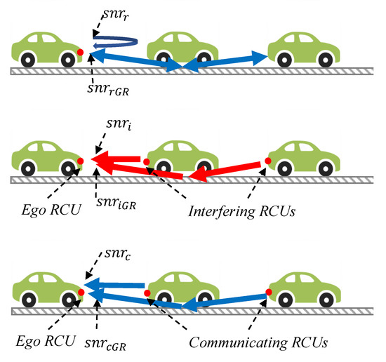
Figure 1.
Illustration of radar, radar interference, and communication signals. The signal-to-noise ratios at an ego RCU for these signals are , , and , respectively. In this article, we also consider the ground-reflected signals for radar, radar interference, and communication, where the signal-to-noise ratios perceived at the ego RCU are , , and , respectively.
We assume that both radar and communication signals use the same antennas, resulting in a similar field of beamwidths. However, the radar and communication transmit powers, where and might be different, resulting in different communication and radar ranges. The FMCW radar processing gains , which is equal to the product of numbers of FMCW chirps and samples per chirp. Assuming Friis free space propagation and radar equations [16], the signal ranges and signal-to-noise ratios () perceived at a RCU are calculated as [17]:
where is the radar processing gain, is the multiplication of transmit and receiver antenna gains (with an assumption that it is equal for LoS and ground-reflected signals for the narrow-beam transmissions), is the radar cross-section of the target, is the reflection coefficient, and are the wavelengths of radar and communication signals, respectively; and are thermal noise powers for radar and communication reception.
3. Sync-Free Radchat: Protocol Description
Sync-free RadChat is a totally decentralized interference-mitigation protocol, which coordinates radar transmissions by sharing relative times. It is an advanced version of our formerly proposed GPS clock-dependent RadChat protocol [1], in the sense that it mitigates interference even when any vehicle is unsynchronized with the rest of the vehicles in the VANET (with even a few microseconds of timing offsets), due to GPS signal outage (tunnel, urban canyon effect, restart/update) or GPS spoofing. Sync-free RadChat is not a complement to RadChat, it is a replacement for RadChat. Hence, we propose all radars in a VANET to be replaced by RCUs that all implement the Sync-free RadChat protocol for a GPS-independent interference mitigation functionality. After a brief introduction of RadChat protocol, we describe the Sync-free RadChat protocol in this section.
3.1. Background: Basics of the RadChat Protocol
RadChat is a distributed cooperative radar communications protocol, especially designed to mitigate interfence. By RadChat, radar sensing of various RCUs are coordinated via a communication control channel. RCUs switch to communication functionality whenever FMCW radar chirps are sent and the radar sensing is idle over the period . Radar and communication use disjointed allocated bandwidths and .
By RadChat, the whole radar bandwidth can be divided to chunks in the frequency domain, as shown in Figure 2 in order to allow scheduling of different types of automotive radars, such as medium-range radars to a larger bandwidth, and long-range radars to a smaller bandwidth in order to meet the various distance resolution requirements. In this article, we assume that is used for only one type of radar and is not divided in frequency for simplicity.
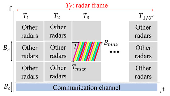
Figure 2.
Time-frequency resource allocation for radar transmissions of different RCUs. FMCW chirp sequences of different RCUs are denoted by different colors, which occupy a portion of the radar band during the time slot . Other radar transmissions are scheduled to other frequency bands within and time slots, whereas communication signals are transmitted over .
RadChat divides the time resource into time slots denoted by for , where is the modified radar duty cycle with one more chirp time added as a buffer to each time slot.
Radars of different RCUs are scheduled to use both the idle time in between radar chirp sequences and the idle time within radar chirps, as shown in Figure 2. In this example, several time-shifted radars are scheduled to occupy a portion of the radar band during the time slot , where FMCW radar chirp sequences sent by different RCUs are denoted by different colors. It is possible to schedule other radar transmissions to other frequency bands and time slots, whereas communication signals used for coordination are transmitted over .
A connectionless best-effort service is provided for communication over the bandwidth through carrier sense multiple access with collision avoidance (CSMA/CA) with retransmissions and binary exponential backoff. If the radar FMCW chirp sequence is sent at time slot , each RCU broadcasts an unacknowledged communication packet in a prior time slot , which includes the radar chirp starting time and frequency. Other RCUs which receive this broadcast packet select a radar chirp starting time and frequency in non-overlapping frequency bands and vulnerable periods. The vulnerable period V is a key concept in RadChat, and is defined as the duration over which other RCUs should not transmit their radar signals. The vulnerable period of RadChat over a chirp is calculated by summation of the round-trip-delay of the radar signal and the propagation delay of the furthest away possible communicating interferer :
Since RadChat is able to mitigate interferences coming from the furthest away RCU only if it is within communication range, becomes the ratio of the minimum of the communication range () or furthest away interferer distance () to the radar round-trip distance ():
RadChat converges and interference-free radar sensing is provided after time when all vehicle RCUs in a vehicular network: (i) use the same time notion, which is called as the identity (ID), and (ii) use disjoint time-frequency slots for radar sensing, called the SlotIndex (SI). The RadChat protocol is described simply in Figure 3 for the use case of two approaching vehicles, where interference blinds the victim vehicle. This is a safety-critical scenario, since a direct LoS interference has a much stronger signal than a radar reflection, which causes the victim’s radar to be useless in detecting any vulnerable road users [18]. Since the victim radar’s ADC filters any radar reflections and interferences within the bandwidth , mutual radar interference becomes apparent as soon as the two vehicles approach, so that the propagation delay between the interferer and the victim vehicles becomes less than . Approaching vehicles in Figure 3 broadcast communication packets via their front-end-RCUs that include their ID and SI. Since RadChat is a distributed protocol and the vehicles need to agree on the same ID and different SIs for non-interfering radar transmissions, some rules are followed. Priority is given to an ID that is more widespread in the VANET, which is kept track of by the strength field of the ID. A vehicle receiving the broadcast communication packet compares the strength of both IDs and inherits the ID with higher strength, increments the strength field; afterwards, it broadcasts its communication packet including these updates. If the strengths are the same, no changes are made. However, it is still possible that the selected SIs of different RCUs might be the same. Such conflicts among RCUs are resolved in the preceding radar frames until all radars are coordinated.
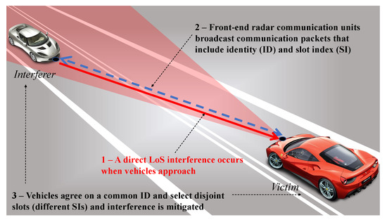
Figure 3.
RadChat protocol explanation.
Vehicles are assumed to be synchronized within an error of in order to agree on the joint time notion, where synchronization is provided by GPS clocks. The maximum number of time-frequency resources or SIs is denoted by and is calculated based on how many non-conflicting radars can be placed within a chirp and within each time slot in a radar frame. is given by
where is the allowed margin for synchronization error within a chirp time (refer to [1] for a detailed explanation of RadChat).
3.2. Synchronization-Free RadChat
Sync-free RadChat removes the dependency on a GPS clock for synchronization, and is based on broadcasting relative times until a radar starts, rather than the absolute times. Taking propagation delays into account, broadcasting of the relative time instead of the absolute time of the start of radar sensing results in different time-frequency resource allocations experienced for RCUs located at different distances, as depicted in Figure 4. The RCUs and on two separate vehicles, which are within the FoV of each other, broadcast the green and purple communication packets, respectively, prior to radar sensing. These communication broadcast packets include the time left until the radar transmission for the RCU and for the RCU . The propagation delay causes each RCU to observe a different time-frequency resource for radar signals when the relative times are broadcast. The timeslot , during which the radar sensing takes place, does not cover exactly the same time duration for the RCUs and .
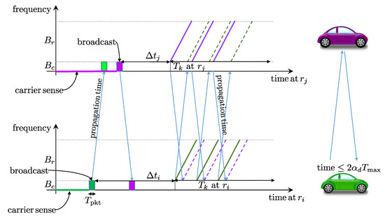
Figure 4.
Time-frequency resource allocation for RCUs located at different distances. The radar and communication signals occupy the 3D space (distance-time-frequency) as shown. The RCUs and broadcast the green and purple communication packets, respectively, which include the time left until the radar transmission and . Note that the propagation delay causes each RCU to observe a different time-frequency resource when the relative times are broadcast.
By Sync-free RadChat, we have an unsychronized slotting of time among different vehicles. However, since all RCUs within a vehicle are assumed to be connected to a central controller, we assume the slot timing to be the same for all RCUs mounted on the same vehicle.
Note that the vulnerable period of radar chirps might overlap and mutual radar interference might appear in Figure 4 if propagation delays become larger. Moreover, unsynchronized timing among vehicles might result with radar interferences for radars employing different SIs if the propagation delay gets large compared to the vulnerable period V computed in Equation (1). Hence, V needs to be reshaped to avoid such cases.
3.2.1. Design Parameters
In order to account for all possible propagation delays, the propagation delay of the furthest away possible interferer must be taken into account in the design of Sync-free RadChat protocol. The propagation delay of the furthest away communicated possible interferer is , which makes the round-trip delay to such a distant interferer . Two vehicles might communicate, select different SIs, and might have a maximum of round-trip propagation delays among each other, as shown in Figure 4. For Sync-free RadChat, with unsynchronized timing, the vulnerable period should be designed so as to be greater than this maximum propagation delay among vehicles. This way, it is guaranteed that the radar chirps of these two vehicles are separated far enough in time so that the radar signals do not interfere. In order for a furthest away possible interferer (green vehicle) not to select a different SI (than the purple vehicle), the vulnerable period for Sync-free RadChat, denoted by , should satisfy
This way, Sync-free RadChat forces an RCU to select a different SI with a radar starting time shifted by more than compared to the received radar staring time, which results in radar chirps of different RCUs to be separated by at least the maximum round-trip propagation time. For , that is, dense VANETs with signal blockage hindering interference coming from further than the round-trip-radar distance or communication signal ranges less than a radar round-trip range, the vulnerable period of RadChat V based on absolute times always satisfies this condition [1]. Hence, for dense VANETs, we have shorter vulnerable periods, and possibly many potential interferers. However, in sparse VANETS or with communication signal ranges more than the radar round-trip range (where ), the Sync-free RadChat requires longer vulnerable periods () than the absolute-time RadChat ().
Note that for Sync-free RadChat, there might still be a clock drift for each RCU from the instant that the communication packet is broadcast until the time radar chirps start, which is a maximum time slot duration . For typical FMCW automotive radars, assuming a ms, , and a clock stability of 10 ppm, this results in a 0.1 s clock shift at most, which is negligible.
3.2.2. Scheduling
Sync-free RadChat uses a simple medium access control mechanism: CSMA/CA with no retransmissions. If the channel is sensed to be idle, the communication packet is broadcasted; otherwise, the packet is killed and a new packet is generated to be transmitted in the next radar frame after . With Sync-free RadChat, an RCU with a radar chirp sequence during time slot , the carrier senses the channel at a random time uniformly distributed over the interval , where is the duration of the packet. If the channel is sensed idle during a SlotTime , the communication packet is broadcast. If the channel is busy, the packet is dropped and the same procedure is repeated in the coming radar frames.
RadChat sends retransmissions, whereas Sync-free RadChat does not. A retransmission mechanism is not feasible for Sync-free RadChat because the content of the broadcast communication packet includes a relative time , which is difficult to quickly modify immediately at the physical layer in case of a busy channel. There is a trade-off in using retransmissions. Retransmissions may increase the possibility of successful reception, but it may also make the channel busy, hindering other RCUs. The performance analysis conducted in Section 4 shows that the lack of retransmissions does not impact the performance of Sync-free RadChat.
3.2.3. Maximum Available Resources
The maximum number of RCUs with Sync-free RadChat is denoted by and is given by
which is independent of synchronization errors among vehicles different than RadChat.
Radar chirps of different RCUs within a time slot might be separated more due to the increased vulnerable period for Sync-free RadChat, but less due to no need for a synchronization error margin within a chirp .
4. Performance Evaluation and Results
Sync-free RadChat does not need GPS-clock-based synchronization for mitigating interference. In this section, we compare its radar interference mitigation performance with RadChat in terms of the fraction of blinds, blind duration, protocol convergence time, and maximum number of RCUs.
4.1. Scenario and Parameters
The interference mitigation capability of Sync-free RadChat protocol is investigated for two different high-way traffic scenarios given in Figure 5 [17]: (1) a fleet of vehicles in one lane with vehicles moving in the same direction (Scenario-I), and (2) two single-lane vehicles moving towards each other (Scenario-II).

Figure 5.
Traffic scenarios: (a) Scenario-I: One fleet moving in the one direction, and (b) Scenario-II: two fleets approaching each other. Vehicles are represented by rectangles, whereas waypoints, that is, the starting and ending of paths for each vehicle are indicated by dots with the same color.
A total of vehicles with one front-end and one back-end RCU move with the same speed and are equally spaced with 20 m. This leads to a dynamically changing topology for Scenario-II. The LoS and ground-reflected paths end up with a limited number of connections among vehicles for the multi-hop VANETs for both scenarios, where each vehicle can communicate and generally radar-sense two vehicles at the back and two vehicles at the front, due to a reflected wave underneath the vehicles (more vehicles are connected when two fleets approach in Scenario-II). Since we ignore reflections from other vehicles and since each vehicle is assumed to be equipped with one front-end and one back-end RCU with long-range radar sensing functionality, we do not have any radar interference among radars within a single vehicle.
The value of is assigned so that the maximum range of a direct interferer taken into account is set as 1 km, equal to the communication range. A total of 25 Monte Carlo simulations of 2 s duration were performed, with the parameters summarized in Table 2. A total simulation duration of 2 s might cover an interval where no GPS signals are received at all inside a tunnel or under a canyon effect. This does not impact the simulation results of Sync-free RadChat, since it functions independently of GPS. However, a signal outage of 2 s would require a setting of 2 s, which would result in RadChat performance similar to the state-of-the-art radars. Briefly, it is not the simulation duration, but the signal outage duration that matters.
Table 2.
Simulation parameters [1].
4.2. Maximum Available Resources versus Synchronization Error
The maximum number of RCUs, which can be coordinated so as not to interfere, with RadChat () and Sync-free RadChat () are compared. Figure 6 shows the calculated and values versus synchronization error for various values. There is a compromise between and with RadChat, as shown in Equation (3), whereas is independent of synchronization errors among vehicles for Sync-free RadChat. Increasing and increases the vulnerable period for RadChat, leading to a decreased number of radars that can be scheduled not to interfere. Since Sync-free RadChat is independent of synchronization errors, we observe that it can schedule more non-interfering radars compared to RadChat for small and larger synchronization errors.
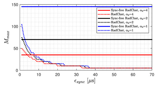
Figure 6.
Trade-off between the allowed synchronization error and the maximum number of RCUS for RadChat interference mitigation.
4.3. Convergence Latency and Blind Duration
The average convergence latency for interference mitigation for RadChat and Sync-free RadChat are compared in Figure 7a for both traffic scenarios. is the protocol convergence time, and convergence occurs after all of the RCUs in the VANET are assigned the same ID and different SIs, starting with totally random radars. Likewise, the average blind durations experienced versus the number of total vehicles in the VANET () are compared in Figure 7b.
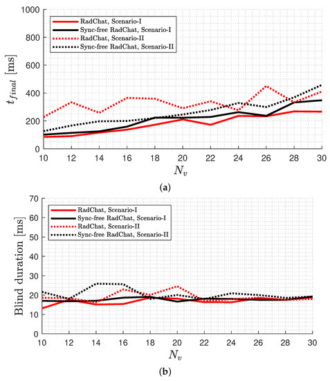
Figure 7.
Comparison of the following values for a varying number of vehicles for RadChat and Sync-free RadChat for both scenarios ( 2.5378): (a) average convergence latency and (b) average blind duration.
It is observed that as the number of vehicles increases, the convergence latency tends to increase, since it takes more time to propagate the scheduling information over a larger VANET. The convergence latency is more for Scenario-II where two disjoint VANETs combine, since decisions for radar scheduling are done disjointly in the beginning and an agreement is reached after the two fleets approach. The convergence latency of Sync-free RadChat is slightly better than RadChat for Scenario-II, whereas RadChat performs slightly better for Scenario-I. Both protocols resolve radar interference in about 100 ms for 10 vehicles and about 400 ms for 30 vehicles.
The average blind duration is observed to be almost the same for a various number of vehicles being slightly larger for Scenario-II, which is due to the limited number of connections among RCUs.
We also investigated the performance for varying , which results in a significant difference in the supported number of RCUs . Although not given in this article due to space limitation, the convergence latency and the blind duration can be concluded to be independent from for the considered multi-hop VANETs, due to the limited number of mmWave connections which do not change with an increasing maximum range of communicated interferers.
4.4. Fraction of Blinds
The fraction of blinds, defined as the ratio of the number of interfering RCUs and the total number of RCUs, is shown in Figure 8 for Scenarios I and II, respectively. Without coordination of radars, around 5–7% of automotive radars are blinded by interference, and this ratio remains the same for Scenario 1 and increases up to as the two fleets approach each other in Scenario-II. With Sync-free RadChat, all RCUs are assigned disjoint slots within about ms for and ms for for both scenarios. The fraction of blinds becomes nonzero for Scenario-II after convergence, and interference pops up as the connectivity graph changes, which is mitigated within about 20 ms. We observed that there is no difference between RadChat and Sync-free RadChat protocols in terms of the interference mitigation performance throughout the simulation duration.
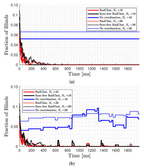
Figure 8.
The average fraction of blinds with and without RadChat compared with Sync-free RadChat (averaged over 25 realizations) and for and for (a) Scenario-I and for (b) Scenario-II.
Finally, we compare the performance of interference mitigation of Sync-free RadChat with RadChat under different synchronization errors in the VANET in Figure 9 for 10 and Scenario-II. Each vehicle’s GPS clock is assumed to have a uniformly distributed synchronization error within . Here, , which results in 11 concurrent radar transmissions per time slot. Hence, RadChat can handle at most a μs synchronization offset among vehicles, and is observed to fail in deleting radar interference for larger values, whereas Sync-free RadChat operates perfectly well.
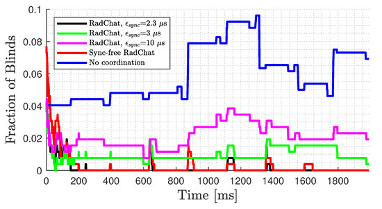
Figure 9.
Fraction of blinds for various synchronization errors.
5. Conclusions
We proposed a synchronization-free protocol (Sync-free RadChat) for distributed radar interference mitigation based on radar communications. It relies on broadcasting relative radar starting times and CSMA/CA with no retransmissions. We have shown that Sync-free RadChat functions well in terms of the convergence latency, blind durations and fraction of blinds, simulated under realistic automotive radar and vehicular communication parameters.
Sync-free RadChat eliminates the dependency on GPS clocks, and hence provides a basis for a safe automotive radar mutual interference mitigation even in tunnels or urban canyons, or under a GPS spoofing attack, when vehicles become unsynchronized due to unequal clock drifts.
Sync-free RadChat constitutes an example of a cooperative radar communications-based interference-free radar sensing mitigation protocol, which does not require synchronization among vehicles. However, we expect the interference-mitigation capability of the Sync-free RadChat to degrade when not all vehicles are deployed with it. Previously, we showed that RadChat protocol was able to mitigate all interference with 100% deployment, whereas about 40% of the interference is mitigated with 50% deployment [1]. Sync-free RadChat is expected to have a similar performance. Hence, Sync-free RadChat can mitigate all the radar interference and achieve driving safety if it is deployed by all radars or radar communication units, which requires standardization among all automotive manufacturers and future radar communication unit suppliers.
Author Contributions
C.A. and H.W. proposed the problem formulation. O.E., H.H. and M.R. provided feedback on reasonable parameters and scenarios. C.A. developed, implemented and simulationed the method. All authors proof-read the article. All authors have read and agreed to the published version of the manuscript.
Funding
This research was supported by Vinnova grant 2018-01929 and the Chalmers Transport Area of Advance project IRIS.
Institutional Review Board Statement
Not applicable.
Informed Consent Statement
Not applicable.
Data Availability Statement
Not applicable.
Conflicts of Interest
There are no conflict of interest to report.
References
- Aydogdu, C.; Keskin, M.F.; Garcia, N.; Wymeersch, H.; Bliss, D.W. RadChat: Spectrum sharing for automotive radar interference mitigation. IEEE Trans. Intell. Transp. Syst. 2019, 22, 416–429. [Google Scholar] [CrossRef]
- Petrov, V.; Fodor, G.; Kokkoniemi, J.; Moltchanov, D.; Lehtomaki, J.; Andreev, S.; Koucheryavy, Y.; Juntti, M.; Valkama, M. On unified vehicular communications and radar sensing in millimeter-wave and low terahertz bands. IEEE Wirel. Commun. 2019, 26, 146–153. [Google Scholar] [CrossRef]
- Hasan, K.F.; Feng, Y.; Tian, Y. GNSS time synchronization in vehicular ad hoc networks: Benefits and feasibility. IEEE Trans. Intell. Transp. Syst. 2018, 19, 3915–3924. [Google Scholar] [CrossRef]
- GPS Clock Synchronization. Available online: https://www.orolia.com/resources/knowledge-center/gps-clock-synchronization (accessed on 30 September 2020).
- Hussein, S.; Krings, A.; Azadmanesh, A. VANET clock synchronization for resilient DSRC safety applications. In Proceedings of the 2017 Resilience Week (RWS), Wilmington, DE, USA, 18–22 September 2017; pp. 57–63. [Google Scholar]
- Li, Z.; Ding, Z.; Wang, Y.; Fu, Y. Time synchronization method among VANET devices. In Proceedings of the 2017 International Conference on Wireless Communications, Signal Processing and Networking (WiSPNET), Chennai, India, 22–24 March 2017; pp. 2096–2101. [Google Scholar]
- Liang, J.; Wu, K. An extremely accurate time synchronization mechanism in fog-based vehicular ad hoc network. IEEE Access 2020, 8, 253–268. [Google Scholar] [CrossRef]
- Ansere, J.A.; Han, G.; Wang, H. A novel reliable adaptive beacon time synchronization algorithm for large-scale vehicular ad hoc networks. IEEE Trans. Veh. Technol. 2019, 68, 565–576. [Google Scholar] [CrossRef]
- Haider, S.; Abbas, G.; Abbas, Z.H. VLCS: A novel clock synchronization technique for TDMA-based MAC protocols in VANETs. In Proceedings of the 4th International Conference on Emerging Trends in Engineering, Sciences and Technology (ICEEST), Karachi, Pakistan, 10–11 December 2019; pp. 1–6. [Google Scholar]
- Nasrallah, Y.Y.; Al-Anbagi, I.; Mouftah, H.T. Distributed time synchronization mechanism for large-scale vehicular networks. In Proceedings of the 2016 International Conference on Selected Topics in Mobile Wireless Networking (MoWNeT), Cairo, Egypt, 11–13 April 2016; pp. 1–6. [Google Scholar]
- Buller, W.; Wilson, B.; Garbarino, J.; Kelly, J.; Subotic, N.; Thelenand, B.; Belzowski, B. Radar Congestion Study; NHTSAreport (Report No. DOT HS 812 632); National Highway Traffic Safety Administration: Washington, DC, USA, 2018. [Google Scholar]
- Aydogdu, C.; Keskin, M.F.; Carvajal, G.K.; Eriksson, O.; Hellsten, H.; Herbertsson, H.; Nilsson, E.; Rydstrom, M.; Vanas, K.; Wymeersch, H. Radar Interference Mitigation for Automated Driving: Exploring Proactive Strategies. IEEE Signal Process. Mag. 2020, 37, 72–84. [Google Scholar] [CrossRef]
- Viriyasitavat, W.; Boban, M.; Tsai, H.; Vasilakos, A. Vehicular communications: Survey and challenges of channel and propagation models. IEEE Veh. Technol. Mag. 2015, 10, 55–66. [Google Scholar] [CrossRef]
- Liang, L.; Peng, H.; Li, G.Y.; Shen, X. Vehicular communications: A physical layer perspective. IEEE Trans. Veh. Technol. 2017, 66, 10647–10659. [Google Scholar] [CrossRef]
- Sarabandi, K.; Li, E.S.; Nashashibi, A. Modeling and measurements of scattering from road surfaces at millimeter-wave frequencies. IEEE Trans. Antennas Propag. 1997, 45, 1679–1688. [Google Scholar] [CrossRef]
- Al-Hourani, A.; Evans, R.J.; Kandeepan, S.; Moran, B.; Eltom, H. Stochastic geometry methods for modeling automotive radar interference. IEEE Trans. Intell. Transp. Syst. 2017, 19, 333–344. [Google Scholar] [CrossRef]
- Aydogdu, C.; Keskin, M.F.; Wymeersch, H. Automotive radar interference mitigation via multi-hop cooperative radar communications. In Proceedings of the EuMA European Microwave Association, 17th European Radar Conference EuRad 2020, Utrecht, The Netherlands, 10–15 January 2021. [Google Scholar]
- Aydogdu, C.; Garcia, N.; Wymeersch, H. Improved Pedestrian Detection under Mutual Interference by FMCW Radar Communications. In Proceedings of the IEEE International Symposium on Personal, Indoor and Mobile Radio Communications (PIMRC), Workshop on 5G V2X Communications for Connected Autonomous Driving, Bologna, Italy, 9–12 September 2018. [Google Scholar]


Publisher’s Note: MDPI stays neutral with regard to jurisdictional claims in published maps and institutional affiliations. |
© 2021 by the authors. Licensee MDPI, Basel, Switzerland. This article is an open access article distributed under the terms and conditions of the Creative Commons Attribution (CC BY) license (https://creativecommons.org/licenses/by/4.0/).