Article

Effectiveness of the Novel Rehabilitation Method of Seismically Damaged RC Joints Using C-FRP Ropes and Comparison with Widely Applied Method Using C-FRP Sheets—Experimental Investigation

by
Emmanouil Golias
1,
Adamantis G. Zapris
1,
Violetta K. Kytinou
1,
George I. Kalogeropoulos
2,
Constantin E. Chalioris
1,* and
Chris G. Karayannis
1
1
Laboratory of Reinforced Concrete and Seismic Design of Structures, Civil Engineering Department, School of Engineering, Democritus University of Thrace, 67100 Xanthi, Greece
2
Laboratory of Reinforced Concrete and Masonry Structures, Civil Engineering Department, School of Engineering, Aristotle University of Thessaloniki, 54124 Thessaloniki, Greece
*
Author to whom correspondence should be addressed.
Sustainability 2021, 13(11), 6454; https://doi.org/10.3390/su13116454
Submission received: 10 May 2021 / Revised: 30 May 2021 / Accepted: 2 June 2021 / Published: 6 June 2021
(This article belongs to the Special Issue Innovations in Sustainable Materials and Construction Technologies)

Abstract

:
The necessity of ensuring the long-term sustainability of existing structures is rising. An important issue concerning existing reinforced concrete (RC) structures in seismically active regions is that a significant number of them lack the required earthquake-resistant capacities to meet the increased design earthquake demands. Inexpensive, fast and long-term strengthening strategies for repairing/strengthening RC structures are urgently required, not only after destructive earthquakes, but even before they occur. Retrofitting existing buildings extending their service life rather than demolishing and rebuilding new ones is the best option in terms of economic gain and environmental protection. This paper experimentally investigates the effectiveness of externally applied (i) carbon fiber-reinforced polymer (C-FRP) ropes in X-type form and (b) C-FRP sheets that are bonded on both sides of the joint area of RC beam-column joint connections. Six comparative full-scale exterior RC beam-column joint specimens were tested under reverse cyclic deformation. Two of them were control specimens, two were strengthened using C-FRP ropes (novel technique) and two were retrofitted using C-FRP sheets (widely used technique). Extensive comparisons and discussion of the test results derive new quantitative and qualitative results concerning the seismic capacity and the service life extension of the strengthened RC members using the proposed retrofitting scheme.

1. Introduction

Rehabilitation methods of existing infrastructures have an important role in ensuring sustainable development. The term sustainability refers to structures’ ability to retain their performance at a reasonable cost and with minimal environmental impact [1]. The majority of existing structures are composed of reinforced concrete (RC), which, despite the significant environmental impact of the RC industry, is the most widely used building material worldwide [2]. The main issue concerning existing structures is that a significant number of them lack the required earthquake-resistant capacities to meet the increased design earthquake demands [3].
Considering the abovementioned, it is clear that inexpensive, fast and long-term strengthening strategies for repairing/upgrading RC structures are urgently required, not only after destructive earthquakes, but even before they occur [4]. Retrofitting existing buildings rather than demolishing and rebuilding new ones is the best option in terms of economic gain and environmental protection [5,6]. Therefore, the investigation of strengthening and rehabilitation techniques for RC structural members that have suffered damage during an earthquake and are to be reused afterwards is a very important area of research, since both the safety of the structures and economic interests are involved [7,8].
Studies on structural damages caused by earthquakes worldwide have shown that the joint areas of RC frame-system structures are the most vulnerable [9]. A large number of the existing RC buildings have been constructed according to older regulations without particular planning for the reinforcement of the joints [10,11,12]. The inadequate shear reinforcement in the joint area and especially in external joints has been proven to lead to brittle response and is the primary cause of the collapse mechanism formation during earthquake loading [13]. The response of beam-column joints is affected by a variety of parameters such as bond, shear load, confinement and fatigue, which are not yet well understood even independently, and they progressively reduce the joint’s stiffness and strength. Therefore, the successful repair or strengthening of joints that have previously been damaged during cyclic loading caused by earthquakes is essential in order to enable the use of the affected structure again [14,15,16]. Detailed design recommendations have been introduced on the basis of the research and development of repair techniques in Europe and the United States in past decades [17,18,19,20,21]. Regardless, the further development of cost-effective rehabilitating strategies for RC frame joints remains of great interest.
A well-known repair technique commonly used after earthquake excitations is based on the infusion of thin resin under pressure in the cracking system of the damaged body. The effectiveness of this technique, which has been widely used, has been experimentally confirmed by Karayannis et al. [22,23]. In addition, the injection of resin into the crack system in combination with external fiber-reinforced polymer (FRP) sheet adhesion has been proven to be particularly effective in restoring and improving joint response [24,25]. A recent study has also verified that a widely applied in practice technique, which combines the use of high-strength repair mortar along with external application of carbon FRP sheets, can treat damage in the joint area caused by earthquakes more rapidly and effectively without the use of costly injection measures [26]. The effectiveness of high-strength mortars as repair materials has also been individually confirmed [27,28]. In either case, the use of FRP sheets for joint rehabilitation has gained popularity as a viable and cost-effective alternative to conventional systems, such as RC jacketing. Most importantly, in terms of sustainability, FRP manufacturing has a significantly lower environmental effect than traditional material production methods. The manufacturing of FRP materials releases fewer carbon emissions and consumes less energy than steel and concrete [29].
The repair and strengthening of joints with external bonded FRP sheets exhibit significant advantages, such as an easy and fast application [30,31,32]. Moreover, the initial dimensions of the joints remain unchanged and consequently the dynamic characteristics of the structure are mainly unaffected. The application and investigation of FRP rehabilitation/strengthening solutions for joint areas of existing RC structures has been the subject of a variety of experimental and analytical studies [33,34,35,36]. The effectiveness of FRP composites in enhancing the seismic strength of deficient RC joints has been demonstrated in numerous experimental studies [24,25,37,38,39,40,41,42,43,44]. The ability to increase the shear resistance, stiffness and ductility was investigated through experimental studies using externally bonded FRP applications. There are studies focusing on beam-column joints shear strengthening, proving the efficiency of the suggested FRP strengthening configurations in avoiding the shear failure of the joint and enabling a less brittle behavior [45,46,47]. To achieve shear strengthening, various types of FRP exterior application shapes have been investigated, such as U-shaped [48,49,50,51,52,53], X-shaped [54,55,56] and T-shaped [57]. In addition to local strengthening of the joint area, others have attempted to improve the performance of the surrounding components, such as bond enhancement of the beam’s bottom reinforcement bars [58,59,60], improvement of the columns’ flexural performance and column confinement [16,60,61,62,63,64]. The most common mode of failure in FRP-strengthened specimens that were tested was the debonding of FRP composites from the concrete surface. A mechanical anchorage at the free ends of FRP sheets has been developed to address this shortcoming [48,57,65,66,67]. Although the FRP anchorage systems applied in several studies have proven successful in increasing the efficiency of joint rehabilitation using FRP sheets, the complex construction procedures impose difficulties in practical uses.
In general, studies have demonstrated the success of FRP strengthening. The performed tests have mainly concentrated on FRP configurations applied to the entire joint subassembly, which includes the joint area and as well the surrounding RC members. However, in real RC buildings, the presence of transverse beams is crucial for the application [68]. Due to this basic restriction in the application of FRP sheets, it is desirable to find an innovative technique that gathers the advantages mentioned above without the construction restrictions. The aforementioned remarks have posed new challenges in the growth of novel strengthening methods that can be implemented with minimal disruption of the structure. A recent method introduced by the authors [69] involves replacing the FRP sheets with a bundle of unidirectional fibers (FRP rope), inserted either as near surface mounting (NSM) or as embedded through section (ETS) in joints, and it seems to be a promising technique. FRP ropes have been used in previous research as the main reinforcement for strengthening flexure deficient beams in the support area [21,70] as well for the shear strengthening of deep beams [71].
This paper discusses two sets of experiments that were carried out on full-scale RC beam-column joints. The specimens were subjected to cyclic loading and two different FRP rehabilitation methods were applied. Some specimens where rehabilitated using the technique widely applied in practice that combines high strength mortar with external application of carbon FRP (C-FRP) sheets, while others were strengthened using the recently proposed technique with C-FRP ropes. Some of the experimental specimens have previously been presented by the authors in recently published studies [26,69]; however, the scope of the current study is to examine the effectiveness of the novel C-FRP rope strengthening method compared to the frequently used C-FRP sheet application. New experimental results of the application of the novel method are also presented to support the effectiveness investigation. Furthermore, a thorough description of the promising novel technique’s application on external RC beam-column joints is also provided.

2. Experimental Program
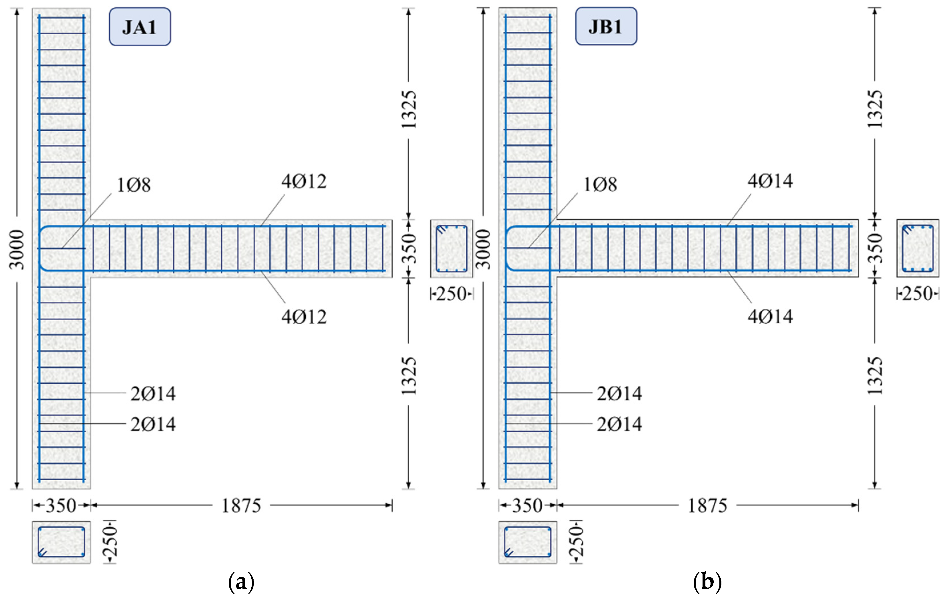
2.1. Test Specimens

The efficacy of RC frame joints under seismic actions is experimentally investigated using real-scale test specimens and their response is represented in terms of load-bearing capacity and deformation hysteretic curves. The investigation program consists of six exterior beam-column RC joint subassemblages tested under cyclic loading. The specimens are sorted into two series: Series A, in which the damage is expected to develop in the beam, and Series B, in which the joint will be mainly damaged. Each series consists of three specimens, of which the first is a control specimen, the second is repaired and strengthened with externally applied C-FRP sheets specimen and the third is a specimen that contains externally applied C-FRP ropes. Thus, Series A consisted of the specimens JA1, JA1E and JA1FXb, where JA1 is the control specimen, JA1E was repaired and enhanced with C-FRP sheets and JA1FXb was strengthened with C-FRP ropes. Series B consists of the specimens, JB1, JB1FX and JB1E, where JB1 is the control specimen and JB1E and JB1FX were repaired and enhanced with C-FRP sheets and C-FRP ropes, respectively.
The geometry and cross-section dimensions are the same for all test specimens and were chosen on the basis of common cast-in-place RC frame structures (floor height of 2.95 m, beam length = 0.5 × span width of 4.0 m). The total length of the column is 3.00 m and that of the beam is 1.875 m with cross-section dimensions 350/250 mm (Figure 1).
The longitudinal reinforcement of the JA1 specimen’s column consists of 1Ø14 in each corner. Stirrups Ø8/10 cm are installed as a shear reinforcement of the column, and a single additional stirrup is arranged in the joint area. The beam is reinforced with 4Ø12 in the top and bottom layer and with Ø8/10 cm stirrups. The beam reinforcement for the test specimen JB1 is the same as for JA1, with the difference being that the top and bottom layers of the beam are each reinforced with 4Ø14 (Figure 1). In specimens JA1E and JB1E, C-FRP sheets have also been externally applied in accordance with the layout of Figure 2. C-FRP ropes of 6 mm diameter have been applied externally in an X-shape at each side of JB1FX specimen’s joint area (Figure 3b). While on specimen JA1FXb, besides the X-shaped rope application in the joint area, C-FRP ropes have also been applied at each side on the top and bottom of the surrounding beam (Figure 3a).

2.2. Materials

In order to determine the compressive strength of the concrete used, supplementary compression tests of six 150 × 300 mm cylinders were also carried out. The mean value of the compressive strength of concrete was fcm = 34 MPa. The steel reinforcement for both longitudinal and transverse reinforcement was B500C with a mean steel yield strength equal to fy = 550 MPa. The C-FRP rope (SikaWrap® FX-50 C, Sika Hellas ABEE, Krionerion, Greece) that has been used for the above-mentioned specimens was a bundle of unidirectional carbon fibers with tensile strength equal to 4000 MPa, modulus of elasticity equal to 240 GPa and cross-section area >28 mm2, according to manufacturer’s data. Two types of epoxy resins were used: resin type A (Sikadur®-52) for the impregnation of dry fibers and type B (Sika AnchorFix®-3+) for the anchorage of system. For the strengthening of specimens with external C-FRP sheets with thickness of tf = 0.168 mm, tensile strength equal to 4300 MPa, modulus of elasticity equal to 240 GPa and elongation at rupture 1.7% were used.

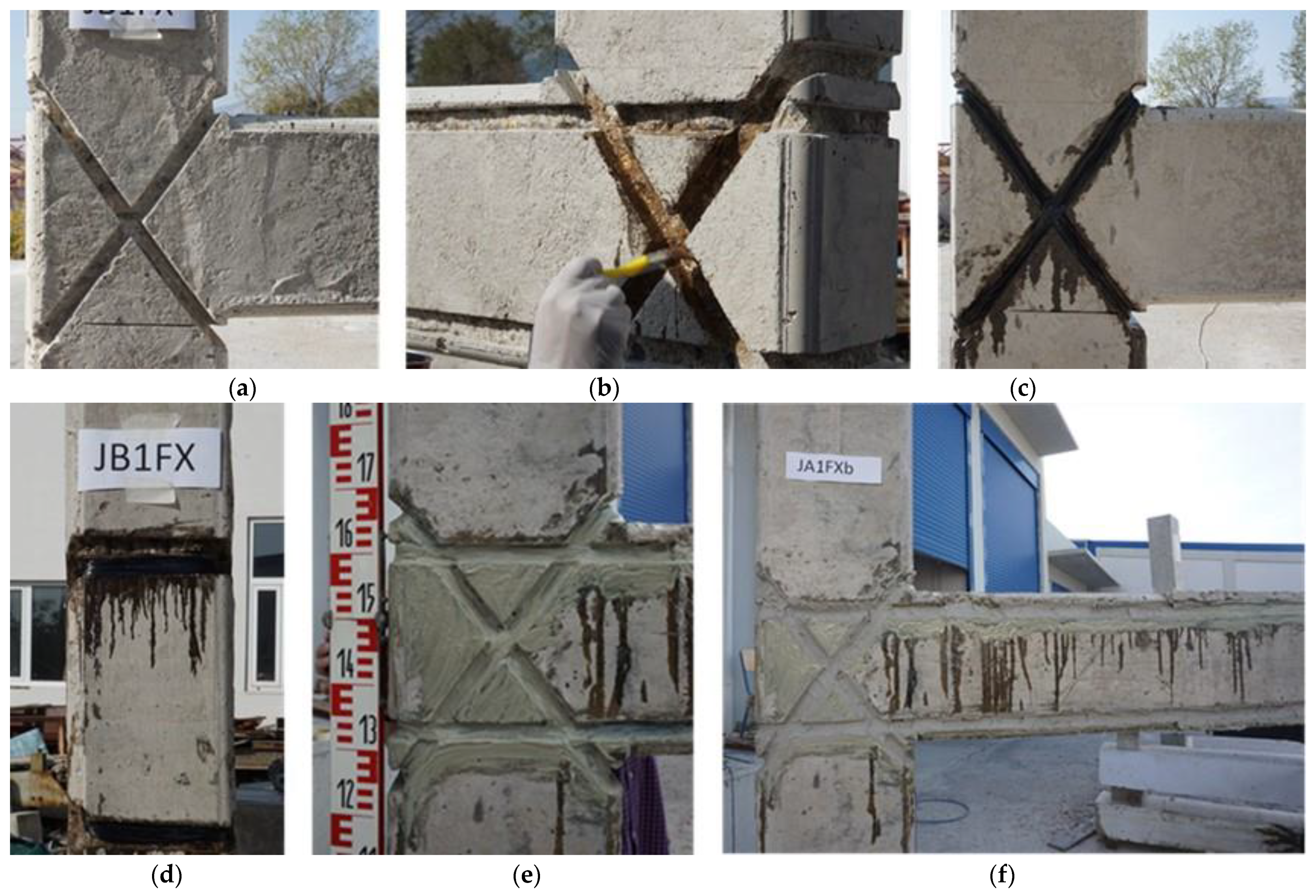
2.3. Specimen Repair and Strengthening Procedure

The strengthening procedure of specimens, as it took place at the Laboratory of Reinforced Concrete and Seismic Design of Structures of the Democritus University of Thrace, is described, step-by-step, as follows. In the first step, control specimens JA1 and JB1 were subjected to a cyclic load exceeding the elastic load-bearing capacity in order to simulate the earthquake effect. The specimens showed signs of damage after being experimentally tested and were therefore rehabilitated. To proceed with the rehabilitation, the loose concrete pieces were removed at first. The affected area was then shuttered and grouted with the grouting mortar. After a 7-day curing period, the strengthening process began in order to produce the new test bodies JA1E and JB1E from the test bodies JA1 and JB1 by jacketing the joint region (Figure 4a). First, a diamond cup disk was used to clean the substrate. A suction aid was then used to clear the dust. The adhesive was applied evenly to the prepared surface with the roller. The C-FRP sheets were then placed using a rubber spatula and a pressure roller and were pressed only in the longitudinal direction of the fibers. The arrangement of the C-FRP sheets is shown in Figure 2. The surface was then primed with epoxy resin adhesive and treated again in the direction of the fibers with a pressure roller and rubber spatula until all fibers were fully wetted and there were no air pockets (Figure 4b,c).
The other test specimens JA1FXb and JB1FX are produced by strengthening the control specimens JA1 and JB1 by using C-FRP fiber ropes (see Figure 3). At first, the direction of the carbon fiber ropes was drawn on the surface of specimens. With the use of a grinder, the incision of U-shaped notches was formed according to the dimensions and specifications of the material’s supplier in order to achieve the encapsulation of C-FRP ropes (Figure 5a). The dimensions of the notches in the beams were 25 mm in depth and 30 mm in width. To avoid the accumulation of stress and local rope rupture, special attention was paid to create a proper curvature at the rope’s bending points. During the incision-making process, special care was given in order to protect the steel bars from being damaged. In order to achieve adequate and efficient anchorage of the free ends of the C-FRP rope, a vertical opening was drilled in a 90° axis relation to the web of the beam. The opening was drilled at the end of the beam with a diameter of 16 mm and length of 80 mm. The notches were cleaned thoroughly from dust and concrete residues (and generally of materials of lower adhesion) using compressed air from a special pistol. Epoxy resin type A (Sikadur®-52) was applied in the notches using a small painting brush (Figure 5b). The C-FRP rope was cut in the required dimensions with scissors after thorough saturation of the C-FRP ropes in epoxy resin according to EN 1504-4. The C-FRP ropes were placed into notches and holes under pressure with care in order to remove air and excessive amount of resin (Figure 5c,d). While the rope was impregnated with resin and was in the effective time of the resin, the voids in the notches were filled with epoxy resin type B (Sika AnchorFix®-3+) in order to achieve a high level of adhesion between concrete and the fibers of C-FRP rope (Figure 5e,f).

2.4. Test Setup and Instrumentation

Test set-up and instrumentation details are shown in Figure 6. The test specimen was installed after being rotated 90 degrees with the beam pointing upwards vertically and the column horizontally. Supports that allow rotation were used to simulate the inflection points, which are assumed to occur at a point in the middle of the column’s deformable height in a laterally loaded RC frame structure. A compressive axial load with a constant value equal to Nc = 0.05 Ac fcm was applied to the column during the tests. In practice, such frame structures are loaded with a relative axial normal force equal to νc = Nc/(Ac fcm) ≥ 0.05, so experiments are typically based on a conservative lower value of νc = 0.05 to 0.10. A value lower than 0.05 axial normal force would indicate unrealistic joint stress. All specimens were subjected to full cycle reverse deformations that were imposed near the free end of the beam by a swivel connector with the actuator. The moment arm for the applied load was equal to 1.475 m.
The imposed load was measured by a load cell with accuracy equal to 0.025 kN, the displacements of the column were measured by a linear variable differential transducer (LVDT) with accuracy equal to 0.01 mm and the displacements of the beam and the joint area were measured by radial a variable differential transducer (RVDT) with accuracy equal to 0.01 mm (Figure 6).

2.5. Loading History

The test specimen was subjected to displacement-controlled cyclic loading. The test cylinder used to apply the deformation engages the beam’s free vertical end (Figure 7). The moment at the joint is produced by a 1.475 m long lever arm. The test specimen was loaded in seven stages with progressively increasing applied deformation of 8.5 mm, 12.75 mm, 17 mm, 25.5 mm, 34 mm, 51 mm and 68 mm. The deformation was applied three times at each load level, in both positive and negative directions.
When testing RC structural members, it is critical to choose the load intensity and load rate so that both the specimen load-bearing limit/capacity requirements and the results are consistent with those expected in real-world buildings subjected to seismic actions. In the case of simulated seismic loads that cause non-elastic deformations, the load-bearing capacity, specimen resistance and loading action cannot be viewed separately from one another. The basic parameters for determining the capacity curve of an element are material strength, stiffness, inelastic deformation ability (ductility) and cumulative damage capacity variables, such as energy dissipation. These parameters are expected to deteriorate as the number of damage cycles and the amplitudes in the experiment increase. Any load acting on the element that exceeds its elastic load-bearing capacity results in permanent damage (possibly plastic deformations). The implemented loading scheme purposely focuses on load levels, with each level having many load changes within a load level, since repeated load cycles cause damage, which is more common with moderate earthquake loads.
In this study, the load level was chosen so that the structural member response is safe for most applications. This is accomplished in this case by a loading sequence with multiple cycles. The selected test program and the loading sequence were deliberately chosen so that individual structural performance parameters, such as envelope curves of the hysteretic responses, dissipated energy, stiffness and viscous damping, can be determined and used for damage assessment in any earthquake event.

2.6. Design of the Specimens

Internal mechanics and seismic reactions of beam-column connections in RC frame structures have not yet been extensively researched and understood. There is currently no widely accepted method to design RC frame joints subjected to cyclic loading, normal and shear forces and bending. In any case, a sufficient estimation of the horizontal shear force (Vjh) is an important factor for evaluating the shear stress τ and thus for calculating the required shear reinforcement. The horizontal shear force of the joint can be calculated as Vjh = As1fsuVcol, where As1 is the tensile reinforcement of the beam, fsu is the steel strength and Vcol is the column shear force, which can be calculated as Vcol = Mb,y/ℓc. Mb,y is the yield moment of the beam and c = (c,up + c,lo)/2 is the average length of the joint’s upper and lower supports. According to Eurocode 8 EN 1998-1 (2004) [72], the maximum horizontal shear force for the test specimen JA1 that can be carried into the joint by the beam’s tensile reinforcement is Vjhd = 0.23 MN, and the corresponding shear stress is τ = 2.70 MPa. For the test specimen JB1, is Vjhd = 0.32 MN and τ = 3.67 MPa, respectively. It should be noted that, due to transverse tensile loads, the compression strut used in the joint in compliance with Eurocode 8 must not exceed the concrete strength. This requirement is met by Equation (1):
V j h d     0.8 · η · f c d 1     ν d η · b j · h j c
Applying this equation to the specimen joints, the requirement is met if Vjhd ≤ 0.50 MN, which means it is met for all test specimens. According to ACI, the ratios ΣMRc/MRb > 1.40 and φVnVu must also be satisfied for joints [73]. For the test specimen JA1, ΣMRc/MRb = 1.85 applies, and for the test specimen JB1, ΣMRc/MRb = 1.41 applies. As a result, it is expected that the main damage in group A’s joints will occur in the beam. In case of the test specimens in group B, crack occurrence is expected in the beam and in the joint area, since MRc/MRb = 1.41, which is close to the critical value of 1.40. The model introduced by Tsonos [45,74] is used to further investigate the expected damage to the joints without external reinforcement. According to the results of the model application, in specimen JA1, damage is expected in the beam of the joint, whereas in specimen JB1, cracks are expected to be formed in both the beam and the joint area. These predictions are also verified experimentally. Without considering safety factors, the maximum shear force for the specimen JA1 is Vjh = 242.47 kN and the shear stress is τ = 2.77 MPa, whereas the maximum shear force for the specimen JB1 is Vjh = 344.97 kN and the shear stress is τ = 4.00 MPa. During the design process, it should be taken into consideration that strengthening a section of the beam near the repaired joint can cause the occurrence of critical damage to the column. This is a severe drawback that increases the required plastic rotation at a certain degree of the relative displacement between floors (story drift). However, in this study, rehabilitation of the severe beam damage in this region is considered part of the necessary rehabilitation work, as all damaged areas in real RC structures should be repaired. The aim of this study is not to contribute to the development of design process tools or to the verification of existing tools, but rather to provide practical solutions for on-site applications based on experimental results about the investigated reinforcement technology of exterior RC frame joints and to be able to draw practical conclusions.

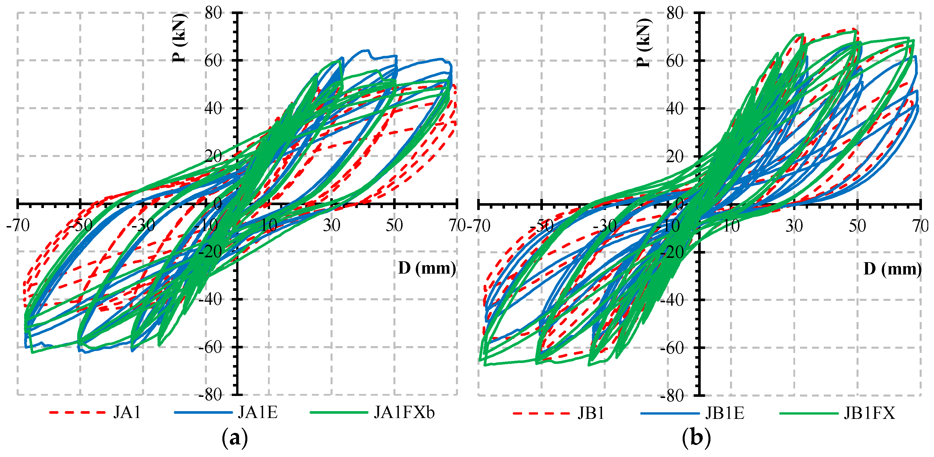
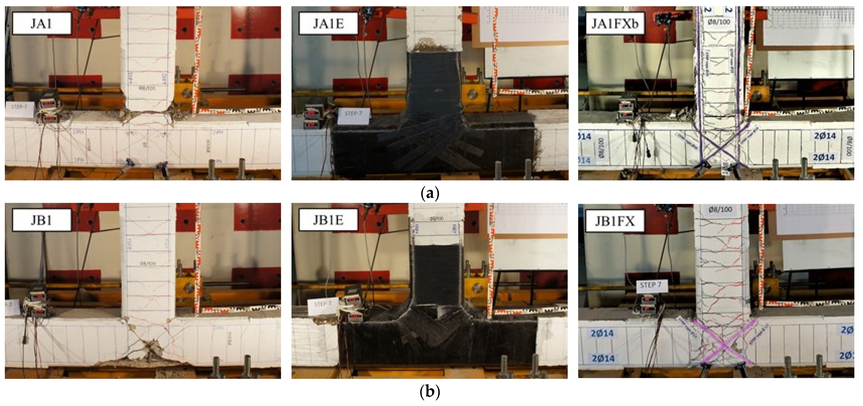
3. Test Results and Hysteretic Response

The load-bearing capacity of the control specimens JA1 and JB1 is compared to the capacity of the repaired JA1E and JB1E and the C-FRP rope reinforced JA1FXb and JB1FX test specimens in order to determine the effectiveness of the rehabilitation method used. Figure 8 displays the test specimens’ hysteretic loops using a force displacement diagram.
The comparison of the test results of group A indicates that the applied rehabilitation approach using C-FRP sheets (JA1E) and C-FRP ropes (JA1FXb) effectively restored the load-bearing capacity of the original joint (Figure 8a). The load-bearing capacity of the rehabilitated test specimen JA1E and the strengthened specimen JA1FXb was considerably higher at each load step than the capacity of the control specimen JA1. The comparison of the group B (Figure 8b) test results reveals that the applied rehabilitation method using C-FRP sheets (JB1E) achieves approximately 85% of the load-bearing capacity of the control specimen JB1. The specimen JB1FX that has been strengthened using C-FRP ropes reaches the load-bearing capacity of the control specimen JB1 after the seventh load step and remains constant afterwards.
The crack patterns that occurred after the end of the tests on the control specimens JA1 and JB1 and on the rehabilitated test specimens JA1E and JB1E, as well as on the strengthened test specimens JA1FXb and JB1FX, are compared in Figure 9. The damage in the control specimen JA1 is mostly observed in the beam area, with only a few cracks appearing in the joint itself. The same mode of failure is observed in the reinforced specimens of Series A. The damage to the joint in this case is considered minor. The damage in the control specimen JB1 occurs mainly in the joint area with intense crosswise cracking and spalling of concrete, while only a few cracks occur in the beam region. The failure mode of the specimen JB1E is also similar, while the specimen JB1FX shows a slightly improved response since there is less disruption in the joint area and more uniform cracking in the beam region.
Figure 10 depicts the stiffness change for the first load levels. The characteristic component stiffness of the control specimen and the test specimen strengthened using the rehabilitation method described above can be compared using the figures. Concerning the specimen of Series A, during the second and the third cycle, both the C-FRP sheet rehabilitated specimen JAE1 and the C-FRP rope strengthened specimen JAFXb1 exhibited a stiffness increase compared to the control specimen JA1. At Story Drift (SD) ratio 1.5%, specimens JA1E and JA1FXb showed higher stiffness values of 14% and 27%, respectively, relative to the control specimen JA1. Beyond the SD ratio of 2%, the specimen JA1FXb presents a slight decrease in stiffness compared to the rehabilitated specimen JA1E but it stills remains about 20% higher than that of the control specimen JA1.
On the other hand, the calculated stiffness of the Series B specimens illustrated a different response. The retrofitted specimen JB1E presents a noticeably lower stiffness compared to the control specimen JB1 during the second and third cycle. This could be attributed to the different failure mode of the specimen JB1, in which the main damage occurred in the joint area and thus rehabilitation could not completely regain the initial stiffness of the specimen, and consequently, the initial stiffness of the rehabilitated specimen JB1E is lower than that of the control specimens.
The stiffness of the strengthened specimen JB1Fxb shows a marginal difference compared to the control specimen JB1 up to a 3% drift ratio; however, after this point, the stiffness of the control specimen degrades rapidly while the strengthened specimen holds a steady decline, indicating that the strengthening method works well and enables the specimen to still resist the applied load.

4. Evaluation of the Test Results
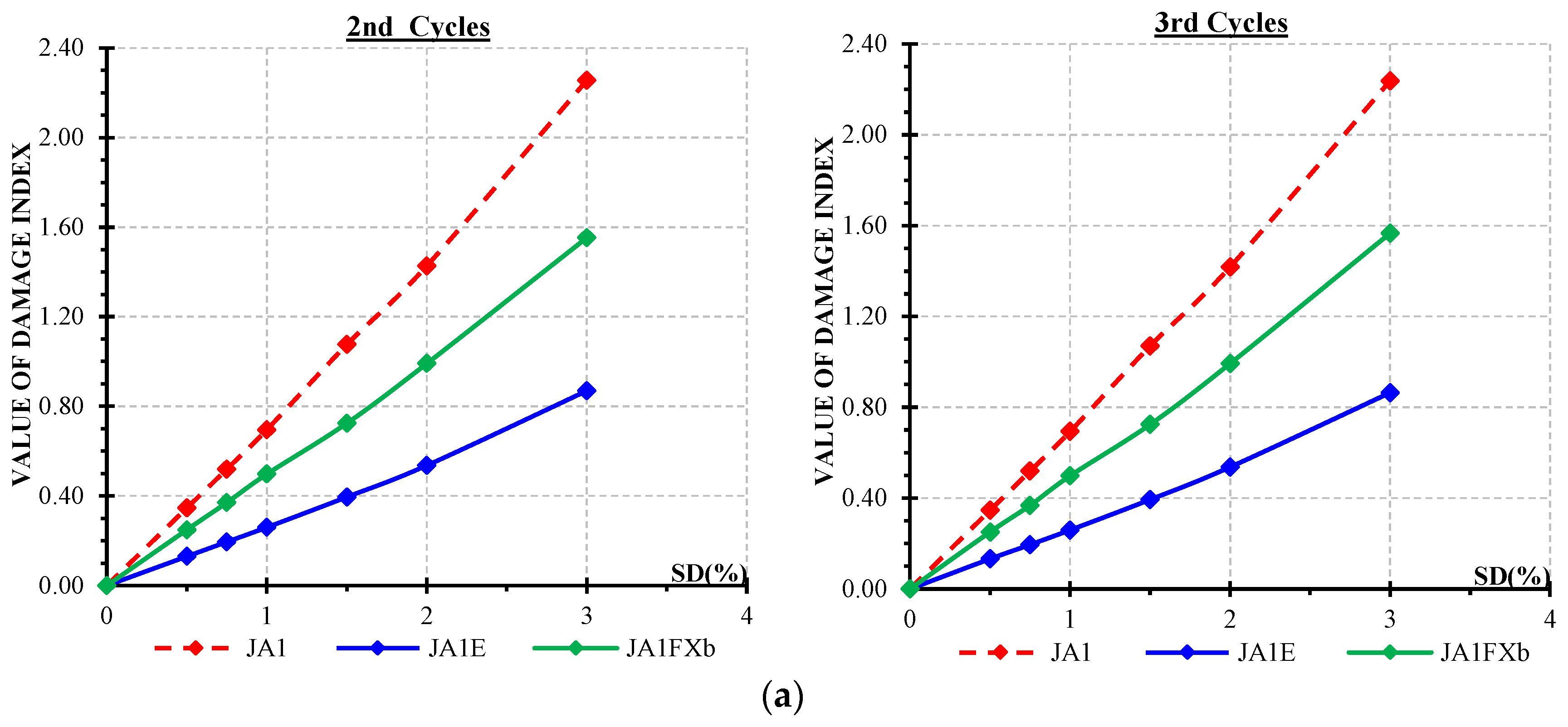
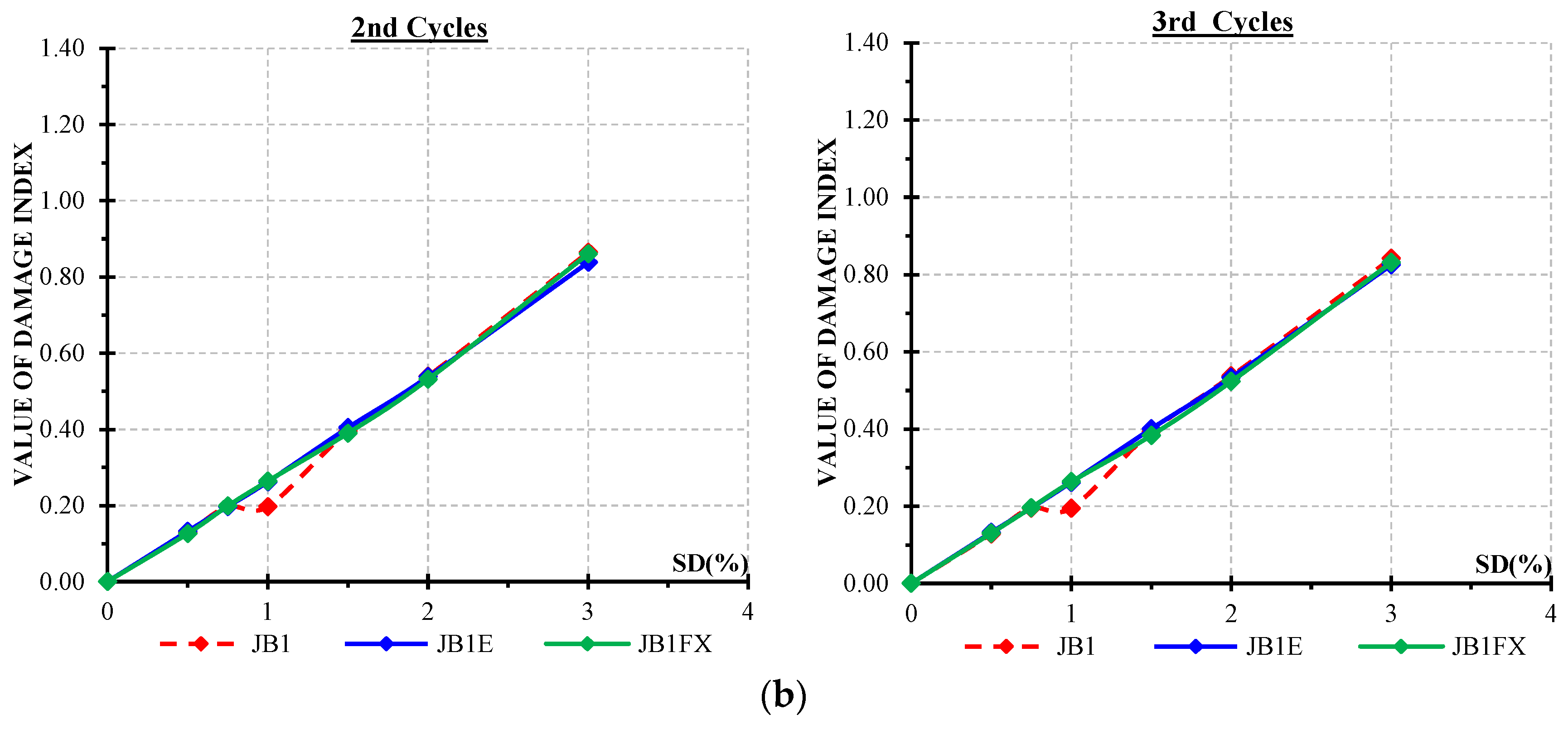
4.1. Damage Index

There are several methods in the literature for measuring the damage of concrete elements after they have been subjected to a load that exceeds the elastic range. The majority of these damage indices are based on the interpretation of deformations and hysteresis curves, as well as information on dissipated energy. Park and Ang’s [75] damage index model has been widely used in recent years due to its simplicity and calibration with experimental data from various structures damaged in past earthquakes. The damage index is defined as the weighted sum of the final displacement and the dissipated energy by the following expression:
D   =   δ M δ u   +   β M y · δ u   d E
where δM represents the maximum deflection, which is reached during the seismic loading. δu is the maximum deformation capacity under static load. β is a model parameter affected by the transverse and normal force values, the quantity of longitudinal reinforcement and the reinforcement setup. My is the calculated yield strength and dE is the increment of the dissipated hysteretic energy.
The damage index model described above is used in this study to draw objective conclusions about the effectiveness of the described rehabilitation method for column-beam joints using C-FRP sheets and to determine the degree of damage in the tested specimens for each individual load step. The values for δM, My and dE of this model were determined based on the test results, while the value of δu was estimated using an empirical formula for calculating the target displacement according to Eurocode 8. Extensive tests have revealed that a value between −0.3 and 1.2 with an average of approximately 0.15 can be used to estimate the coefficient β quantitatively [76]. It should be noted that the value = 0.15 coincides very well with the results of other damage models and has been widely adopted by other researchers [77,78,79]. Figure 11 shows the calculated values of the damage indices for tested specimens using the model described above. In these figures, the damage index values of the control specimens are compared to the damage index values of the corresponding rehabilitated test specimens.
As observed in Figure 11a, during the second and the third cycles, both the retrofitted specimen JA1E and the strengthened JA1FXb exhibited lower values of damage indices compared to the control specimen JA1. Specifically, the repaired specimen JA1E demonstrated the lowest damage index value and this could be attributed to the combined use of the high strength mortar, which limited the crack occurrence, and the C-FRP sheet which provided extra confinement in the joint area and the surrounding beam and column. Figure 11b shows that all three the specimens of Series B, JB1, JB1E and JB1FXb, had almost the same damage index values in both the second and third cycle.

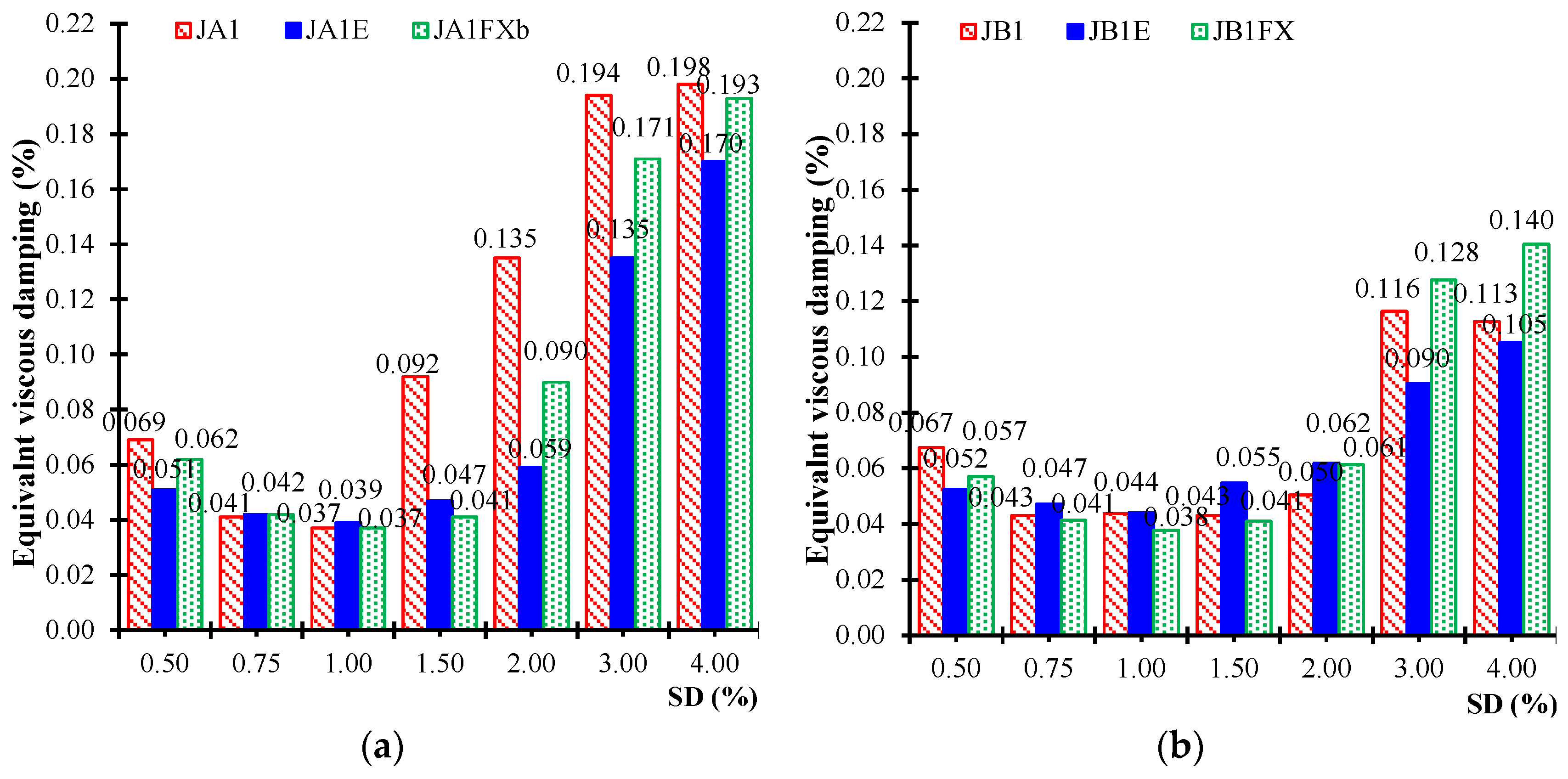
4.2. Equivalent Viscous Damping

In addition to the damage index, the equivalent viscous damping is another indicator of the energy dissipation capacity per load cycle. The value of energy dissipation determines the capacity of the test specimen, which is loaded until failure, and defines the total energy that the test specimen can dissipate before system stability is lost. Plastic deformations that occur outside of the elastic range result in energy dissipation, which can also be described by an equivalent damping. The curve’s path can vary depending on the joint configuration in the column/beam area. The hysteretic damping can be expressed in terms of an equivalent viscous damping ζeq, using an equivalent hysteresis damping ratio:
ζ e q   =   1 4 π · W h y s t W e l
The equivalent viscous damping value ζeq can be used to draw useful conclusions about the efficacy of the rehabilitation technique in terms of restoring the damaged and rehabilitated joints’ energy dissipation ability. The integrals of the dissipated energy are shown in Figure 12 in the form of an equivalent viscous damping. Finally, the viscous damping of the control specimens and the rehabilitated or strengthened test specimens are compared. The first load cycles of all load steps of a total experiment are represented in each case.

5. Conclusions

The effectiveness of strengthening/rehabilitating methods for RC beam-column connections is experimentally investigated. The well-known method of externally bonded C-FRP sheets, as well as the innovative strengthening technique with externally applied C-FRP ropes, are compared. These two techniques are fast and easy to apply, and they preserve the structure’s original dimensions and geometry. The structure’s mass and thus its dynamic properties remain unchanged.
Six full-scale experiments were performed: two control joint specimens, two specimens rehabilitated with C-FRP sheets and two specimens strengthened using C-FRP ropes, and all were subjected to increasing cyclic loading (displacement control). The described strengthening and rehabilitation techniques are effective for restoring the specimens’ performance and both are slightly increasing the load-bearing capacity of existing RC joints on a local level.
The hysteretic performances of the test specimens are compared at each loading cycle. When compared to the control specimens, the C-FRP sheet rehabilitated specimens as well as those strengthened with C-FRP ropes perform better in all cases.
The Park and Ang damage index model is used to assess the progress of the damage level during the tests for all test specimens. The specimens of the group A, which were either rehabilitated C-FRP sheets or strengthened with C-FRP ropes, indicated a significantly improved damage index compared to the control specimens. As a result, the developing damage in the rehabilitated/strengthened joints will be significantly lower than in the control specimens. The damage index is nearly the same in all tests within test group B.
The equivalent viscous damping ratio is also used to calculate the energy consumption of the test specimens. The viscous damping indicator presents the ability of the rehabilitation or strengthening method to restore the energy dissipation capacity of the damaged specimen. The strengthening technique using the C-FRP ropes manages to restore the energy dissipation capacity at a satisfying amount for both series of specimens, A and B. On the other hand, the rehabilitation method using C-FRP sheets restores the energy dissipation capacity in case of small drift values (up to 1.5%), but as the lateral displacement increases, the indicator’s values are significantly lower than those of the corresponding control specimen. This may be attributed to the start of the debonding of the rehabilitation system for larger story drifts.
Both techniques are effective in restoring the joint’s performance. The use of C-FRP ropes as external reinforcement has demonstrated slightly better results. However, it should also be noted that an important advantage of this novel technique is that it requires less intervention in the structure compared to the C-FRP sheets technique; additionally, its application is not affected by the presence of transverse beams. In addition to the abovementioned structural performance assessments, sustainability necessitates a consideration of the economic cost and environmental effects. An economic analysis based on the cost of the retrofitting procedures that have applied to the tested specimens could not be representative or feasible to demonstrate the total real cost of the examined techniques in a quantifiable manner. The direct cost (e.g., materials) of both techniques could be considered more or less the same. However, the indirect cost of the novel fast application using C-FRP ropes is considered to be lower since the interruption in a real-life structure is significantly reduced. In terms of environmental impact, a fast installation and localized rehabilitation will considerably minimize negative environmental effects.
The current research arose to address some preliminary assumptions about the presented novel technique’s application and effectiveness. However, more experimental applications are required to generate additional results and access further information on the performance of the novel strengthening method.

Author Contributions

Conceptualization, C.G.K.; methodology, E.G.; validation, A.G.Z. and G.I.K.; formal analysis, E.G., A.G.Z. and V.K.K.; investigation, E.G., A.G.Z. and G.I.K.; data curation, E.G., A.G.Z. and V.K.K.; writing—original draft preparation, E.G. and A.G.Z.; writing—review and editing, A.G.Z., V.K.K. and C.E.C.; visualization, E.G. and A.G.Z.; supervision, C.G.K. All authors have read and agreed to the published version of the manuscript.

Funding

This research received no external funding.

Institutional Review Board Statement

Not applicable.

Informed Consent Statement

Not applicable.

Data Availability Statement

Data available on request.

Acknowledgments

Author Adamantis G. Zapris gratefully acknowledges the financial support received from the Eugenides Foundation towards doctoral studies.

Conflicts of Interest

The authors declare no conflict of interest.

References

  1. Li, S.; Shan, S.; Zhang, H. Rapid Retrofit of Reinforced Concrete Frames after Progressive Collapse to Increase Sustainability. Sustainability 2019, 11, 4195. [Google Scholar] [CrossRef] [Green Version]
  2. Gil-Martín, L.M.; Rodríguez-Suesca, A.E.; Fernández-Ruiz, M.A.; Hernández-Montes, E. Cyclic Behavior of RC Beam-Column Joints with Epoxy Resin and Ground Tire Rubber as Partial Cement Replacement. Constr. Build. Mater. 2019, 211, 659–674. [Google Scholar] [CrossRef]
  3. Ferreira, T.M.; Rodrigues, H.; Vicente, R. Seismic Vulnerability Assessment of Existing Reinforced Concrete Buildings in Urban Centers. Sustainability 2020, 12, 1996. [Google Scholar] [CrossRef] [Green Version]
  4. Manfredi, V.; Santarsiero, G.; Masi, A.; Ventura, G. The High-Performance Dissipating Frame (HPDF) System for the Seismic Strengthening of RC Existing Buildings. Sustainability 2021, 13, 1864. [Google Scholar] [CrossRef]
  5. Li, S.; Zhang, J. Retrofit Existing Frame Structures to Increase Their Economy and Sustainability in High Seismic Hazard Regions. Appl. Sci. 2019, 9, 5486. [Google Scholar] [CrossRef] [Green Version]
  6. Raza, S.; Khan, M.K.I.; Menegon, S.J.; Tsang, H.-H.; Wilson, J.L. Strengthening and Repair of Reinforced Concrete Columns by Jacketing: State-of-the-Art Review. Sustainability 2019, 11, 3208. [Google Scholar] [CrossRef] [Green Version]
  7. Karayannis, C.G.; Chalioris, C.E.; Sirkelis, G.M. Local Retrofit of Exterior RC Beam–Column Joints Using Thin RC Jackets—An Experimental Study. Earthq. Eng. Struct. Dyn. 2008, 37, 727–746. [Google Scholar] [CrossRef]
  8. Kalogeropoulos, G.I.; Tsonos, A.-D.G.; Konstantinidis, D.; Iakovidis, P.E. Earthquake-Resistant Rehabilitation of Existing RC Structures Using High-Strength Steel Fiber-Reinforced Concrete Jackets. Earthq. Struct. 2019, 17, 115–129. [Google Scholar] [CrossRef]
  9. Tran, M.-T.; Bui, Q.-B.; Sentosa, B.; Nguyen, N.-T.; Duong, T.-H.; Plé, O. Sustainable RC Beam-Column Connections with Headed Bars: A Formula for Shear Strength Evaluation. Sustainability 2018, 10, 401. [Google Scholar] [CrossRef] [Green Version]
  10. Bayhan, B.; Moehle, J.; Yavari, S.; Elwood, K.J.; Lin, S.; Wu, C.; Hwang, S. An Experimental and Analytical Study in Reinforced Concrete Frames with Weak Beam-Column Joints. In Proceedings of the 15WCEE, Lisbon, Portugal, 24–28 September 2012. [Google Scholar]
  11. Bayhan, B.; Moehle, J.; Yavari, S.; Elwood, K.; Lin, S.; Wu, C.; Hwang, S. Seismic Response of a Concrete Frame with Weak Beam-Column Joints. Earthq. Spectra 2015, 31, 293–315. [Google Scholar] [CrossRef]
  12. Kalogeropoulos, G.I.; Tsonos, A.-D.G. Improvement of the Cyclic Response of RC Columns with Inadequate Lap Splices-Experimental and Analytical Investigation. Earthq. Struct. 2019, 16, 279–293. [Google Scholar] [CrossRef]
  13. Mostofinejad, D.; Hajrasouliha, M. 3D Beam–Column Corner Joints Retrofitted with X-Shaped FRP Sheets Attached via the EBROG Technique. Eng. Struct. 2019, 183, 987–998. [Google Scholar] [CrossRef]
  14. Rossetto, T.; Pohoryles, D.; Miranda Melo, J.; Varum, H. The Effect of Slab and Transverse Beams on the Behaviour of Full-Scale Pre-1970’s RC Beam-Column Joints. In Proceedings of the 16th World Conference on Earthquake Engineering, Santiago, Chile, 9–13 January 2017. [Google Scholar]
  15. Yurdakul, Ö.; Avşar, Ö. Strengthening of Substandard Reinforced Concrete Beam-Column Joints by External Post-Tension Rods. Eng. Struct. 2016, 107, 9–22. [Google Scholar] [CrossRef]
  16. Pohoryles, D.A.; Melo, J.; Rossetto, T.; Varum, H.; Bisby, L. Seismic Retrofit Schemes with FRP for Deficient RC Beam-Column Joints: State-of-the-Art Review. J. Compos. Constr. 2019, 23, 03119001. [Google Scholar] [CrossRef] [Green Version]
  17. Bossio, A.; Fabbrocino, F.; Lignola, G.P.; Prota, A.; Manfredi, G. Simplified Model for Strengthening Design of Beam–Column Internal Joints in Reinforced Concrete Frames. Polymers 2015, 7, 1732–1754. [Google Scholar] [CrossRef]
  18. Kam, W.Y.; Quintana Gallo, P.; Akguzel, U.; Pampanin, S. Influence of slab on the seismic response of sub-standard detailed exterior reinforced concrete beam column joints. In Proceedings of the 9th US National and 10th Canadian Conference on Earthquake Engineering: Reaching Beyond Borders, Toronto, ON, Canada, 25–29 July 2010. [Google Scholar]
  19. Tsonos, A.G. Ultra-High-Performance Fiber Reinforced Concrete: An Innovative Solution for Strengthening Old R/C Structures and for Improving the FRP Strengthening Method. WIT Trans. Eng. Sci. 2009, 64, 12. [Google Scholar]
  20. Tsonos, A.G. Seismic Repair of Reinforced Concrete Beam-Column Subassemblages of Modern Structures by Epoxy Injection Technique. Struct. Eng. Mech. Int. J. 2002, 14, 543–563. [Google Scholar] [CrossRef]
  21. Golias, E.; Lindenthal, H.; Schlueter, F.-H.; Karabinis, A.I. Strengthening of Seismically Damaged Reinforced Concrete Beam-Column Joints by Means of FRP Rope Connections through the Joint Area. BAUTECHNIK 2020, 97, 268. [Google Scholar] [CrossRef]
  22. Karayannis, C.G.; Chalioris, C.E.; Sideris, K.K. Effectiveness og RC Beam- Column Connection Repair Using Epoxy Resin Injections. J. Earthq. Eng. 1998, 2, 217–240. [Google Scholar] [CrossRef]
  23. Karayannis, C.; Sirkelis, G. Effectiveness of RC Beam-Column Connections Strengthening Using Carbon-FRP Jackets. In Proceedings of the 12th European Conference on Earthquake Engineering, London, UK, 9–13 September 2002. [Google Scholar]
  24. Karayannis, C.G.; Sirkelis, G.M. Strengthening and Rehabilitation of RC Beam–Column Joints Using Carbon-FRP Jacketing and Epoxy Resin Injection. Earthq. Eng. Struct. Dyn. 2008, 37, 769–790. [Google Scholar] [CrossRef]
  25. Tsonos, A.-D.G.; Kalogeropoulos, G.I.; Iakovidis, P.E.; Konstantinidis, D. Seismic Retrofitting of Pre-1970 RC Bridge Columns Using Innovative Jackets. Int. J. Struct. Eng. 2017, 8, 133–147. [Google Scholar] [CrossRef]
  26. Karayannis, C.G.; Golias, E. Full Scale Tests of RC Joints with Minor to Moderate Seismic Damage Repaired Using C-FRP Sheets. Earthq. Struct. 2018, 15, 617–627. [Google Scholar] [CrossRef]
  27. Wang, B.; Gupta, R. Correlation of Electrical Conductivity, Compressive Strength, and Permeability of Repair Materials. ACI Mater. J. 2020, 117, 53–63. [Google Scholar] [CrossRef]
  28. Wang, B.; Gupta, R. Performance of Repaired Concrete under Cyclic Flexural Loading. Materials 2021, 14, 1363. [Google Scholar] [CrossRef] [PubMed]
  29. Durastanti, C.; Moretti, L. Environmental Impacts of Cement Production: A Statistical Analysis. Appl. Sci. 2020, 10, 8212. [Google Scholar] [CrossRef]
  30. Fujikake, K.; Mindess, S.; Xu, H. Analytical Model for Concrete Confined with Fiber Reinforced Polymer Composite. J. Compos. Constr. 2004, 8, 341–351. [Google Scholar] [CrossRef]
  31. Mahdavi, G.; Nasrollahzadeh, K.; Hariri-Ardebili, M.A. Optimal FRP Jacket Placement in RC Frame Structures Towards a Resilient Seismic Design. Sustainability 2019, 11, 6985. [Google Scholar] [CrossRef] [Green Version]
  32. Sharma, A.; Aneja, S.; Sharma, S.; Gupta, R. Elastic Wave Based Evaluation of CFRP Protected RC Structures Subjected to Corrosion. Constr. Build. Mater. 2021, 287, 123081. [Google Scholar] [CrossRef]
  33. Spadea, G.; Bencardino, F.; Swamy, R.N. Structural Behavior of Composite RC Beams with Externally Bonded CFRP. J. Compos. Constr. 1998, 2, 132–137. [Google Scholar] [CrossRef]
  34. Spadea, G.; Bencardino, F.; Swamy, R.N. Optimizing the Performance Characteristics of Beams Strengthened with Bonded CFRP Laminates. Mater. Struct. 2000, 33, 119–126. [Google Scholar] [CrossRef]
  35. Bencardino, F.; Spadea, G.; Swamy, R.N. Strength and Ductility of Reinforced Concrete Beams Externally Reinforced with Carbon Fiber Fabric. Struct. J. 2002, 99, 163–171. [Google Scholar] [CrossRef]
  36. Spadea, G.; Bencardino, F.; Sorrenti, F.; Swamy, R.N. Structural Effectiveness of FRP Materials in Strengthening RC Beams. Eng. Struct. 2015, 99, 631–641. [Google Scholar] [CrossRef]
  37. Pampanin, S.; Bolognini, D.; Pavese, A. Performance-Based Seismic Retrofit Strategy for Existing Reinforced Concrete Frame Systems Using Fiber-Reinforced Polymer Composites. J. Compos. Constr. 2007, 11, 211–226. [Google Scholar] [CrossRef]
  38. Tsonos, A.G. An Innovative Solution for Strengthening of Old R/C Structures and for Improving the FRP Strengthening Method. Struct. Monit. Maint. 2014, 1, 323–338. [Google Scholar] [CrossRef]
  39. Li, B.; Chua, H.Y.G. Seismic Performance of Strengthened Reinforced Concrete Beam-Column Joints Using FRP Composites. J. Struct. Eng. 2009, 135, 1177–1190. [Google Scholar] [CrossRef]
  40. Attari, N.; Amziane, S.; Chemrouk, M. Efficiency of Beam–Column Joint Strengthened by FRP Laminates. Adv. Compos. Mater. 2010, 19, 171–183. [Google Scholar] [CrossRef]
  41. Li, B.; Kai, Q. Seismic Behavior of Reinforced Concrete Interior Beam-Wide Column Joints Repaired Using FRP. J. Compos. Constr. 2011, 15, 327–338. [Google Scholar] [CrossRef]
  42. Sezen, H. Repair and Strengthening of Reinforced Concrete Beam-Column Joints with Fiber-Reinforced Polymer Composites. J. Compos. Constr. 2012, 16, 499–506. [Google Scholar] [CrossRef]
  43. Ha, G.-J.; Cho, C.-G.; Kang, H.-W.; Feo, L. Seismic Improvement of RC Beam–Column Joints Using Hexagonal CFRP Bars Combined with CFRP Sheets. Compos. Struct. 2013, 95, 464–470. [Google Scholar] [CrossRef]
  44. Kalogeropoulos, G.I.; Tsonos, A.-D.G.; Konstandinidis, D.; Tsetines, S. Pre-Earthquake and Post-Earthquake Retrofitting of Poorly Detailed Exterior RC Beam-to-Column Joints. Eng. Struct. 2016, 109, 1–15. [Google Scholar] [CrossRef]
  45. Tsonos, A.G. Effectiveness of CFRP-Jackets and RC-Jackets in Post-Earthquake and Pre-Earthquake Retrofitting of Beam–Column Subassemblages. Eng. Struct. 2008, 30, 777–793. [Google Scholar] [CrossRef]
  46. Del Vecchio, C.; Di Ludovico, M.; Balsamo, A.; Prota, A.; Manfredi, G.; Dolce, M. Experimental Investigation of Exterior RC Beam-Column Joints Retrofitted with FRP Systems. J. Compos. Constr. 2014, 18, 04014002. [Google Scholar] [CrossRef]
  47. Esmaeeli, E.; Barros, J.A.O.; Sena-Cruz, J.; Fasan, L.; Prizzi, F.R.L.; Melo, J.; Varum, H. Retrofitting of Interior RC Beam–Column Joints Using CFRP Strengthened SHCC: Cast-in-Place Solution. Compos. Struct. 2015, 122, 456–467. [Google Scholar] [CrossRef] [Green Version]
  48. Ghobarah, A.; Said, A. Shear Strengthening of Beam-Column Joints. Eng. Struct. 2002, 24, 881–888. [Google Scholar] [CrossRef]
  49. Realfonzo, R.; Napoli, A.; Pinilla, J.G.R. Cyclic Behavior of RC Beam-Column Joints Strengthened with FRP Systems. Constr. Build. Mater. 2014, 54, 282–297. [Google Scholar] [CrossRef]
  50. Hadi, M.N.S.; Tran, T.M. Retrofitting Nonseismically Detailed Exterior Beam–Column Joints Using Concrete Covers Together with CFRP Jacket. Constr. Build. Mater. 2014, 63, 161–173. [Google Scholar] [CrossRef] [Green Version]
  51. Hadi, M.N.S.; Tran, T.M. Seismic Rehabilitation of Reinforced Concrete Beam–Column Joints by Bonding with Concrete Covers and Wrapping with FRP Composites. Mater. Struct. 2016, 49, 467–485. [Google Scholar] [CrossRef] [Green Version]
  52. Garcia, R.; Jemaa, Y.; Helal, Y.; Pilakoutas, K.; Guadagnini, M. FRP Strengthening of Seismically Deficient Fullscale RC Beam-Column Joints. In Proceedings of the 15th World Conference on Earthquake Engineering, Lisbon, Portugal, 24–28 September 2012. [Google Scholar]
  53. Garcia, R.; Jemaa, Y.; Helal, Y.; Guadagnini, M.; Pilakoutas, K. Seismic Strengthening of Severely Damaged Beam-Column RC Joints Using CFRP. J. Compos. Constr. 2014, 18, 04013048. [Google Scholar] [CrossRef] [Green Version]
  54. Le-Trung, K.; Lee, K.; Lee, J.; Lee, D.H.; Woo, S. Experimental Study of RC Beam–Column Joints Strengthened Using CFRP Composites. Compos. Part. B Eng. 2010, 41, 76–85. [Google Scholar] [CrossRef]
  55. D’Ayala, D.; Penford, A.; Valentini, S. Use of FRP Fabric for Strengthening of Reinforced Concrete Beam-Column Joints. In Proceedings of the 10th International Conference on Structural Faults and Repair, London, UK, 1–3 July 2003. [Google Scholar]
  56. Faleschini, F.; Gonzalez-Libreros, J.; Zanini, M.A.; Hofer, L.; Sneed, L.; Pellegrino, C. Repair of Severely-Damaged RC Exterior Beam-Column Joints with FRP and FRCM Composites. Compos. Struct. 2019, 207, 352–363. [Google Scholar] [CrossRef]
  57. Lee, W.T.; Chiou, Y.J.; Shih, M.H. Reinforced Concrete Beam–Column Joint Strengthened with Carbon Fiber Reinforced Polymer. Compos. Struct. 2010, 92, 48–60. [Google Scholar] [CrossRef]
  58. Fujikake, K.; Soeum, S.; Matsui, T. CFRP Strengthened RC Beams Subjected to Impact Loading. Procedia Eng. 2017, 210, 173–181. [Google Scholar] [CrossRef]
  59. Chalioris, C.E.; Zapris, A.G.; Karayannis, C.G. U-Jacketing Applications of Fiber-Reinforced Polymers in Reinforced Concrete T-Beams against Shear—Tests and Design. Fibers 2020, 8, 13. [Google Scholar] [CrossRef] [Green Version]
  60. Raval, S.S.; Dave, U.V. Effectiveness of Various Methods of Jacketing for RC Beams. Procedia Eng. 2013, 51, 230–239. [Google Scholar] [CrossRef] [Green Version]
  61. Akguzel, U.; Pampanin, S. Analytical Model for Shear Strengthening of RC Beam-Column Joints Using Composite Materials. In Proceedings of the NZSEE Conference, Christchurch, New Zealand, 3–5 April 2009. [Google Scholar]
  62. Akgüzel, U.; Quintana Gallo, P.; Pampanin, S. Seismic Strengthening of a Non-Ductile RC Frame Structure Using GFRP Sheets. In Proceedings of the 9th Pacific Conference on Earthquake Engineering (PCEE 2011): Building an Earthquake-Resilient Society, Auckland, New Zealand, 14–16 April 2011. [Google Scholar]
  63. Roudsari, S.; Hamoush, S.; Soleimani, S.; Abu-Lebdeh, T.; HaghighiFar, M. Analytical Study of Reinforced Concrete Beams Strengthened by FRP Bars Subjected to Impact Loading Conditions. Am. J. Eng. Appl. Sci. 2018, 11, 407–425. [Google Scholar] [CrossRef]
  64. Sharma, S.S.; Dave, U.V.; Solanki, H. FRP Wrapping for RC Columns with Varying Corner Radii. Procedia Eng. 2013, 51, 220–229. [Google Scholar] [CrossRef] [Green Version]
  65. Al-Salloum, Y.A.; Almusallam, T.H. Seismic Response of Interior RC Beam-Column Joints Upgraded with FRP Sheets. I: Experimental Study. J. Compos. Constr. 2007, 11, 575–589. [Google Scholar] [CrossRef]
  66. El-Amoury, T.; Ghobarah, A. Seismic Rehabilitation of Beam–Column Joint Using GFRP Sheets. Eng. Struct. 2002, 24, 1397–1407. [Google Scholar] [CrossRef]
  67. Ghobarah, A.; Said, A. Seismic Rehabilitation of Beam-Column Joints Using FRP Laminates. J. Earthq. Eng. 2001, 5, 113–129. [Google Scholar] [CrossRef]
  68. Antonopoulos, C.P.; Triantafillou, T.C. Experimental Investigation of FRP-Strengthened RC Beam-Column Joints. J. Compos. Constr. 2003, 7, 39–49. [Google Scholar] [CrossRef]
  69. Karayannis, C.G.; Golias, E. Strengthening of Deficient RC Joints with Diagonally Placed External C-FRP Ropes. Earthq. Struct. 2021, 20, 123–132. [Google Scholar] [CrossRef]
  70. Karayannis, C.; Golias, E.; Chalioris, C. Local FRP-Retrofitting of Exterior Reinforced Concrete Beam-Column Joints under Cyclic Lateral Loading. In Proceedings of the 16th European Conference on Earthquake Engineering, Thessaloniki, Greece, 18–21 June 2018. [Google Scholar]
  71. Chalioris, C.E.; Kosmidou, P.-M.K.; Papadopoulos, N.A. Investigation of a New Strengthening Technique for RC Deep Beams Using Carbon FRP Ropes as Transverse Reinforcements. Fibers 2018, 6, 52. [Google Scholar] [CrossRef] [Green Version]
  72. Eurocode 8: Design of Structures for Earthquake Resistance-Part 1: General Rules, Seismic Actions and Rules for Buildings; European Committee for Standardization: Brussels, Belgium, 2005.
  73. American Concrete Institute. Building Code Requirements for Structural Concrete: (ACI 318-02) and Commentary (ACI 318R-02); American Concrete Institute: Farmington Hills, MI, USA, 2002. [Google Scholar]
  74. Tsonos, A.-D.G. Model for the Evaluation of the Beam-Column Joint Ultimate Strength-a More Simplified Version. Earthq. Struct. 2019, 16, 141–148. [Google Scholar]
  75. Park, Y.-J.; Ang, A.H.-S. Mechanistic Seismic Damage Model for Reinforced Concrete. J. Struct. Eng. 1985, 111, 722–739. [Google Scholar] [CrossRef]
  76. Cosenza, E.; Manfredi, G.; Ramasco, R. The Use of Damage Functionals in Earthquake Engineering: A Comparison between Different Methods. Earthq. Eng. Struct. Dyn. 1993, 22, 855–868. [Google Scholar] [CrossRef]
  77. Barros, M.H.F.M.; Martins, R.A.F.; Ferreira, C.C. Tension Stiffening Model with Increasing Damage for Reinforced Concrete. Eng. Comput. 2001, 18, 759–785. [Google Scholar] [CrossRef]
  78. Hafezolghorani, M.; Hejazi, F.; Vaghei, R.; Jaafar, M.S.B.; Karimzade, K. Simplified Damage Plasticity Model for Concrete. Struct. Eng. Int. 2017, 27, 68–78. [Google Scholar] [CrossRef]
  79. Grassl, P.; Jirásek, M. Damage-Plastic Model for Concrete Failure. Int. J. Solids Struct. 2006, 43, 7166–7196. [Google Scholar] [CrossRef] [Green Version]
Figure 1. Geometry and reinforcement characteristics of the beam-column joint specimens: (a) Series A; (b) Series B.
Sustainability 13 06454 g001
Figure 2. Application of the C-FRP sheets on the beam-column joint specimens JA1E and JB1E: (a) detailed schematic representation of arrangement of the C-FRP sheets and (b) rehabilitated specimen.
Sustainability 13 06454 g002
Figure 3. Application of the C-FRP rope on the beam-column joint specimens: (a) JB1FX; (b) JA1FXb.
Sustainability 13 06454 g003
Figure 4. Stages of preparation of the specimens enhanced with application of C-FRP sheets: (a) damaged joint ready for C-FRP sheet application after being shuttered, grouted and cured for 7 days; (b) placing of the C-FRP sheets with detail of the joint region and (c) specimen after application of C-FRP sheets at the final stage.
Sustainability 13 06454 g004
Figure 5. Stages of preparation of the specimens enhanced with application of C-FRP rope.: (a) incision of U-shaped notches; (b) epoxy resin type A application in the notches; (c,d) application of the impregnated C-FRP in the notches; (e,f) notches filament with epoxy resin type B to ensure adhesion between concrete and the fibers of C-FRP rope.
Sustainability 13 06454 g005
Figure 6. Test set-up.
Sustainability 13 06454 g006
Figure 7. Loading sequence with seven loading steps. Each step includes 3 full loading cycles.
Sustainability 13 06454 g007
Figure 8. Hysteretic responses of the tested specimens. Comparative presentation of the original specimen with the corresponding enhanced specimens: (a) Series A and (b) Series B.
Sustainability 13 06454 g008
Figure 9. Final damage mode of the tested specimens (a) Series A and (b) Series B.
Sustainability 13 06454 g009
Figure 10. Observed stiffness of 2 loading cycles in the first loading step. Comparisons between the loading stiffness of the control specimens with the loading stiffness of the enhanced specimens: (a) Series A and (b) Series B.
Sustainability 13 06454 g010
Figure 11. Values of damage index for 2 loading cycles in the first loading step. Comparisons of the damage index values of the control specimen with the damage index values of the enhanced one: (a) Series A and (b) Series B.
Sustainability 13 06454 g011aSustainability 13 06454 g011b
Figure 12. Equivalent viscous damping. Comparisons between the equivalent viscous damping of the control specimen with the equivalent viscous damping of the corresponding enhanced specimens: (a) Series A and (b) Series B.
Sustainability 13 06454 g012
Publisher’s Note: MDPI stays neutral with regard to jurisdictional claims in published maps and institutional affiliations.

