Article

Power Grid Integration and Use-Case Study of Acid-Base Flow Battery Technology

1
Fundación CIRCE, Parque Empresarial Dinamiza, Avenida Ranillas Edificio 3D, 1ª Planta, 50018 Zaragoza, Spain
2
Engineering Department, University of Palermo, Viale delle Scienze Ed. 9, 90128 Palermo, Italy
3
Instituto Universitario de Investigación CIRCE, Universidad de Zaragoza, Edificio CIRCE, Campus Río Ebro, C/ Mariano Esquillor Gómez, 15, 50018 Zaragoza, Spain
4
Instituto Universitario de Investigación CIRCE, Fundación CIRCE, 50018 Zaragoza, Spain
5
S.MED.E Pantelleria S.p.a., Viale Strasburgo 189, 90146 Palermo, Italy
6
AquaBattery B.V., Lijnbaan 3c, 2352 CK Leiderdorp, The Netherlands
*
Author to whom correspondence should be addressed.
Sustainability 2021, 13(11), 6089; https://doi.org/10.3390/su13116089
Submission received: 4 May 2021 / Revised: 23 May 2021 / Accepted: 24 May 2021 / Published: 28 May 2021
(This article belongs to the Special Issue Renewable Energy Technologies and Environmental Impact Assessment)

Abstract

:
There are many different types of energy storage systems (ESS) available and the functionality that they can provide is extensive. However, each of these solutions come with their own set of drawbacks. The acid-base flow battery (ABFB) technology aims to provide a route to a cheap, clean and safe ESS by means of providing a new kind of energy storage technology based on reversible dissociation of water via bipolar electrodialysis. First, the main characteristics of the ABFB technology are described briefly to highlight its main advantages and drawbacks and define the most-competitive use-case scenarios in which the technology could be applied, as well as analyze the particular characteristics which must be considered in the process of designing the power converter to be used for the interface with the electrical network. As a result, based on the use-cases defined, the ESS main specifications are going to be identified, pointing out the best power converter configuration alternatives. Finally, an application example is presented, showing an installation in the electrical network of Pantelleria (Italy) where a real pilot-scale prototype has been installed.

1. Introduction

As the gravity of the climate crisis exerts ever increasing pressure on governments and industries alike, the already rapid acceleration of renewable energy procurement will continue to increase at pace. Fueled by the ever-decreasing cost of distributed energy resources (DER) such as photovoltaic (PV) and wind, it currently seems that a successful rollout of renewables will be boosted by providing cheap energy storage technologies.
Historically, a large proportion of power was generated by the burning of fossils fuels. This method of power generation is highly controllable, making it possible to match supply with demand and to respond to any imbalance in the grid. Given the intermittent nature of renewable energy sources (RES), matching supply with demand becomes a much greater task when renewables make up a significant proportion of the energy mix; however, energy storage systems (ESS) can be used to alleviate some of these problems. It is an unfortunate fact that currently, much of the energy generated by renewables must be discarded due to it being generated at a time when demand is low. Some authors reported that in Germany 4 % of generated wind energy went to waste in 2015, while China discarded 17 % of all its renewable energy generated, due to a lack of sufficient energy storage [1]. Likewise, it is often that the energy generated by renewables is unable to supply the entirety of the load demand. With adequate energy storage integrated within the grid infrastructure, it becomes possible to store excess of renewable energy when supply is high or demand is low and release it when the opposite is true, adding an element of controllability and thus increasing the total amount of load supplied by renewables. In addition, thus, increasing the sustainability of the power grid generation sources by means of increasing the efficiency of the available resources.
There are many different types of ESS available, and the functionalities that they can provide are extensive. However, each of these solutions come with their own set of drawbacks, primarily their high cost. Operational and environmental safety is another important consideration; there is a growing list of incidents that includes explosions and fires that were caused by unstable ESS such as lithium-ion batteries [2] and important ethical concerns over the mining practices employed for the extraction of key minerals such as cobalt [3]. Therefore, a new type of ESS technology has been proposed recently, the acid-base flow battery (ABFB) [4,5] to help in the integration of RES at an affordable cost and in a more sustainable way, based on the acid/base and salinity concentration of water between several tanks.
It is known that electric power can be produced by exploiting the controlled mixing of salt and fresh water via reverse electrodialysis [6] with a high power energy density. Indeed, the energy released by mixing 1 m3 of fresh water in seawater is equivalent to the hydropower that could be obtain in a fall of 270 m. This energy is released because of the increase in entropy when mixing solutions with different salinities, and is converted into electric energy by means of ion-exchange membranes in reverse electrodialysis (RED) [4]. Numerous advances have been made in this technology in the last decade [7].
The main principle is based on the selective transport of cations and ions through ion-exchange membranes (IEMs), resulting in a controlled mixing of salt and fresh water while generating an ionic current. On the other hand, the electrodialysis (ED) is the opposite process in which electricity is used to desalinate brackish water to produce fresh and saltwater [8,9]. Thus, using both methods, RED and ED, results in a system that could be used as an ESS (known as “concentration gradient flow battery”, CGFB).
The ABFB technology proposes to add bipolar membranes (BPM) auxiliary to IEMs to generate not only a salinity gradient, but also a pH gradient [4,10]. A BPM is a composite membrane consisting of oppositely charged ion-exchange layers, preventing theoretically any ion transportation through it. Despite that, ions are provided by water dissociation between the two layers [11]. With this approach, water is dissociated into protons and hydroxyde ions [5]. This extra-action results in 0.83 V per membrane for 1 M acid and base, increasing significantly the voltage that could be obtained by only salinity differences.
Figure 1 shows a scheme of the ABFB technology in which both acid/base and salt/freshwater tanks are pointed out. There are two clearly differentiated processes, charging and discharging. On the one hand, during the charging process, an electric field is applied over the stack producing a dissociation into hydroxyl ions and protons. Additionally, salt is added to a third tank and being carried out across monopolar membranes, an acidic and a basic solution is obtained in one compartment [4].
On the other hand, the discharging process requires an opposite electric field over the stack, producing an electric current flow through an external load, leading to the neutralization of acid and base solutions.
For instance, using a volume of 3 L (using 3 reservoirs of 1 L each) can hold up to 75 kJ (7 kWh/m3), i.e., an energy density significantly higher than pumped hydropower systems (PHSs) and the CGFB [4]. Therefore, the ABFB system offers great potential compared to current state-of-the-art ESS regarding aspects such as safety, costs and sustainability. Consequently, it is necessary to study most-competitive scenarios and how to overcome the power grid integration of such technology.
Consequently, the ABFB technology presents several interesting features. One of the main advantages of ABFB is that it is decoupled between the device rated power and total energy capacity because the first one is set by the membranes’ size and the latter one by the water tanks capacity, resulting in an extremely flexible and modular design. Moreover, the energy and power capability have been boosted thanks to the combination of acid/base concentrations with salt/fresh ones, therefore making the technology more attractive to potential applications. Finally, no gas production inside the ABFB is also advantageous in terms of safety, compared to other battery systems based on electrolysis [12].
Due to the early development stage of ABFB technology, there are few references to this type of batteries in the literature [4]. The technology was first reported in 1983, reporting extremely low efficiencies due to the poor perm-selectivity of the early-stage membranes [13]. In the following decades, research was performed to apply the ABFB concept for a fuel cell application [14]. The developed fuel cell operated with concentrations up to 1 M HCl-NaOH, but the delamination of the BPM caused by the irreversible accumulation of water in the junction of the membrane was observed. From here, several authors [15,16] proposed important improvements such as the salt solution recirculation or techniques to avoid electrolysis in the electrode compartment of the ABFBs and subsequent gas formation. Following, Van Egmond et al. demonstrated the feasibility of the technology, showing stable operation at high current densities during charge (up to 150 A/m2) over a wide pH range, and evaluated the sources of energy losses [17]. Finally, up to date, recent studies have modelled ABFB cells and analyzed the ABFB stack in laboratory conditions [5,14,18,19,20,21].
This work contributes in the development of the ABFB technology by means of providing a study about its most-competitive potential use-cases in order to enable the future market penetration of products based on ABFB technology; moreover, it analyses how to overcome the power grid integration of the technology for the selected use-cases in order to address possible technical limitations for the interconnection of ABFB systems; and finally, it presents the first pilot-scale application example of the ABFB technology to show the feasibility of the technology and current status of development.
This paper is organized as follows. First, Section 2 describes the main characteristics of ABFB technology regarding power integration issues and presents 3 use-cases where the technology could be applied with a good trade-off between cost and functionality. Following, Section 3 describes how to overcome efficiently the power grid integration of this technology describing the features needed by a power converter interface, which is simulated in Section 4. Section 5 describes an application example with a possible implementation of an ESS based on ABFB technology in the electrical network of Pantelleria, Italy. Finally, Section 6 and Section 7 summarize the most important results and conclusions of the research.

2. Competitive Use-Cases Applications for ABFB Technology

To properly define appropriate use-cases for the ABFB system, the strengths and weaknesses of the technology will first be compared to other mainstream ESS solutions. Following, the Smart-Grid Architecture Model (SGAM) will be used to define specific use-cases where it has been determined that the ABFB technology will be able to compete with, or surpass, current ESS solutions.

2.1. Comparing ABFB with Current ESS Solutions

One of the key criteria for an ESS is cost, in terms of both the capital cost (EUR/kWh) and the leveraged cost of storage (LCOS) (EUR/kWh/cycle). Large-scale PHS and compressed-air energy storage (CAES) plants typically have a very large capital cost but a much more acceptable cost per cycle, in the range of 0.05–0.15 EUR/kWh/cycle for PHS, assuming a 25 year lifespan [22,23,24]. These high upfront costs arise from the need for extensive civil engineering works to be carried out to prepare the site, along with expensive turbines and generators to be installed.
Other popular ESS technology is Li-ion batteries. Li-ion has a capital cost of between 150–350 EUR/kWh and a cost per cycle of around 0.30 EUR/kWh/cycle when deployed at small-scale, assuming a 10 year lifespan [25]. These costs are slightly reduced for large-scale deployment and capital costs are generally lower than a PHS or CAES facility of equivalent capacity. On the other hand, the main driver of the cost for Li-ion batteries comes from the price of the chemical storage medium [26]. These costs are unlikely to fall significantly in the future and, although successful research has been carried out to reduce the amount of material needed to produce a Li-ion cell [27], there is a floor to how much cost reduction can be achieved [26].
Vanadium Redox Flow Batteries (VRFB) and metal-air batteries have a capital expenditure (CapEx) that is lower than PHS/CAES but higher than Li-ion, while the cost per cycle is around 0.20 EUR/kWh/cycle with a 15 year lifespan [28]. The ABFB could potentially reach LCOS < 1.5 EUR/kWh/cycle, which is a LCOS higher than other large-scale storage technologies but affordable enough, and considerably cheaper than contemporary smaller-scale solutions. The main costs of the ABFB systems are the membrane materials and the stack; components that are decoupled from the capacity of the system, the cost of the storage medium (water and salt) is marginal in comparison [4]. ABFB, therefore, can compete in terms of cost with the leading technology for large-scale bulk energy storage, and has a favorable cost when compared with smaller-scale ESS.
The space required is another important consideration in the selection of an appropriate ESS. The ABFB system has a theoretical energy density of 7 kWh/m3 which, when operated at the target depth of discharge (DoD) of between 0.2 and 0.8, results in an obtainable energy density >5 kWh/m3 with a relatively high and constant output voltage. Li-ion batteries, in comparison, have a much higher energy density. Indeed, with an energy density between 250–670 kWh/m3, Li-ion batteries have some of the highest energy densities of any battery technology available today [29]. This makes Li-ion technology well suited for storage in situations where space is at a premium, for example in a residential setting or in electric vehicles. This fact is mitigated once an ESS reaches a scale where size is not as much of an issue, for example in commercial or utility-scale projects, as demonstrated by the large footprint required by PHS, which is by far the most extensively deployed large-scale ESS [23]. When comparing ABFB to PHS and CAES it is clear that ABFB holds a major advantage over the other two technologies: a lack of geographical requirement. Both PHS and CAES require very specific geography for their implementation; PHS requires a topography with a significant elevation change while CAES has the geological requirements of large, underground caverns. While a large-scale ABFB system would require a significant amount of space, the system could be installed anywhere where this space is available, without any prerequisite. Furthermore, the overall footprint of the ABFB system can be reduced using tall storage tanks as reservoirs for the storage medium.
Because ABFB is a type of flow battery, its energy capacity is decoupled from its rated power. Moreover, the system is modular, which allows for extra reservoirs to be retrofitted to increase the capacity of a system that has already been commissioned; a trait that is a rare among ESS technologies, including other types of flow batteries. Generally, when a new utility-scale ESS is planned, or replaces a smaller ESS, the size of the system is selected to accommodate for future load growth over a 15–20-year period [28]. This means that for a large amount of the system’s lifetime the full investment is underused, because it is effectively oversized for much of the time, until the planned load growth has occurred. The modularity and standardization of ABFB means that the system can be sized in accordance with the short and medium-term load demand and then retrofitted with more reservoirs to increase the energy capacity as and when needed, allowing for less wasting of investment capital. Because the energy capacity and rated power are decoupled, increasing the capacity in this way would not affect the output of the system; it would just allow for the same power to be produced for a longer period of time.
Operational safety is of primary importance when designing and operating an ESS, and deployment in urban areas or in close proximity to critical grid infrastructure can be hampered because of concerns over safety. Batteries create heat when they are used, and this can become problematic if the conditions are not properly monitored and managed. Many battery technologies, including Li-ion, lead-acid and nickel-based batteries, present a risk of thermal runaway when overcharged [30], which in the worst-case scenario can lead to an explosion. Furthermore, even if an explosion is avoided, thermal runaway can irreparably damage the battery within a very short space of time. Physical damage due to manufacturing defects or improper transportation and installation can be very difficult to detect but can lead to internal short circuits within the cell or the leaking of electrolyte material, which is often toxic and/or flammable [31]; this is both a safety and an environmental hazard. Large-scale PHS introduces a different sort of environmental hazard as the engineering works required to commission one of these power plants can cause extensive ecological and environmental destruction to the surrounding area [32,33], while it has been suggested that CAES projects present a risk of soil contamination [34]. The ABFB technology does not present any of these safety or environmental hazards. Unlike most other batteries, which have storage mediums containing harmful or toxic chemicals such as lead or vanadium, the storage medium of ABFB consists of salt and water, both of which are entirely benign. Furthermore, the salt solutions and electrodes are thermally stable, and no exothermal reactions are involved within the system, meaning that there is no risk of thermal runaway and, because ABFB is a flow battery design, there is no risk presented from overcharging or indeed undercharging. These traits make ABFB particularly well suited for deployment in densely populated areas or in close proximity to essential grid infrastructure, as the safety risk is minimal.
The lifespan of contemporary battery systems is generally quite short, usually within the range of 10–15 years. Metal-ion batteries can suffer from recrystallisation of the storage medium and electrode pulverization while redox flow batteries suffer from crossover of metal ions; all of which cause irreversible degradation and a resulting loss of capacity over time [35,36]. Or other types of chemical batteries, like Pb-A, Ni-Cd, Na-S or NaNiCl2 also presents lifetime expectancy no higher than 15 years in most cases [23,37]. The lifetime of PHS and CAES is much longer, usually around 40–60 years for a PHS facility; however considerable maintenance costs will be incurred over this entire period to keep the installation in good working order. The durability of the ABFB system is very desirable in comparison to these other technologies. There can be no degradation of the storage medium because it only consists of saline solutions of differing concentrations, not composition. ABFB is a closed system, which means that it does not suffer from bio-fouling or colloidal fouling that is often present in open systems, moreover the system is tolerant to contaminants such as dissolved oxygen, or other salts. Fouling can affect both the system efficiency and the lifetime of the system materials; it has been determined through laboratory experiments that the membranes, electrodes and current collectors all have a lifespan of over 10 years due to the controlled environment of the closed system.
Not only operational safety is important but also features such as the availability, the mean time between failures (MTBF), and the failure recovery and management. Fully deployed technologies such as Li-ion have provided extensive studies about this issue [38,39]. However, it is necessary to reach enough maturity level of readiness prior to perform such studies. Therefore, the ABFB technology needs to advance in its development before stablishing the appropriate measures to mitigate or control such contingencies. Nevertheless, due to its modular scheme, as well as because the energy storage capacity (determined by the water tanks) is completely independent from the power capacity (determined by the membrane size), redundancy and complementary components can be added easily to solve this issue.
There are some ESS solutions able to provide extremely short time responses that enable its usage to provide services such as virtual inertia [40]. This is the case for example of supercapacitors energy storage (SCES) [41]. However, the response time of ABFB is too slow to provide services such as primary frequency control, spinning reserve or black start functionality. It is, however, well suited for providing services that do not require such a rapid actuation time. Although the start-up time is relatively slow, the technology can achieve a ramp rate in the region of MW/min, which is enough to provide services such as tertiary frequency control, and non-spinning or supplemental reserve functionality.
Furthermore, environmental impact is also an important issue to be considered in an ESS selection process. For different reasons, PHS, Pb-A and Ni-Cd between others have a strong impact, due to destruction of the landscape, introducing components that suppose a hazard to wildlife or other reasons [24,42]. On the other hand, there are other ESS technologies that introduce a relatively small impact in the environment, such as flywheel energy storage (FES), superconducting magnetic energy storage (SMES). The ABFB technology belongs to the latter technology, since the medium to storage the energy is water.
Finally, Table 1 summarizes the main characteristics of all ESS technologies identified [4,41], and compared them to the ABFB characteristics.

2.2. Smart-Grid Architecture Model

The SGAM [43,44,45,46] provides a structured approach for modelling smart-grid use-cases. Its basis is a three-dimensional framework that is comprised of domains, zones and layers. The domain consists of the components of the traditional electrical energy infrastructure: generation, transmission, distribution, DER and customer premises. The zone describes a typical power system management hierarchy and is detailed further in Table 2.
The domain and zone axes form the component layer, on top of which are placed four interoperability layers: the communication, information, function and business layers.
The function layer describes functions and processes, and is used for mapping out use-cases [47]. Below, three different use-cases for ABFB are established and the relevant SGAM functional layer defined.

2.3. Use-Case 1: Light-Commercial Energy Storage

The objective of light-commercial energy storage use-case [48,49,50] is matching generation to consumption by peak shaving and time-shifting: both energy generation and usage; thus providing a reduction of the businesses’ electricity bills. Flexibility schemes have been discussed widely during the last decade and it is foreseen a change in the power grid paradigm in the following years [51,52]. Therefore, ESS are a key component to provide it in an optimal way and has been discussed widely in the literature [53,54]. The average daily consumption of commercial premises in Europe varies greatly according to the location and function of the premises, along with the country’s climate and gross domestic product (GDP). It is desirable for a light-commercial ESS to have a capacity large enough to cover a full day of demand without needing any additional energy input from the grid or rooftop solar PV. A system with a capacity of 40–70 kWh and rated power of around 5 kW should be enough to cover the daily energy needs of many light-commercial properties, such as a small office building, workshop or shop. When used alongside roof mounted PV panels the system would be able to store any excess energy during times of high generation and release it during times of low generation, providing more autonomy for the user with less reliance on the grid. These grid-connected PV/ESS systems would be equipped with grid following power converters, and functionality would include load shifting and PQ control, as well as the possibility of providing ancillary services to the grid as a constituent of a larger virtual power plant (VPP), providing extra income for the user.
In Figure 2a it can be seen that the function layer of this use-case occurs within the DER and customer premise domains, because the ESS would be situated in commercial premises equipped with rooftop solar PV panels. The zones from process through to enterprise are occupied, indicating that the system encompasses everything from the physical storage device through to the ability to save the user money on their electricity bills; the further market zone for the customer premises represents the opportunities presented by participation in the ancillary services market. Finally, Table 3 summarizes the goals and scope of this use-case.

2.4. Use-Case 2: Low Voltage Network Congestion and Voltage Management

In low voltage network congestion use-cases [49,55,56], multiple ABFB systems would be installed at weak points of the distribution network, such as along radial feeder lines, to add flexibility to the grid, allowing for increased integration of renewables without jeopardizing grid stability. Locating the ESS at distribution level enables network congestion relief as well as allowing for the deferral of upgrades to the distribution network infrastructure. Active power management and frequency regulation can be achieved through peak shaving and active power control while reactive power control allows for voltage management. To promote strategic deployment of the device in locations that could be relatively crowded, such as suburban areas, the capacity of the device should be kept to between 15–45 kWh, with an output power of around 15 kW allowing for between 1–3 h of operation, enough time for the high demand to subside.
In Figure 2b the distribution and DER domains are occupied because the system would be deployed at distribution level. The zones from process through to enterprise are occupied which illustrates that the system provides operational benefit, such as the ability to avoid network congestion, as well as the commercial benefit of distribution network upgrade deferral. Finally, Table 4 summarizes the goals and scope of this use-case.

2.5. Use-Case 3: Bulk Storage to Support Generation

ESS at utility-scale is a widely studied use-case [49,57,58,59]. The installation of a very large ABFB system at the site of generation will enable the facility to deliver a baseload more reliably to the grid, by buffering at times of reduced generation and avoiding the need for expensive “peaker plants” when consumption is high. The capacity of such a system would likely be in the tens or even hundreds of MWh range, corresponding to many thousands of m3 volume for the system’s reservoirs. A power converter with a power output of between 0.5 and 1 MW, which could be used modularly with multiple units in parallel to suit the specific need of the operator, would allow for a wide range of uses. An installation of this size could be operated similarly to a pumped-hydro plant, able to provide power when demand peaks and then recharge when cheaper energy is more abundant. Such an installation could also significantly aid in the continued integration of renewables; due to ABFB’s very low self-discharge rate, a large-scale installation could also be considered for long-term, inter-seasonal energy storage. For example, coupling a utility-scale ABFB ESS with a large PV plant could allow energy to be stored up during the summer months for use during the winter months when solar energy is less available. The advantages of ABFB at this scale are its safety and sustainability characteristics; its modularity and availability of raw materials for mass production; and it is also not limited by the geographical constraints of the former. Moreover, the ABFB technology has a good trade-off capability in terms of energy density and cost. Therefore, a system of this type would also be ideal for use on an island that has limited or no interconnection to a larger grid.
Figure 2c shows that this use-case exists solely across the generation domain, because the system would be deployed at generation level. Zones from process through to operation are occupied, showing that the purpose of the system is to provide operational benefit to the user; there is no commercial benefit other than the avoidance of regulatory penalties, for example from a power outage at times of high demand. Finally, Table 5 summarizes the goals and scope of this use-case.

3. ABFB Power Grid Integration

Typically, the power grid integration of ESS is an important issue to solve to enable its use in power grid support applications, and has been discussed widely in the literature [60,61,62]. Figure 3 shows the main components present in the ESS: the energy storage medium (ESM); the power interface stage; the power grid; the local control system (LCS); the energy management system (EMS); and the utility grid. Thus, the power grid interface provides a link between the ESS and the power grid and facilitates the charging and discharging of the battery on demand.
The design of a power grid interface should generally follow several constraints and requirements: some of them are also specifically related to the technology of the energy source behind the converter to be interfaced to the network. In the case of an electrochemical storage system, it is necessary to assess technological boundaries to avoid damage and degradation and to provide the right functionalities, as well as to establish electrical rated and ranged parameters to fulfil expected requirements. Some of the main battery technologies currently used for energy storage include Li-ion, lead-acid and flow batteries. The ABFB technology is a flow battery and thus has unique characteristics compared to batteries of other battery types.
Hereafter, a brief outline of some specifications for other ESS technologies in use today will be presented first, as it can be still useful to frame the general concepts of the problem. Then, the specific aspects related to the ABFB technology will be presented and discussed, to provide useful indications for the sizing and design of the power converters.

3.1. Sizing of Current ESS Applications in Selected Use-Cases

A brief description and discussion with examples for utility and residential scale specifications for power converters with storage technologies are reported in the following paragraphs. Two different scenarios have been studied, utility-scale and residential applications.

3.1.1. Utility Scale

For utility use, ESS should be scalable and modular, to be able to deploy huge quantities of devices installed in parallel to adapt to every situation. The study has only looked for two types of technologies, Li-ion batteries and VRFB. This has been done for the following reasons: only solutions that need a fully controllable power electronics interface are of interest to the proper sizing of a solution based on ABFB technology; between them, the most popular technologies have been selected. Table 6 shows different examples of ESS solutions scalable to utility-scale size and their specifications.
First, Li-ion battery utility-scale solutions are built up with battery-cell stacks in series until reaching direct current (DC) voltages near the limit of low voltage definition (up to 1300 V [63]), to reduce current and enhance the efficiency of the system. In addition, they provide all-in-one containers in the range of 1 MW and 1 MWh with a scalable solution. Examples of utility-scale plants include a 10 MW/4.3 MWh installation at a thermal plant in southern California to provide supplementary spinning reserve capacity, a 7 MW/7 MWh system in Canada used to balance long duration frequency and voltage irregularities in the transmission system and a 41 MW/41 MWh system that is currently under construction in the UK in order to deliver local grid support by providing capacity and demand charge management [68].
And secondly, the characteristics of flow batteries are dependent on electrolyte type, electrode materials, the electrolyte-membrane interface, stack size, flow rate and temperature, among other factors. By far the most researched type of flow battery is VRFB. VRFB cells produce between 1.2–1.6 V across the membrane and a stack will typically consist of 100 cells [69]. Studies indicate that VRFB systems up to 100 MW are feasible and the technology is used regularly in Japan such as for load levelling at a substation (450 kW, 900 kWh), as auxiliary service in an university (500 kW, 5 MWh), and to stabilize the output of both PV (30 kW, 240 kWh) and wind (170 kW, 1.2 MWh) generators. An example of a 200 kW/400 kWh VRFB consisted of 20 different stacks that were each connected individually to the main DC line through a DC/DC converter [70]. Each stack consisted of 27 bipolar cells, each had an open-circuit voltage of 1.26 V, giving a voltage of 34.02 V across the terminals of the stacks. In [71] an 18.8 kW VRFB cell was developed and could be connected in series to increase the power output. The 18.8 kW cell had a DC voltage of 75.2 V and a DC current of 250 A. A 450 kW example was constructed by placing many cells in series.
Moreover, all ESS solutions usually provide an AC output voltage in the low voltage grid range, around 400 V depending on the country.

3.1.2. Residential Scale

The conventional size of domestic ESS for houses with PV is in the range of 5 kWh [72]. Table 7 shows different domestic ESS solutions and their specifications [73]. As can be seen in the table, most ESS solutions for domestic applications are based on Li-ion batteries or other electrochemical alternatives, mostly because their higher energy density factor. Moreover, the rated power and energy capacity of all of them are quite similar, because the power demands from houses only differ slightly (i.e., energy storage capacity oscillates between 4.8 and 14.5 kWh).

3.2. Sizing Constrains of ABFB Technology

The ABFB technology as flow battery has particular characteristics which must be considered in the process of designing the power converter to be used for the interface with the electrical network. The considerations and the requirements to be taken into account are related to the life cycle of the battery, the target efficiency, the scaling and flexibility of the solution, the guard limitations for the state of charge of the battery, sensitivity to the rate of change of voltages and currents. All these points are discussed in the following paragraphs.

3.2.1. Specific Considerations Related to the Life Cycle of the Battery

The lifetime of the ABFB battery is unknown with accuracy yet due to not a single unit has been manufactured so far, but it is highly likely that the life of the system will be determined by the lifetime of the membranes. In the middle to long run, it is reasonable to aim at a lifetime of at least 10 years for a closed system (with replacement of the membranes every 5–7 years, if necessary). This consideration has a specific impact of the power electronics: the converter should in fact outlive the membranes in terms of lifetime, so it would be recommended to select a power converter with an expected lifespan of more than 10 years.

3.2.2. Specific Requirements to Be Considered in the Power Converter Design

In the design of the direct current/alternating current (DC/AC) power converter, the following considerations should be also taken into account, as they can play a significant role.
  • The power converter should be as efficient as possible.
  • The converter should be designed in such a way that mass production is possible to keep the price per kW as low as possible, so economic considerations are clearly also important.
  • Scaling/multiplication of the solution should be possible. Not all battery systems will have an identical size and therefore it should be possible to change the size of the converter to match the battery size (in terms of kW/MW). In this regard, a modular approach could work, where for instance a standard 100 kW converter could be designed and multiplied in parallel according to customers demand. However, a scaling approach might also be appropriate, where the converter could be redesigned, or parts are expanded to meet demands. Regarding the scaling requirement, the attention should be also focused on the general scale-up of the technology. Large size solutions of hundreds of MW are currently only imagined to be possible in the future: to achieve that, first smaller systems need to be built. Therefore, smaller power converters are necessary. In general, this consideration implies that the sizing of the converters could be planned according to a two-axis approach: the timeline of development of the system (from a few kW up to hundreds of MW) and the scaling of systems according to the batteries built at a certain time (a scale factor of about 10 up/down).
  • In normal charge and discharge mode, the voltage can vary between 0.4 and 1.6 V. However, the battery can undergo a “reset” sequence (“charge reset”) where all solutions are purified in situ so that the solutions are restored to factory settings, extending the lifetime of the battery significantly. The charge reset function requires a minimum voltage of 2 V per ABFB cell at charge current is necessary but preferably an even higher voltage is required, up to 6 V preferably; however, any voltage higher than 6 V adds little value to the functionality. If this leads to fundamental converter design issues making the converter too expensive, a trade-off need to take place between the quality of the reset sequence and the economic considerations mentioned earlier.
  • The ABFB batteries used for the pilot have 56 cells which amounts to a total theoretical open-circuit voltage (OCV) of around 48 V at 100% state of charge (SOC). In the future, for much larger power requirements, it might be possible to switch to high voltage stacks (up to several hundreds of V). This of course will impact the power converter as well. Again, this should be considered when designing the “right converter at the right time”, as discussed above with the considerations about scaling requirements.

3.2.3. Limitations on the State of Charge of the Battery

As with other electrochemical batteries, the ABFB technology would require recommended maximum and minimum limitations on the SOC of the batteries. This corresponds to the definition of two limits, SOCmax and SOCmin, which specify respectively maximum and the minimum SOC allowed for the battery during operation. The definition of the SOC limits varies depending on the battery type and technology, and in the case of ABFB technology, the minimum and the maximum values for the SOC have been stablished between 20–100% at the moment.
This consideration has an impact on the converter design, and it must be reflected in the implementation of the control system of the power converters.

3.2.4. Additional Limitation/Constraints on the Battery Currents

An additional constraint which could be taken into account is the limitation of the currents of the battery. Charge and discharge currents are in fact limited by the stability of the bipolar membrane and the overall internal resistance of the system. At the moment, the current density for charge is limited to about 200 A/m2. Yet in the middle to long run >1000 A/m2 during the charge should be possible. For discharge, at the moment, the maximum current density is about 100 A/m2, starting with low current densities (30 A/m2) to be sure to minimize the risk of damaging the bipolar membranes. In the future, 200 up to 400 A/m2 should be possible if two main obstacles can be overcome: namely lowering the resistivity of the membrane material (also needed for high charge currents) and preventing co-ion leakage to reduce potential losses during discharge.

3.2.5. Sensitivity to the Rate of Change

Under abnormal system conditions such as faults but also in normal operating conditions, voltages, currents and powers can vary rapidly and consistently. It is important then to also assess the possible sensitivity of the storage technology to the steepness of these variations, leading to the definition of specific limits to the rates of change (ramp-rate limiters), which is an important issue that must be considered for both: preventing damage to the unit, and to set the limits of operation of the system. For safety reasons, minimum and maximum ramp-rate limiters should be then included in the overall control and management system of the battery converters. As with the case of state of charge limitations, the considerations regarding the rate limiters are reflected in the design of the control system of the power converters. Van Egmond et al. have reported the behavior of the system describing charge and discharging cycle [17]. However, there is still not enough information regarding ABFB technology about this issue, and hence it should be studied in future research.

3.3. Use-Cases Sizing Specifications

The ABFB battery stack will consist of multiple cells which can be placed both in series and in parallel with each other to reach the desired DC voltage. Currently, the current density of the cells is in the range of hundreds of Amperes per square meter, and the electrical characteristics of the cells will depend upon its design features, especially the size of the membrane.
In the specific case of the pilot built for the Pantelleria island that is described in Section 5, each cell operates at a maximum discharge current of 6 A and a maximum charge current of 8 A. The voltage range for each cell is between 0.4–1.6 V in normal charging/discharging mode; however, the system has a charge reset function to increase the battery lifetime. A reset voltage of 3.3 V was found to be the best trade-off between the efficiency of the reset function and the cost of the power converter. Using these predefined parameters, the stack configuration for each use-case was calculated, shown in Table 8. However, use-case 3 is a utility-scale application, far from the pilot-scale developed operating working point and, therefore, the values achieved do not offer an optimum solution; instead of that, a redesign of the ABFB cells to reduce the number of cells to a reasonable quantity will be preferably.

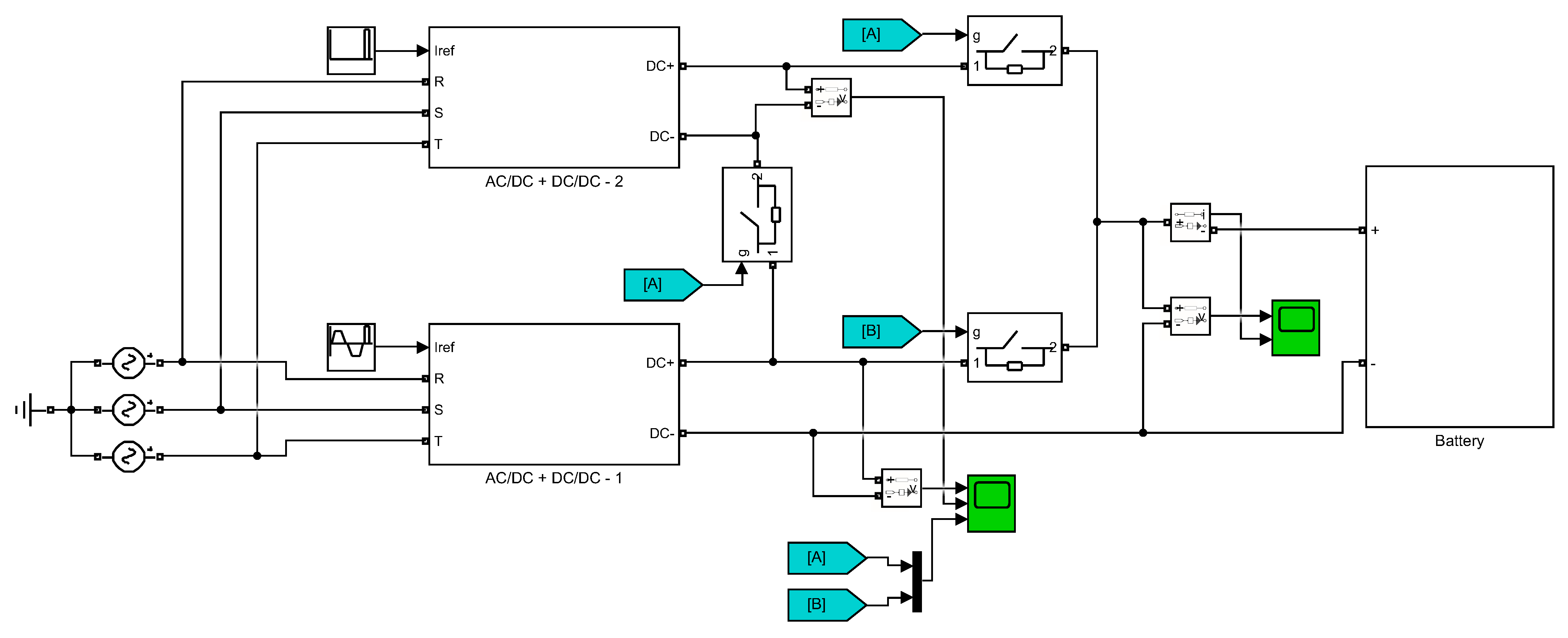
3.4. Power Converter Interface Configuration

In accordance with the design considerations, all three use-cases will use the same basic converter design: a two stage DC/DC–DC/AC converter. This configuration is needed because the low input voltage range at normal conditions, below the minimum rectified AC voltage. Therefore, a first stage will be used to boost the DC voltage and achieve a steady input voltage for the inverter and will consist of an isolated bidirectional DC/DC converter. An isolated DC/DC design is recommended for two reasons: first, because doing so, a low frequency power transformer is not needed in the AC output, saving volume and weight of the unit; and secondly, thanks to this feature, a series association is possible to perform the reset operation, as explained below. Nevertheless, it is possible to use non-isolated DC/DC devices together with low frequency power transformers in the output of each power converter interface if efficiency is critical.
The secondary stage will be a DC/AC converter with a low pass filter, outputting a three-phase AC voltage with the rated low voltage distribution grid voltage and frequency (that values may change in each country).
The maximum DC bus voltage for use-cases 1 and 2 are 850 V which, according to the international standard IEC 60038, is considered to be low voltage (LV) [74]. It is necessary for these use-cases to be classified as LV to avoid the costs from the increased component specification and more stringent regulations associated with higher voltages. The maximum DC voltage for use-case 3 is 1350 V, which is close to the threshold between LV and high voltage (HV), and therefore the components used will be of the higher voltage requirements.
Finally, a scheme of the configuration is presented in Figure 4, in where a switch box has been placed to allow two possible working modes and fulfil Table 8 specifications. First, in case (a) two ABFB devices run in normal operation independently. Afterwards, when the ABFB cells need to be regenerated, the reset working state is activated, as shown in case (b), placing the two power converter interfaces in series to reach the desired input voltage level.

4. Operation of the Power Converter Interface for ABFB Technology

The behavior of two battery modules has been tested through simulation using Matlab and Simulink. For the modelling of the batteries, the parameters described in Table 8 for use-case 2 have been taken into account. For simplicity, only one battery has been simulated and the power converter number 2 is in open circuit; meanwhile the power converter 1 is in normal operation, charging and discharging the battery as Figure 5 shows. When a battery reset is required, the breaker marked with the B-tag opens and A-tag breakers close the circuit to change from a parallel connection to a serial connection, performing the reset process.
The two first graphics of Figure 6 show the battery voltage and current. First, In the time range from t C 0 to t C f the battery is charged by the power converter 1, and afterwards, from t D 0 the system continues to work in normal operation until the simulation reaches t D f discharging the battery. As the third and fourth graphics show, the converter 2 is stopped meanwhile the converter 1 is regulating the voltage to follow the battery current reference. Then, at time t r s t 0 a reset sequence starts. At this moment, the last graphic shows the change in state of the switches to achieve the voltage levels required to perform the reset operation (792 V) without exceeding the breakdown voltage of a single power converter (400 V).

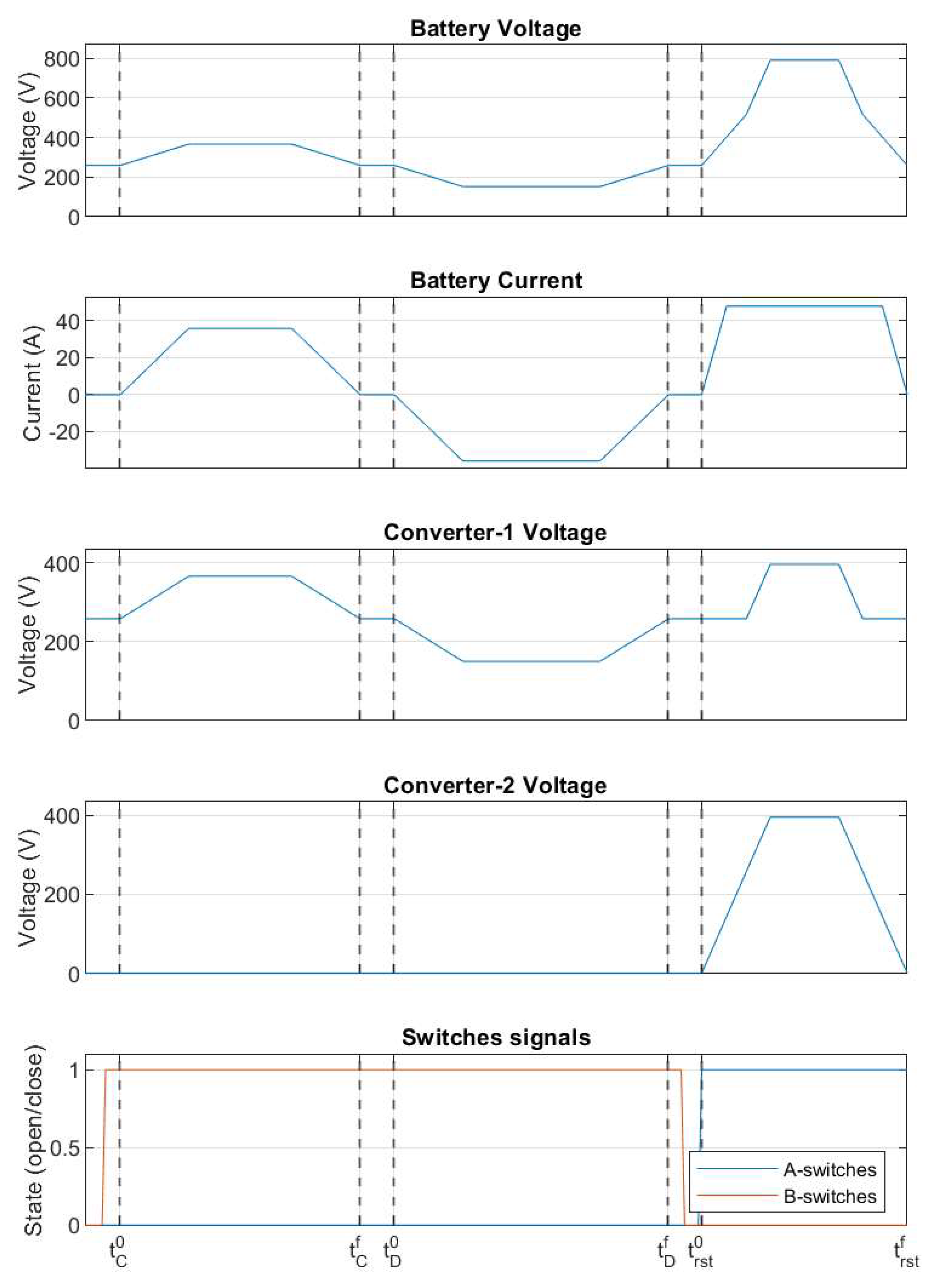
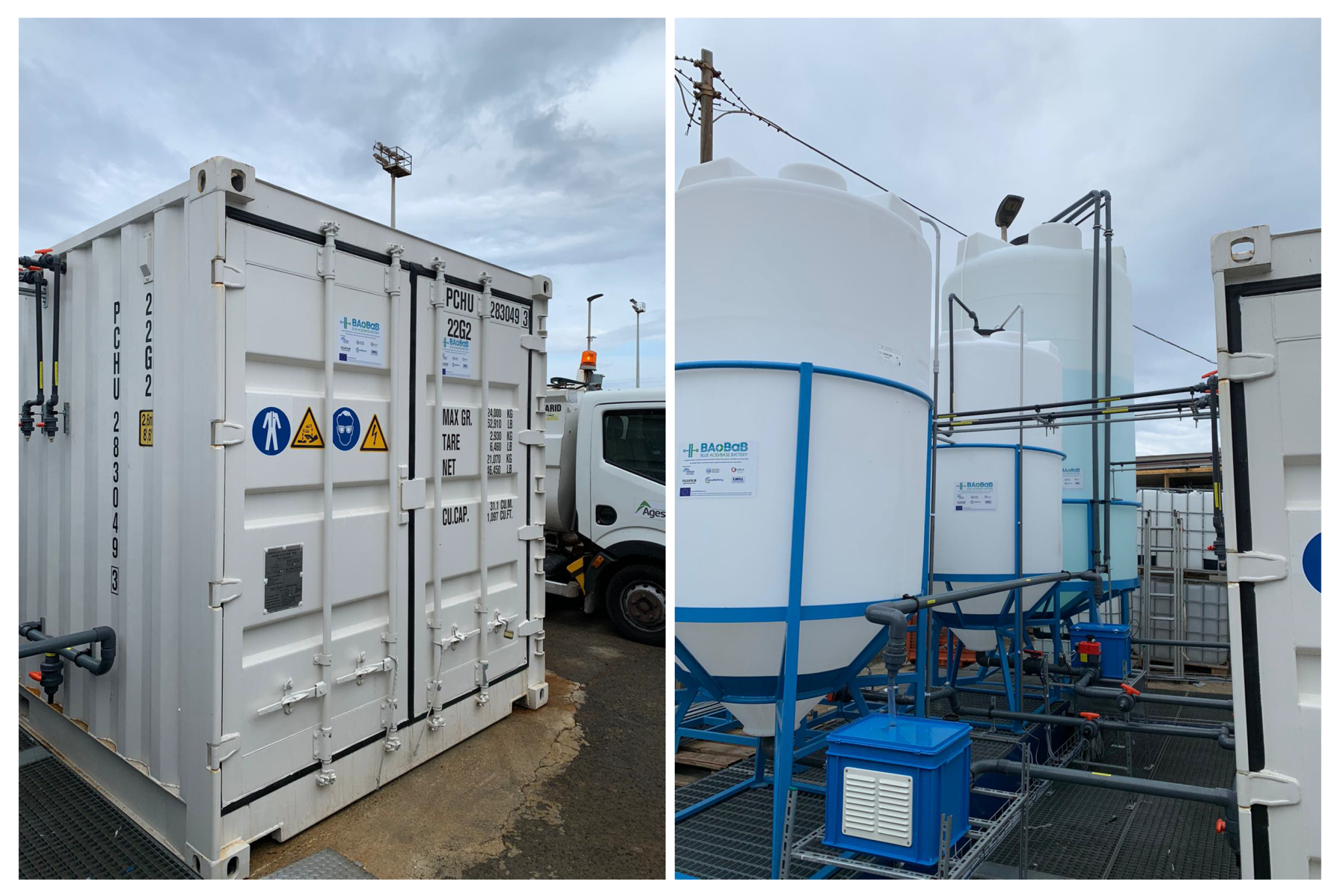
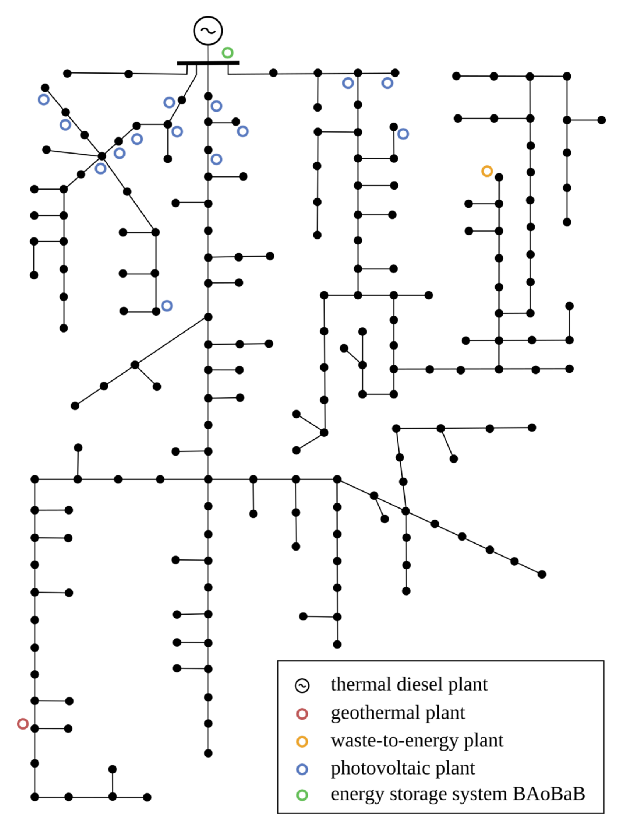
5. Application Example: Implementation in the Electrical Network of Pantelleria

A technology pilot demonstration of 1 kW rated power has been developed in a demo-site located in Pantelleria island (Italy), see Figure 7 [75]. The goal of the installation is to demonstrate the feasibility of this new kind of ESS technology and will be tested in the upcoming months as an ESS at the local power plant, to provide seasonal storage during the high energy demand in summer months. Following, a study about the interconnection of the system with the rest of the island power grid and how it behaves against an analysis regarding power reference step response, transient faults and SOC evolution is shown.
The power system of the island of Pantelleria is a medium voltage network, with a radial structure and the possibility of radially counter-supplying the lines or creating a meshed configuration. Currently, the island is totally dependent on external sources of energy: the supply system relies on a main thermal generation power plant, located close to the urban center of the island. The power plant is composed by eight diesel generators, for a total installed capacity of about 20 MW. The power is delivered to the loads through four main medium voltage feeders, departing from the thermal power plant. The schematic outline of the described system is shown in Figure 8. The green circle denotes the ABFB system installed in the Pantelleria network. Furthermore, Table 9 summarizes the main parameters used for modelling Pantelleria power grid and the blue acid/base battery (BAoBaB) prototype.
The island network including the BAoBaB storage system is analyzed with a positive-sequence RMS dynamic model, implemented in the power systems analysis software NEPLAN. The system is modelled in detail, with particular focus on the dynamic elements of the network such as synchronous machines and regulators, as well as the BAoBaB system with battery and converter control dynamics. For the common dynamic elements such as machines and regulators, the standard built-in models available in the software have been used. For the BAoBaB system instead, the model of the converter system for the DC/AC interface to the network is developed and implemented as user defined dynamic model, formulating the element equations in SYMDEF (SYMbolic DEFinition), the proprietary modelling language of NEPLAN. The dynamic model of the BAoBaB system is developed according to the specifications and the principles specifically selected for the ABFB technology, to reflect in the simulation model the hardware and control design and the characteristics of the power converter system interfacing to the grid of Pantelleria. The storage system is represented as a controlled current source, keeping the power references at the terminal and following the grid variations through a phase-locked loop (PLL). The model implements then a PLL with a synchronous reference frame transformation, two dedicated control loops for the control active and reactive current components, and a current limiter representing the protection of the equipment. The model also implements the specific controls and functionalities for SOC limitations and ramp-rate limiters. The state of charge of the battery system is calculated according to a current integration method (known as Coulomb Counting) including the rated capacity of the BAoBaB storage system in Ah: the calculated value of the SOC is then sent to a block implementing the limitation logic, where the specific limit values of SOCmin and SOCmax specified for the ABFB technology are considered, respectively 20% and 100%. Specific rate limiters are also included in the model of the control system of the ABFB converter, applying them to the command and the reference signals used within the power control loops.
The results of time-domain simulations of the Pantelleria system including the operation of the BAoBaB system in grid-connected mode are reported in the following subsections.

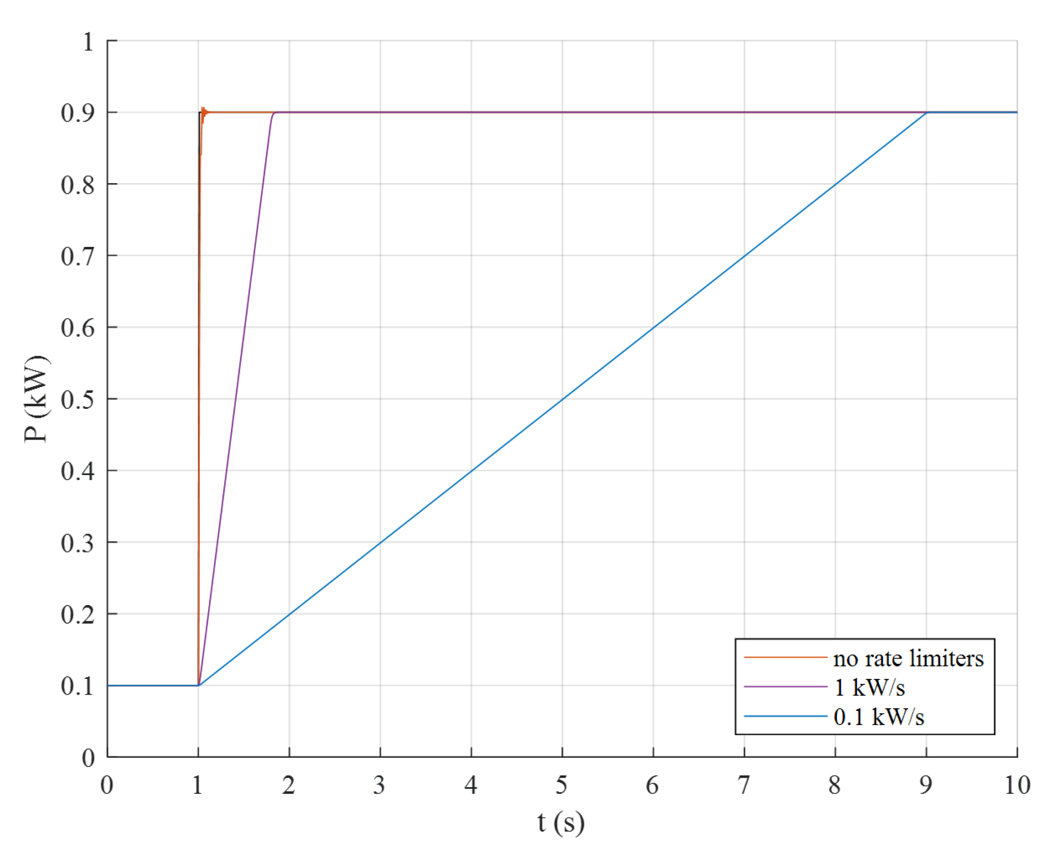
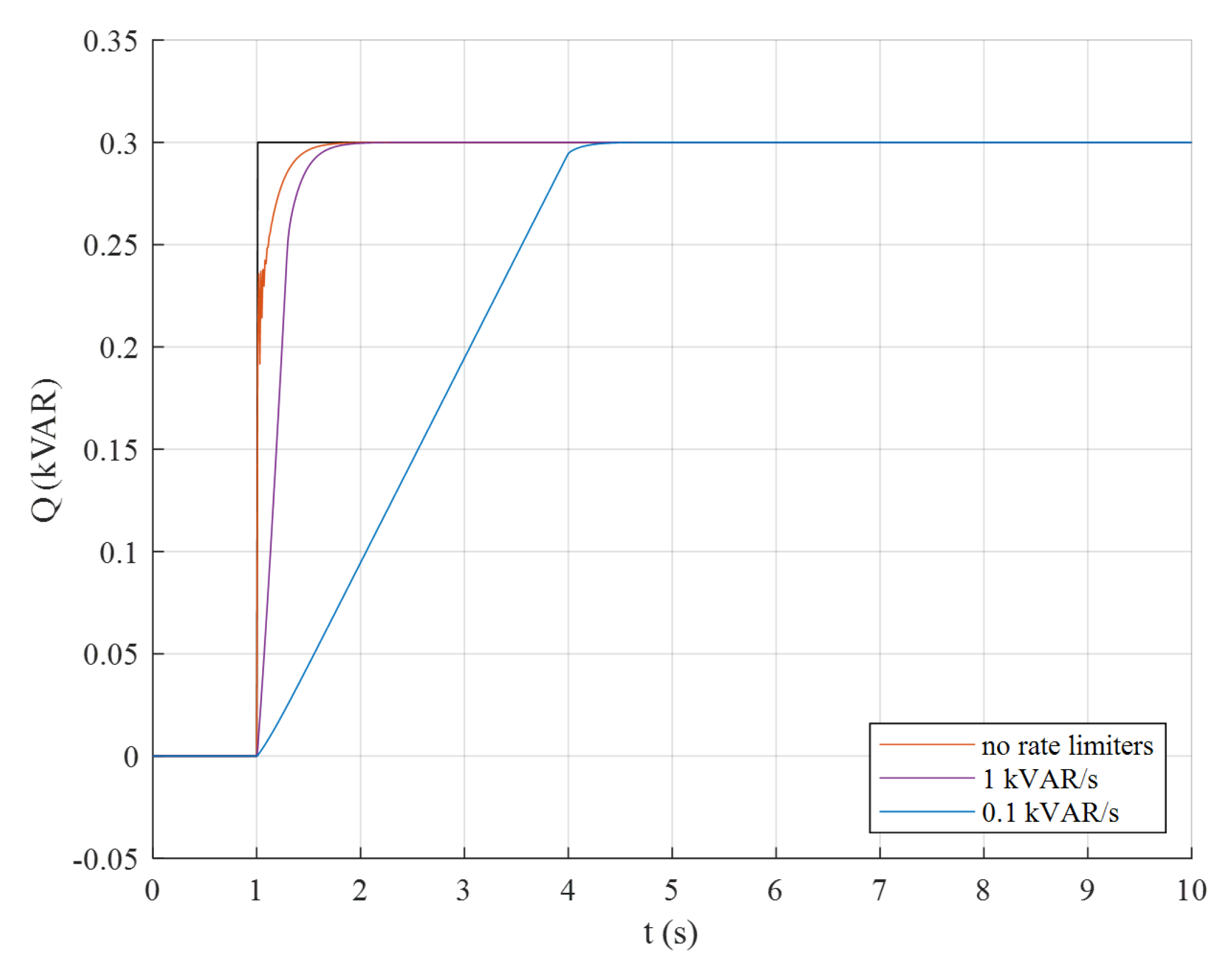
5.1. Step on Power References

In Figure 9, the results for a step response on the active power reference of the converter are shown. The active power is changed from the initial value of 0.1 kW to 0.9 kW, stepping up from 10% to 90% of the rated power of the battery system. Three different cases are considered, to verify the design of the ramp-rate limiters within the converter control. From the results, it is possible to observe that with no rate limiters the converter would be able to follow the reference step almost instantaneously. However, such a fast response might affect the battery and the equipment. Ramp-rate limiters are therefore applied in the control. It can be seen that a limit of 1 kW/s can be already effective in containing the ramping up of the active power provided by the BAoBaB energy storage system, while a limit of 0.1 kW/s might prolong the step response of several seconds.
In Figure 10, the results for a step response on the reactive power reference of the converter are shown. The reactive power is changed from the initial value of 0 kVAR to 0.3 kVAR, stepping up to 30% of the rated power of the battery system. Similar to that done for the step response on the active power, three different ramp-rate limiters are considered in the simulations. A value of 1 kVAR/s appears to be already effective in limiting the ramp of the reactive power provided by the BAoBaB energy storage system, allowing a safe operation of the converter also in this case.

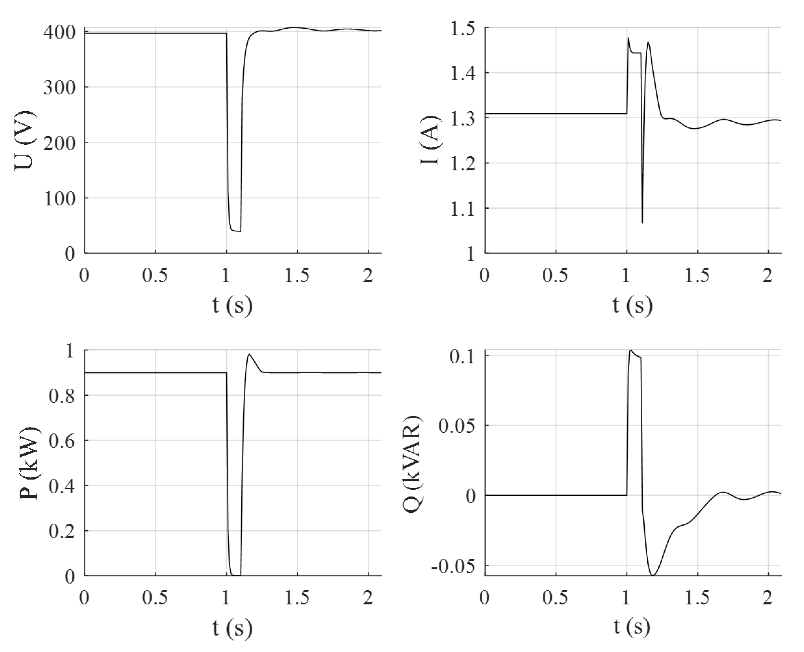
5.2. Terminal Short-Circuit

The results for a 3-phase short-circuit right at the terminal of the BAoBaB storage system are shown in Figure 11. The fault is cleared after 100 ms. For the total duration of the fault, the voltage of the converter drops to a very low value, almost to zero (top-left chart in Figure 11). From the time simulation results, it is possible to appreciate the effects of the current limiters implemented in the converter control as protection of the battery storage system: the magnitude of the current ceils to the given limit imposed by the converter control (top-right chart in Figure 11), and accordingly, the system provides a limited reactive power during the fault (bottom-right chart in Figure 11).

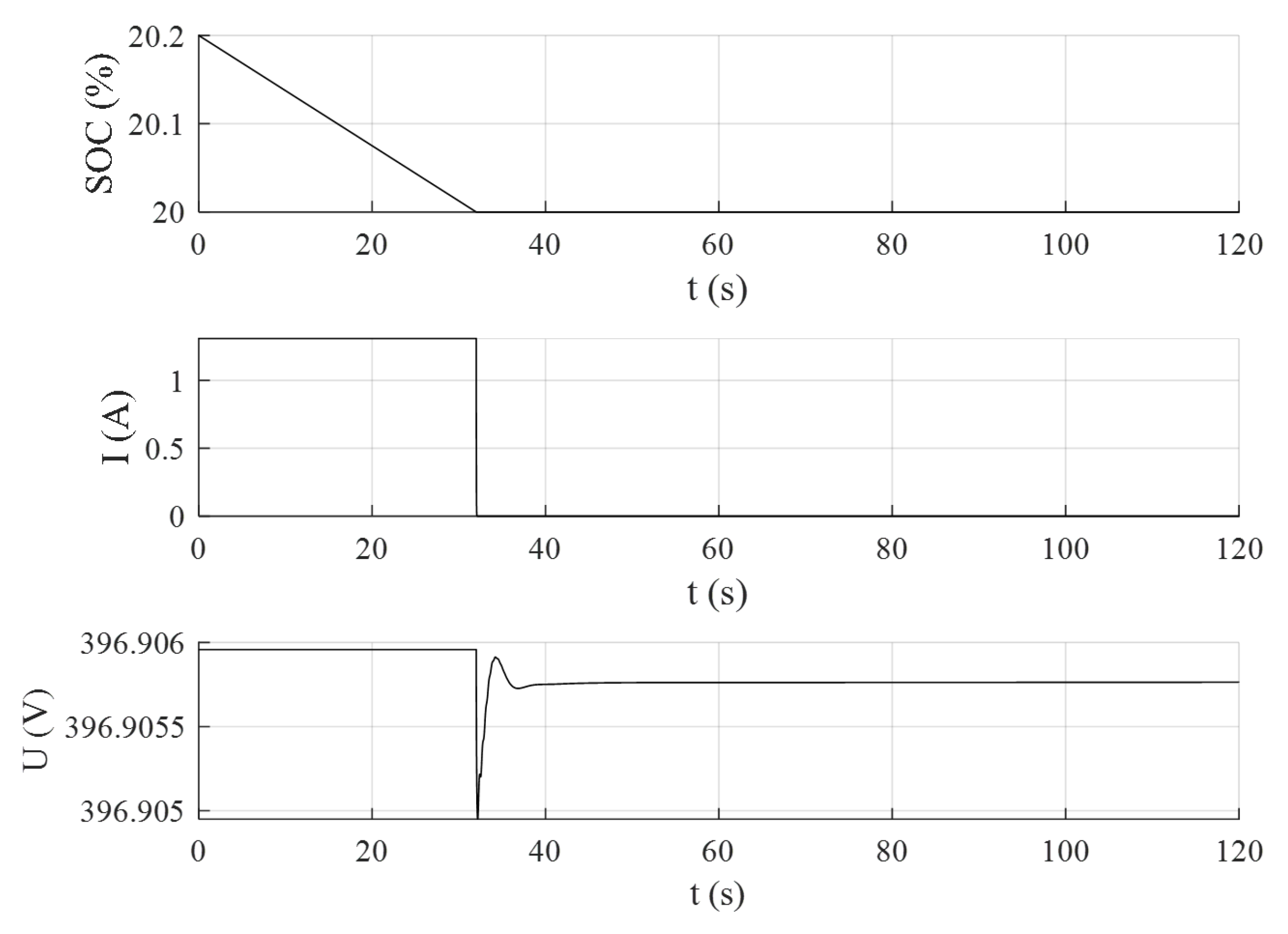
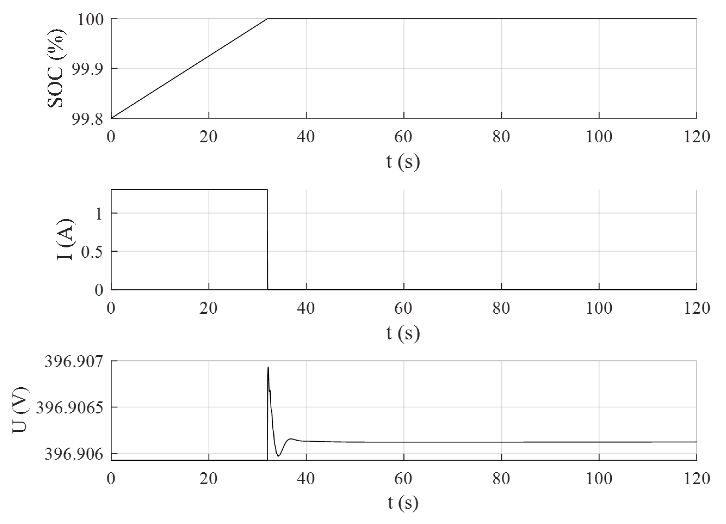
5.3. SOC limitations

The implementation of the SOC limitations within the power converter control is also verified with specific simulations. The results are shown in Figure 12 and Figure 13. In the first case, the BAoBaB system is assumed to be close to the minimum limit SOCmin = 20%, and it is considered to be operating in discharging mode so delivering power to the grid. When the minimum limit is reached, the battery system stops to provide active power to the grid (generated current to zero). In the second case, the storage system is assumed to be in charging mode absorbing power from the grid, close to the maximum limit SOCmax = 100%. When the limit is reached, the battery system quits the charging process and does not request any more power from the grid (absorbed current to zero). The transient response is verified in both simulation cases.

6. Discussion

This paper has analyzed the characteristics and sizing of the power converter and associated ABFB ESS in the commercial and industrial scenarios in which the use of this technology could be advantageous. The ABFB technology has been first compared to other well-known ESS solutions: in Section 2 three use-cases specific for the ABFB system are therefore identified and defined, which are light-commercial energy storage, low voltage network congestions and bulk support to intermittent generation. The power conversion system which should serve as interface of the battery pack to the AC network is then properly designed for application to the ABFB technology: sizing and specifications are derived according to the particular constraints and requirements related to the ABFB technology such as cells configuration, reset sequence voltages, state-of-charge limitations and life cycle preservation.
The specific requirements of each application have been analyzed in Section 3, concluding that use-cases 1 and 2 have similar characteristics, enabling the use of the same power interface, although requiring more parallelization in the second case due to higher rated power capacity. However, applications defined by use-case 3 will require higher working voltages on the DC side, and a higher level of parallelization to reach the desired rated power capacity. Thus, it will be recommended to resize the BPM system for such applications.
Currently, the restoration of electrolyte properties is done by emptying the acid and base tanks in the saltwater tanks and filling them with demineralized water again. To avoid maintenance costs derived from the battery restoration, a connection scheme that allow a change of configuration to allow on-site purification of the salty solutions has been proposed. The main parameters of the Pantelleria pilot battery have been used to simulate the reset operation in Section 4, showing the feasibility of the on-site purification of the solution known as “reset” operation state.
The behavior of two battery modules under charging/discharging normal operation, and in reset state has been shown. The simulation demonstrates how to interconnect the modules to obtain an optimum performance without incurring in significant extra-costs for the development of the power converters; the power converters individually work in the same operation range regardless they are in normal or reset condition.
Finally, Section 4 presents the Pantelleria pilot plant. The goal of the pilot is to demonstrate the feasibility of ABFB technology for seasonal storage. As a first approximation, the island network has been simulated in NEPLAN, where the influence of steps on power references, short-circuit and SOC limitations between the battery and grid have been validated prior to its commissioning.

7. Conclusions

ESS are expected to play a fundamental role in fostering and supporting the integration of power generation from RES. ESS can in fact alleviate some of the problems introduced by high shares of intermittent energy sources, providing a wide range of different services to the grid. To these purposes, the types and the configurations of storage systems which can provide the required functionalities are several, with different nature and characteristics. Every storage technology has natural advantages and disadvantages: among the drawbacks of storage systems, the operation costs and the environmental impact are some of the most relevant. Concerning the sustainability and the impact on the environment, the ABFB technology offers the potential of proving a storage system with the most valuable characteristic of being a cheap, clean and safe storage solution. However, the study has shown that the solution is not the best solution regarding some features: i.e., if the energy density or the response time are critical issues.
Moreover, the power converter topology needed for this application has been described. In particular, a modular approach is proposed, to scale the solution conveniently. Furthermore, the “reset” state condition of the ABFB technology needs to have an extremely large input voltage range. Therefore, this work proposes a two-step modular topology to have an optimum performance in both “normal” and “reset” conditions.
Finally, a prototype of the new ESS technology has been presented in the Pantelleria demo-site. Furthermore, the complete network of Pantelleria island integrating the BAoBaB project pilot system has been implemented and simulated in the software NEPLAN, considering the selected control system for the power converter. The simulation results have shown that the control system is effective allowing a safe operation of the converter under different possible contingencies such as power imbalance and short-circuit which can happen in the network of the island.
Future research will show the behavior of ABFB technology under a real grid scenario, once the commissioning of the plant has concluded, and will determine the feasibility of bringing ABFB technology to higher Technology Readiness Levels (TRL). Furthermore, real data will be used to confirmed or refine current design considerations and use-cases evaluation, enabling a future sensitivity analysis respect to other ESS technologies.

Author Contributions

Conceptualization, J.M.-C.-A., J.B.-F. and R.M.; methodology, J.M.-C.-A., and J.F.S.-O.; simulation, R.M.; formal analysis, J.M.-C.-A. and J.B.-F.; investigation, J.M.-C.-A., J.B.-F., and M.P.J.; resources, J.M.-C.-A., J.B.-F. and R.M.; writing—original draft preparation, J.M.-C.-A., R.M., J.B.-F. and J.F.S.-O.; writing—review and editing, D.M.R.-A., M.P.J., E.G. and A.C.; supervision, J.F.S.-O., D.M.R.-A., E.G. and A.C.; project administration, D.M.R.-A., and A.C. All authors have read and agreed to the published version of the manuscript.

Funding

This work was performed in the framework of the BAoBaB project (Blue Acid/Base Battery: Storage and recovery of renewable electrical energy by reversible saltwater dissociation). The BAoBaB project has received funding from the European Union’s Horizon 2020 Research and Innovation program under Grant Agreement no. 731187 (www.baobabproject.eu, accessed on 26 May 2021).

Acknowledgments

The authors thank to Michele Tedesco from WETSUS, and Alessandro Tamburini from University of Palermo, for his technical assistance and his comments, that greatly improved the manuscript.

Conflicts of Interest

The authors declare no conflict of interest.

References

  1. Bergen, M. Alphabet Wants to Fix Renewable Energy’s Storage Problem—With Salt; Bloomberg Quint: Mumbai, India, 2017. [Google Scholar]
  2. Cooper, J.J. Arizona Fire Highlights Challenges for Energy Storage; The Associated Press: New York, NY, USA, 2019. [Google Scholar]
  3. Frankel, T.C. Cobalt Mining for Lithium Ion Batteries Has a High Human Cost; The Washington Post: Washington, DC, USA, 2016. [Google Scholar]
  4. Pärnamäe, R.; Gurreri, L.; Post, J.; van Egmond, W.J.; Culcasi, A.; Saakes, M.; Cen, J.; Goosen, E.; Tamburini, A.; Vermaas, D.A.; et al. The Acid–Base Flow Battery: Sustainable Energy Storage via Reversible Water Dissociation with Bipolar Membranes. Membranes 2020, 10, 409. [Google Scholar] [CrossRef]
  5. Culcasi, A.; Gurreri, L.; Zaffora, A.; Cosenza, A.; Tamburini, A.; Micale, G. On the modelling of an Acid/Base Flow Battery: An innovative electrical energy storage device based on pH and salinity gradients. Appl. Energy 2020, 277, 115576. [Google Scholar] [CrossRef]
  6. Post, J.W.; Hamelers, H.V.M.; Buisman, C.J.N. Energy Recovery from Controlled Mixing Salt and Fresh Water with a Reverse Electrodialysis System. Environ. Sci. Technol. 2008, 42, 5785–5790. [Google Scholar] [CrossRef]
  7. Mei, Y.; Tang, C.Y. Recent developments and future perspectives of reverse electrodialysis technology: A review. Desalination 2018, 425, 156–174. [Google Scholar] [CrossRef]
  8. Al-Amshawee, S.; Yunus, M.Y.B.M.; Azoddein, A.A.M.; Hassell, D.G.; Dakhil, I.H.; Hasan, H.A. Electrodialysis desalination for water and wastewater: A review. Chem. Eng. J. 2020, 380, 122231. [Google Scholar] [CrossRef]
  9. Campione, A.; Gurreri, L.; Ciofalo, M.; Micale, G.; Tamburini, A.; Cipollina, A. Electrodialysis for water desalination: A critical assessment of recent developments on process fundamentals, models and applications. Desalination 2018, 434, 121–160. [Google Scholar] [CrossRef]
  10. Walther, J.F. Process for Production of Electrical Energy from the Neutralization of Acid and Base in a Bipolar Membrane Cell (U.S. Patent 4,311,771A); International Atomic Energy Agency (IAEA): Vienna, Austria, 1982. [Google Scholar]
  11. Pärnamäe, R.; Mareev, S.; Nikonenko, V.; Melnikov, S.; Sheldeshov, N.; Zabolotskii, V.; Hamelers, H.V.; Tedesco, M. Bipolar membranes: A review on principles, latest developments, and applications. J. Membr. Sci. 2021, 617, 118538. [Google Scholar] [CrossRef]
  12. Sáez, A.; Montiel, V.; Aldaz, A. An Acid-Base Electrochemical Flow Battery as energy storage system. Int. J. Hydrogen Energy 2016, 41, 17801–17806. [Google Scholar] [CrossRef] [Green Version]
  13. Emrén, A.T.; Holmström, V.J. Energy storage in a fuel cell with bipolar membranes burning acid and hydroxide. Energy 1983, 8, 277–282. [Google Scholar] [CrossRef]
  14. Pretz, J.; Staude, E. Reverse electrodialysis (RED) with bipolar membranes, an energy storage system. Berichte Bunsenges. Phys. Chem. 2010, 102, 676–685. [Google Scholar] [CrossRef]
  15. Zholkovskij, E.K.; Müller, M.C.; Staude, E. The storage battery with bipolar membranes. J. Membr. Sci. 1998, 141, 231–243. [Google Scholar] [CrossRef]
  16. Kim, J.H.; Lee, J.H.; Maurya, S.; Shin, S.H.; Lee, J.Y.; Chang, I.S.; Moon, S.H. Proof-of-concept experiments of an acid-base junction flow battery by reverse bipolar electrodialysis for an energy conversion system. Electrochem. Commun. 2016, 72, 157–161. [Google Scholar] [CrossRef]
  17. van Egmond, W.J.; Saakes, M.; Noor, I.; Porada, S.; Buisman, C.J.N.; Hamelers, H. Performance of an environmentally benign acid base flow battery at high energy density. Int. J. Energy Res. 2018, 42, 1524–1535. [Google Scholar] [CrossRef] [Green Version]
  18. Xia, J.; Eigenberger, G.; Strathmann, H.; Nieken, U. Acid-Base Flow Battery, Based on Reverse Electrodialysis with Bi-Polar Membranes: Stack Experiments. Processes 2020, 8, 99. [Google Scholar] [CrossRef] [Green Version]
  19. Veerman, J.; Post, J.W.; Saakes, M.; Metz, S.J.; Harmsen, G.J. Reducing power losses caused by ionic shortcut currents in reverse electrodialysis stacks by a validated model. J. Membr. Sci. 2008, 310, 418–430. [Google Scholar] [CrossRef] [Green Version]
  20. Tang, A.; McCann, J.; Bao, J.; Skyllas-Kazacos, M. Investigation of the effect of shunt current on battery efficiency and stack temperature in vanadium redox flow battery. J. Power Source 2013, 242, 349–356. [Google Scholar] [CrossRef]
  21. Culcasi, A.; Gurreri, L.; Zaffora, A.; Cosenza, A.; Tamburini, A.; Cipollina, A.; Micale, G. Ionic shortcut currents via manifolds in reverse electrodialysis stacks. Desalination 2020, 485, 114450. [Google Scholar] [CrossRef]
  22. Electric Power Research Institute. Quantifying the Value of Hydropower in the Electric Grid: Plant Cost Elements; Technical Report; Electric Power Research Institute: Washington, DC, USA, 2011. [Google Scholar]
  23. Das, C.K.; Bass, O.; Kothapalli, G.; Mahmoud, T.S.; Habibi, D. Overview of energy storage systems in distribution networks: Placement, sizing, operation, and power quality. Renew. Sustain. Energy Rev. 2018, 91, 1205–1230. [Google Scholar] [CrossRef]
  24. Sabihuddin, S.; Kiprakis, A.; Mueller, M. A Numerical and Graphical Review of Energy Storage Technologies. Energies 2014, 8, 172–216. [Google Scholar] [CrossRef]
  25. Few, S.; Schmidt, O.; Offer, G.J.; Brandon, N.; Nelson, J.; Gambhir, A. Prospective improvements in cost and cycle life of off-grid lithium-ion battery packs: An analysis informed by expert elicitations. Energy Policy 2018, 114, 578–590. [Google Scholar] [CrossRef]
  26. Stampatori, D.; Raimondi, P.P.; Noussan, M. Li-Ion Batteries: A Review of a Key Technology for Transport Decarbonization. Energies 2020, 13, 2638. [Google Scholar] [CrossRef]
  27. Horie, H. Future Lithium-ion Batteries. In Future Lithium-ion Batteries; Eftekhari, A., Ed.; Royal Society of Chemistry: London, UK, 2019; Chapter 7—Creatio; p. 367. [Google Scholar] [CrossRef]
  28. Mongird, K.; Fotedar, V.; Viswanathan, V.; Koritarov, V.; Balducci, P.; Hadjerioua, B.; Alam, J. Energy Storage Technology and Cost Characterization Report; Technical Report July; U.S. Department of Energy: Washington, DC, USA, 2019.
  29. Chen, J. Lithium-Ion Battery; Clean Energy Institute: Seattle, WA, USA, 2020. [Google Scholar]
  30. Belov, D.; Yang, M.H. Failure mechanism of Li-ion battery at overcharge conditions. J. Solid State Electrochem. 2008, 12, 885–894. [Google Scholar] [CrossRef]
  31. Doughty, D.; Roth, E.P. A general discussion of Li Ion battery safety. Electrochem. Soc. Interface 2012, 21, 37–44. [Google Scholar] [CrossRef] [Green Version]
  32. Normyle, A.; Pittock, J. A review of the impacts of pumped hydro energy storage construction on subalpine and alpine biodiversity: Lessons for the Snowy Mountains pumped hydro expansion project. Aust. Geogr. 2020, 51, 53–68. [Google Scholar] [CrossRef]
  33. Kobler, U.G.; Wüest, A.; Schmid, M. Effects of lake-reservoir pumped-storage operations on temperature and water quality. Sustainability 2018, 10, 1968. [Google Scholar] [CrossRef] [Green Version]
  34. Liu, W.; Ramirez, A. State of the art review of the environmental assessment and risks of underground geo-energy resources exploitation. Renew. Sustain. Energy Rev. 2017, 76, 628–644. [Google Scholar] [CrossRef]
  35. Deng, D. Li-ion batteries: Basics, progress, and challenges. Energy Sci. Eng. 2015, 3, 385–418. [Google Scholar] [CrossRef]
  36. Perry, M.L.; Saraidaridis, J.D.; Darling, R.M. Crossover mitigation strategies for redox-flow batteries. Curr. Opin. Electrochem. 2020, 21, 311–318. [Google Scholar] [CrossRef]
  37. Aneke, M.; Wang, M. Energy storage technologies and real life applications—A state of the art review. Appl. Energy 2016, 179, 350–377. [Google Scholar] [CrossRef] [Green Version]
  38. Scarabaggio, P.; Carli, R.; Cavone, G.; Dotoli, M. Smart control strategies for primary frequency regulation through electric vehicles: A battery degradation perspective. Energies 2020, 13, 4586. [Google Scholar] [CrossRef]
  39. Maheshwari, A.; Paterakis, N.G.; Santarelli, M.; Gibescu, M. Optimizing the operation of energy storage using a non-linear lithium-ion battery degradation model. Appl. Energy 2020, 261, 114360. [Google Scholar] [CrossRef]
  40. Toma, L.; Sanduleac, M.; Baltac, S.A.; Arrigo, F.; Mazza, A.; Bompard, E.; Musa, A.; Monti, A. On the virtual inertia provision by BESS in low inertia power systems. In Proceedings of the 2018 IEEE International Energy Conference, ENERGYCON 2018, Limassol, Cyprus, 3–7 June 2018; pp. 1–6. [Google Scholar] [CrossRef] [Green Version]
  41. Behabtu, H.A.; Messagie, M.; Coosemans, T.; Berecibar, M.; Fante, K.A.; Kebede, A.A.; Van Mierlo, J. A review of energy storage technologies’ application potentials in renewable energy sources grid integration. Sustainability 2020, 12, 10511. [Google Scholar] [CrossRef]
  42. Rohit, A.K.; Rangnekar, S. An overview of energy storage and its importance in Indian renewable energy sector: Part II—Energy storage applications, benefits and market potential. J. Energy Storage 2017, 13, 447–456. [Google Scholar] [CrossRef]
  43. Smart Grid Coordination Group. Smart Grids Methodology and New Applications; Technical Report; CEN-CENELEC-ETS: Brussels, Belgium, 2014. [Google Scholar]
  44. Uslar, M.; Delfs, C.; Gottschalk, M. The Use Case and Smart Grid Architecture Model Approach; Springer: Berlin, Germany, 2017; pp. 41–61. ISBN 978-3319492285. [Google Scholar]
  45. Santodomingo, R.; Uslar, M.; Göring, A.; Gottschalk, M.; Nordstrom, L.; Saleem, A.; Chenine, M. SGAM-based methodology to analyse Smart Grid solutions in DISCERN European research project. In Proceedings of the ENERGYCON 2014—IEEE International Energy Conference, Cavtat, Croatia, 13–16 May 2014; pp. 751–758. [Google Scholar] [CrossRef]
  46. Andrén, F.P.; Strasser, T.; Kastner, W. Applying the SGAM methodology for rapid prototyping of smart Grid applications. In Proceedings of the IECON 2016—42nd Annual Conference of the IEEE Industrial Electronics Society, Florence, Italy, 23–26 October 2016; pp. 3812–3818. [Google Scholar] [CrossRef]
  47. Wilker, S.; Meisel, M.; Sauter, T. Smart grid architecture model standardization and the applicability of domain language specific modeling tools. In Proceedings of the 2017 IEEE 26th International Symposium on Industrial Electronics (ISIE), Edinburgh, UK, 19–21 June 2017; pp. 152–157. [Google Scholar] [CrossRef]
  48. Liu, J.; Zhang, N.; Kang, C.; Kirschen, D.; Xia, Q. Cloud energy storage for residential and small commercial consumers: A business case study. Appl. Energy 2017, 188, 226–236. [Google Scholar] [CrossRef] [Green Version]
  49. Malhotra, A.; Battke, B.; Beuse, M.; Stephan, A.; Schmidt, T. Use cases for stationary battery technologies: A review of the literature and existing projects. Renew. Sustain. Energy Rev. 2016, 56, 705–721. [Google Scholar] [CrossRef]
  50. Ballestín-Fuertes, J.; Muñoz-Cruzado-alba, J.; Sanz-Osorio, J.F.; Laporta-Puyal, E. Role of wide bandgap materials in power electronics for smart grids applications. Electronics 2021, 10, 677. [Google Scholar] [CrossRef]
  51. Cochran, J.; Miller, M.; Zinaman, O.; Milligan, M.; Arent, D.; Palmintier, B.; O’Malley, M.; Mueller, S.; Lannoye, E.; Tuohy, A.; et al. Flexibility in 21st Century Power Systems; Technical Report; NREL: Golden, CO, USA, 2014. [CrossRef]
  52. Akrami, A.; Doostizadeh, M.; Aminifar, F. Power system flexibility: An overview of emergence to evolution. J. Mod. Power Syst. Clean Energy 2019, 7, 987–1007. [Google Scholar] [CrossRef] [Green Version]
  53. Sperstad, I.B.; Korpås, M. Energy storage scheduling in distribution systems considering wind and photovoltaic generation uncertainties. Energies 2019, 12, 1231. [Google Scholar] [CrossRef] [Green Version]
  54. Scarabaggio, P.; Grammatico, S.; Carli, R.; Dotoli, M. Distributed Demand Side Management with Stochastic Wind Power Forecasting. IEEE Trans. Control. Syst. Technol. 2021. [Google Scholar] [CrossRef]
  55. van Westering, W.; Hellendoorn, H. Low voltage power grid congestion reduction using a community battery: Design principles, control and experimental validation. Int. J. Electr. Power Energy Syst. 2020, 114, 105349. [Google Scholar] [CrossRef]
  56. Agbonaye, O.; Keatley, P.; Huang, Y.; Bani Mustafa, M.; Hewitt, N. Design, Valuation and Comparison of Demand Response Strategies for Congestion Management. Energies 2020, 13, 6085. [Google Scholar] [CrossRef]
  57. Pavić, I.; Luburić, Z.; Pandžić, H.; Capuder, T.; Andročec, I. Defining and evaluating use cases for battery energy storage investments: Case study in Croatia. Energies 2019, 12, 376. [Google Scholar] [CrossRef] [Green Version]
  58. Muñoz-Cruzado-Alba, J.; Rojas, C.A.; Kouro, S.; Díez, E.G. Power production losses study by frequency regulation in weak-grid-connected utility-scale photovoltaic plants. Energies 2016, 9, 317. [Google Scholar] [CrossRef] [Green Version]
  59. International Renewable Energy Agency. Utility-Scale Batteries Innovation Landscape Brief; IRENA: Abu Dhabi, United Arab Emirates, 2019. [Google Scholar]
  60. Torres, J.; Blanco, M.; Lafoz, M.; Navarro, G.; Nájera, J.; Santos-Herran, M. Dimensioning methodology of energy storage systems for power smoothing in a wave energy conversion plant considering efficiency maps and filtering control techniques. Energies 2020, 13, 3380. [Google Scholar] [CrossRef]
  61. Daud, M.Z.; Mohamed, A.; Hannan, M.A. A review of the integration of energy storage systems (ESS) for utility grid support. Prz. Elektrotechniczny 2012, 88, 185–191. [Google Scholar]
  62. Chang, L.; Zhang, W.; Xu, S.; Spence, K. Review on Distributed Energy Storage Systems for Utility Applications. CPSS Trans. Power Electron. Appl. 2017, 2, 267–276. [Google Scholar] [CrossRef]
  63. General Electric. GE Energy Storage Unit RSU-4000; Technical Report January; General Electric: Boston, MA, USA, 2020. [Google Scholar]
  64. Megapack|Tesla. Available online: https://www.tesla.com/megapack (accessed on 5 April 2021).
  65. Utility ESS—BYD USA. Available online: https://en.byd.com/energy/utility-ess/ (accessed on 5 April 2021).
  66. Vanadium Flow Battery Energy Storage|Invinity. Available online: https://invinity.com/solutions/vanadium-flow-batteries/ (accessed on 2 April 2021).
  67. Redox Flow Battery|Sumitomo Electric Industries. Available online: https://sumitomoelectric.com/products/redox (accessed on 7 April 2021).
  68. Energy, S.; Inverter, S. GE Energy Storage Reservoir Inverter Unit; Technical Report; General Electric: Boston, MA, USA, 2021. [Google Scholar]
  69. Lotspeich, C. A Comparative Assessment of Flow Battery Technologies. In Proceedings of the 2002 EESAT Conference, San Francisco, CA, USA, 15–17 April 2002; pp. 1–6. [Google Scholar]
  70. Bryans, D.; Amstutz, V.; Girault, H.H.; Berlouis, L.E. Characterisation of a 200 kw/400 kwh vanadium redox flow battery. Batteries 2018, 4, 54. [Google Scholar] [CrossRef] [Green Version]
  71. Tokuda, N.; Kanno, T.; Hara, T.; Shigematsu, T.; Tsutsui, Y.; Ikeuchi, A.; Itou, T.; Kumamoto, T. Development of a redox flow battery system. SEI Tech. Rev. 2000, 50, 88–94. [Google Scholar]
  72. Marra, F.; Yang, G.; Træholt, C.; Østergaard, J.; Larsen, E. A decentralized storage strategy for residential feeders with photovoltaics. IEEE Trans. Smart Grid 2014, 5, 974–981. [Google Scholar] [CrossRef] [Green Version]
  73. Solar Battery Storage: Including Tesla Powerwall, LG Chem, Powervault. Available online: https://nakedsolar.co.uk/storage/ (accessed on 2 April 2021).
  74. International Electrotechnical Commission. IEC 60038: IEC Standard Voltages; Technical Report; IEC: Geneva, Switzerland, 2002. [Google Scholar]
  75. Technology|BAoBaB. Available online: http://www.baobabproject.eu/technology (accessed on 26 June 2020).
Figure 1. ABFB scheme: 4 tanks with different characteristics are used: acidic, base, salt, and fresh water. Two types of BPMs are used for the charge and discharge process, the BPM ED and BPM RED, respectively [4].
Sustainability 13 06089 g001
Figure 2. The SGAM functional layer defined for all defined use-cases: residential use-case 1 (a); low voltage network congestion use-case 2 (b); and bulk storage to support generation use-case 3 (c). All SGAM zones (market, enterprise, operation, field, and process) are correlated with the SGAM domains: generation (G), transmission (T), distribution (D), DER, and customer premises (C).
Sustainability 13 06089 g002
Figure 3. Main elements involved in the integration of an ESS: ESM; power interface stage; power grid; LCS; EMS; and the utility grid.
Sustainability 13 06089 g003
Figure 4. Proposed modular two-step topology for power converter interface of ABFB technology applications. The system is built up by an isolated DC/DC converter together with a 3-phase power inverter (or a single phase depending on the sizing of the system). (a) represents a configuration in which 2 modules are connected independently in “normal” operation, and (b) points out a serial configuration of the DC/DCs to perform the reset state upon one of the ABFB stacks.
Sustainability 13 06089 g004
Figure 5. Simulation environment: the power converters are parallel connected during charge and discharge, when a reset process is required, both converters are series connected to achieve a higher working voltage.
Sustainability 13 06089 g005
Figure 6. Simulation results, from top to bottom: battery voltage, battery current, converter-1 voltage, converter-2 voltage, switch control signals.
Sustainability 13 06089 g006
Figure 7. BAoBaB 1 kW prototype installed in Pantelleria island.
Sustainability 13 06089 g007
Figure 8. Network scheme of Pantelleria island, with integration of the BAoBaB technology.
Sustainability 13 06089 g008
Figure 9. Active power output for a step on active power reference from 10% to 90%.
Sustainability 13 06089 g009
Figure 10. Reactive power output for a step on reactive power reference from 0% to 30%.
Sustainability 13 06089 g010
Figure 11. Simulation results of a 3-phase short-circuit at the storage system terminal.
Sustainability 13 06089 g011
Figure 12. SOC limitations on the storage system for minimum value 20%.
Sustainability 13 06089 g012
Figure 13. SOC limitations on the storage system for maximum value 100%.
Sustainability 13 06089 g013
Table 1. Technical characteristics of typical ESS compared with ABFB technology. Data from [41].
ESSPower Range (MW)Energy Density (Wh/L)Power Density (W/L)Round Trip eff. (%)Response Time (ms-h)Lifetime (year)Daily Self-Discharge (%)Tech. MaturityCAPEX (EUR/kW)CAPEX (EUR/kWh)Environ. Impact
PHS10–50000.5–1.50.5–1.570–85min40–60≃0.0Full dev.1–3 k5–100High/ Med.
FES0–0.2520–801–2 k90–95s1524–100Mature250–3501–5 kVery low
CAES5–5003–60.5–270–90min20–40≃0.0Proven400–8002–120Med./ Low
Pb-A0–3050–8010–40070–9010 ms3–150.1–1.1Full dev.300–600200–400High
Ni-Cd0–3060–150150–30060–9020 ms10–200.1–0.7Full dev.0.5–2 k0.8–2 kHigh
Na-S0–3150–250150–23080–901 ms10–1520Proven1–3 k300–500High
NaNiCl20–3150–180220–30085–90<s10–1412–26Proven150–300100–200Med./ Low
Li-ion0–100200–5000.5–2 k85–10020 ms5–150.1–0.3Proven0.9–4 k0.6–3 kMed./ Low
VRFB0.3–320–700.5–275–90s5–10smallProven0.6–2 k0.2–1 kMed./ Low
SCES0–0.32.5–150.5–5 k90–1008 ms200.5–40Proven100–4800.3–2 kVery Low
SMES0.1–100.2–2.51–4 k95–100<100 ms201–15Proven200–4901–10 kLow
ABFB0.01–0.5717 W/m2 (*)55.9s10smallPilot152050Very Low
(*) ABFB’s energy density is related to the total membrane’s area size.
Table 2. The power system management hierarchy represented by the zones in the SGAM model. Data from [44].
ZoneRepresentation
ProcessRepresents the transformation of energy (physical, spatial and chemical) and the physical equipment that is directly involved, such as PV panels, generators, transformers and cables.
FieldIncorporates the equipment that is required to collect, control, monitor or protect the process of the power system, such as sensors, controllers and smart devices.
StationDenotes the aggregated level of the field zone, such as a local Supervisory Control and Data Acquisition (SCADA) system.
OperationProvides power system control operations in the respective domain, e.g., an energy management system (EMS) in generation and transmission systems.
EnterpriseIncludes commercial and organizational processes, services and infrastructures for enterprises, e.g., asset management, logistic, customer relation management, billing and procurement.
MarketIndicates potential market operations along the energy conversion chain, such as energy trading or ancillary services.
Table 3. Summary of the scope and objectives of Use-case 1.
Scope and Objectives of Use-Case 1
ScopeThere is a growing trend for installation of rooftop PV. Supplementary to this, installing an ESS allows the user to store excess energy generated from the PV panels for times of higher demand or lower generation, thus reducing their reliance on the grid and subsequently reducing their electricity bills. Further value can be provided to the user by promoting the localized trading of energy via a centralized ESS.
Objectives
  • Match generation to consumption by time-shifting energy use and peak shaving.
  • Increase customers’ self-consumption.
  • Decrease energy bills by reducing reliance on the energy grid, enabling participation in the ancillary services market and promoting localized energy trading.
Table 4. Summary of the scope and objectives of Use-case 2.
Scope and Objectives of Use-Case 2
ScopeStrategic deployment of ESS at distribution level and close to locations with high load demand, such as residential areas, can reduce congestion at weak points in the network and adds flexibility to the grid. Network support functionality allows for increased penetration of renewables without compromising grid stability.
Objectives
  • Reduction of congestion in the distribution network during times of high load demand.
  • Network support through control of active power, voltage and frequency.
  • Enable increased penetration of renewables without jeopardizing the stability of the grid.
  • Deferral of upgrades to the distribution network infrastructure.
Table 5. Summary of the scope and objectives of Use-case 3.
Scope and Objectives of Use-Case 3
ScopeThe intermittent nature of renewables is an obstacle to the provision of a reliable baseload to the grid. Furthermore, seasonal variations in generation means that excess energy is often wasted at one point of the year while generation falls short at another time of the year. A cheap, large-scale ESS solution can store energy during times of excess generation and provide a buffer during times where generation falls short of demand.
Objectives
  • Advance the ability of renewables to provide coverage for the baseload of the grid.
  • Provide a buffer for renewables for times of high demand or lower generation.
  • Reduce the need for “peaker” plants.
  • Inter-seasonal storage.
Table 6. Specifications of some examples of utility-scale ESS solutions.
Utility-Scale Storage SystemTechnologyCharge/ Discharge (kW)Storage Capacity (kWh)
GE RSU-4000 [63]Li-ion13004184
Tesla Powerpack [64]Li-ion1264.52529
BYD Utility ESS [65]Li-ion10001000
Invinity VS3-022 [66]VRFB78220
Sumimoto 250 kW-6 h [67]VRFB2501500
Table 7. Specifications of some examples of commercial ESS domestic solutions.
Residential Battery Storage SystemCharge/ Discharge (kW)Storage Capacity (kWh)Useable Capacity (kWh)
Tesla Powerwall513.513.5
SolarEdge LG Chem RESU 1059.89.3
Puredrive Energy Storage 9.6 kWh3.6/4.29.68.8
Powervault 3–12.3 kWh3.3/5.512.312.3
Powervault 3–8.2 kWh3.3/5.58.28.2
Sonnen 9.43–15 kWh3.31513.5
Sonnen 9.43–7.5 kWh3.37.56.75
Alpha Smile 14.5 kWh314.513.92
Solis/BYD 7 kWh375.6
Puredrive Energy/Solis Hybrid 5 kWh34.84.4
Moixa 4.8 kWh2.44.83.84
Varta Pulse 62.3/2.56.55.9
Solax Hybrid X1 Triplepower 6.3 kWh1.76.35.67
Table 8. The ABFB proposed stack parameters calculated for each defined use-case according to the BPM cells developed in the pilot.
ABFB Stack Parameters
Use-case123
Number of ABFB cells in series240240310
Number of ABFB stacks in parallel26205
Minimum operating voltage96 V96 V124 V
Maximum operating voltage384 V384 V496 V
RESET voltage792 V792 V1023 V
Charge current12 A36 A1230 A
Discharge current−16 A−48 A−1640 A
Rated power12.7 kW38 kW1678 kW
Maximum output power4.6 kW13.8 kW610.1 kW
Table 9. Parameters used to model Pantelleria demo-site.
BAoBAB Prototype
ParameterValueUnits
Rated power1kW
Minimum state of charge20%
Maximum state of charge100%
Maximum power rate limit1pu/s
Minimum power rate limit−1pu/s
Control mode of active poweropen-loop-
Control mode of reactive powerclose-loop-
Active power control time constant0.01s
Reactive power control proportional gain1pu
Reactive power control integral gain10pu
Terminal voltage control proportional gain2pu
Terminal voltage control integral gain0pu
Converter time constant0.01s
Converter PLL bandwidth30rad/s
Pantelleria Power Grid
Power plant rated capacity20MW
Power plant inertia constant2s
Power plant frequency droop5%
Length range of medium voltage feeders4–14km
Resistance range of medium voltage feeders0.33–0.47Ω /km
Reactance range of medium voltage feeders0.23–0.31Ω /km
Capacitance range of medium voltage feeders0.1–0.24μF/km
Publisher’s Note: MDPI stays neutral with regard to jurisdictional claims in published maps and institutional affiliations.

