1. Introduction
In many parts of the world, including Europe, design of new buildings for earthquake resistance is a relatively recent development. In many regions, resistance of buildings to lateral forces resulted in the past only from wind considerations. Provisions for seismic design and detailing of members and structures resembling those found in modern seismic codes did not appear before the mid-1970s in US standards, or the mid-1980s in European national codes. Therefore, in the light of current knowledge, the building heritage of many seismic regions worldwide is largely substandard and seismically deficient [
1].
According to the fib bulletin 24 [
2], as reported in [
3], the seismic retrofit intervention in reinforced concrete (RC) buildings can be classified as local, at member level, or global, at structural level.
The most common interventions at member level are:
- -
Fibre reinforced polymers or textiles embedded in mortar or in cementitious matrix wrapping to infill RC frame or members [
4];
- -
Steel jacketing, steel plate or profiles bonded on the perimeter of the RC member [
5];
- -
RC jacketing to increase of the member’s cross section by adding new concrete [
6].
The seismic retrofit interventions at the structural level are mainly:
- -
Steel bracing consists in the installation of diagonal steel braces in some bays connected to the existing RC members, increasing the strength and dissipation capacity of the structure [
7,
8];
- -
Exterior buttress/exoskeleton consists in the addition of lateral resisting structural systems outside the building, and it reduces the level of forces insisting on the existing building [
9,
10];
- -
RC wall addition by infilling strategic bays to control the lateral drift and the damage to structural and non-structural components;
- -
Regarding retrofitting techniques that involve the use of an exoskeleton, there are two innovative techniques recently published. The first one, with dual function of insulation and seismic improvement, develops a seismic coat composed of a thin reinforced concrete slab thrown inside a cast consisting of two layers of insulating material, bound to the existing structure by metal connectors [
13,
14,
15]. The second technique uses the external lattice steel of diagrid structures, that can efficiently absorb the shear forces produced by horizontal actions [
16].
In addition, existing buildings are characterized by a high thermal insulation deficit, mainly due to the legislative delay in adopting appropriate design criteria. The demand for passive thermal performance has grown significantly in recent years as regulations have gradually aligned with global targets with the Kyoto Protocol.
The building integrated retrofit can be an innovative technological solution that allows to increase both the seismic and energy performance [
3,
17].
This technique should consider not only the effectiveness in terms of seismic and energy performance, but also aspects related to the use of natural materials with low embedded emissions to improve other aspects like the life cycle assessments of the structures and lower the carbon footprint of the retrofitting intervention.
Within this context, a global structural retrofit system, which could be easily integrated in a more complex structural-energetic one, is proposed to guarantee seismic improvement through the use of an unconventional sustainable material like bamboo.
Bamboo has a high carbon sequestration ability, which could lead to even a possibly negative carbon footprint of bamboo products as reported by the INBAR report [
18,
19]. Replacing high CO
2 emitting materials like metals, plastic or concrete with bamboo could lead to a high CO
2 reduction.
In the literature, there are some studies, although not many, that explore the possibility of using bamboo for seismic improvement of existing buildings [
20,
21], as it represents an economical, sustainable and well-performing mechanical material [
22,
23,
24].
Here, an external global seismic retrofitting system constituted of a counter-bracing system, a sort of exoskeleton, consisting of bamboo rods, able to relieve the existing structure of a part of the floor shear forces and reduce the movements of the planes is proposed.
The paper is organized as follows. After the introduction, in
Section 2, the purpose and retrofitting strategies are defined, presenting the bamboo exoskeleton as a retrofitting system.
Section 3 shows the effectiveness of the system in the case study of a framed structure in reinforced concrete. Conclusions are finally drawn in
Section 4.
2. Bamboo Exoskeleton: Retrofitting System
Seismic retrofitting of buildings is effective in mitigating the seismic risk represented by a substandard building heritage. The purpose is to modify seismic demands, named E
d, and/or capacities, named R
d, so that all relevant elements of the building meet the general verification inequality, E
d ≤ R
d, at all performance levels [
1]. The design of the exoskeleton provides for the reduction of seismic stresses on the members and on the whole structure, through the insertion of an external reinforcement structure suitably connected to the existing building.
To understand the role played by the exoskeleton, it is possible to roughly model the original structure as a viscoelastic oscillator (1), to which a second viscoelastic oscillator (the exoskeleton) (2) is connected [
9,
10]. The two oscillators are joined by a Hooke link consisting in a spring of stiffness K (
Figure 1).
Xi,
Mi,
Ki and
Ci indicate coordinate, mass, stiffness and damping coefficients of the i-th oscillator, respectively. Denoting relative displacements with
Ui, the dynamic equilibrium exited from ground motion
Xg(t) is:
with
and
.
The elastic coupling between the two oscillators can be supposed as rigid, so K→∞, therefore
U2 →
U1, and it is possible to reduce the previous equations (1) to a Single-Degree-Of-Freedom system:
The exoskeleton increases the mass of the original structure and its stiffness. The increase in mass leads to modify inertia forces. Using a bamboo retrofitting system, the mass increment is low in respect to the use of other materials, due to the light mass of bamboo culm. The increase in stiffness allows to reduce interplane displacements, reducing possible damage. Research interest in bamboo derives from the fact that it is both a structural and sustainable material, very renewable because it grows rapidly and reaches its maximum mechanical strength in 3–5 years and it allows a larger amounts of CO
2 absorption in respect to many other tree species [
19,
22]. In the field of civil engineering, it can be used both in its engineered and natural form. Although the variability of the final values is very high, the average compression resistance can reach 100 MPa, the average tensile strength 350 MPa, and the elasticity module in tension and compression 25.000 MPa [
22]. In the following, we consider Italian bamboo as detailed in the next Section.
3. Case Study
A reinforced concrete framed building located in Bologna, Italy, is considered as the building to retrofit. The building was conceived with characteristics similar to those built in Italy in the 1970s [
25] when the horizontal actions resulted only from considerations about wind loads.
It consists of 4-storeys, 4 bays by 2 bays. The building plan has a double symmetry, and the span lengths are 5.9 m, 6.5 m, 6.5 m and 5.9 m, respectively, in longitudinal direction and 6 m in transverse direction (as shown in
Figure 2). Inter-storey heights are 3.2 m, except the first one, which is 3.5 m. The roof is flat. Column cross-sections are squared with dimensions 45 cm × 45 cm in the first inter-storey and a decrease of 5 cm per side going up, reaching on the top a square of 30 cm × 30 cm. The edge beams and secondary inner beams (represented in green in
Figure 2) have a rectangular cross-section of size 30 cm × 65 cm, while the main beams have a T-cross section with height 65 cm, width 60 cm and thickness 30 cm. The building has 25 cm floor slab in hollow clay brick, reinforced with an upper concrete slab 5 cm thick.
3.1. Proposed Bamboo Retrofitting System Applied to Reinforced Concrete Frame
The aim of the paper is to use an exoskeleton as a retrofitting system characterized by a bamboo lattice system embracing the existing structure. In this way, there is the advantages of a grid structure coupled with the advantage of an external coat integrable with an energetic system.
The choice is to use a bamboo grown in Italy. In particular, Iridescens (IRI) species is chosen, because it is the one with the best mechanical performance among those cultivated in temperate climate [
23].
Table 1 shows the design values obtained from the experimental data reported in [
23], compliant with ISO standards [
26,
27,
28] and Colombian standards [
29].
3.2. Method of Analysis and Characterization Seismic Action
The modal analysis with response spectrum is used as a method of analysis, according to the Italian Building Code [
30,
31]. The analysis consists of two steps: the determination of vibrational modes with calculation of the effects of seismic action for each mode and the combination of these through modal overlap techniques. In the present case, reference is made to the SRSS rule [
30,
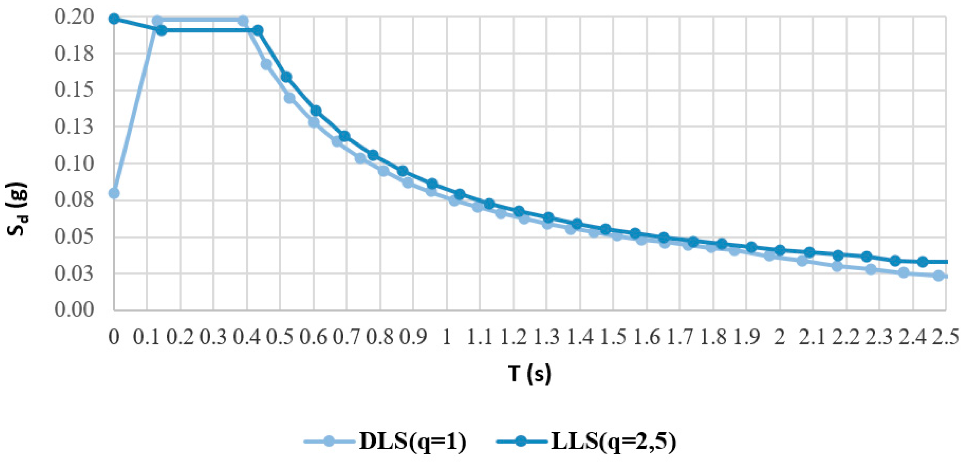
31]. Seismic action is modelled across the design spectrum, which is defined site by site as the return period of the earthquake changes according to Italian Building Code [
30,
31]. Seismic demand can be reduced through the behaviour
structure factor q. The Damage Limitation State (DLS) is considered as q = 1, the structure remains in the elastic field, while for the Life-safety Limit State (LLS), q = 2.5 is assumed, referring to a study conducted by Vona on the Italian building heritage [
25,
32]. The pseudo-acceleration spectral forms in
Figure 3 are obtained.
3.3. Two-Dimensional Preliminary Analysis of Retrofitting System Capabilities
A two-dimensional preliminary analysis evaluates the capabilities of the retrofitting system anchored on the external frame of the existing structure in longitudinal direction.
In the numerical analysis floor slabs are considered rigid in-plane and the structure is considered fixed at the base, neglecting interactions with the ground. We consider the translational masses, which take into account the translational inertia of the structure.
Translational masses are defined from the weights associated for each level. Considering the infinitely rigid plane and having the columns of equal stiffness, the part share of the plane mass, associated with the external frame in longitudinal direction, is calculated by dividing the mass associated with each plane by three (see
Table 2).
In order to evaluate the effectiveness of the application of a bracing lattice to the original structure, modal parameters and DLS shear forces are compared. An initial comparison does not take into account the shear forces at the LLS, since the response spectra to DLS and LLS have almost the same values for the periods of interest (see
Figure 3 and
Table 3). The modal parameters of the original frame in the absence of the retrofitting system are reported in
Table 3, and the floor shear forces with response spectrum are collected in
Table 4.
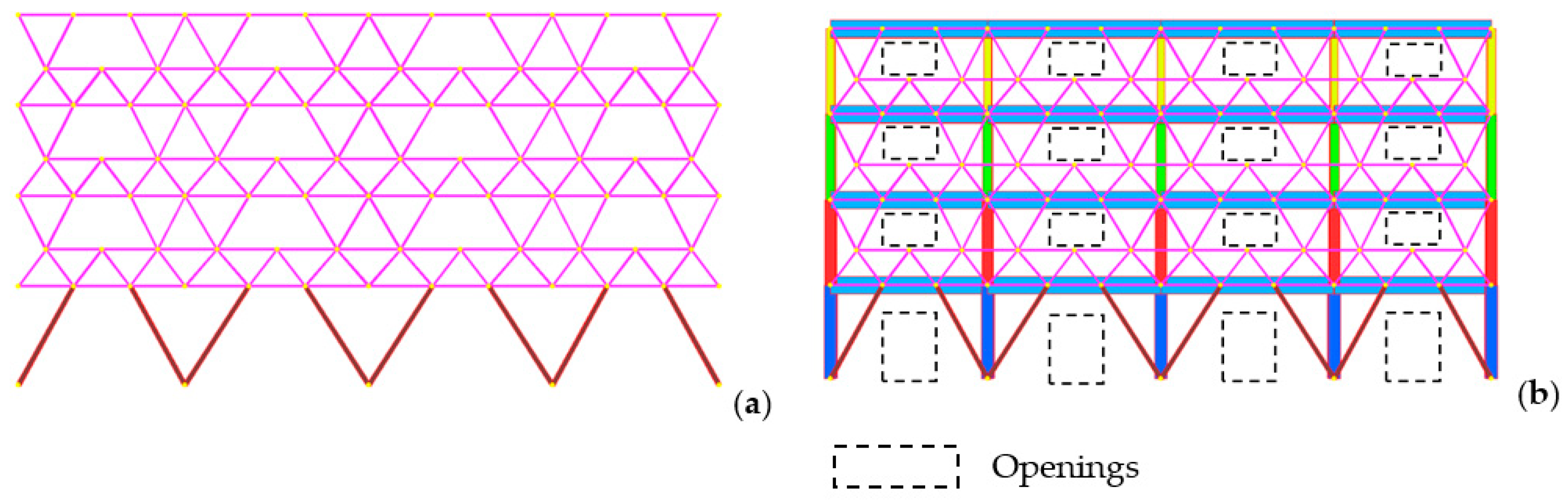
The lattice bracing system shown in
Figure 4a is then applied to the external frame in the plane of the frame (
Figure 4b), neglecting in a first approximation the presence of openings on the façade.
A number of different configurations of the lattice bracing system is considered by varying the size and the numbers of the culms per rod and evaluating later the effectiveness of using engineered bamboo.
The following configurations are analysed with each rod consisting of:
1 IRI culm (75 mm external diameter and 8 mm thickness);
2 IRI culms (75 mm external diameter and 8 mm thickness);
1 IRI culm (90 mm external diameter and 9 mm thickness);
2 IRI culms (90 mm external diameter and 9 mm thickness);
3 IRI culms (90 mm external diameter and 9 mm thickness).
Modal analysis and response spectrum analysis are repeated for each configuration. The results are compared in terms of modal parameters and floor shear forces in relation to the structure without retrofit. In particular,
Table 5 reports the reduction of the periods as a percentage. Note that as the cross-sectional area of the culms and the number of culms per rod increase, the period is reduced as the structure becomes stiffer. This highlights that the insertion of the lattice increases the stiffness of the frame, thus reducing plane movements.
Additionally, the floor shear forces are reduced increasing the number and the cross sections of the rods as shown in
Table 6. In particular, the results show that the bracing system is able to relieve the column on the upper floors where the original structure has columns with a smaller cross, while in the first inter-storey, the shear forces reduction is very small.
Since the reduction at the first level is not significative, in the first inter-storey the bamboo culms are substituted by engineered bamboo rods with a cross section of 15 cm x 15 cm, leaving bamboo culms in the other floors; reference is made also to a lattice structure completely made of engineered bamboo. Engineered bamboo refers to scriber bamboo, whose mechanical performance is defined in [
33]. The percentage reduction of floor shear forces in these configurations are reported in the last columns of
Table 6.
As it can be seen in
Table 6, for the two configurations that involve the engineered bamboo on floor 1 and, respectively, a culm and two culms on the upper ones, there is an excessive stiffening of floor 1 compared to the other floors that can hinder the formation of a global collapse mechanism. The combination of engineered bamboo at the first inter-storey and three bamboo culms at the higher level has almost the same performance of a fully engineered bamboo grid. Taking into account the greater sustainability of bamboo in its natural form, the optimal configuration is defined as the system that presents engineered bamboo on the first floor and three bamboo culms per rod on the upper floors.
Starting from this configuration, the possible presence of openings is taken into account. In particular the openings shown in
Figure 5b are considered.
The grid is modified accordingly, and in this new configuration, the reduction of the floor shear forces on inter-storey 1 is much lower than in previous cases (
Table 7).
As reported in
Table 7, it is necessary to replace the engineered bamboo on inter-storey 1 with steel profiles (hollow normalized profile with circular section, external diameter 101.6 mm and thickness 10 mm) to obtain a significative reduction of floor shear forces, in fact the reduction goes from 20% to 48% employing steel instead of engineered bamboo.
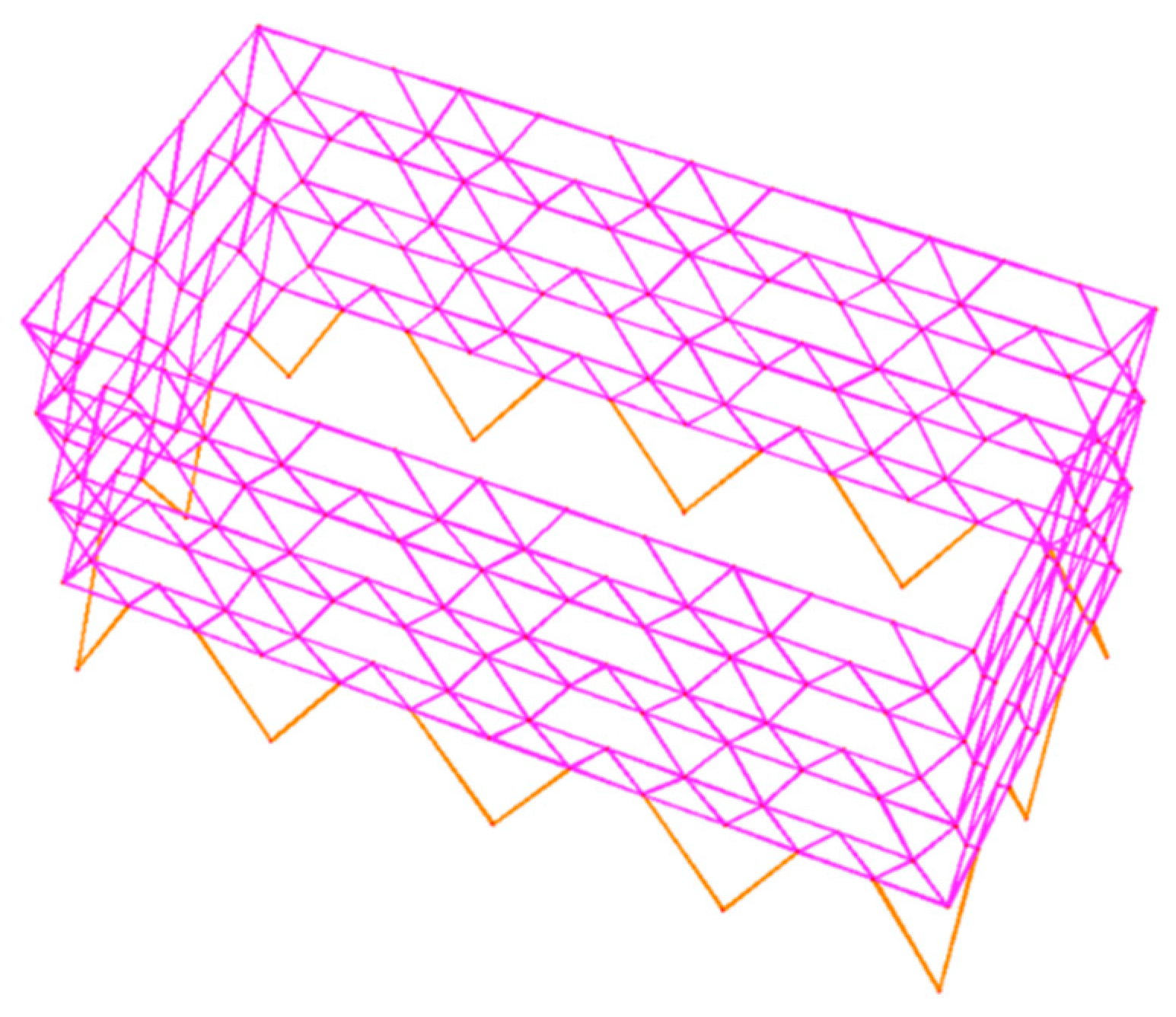
3.4. Spatial Structural Behavior Analysis: Hybrid Steel-Bamboo Lattice System
In order to analyse the spatial behaviour of the structure, the retrofitting system with hybrid steel–bamboo lattice system model is considered in a three-dimensional context (
Figure 6).
In a three-dimensional model, in addition to the translational masses, the rotational masses (connected to rotational inertia) are considered. Translational masses are defined in the longitudinal and transversal directions and rotational masses around vertical axis. The rotational inertia of the masses, with respect to the centre of gravity, is defined as follows:
where
Mi represents the mass of i-floor, a and b represent the size of the floor in the plane.
The weights, the translational masses and the rotational masses of each inter-storey are collected in
Table 8.
The primitive structure is analysed with the elastic modulus E corresponding to a characteristic compression resistance of 30 MPa and with a halved elastic modulus to take into account the mechanical performance of existing damaged buildings. The results differ by a few percentage points, and for brevity, only the results for the structure with the reduced E are reported. The modal parameters related to the structure without retrofit and with retrofit are compared, confirming a significative reduction in the period of vibration (
Table 9).
The shear forces corresponding to DLS and LLS in longitudinal direction (that are greater than the transversal direction) are reported in
Figure 7. In dark blue are indicated the stresses related to the RC frame, given by the sum of the shear forces on each column of the same plane, in the considered direction; in light blue the plane shear forces on the structure without retrofit are indicated. The efficiency of the proposed system is confirmed, and significant reductions in shear forces are obtained in both DLS and LLS cases (
Figure 7 and
Table 10).
The reduction of the period implies an increase in the spectral acceleration but, as can be seen in
Figure 3, the increase related to this reduction is low compared to the whole forces insisting on the structure.
Furthermore, the retrofitting system absorbs a significant part of the seismic forces, allowing a significant reduction of the stresses on the original structure, as shown by the difference between the shear forces in the structure with and without retrofitting (
Figure 7).
The floor displacements and the inter-floor displacements for DLS state with and without retrofit are reported in
Figure 8 and
Table 11. A significant reduction is obtained in the case of a structure with the retrofit system here designed.
The rods of the bracing system are verified at compression or tension and at instabilities in compliance with ISO standards.
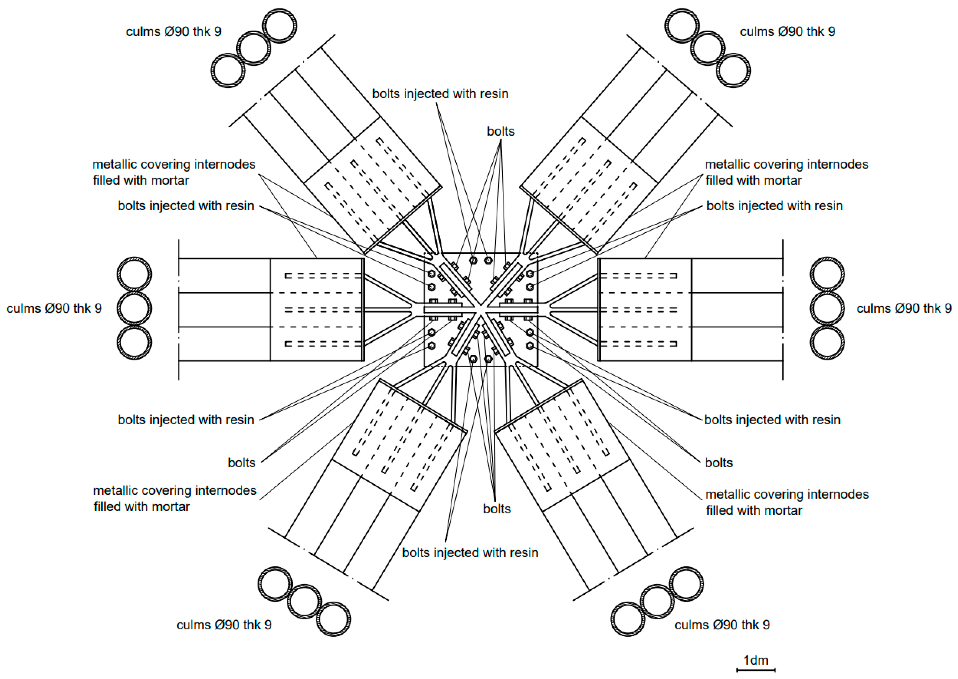
3.5. Hypothesis of Anchoring Original Structure-Retrofitting System
A possible anchorage of the lattice structure to the original frame is presented in
Figure 9. The connection is made with metal plates at the nodes of the primary structure. The plates are connected to the structure through bolts. The rods conferring in the nodes are made in solidarity with the plates by bolting on vertical metal plates, which in turn are welded to the plate connected to the building. The connection with the culms, may have different choices. A possible reference could be the connections used in the German–Chinese house on the occasion of Expo 2010 in Shanghai [
34]. Therefore, metal connectors are provided and inserted inside the culms filled with mortar.
4. Conclusions
The study shows the feasibility of the use of bamboo for structural retrofitting of concrete buildings. In particular, an innovative retrofitting system consisting of hybrid steel–bamboo bracing lattices is proposed. The study of this system demonstrates a good effectiveness in terms of reducing both plane displacements and plane drifts and shear forces on the original structure, thanks to the ability of the lattices to take a significant portion of stresses. The reduction reached in terms of shear force at the base, was 46% in longitudinal direction for DLS and 47% for LLS. The percentage is similar to that of innovative retrofitting techniques like that of steel lattice braces reported in [
9], with the advantages of using sustainable material.
The use of bamboo, like natural materials in general, can raise durability issues which are not fully exploited so far [
35]. The proposed bamboo exoskeleton, however, could allow maintenance and substitution of single bar or grid members.
This research represents a first step and opens the perspective of the use of natural sustainable materials like bamboo in structural retrofitting systems.
Similarly, to the concrete seismic coats that have the dual function of energy insulation and seismic improvement, the system here proposed can be inserted in a package with a thermal insulation function in order to also reduce the transmittance values of the envelope and be part of a context of integrated sustainable, structural and energy improvement.
The results of the presented work may provide useful preliminary insights. The study has been conducted for a site like Bologna where the PGA expected is relatively small (0.2 g), assuming that the retrofitting structure has a ductility compatible with the behaviour factor q = 2.5 [Masi, Vona]. To quantify the effective excursion capacity in the plastic field of the designed system and of the whole structure, it is necessary to employ a non-linear analysis that can be made with a pushover analysis able to describe the origin and evolution of the plastic mechanisms within the structural system.


