Article

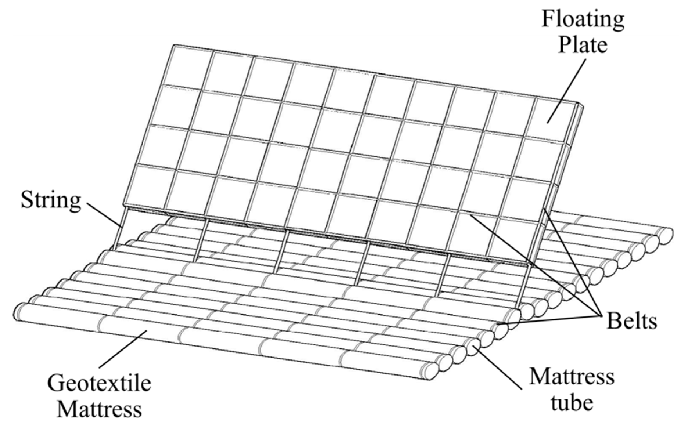
Scour Protection Effects of a Geotextile Mattress with Floating Plate on a Pipeline

1
College of Civil Engineering, Tongji University, Shanghai 200092, China
2
Department of Ocean and Mechanical Engineering, Florida Atlantic University, Boca Raton, FL 33431, USA
*
Author to whom correspondence should be addressed.
Sustainability 2020, 12(8), 3482; https://doi.org/10.3390/su12083482
Submission received: 13 March 2020 / Revised: 18 April 2020 / Accepted: 21 April 2020 / Published: 24 April 2020
(This article belongs to the Section Sustainable Engineering and Science)

Abstract

:
Underwater pipelines are vital to the oil industry. Extending the service life of these pipelines is a key issue in improving the sustainability of oil transportation. A geotextile mattress with floating plate (GMFP) is a novel and sustainable countermeasure for scour and erosion control and is herein introduced to protect a partially buried pipeline from local scour in steady currents. A series of experiments was designed to verify the protection capabilities of the GMFP and investigate its parametric effects on protection. The average seepage hydraulic gradient under the pipeline was adopted to depict the protection effects of the GMFP, and was calculated with the pore pressure readings under the pipeline. The test results show that the GMFP is capable of protecting a pipeline from the onset of local scour in a unidirectional current. The average seepage hydraulic gradient below the pipeline decreases remarkably after a GMFP is installed. The average hydraulic gradient shows a descending trend with increased sloping angle α when 0.64 < sinα < 0.77. The hydraulic gradient hits a nadir at sinα = 0.77 and climbs with the increasing sloping angle when sinα > 0.82. The hydraulic gradient ascends when the bottom opening ratio δ increases from 0.167 to 0.231, due to the decreased intensity of the bottom vortex. The hydraulic gradient drops with a rising plate height, except for a fluctuation at Hp = 0.12 m. An approximate negative correlation is found between the obstruction height of the floating plate and the average hydraulic gradient under the pipeline. This could be partially attributed to the extension and amplification of the bottom vortex on the leeside of the pipeline due to the increased plate obstruction height.

1. Introduction

Underwater pipelines are vital to the oil industry. Oil and gas can be transported safely and sustainably between offshore platforms and oil refineries. After a pipeline is laid on the seabed, hydrodynamic forces like waves and currents interact with the pipeline, and pressure difference appears on two sides of the pipeline. When the pressure difference becomes excessive, local scour may appear and develop underneath the pipeline [1]. As a scour hole develops along the pipeline, the pipeline spans the scour hole. The spanning pipeline can vibrate due to the near bottom flow and can eventually cause pipeline damage and failure. Oil or gas leakage involving pipeline failures can trigger serious environmental and ecological disasters. Over the last few decades, considerable progress has been made on the scour around underwater pipelines.
Investigations have focused on different phases of the scour process beneath the pipelines, including the onset of scour [1,2,3], the equilibrium scour depth [4,5,6], the mechanism of the three-dimensional scour [7,8], the scour rate on the spanwise direction [9,10], and the time scale of scour hole development [11,12,13].
Extending the service life of the pipelines is of significant importance in improving the sustainability of oil transportation. Properly designed protection of underwater pipelines improves the safety, sustainability, and economics of pipeline operation. Protective countermeasures against scour under pipelines have become the focus of many studies. At present, such methods can be generally divided into two categories per their basic functionalities: (1) Stopping the onset of scour and (2) stimulating the self-burial of pipelines. The former aims at preventing the onset of scour by reducing the seepage hydraulic gradient across the pipeline with underwater structures. Such techniques include ripraps [14,15,16], flexible mattresses covering the pipeline [17,18,19], fiber reinforced mats [20], and impermeable plates placed between the pipeline and the seabed [1,21]. In the latter category of protection methods, attempts were made to accelerate scour hole development beneath the pipeline by modifying the cross-section profile of the pipeline. The pipeline could then complete the self-burial process soon after deployment and thus get protected under the seabed. Such methods mainly include spoilers [22,23,24] and flexible plates installed under the pipeline [25].
Traditional ripraps are widely adopted in scour protection in the deployment of previous underwater pipelines. However, this technique is less sustainable or environment friendly compared with novel protection methods. Ripraps covering pipelines require a large amount of rock, and stone mining can cause substantial environmental problems. Recently, a lack of rocks with suitable size and properties has been reported, along with rising costs in rock quarrying and transportation [26]. In addition, potential secondary scour may occur near the edge of the ripraps covering the pipeline [27,28], threating the stability of both the riprap and the pipeline. Thus, traditional riprap protection is unsustainable in both construction and maintenance. Similar drawbacks also exist in some other aforementioned protection techniques.
In this paper, a Geotextile Mattress with Floating Plate (GMFP) is introduced for pipeline scour protection (Figure 1). A GMFP is a novel device designed for scour and erosion protection proposed by [29]. It is composed of a geotextile mattress and a floating plate. The geotextile mattress consists of a string of mattress tubes filled with sand, gravel, cement, or concrete, offering a sound foundation for the GMFP structure. The floating plate is an inflatable plate filled with air or other light materials like polymer foam. It is attached to the geotextile mattress with a series of strings on the bottom edge. In still water, the floating plate rises straight up due to buoyancy. In a unidirectional current, the floating plate leans to the leeside due to the drag force. Thus, it is also known as a “sloping plate”. The strings introduce a gap between the bottom of the floating plate and the mattress, which can serve as a passage for the bed load and the near bottom flow. Belts are added to the mattress and the plate to improve the integral stability of the structure.
Figure 2 demonstrates the basic working mechanism of the GMFP in steady currents. When the floating plate is deployed in a steady current, the approaching flow is separated into two branches. The upper one is diverted to the top of the floating plate. The lower branch flows through the gap between the floating plate and the mattress, reaching the leeside of the plate. The interaction of these two flow branches on the downstream side of the floating plate forms two main vortex systems: The top vortices near the top edge of the floating plate and the bottom vortex close to the bed. The bottom vortex and the resulting low velocity zone create a long safe area on the leeside of the GMFP. The bed load passes the gap between the floating plate and the mattress with the bottom flow, and is deposited in the safe area where the bottom velocity is low. When a GMFP is deployed so that the structure or bed to be protected is located within the safe area, the flow velocity around them is reduced. The sediment deposited near the structure in the safe area also reduces the scour potential. Thus, scour is less likely to occur adjacent to the structure or bed. In wave or oscillating flow conditions, the bottom flow is bidirectional, and GMFPs are thus deployed on both sides of the structure to be protected so that the structure is always located in the safe area of one of the GMFPs (Figure 3).
The GMFP shows sustainability in both deployment and maintenance phases. On one hand, various materials can be used to fill the mattress tubes of the geotextile mattress (Figure 1). Besides the traditional materials mentioned above, local dredging materials like silt and clay can also be used to fill the mattress tubes, which are easily accessible in port and waterway maintenance. Inappropriate disposal of dredged soil can bring pollution to local marine environment. Thus, the deployment of GMFP structures is more sustainable than that of ripraps, which demands large amounts of nonrenewable rocks. On the other hand, the GMFP also shows sustainability in maintenance. After the deployment of the GMFP, dynamic equilibrium is soon reached and maintained in the sediment transportation near the protected seabed. As the GMFP is capable of trapping bed load and depositing the sediment in the safe area on its leeside [26], sand dunes can form near the structure to be protected in normal times. When the sediment transportation capacity of the approaching flow increases dramatically in extreme conditions (i.e., flood and tropical cyclones), the floating plate inclines to the bed, making it easier to survive the disaster. Sand dunes deposited near the protected structure can be scoured, but the structure will still remain intact. After the disaster, the GMFP structure may need some maintenance, but the maintenance does not consume nonrenewable materials like rocks. Sediment trapping can start automatically soon after the hydraulic conditions recovers. The dynamic equilibrium of the seabed sediment transportation in the protected area enables a sustainable protection of the bed and the structure from potential scour.
Studies have been conducted on the GMFP and similar structures. Li and Yu [30] investigated the flow structure on the leeside of a suspended flexible curtain with a simplified Particle Image Velocimetry (PIV) system. An empirical formula was established for the variation of the lee wake vortex dimensions with the curtain height. Xie et al. [26] performed a series of flume experiments on the geotextile mattress with sloping curtain in currents under live bed conditions. Local bed erosion was seized after the structure was deployed. Sediment trapping was detected on both sides of the structure. Xie et al. [31] extended the study of Xie et al. [26] and applied the geotextile mattress with sloping curtain to scour protection under a partially buried pipeline in currents. Visualization test results showed that the structure is capable of slowing down and even reversing the seepage flow beneath the pipeline. Wang et al. [32] investigated the hydrodynamic properties of a sloping curtain. A series of empirical formulae were proposed to estimate the variation of the properties, including the sloping angles, the length of the bottom vortex, and the forces on the structure. Xie et al. [29] improved the flexible protection structure presented by Xie et al. [26], and proposed the GMFP. The seepage stability of the GMFP structure was analyzed in detail based on the experiment results and the potential risk of seepage failure in practical engineering was also discussed.
Both the GMFP studied in this structure and previously proposed structures [26,30,31,32,33] are different novel scour control measures, and are appropriate for different situations. Compared with some of these structures, the GMFP requires less effort and cost in deployment and maintenance [29]. It should be noted that the GMFP is different from the geotextile mattress with sloping curtain studied in Xie et al. [26,31]. Such differences include the structure of the sand-pass openings, and the flexibility of the floating plate (curtain), to name a few. Structural distinctions in these two devices can result in a different flow pattern downstream and cause further variation in protection of underwater structures. Previous achievements are not necessarily applicable to the GMFP. Thus, it is necessary to validate the protection effects of the GMFP and investigate the influence on the protection.
As mentioned above, the dominant cause of the onset of scour below the pipelines is the excessive seepage hydraulic gradient in the soil. If a pipeline is located in the safe area on the leeside of the GMFP, the approaching flow velocity could be remarkably reduced. Thus, the seepage hydraulic gradient under the pipeline can be decreased and the onset of scour is less likely to occur.
In this research, the GMFP was introduced as a protective measure against scour under the pipelines in steady currents (Figure 2). Pore pressure beneath the pipeline was measured to calculate the seepage hydraulic gradient. A series of tests were designed to investigate the protective effects of the GMFP on a partially buried pipeline. The protective effects of the GMFP were verified and the effects of the GMFP design parameters were evaluated. The results of this study are helpful to improve the understanding of the scour protection effects of the GMFP and accelerate the practical application of the GMFP, which can improve the sustainability of pipeline operation.

2. Experiment Setup

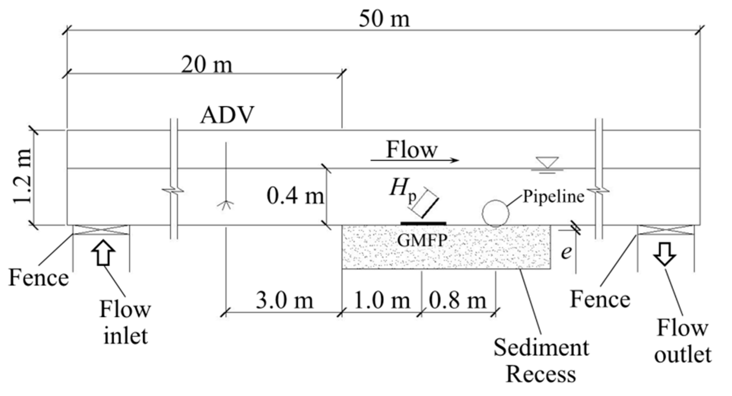
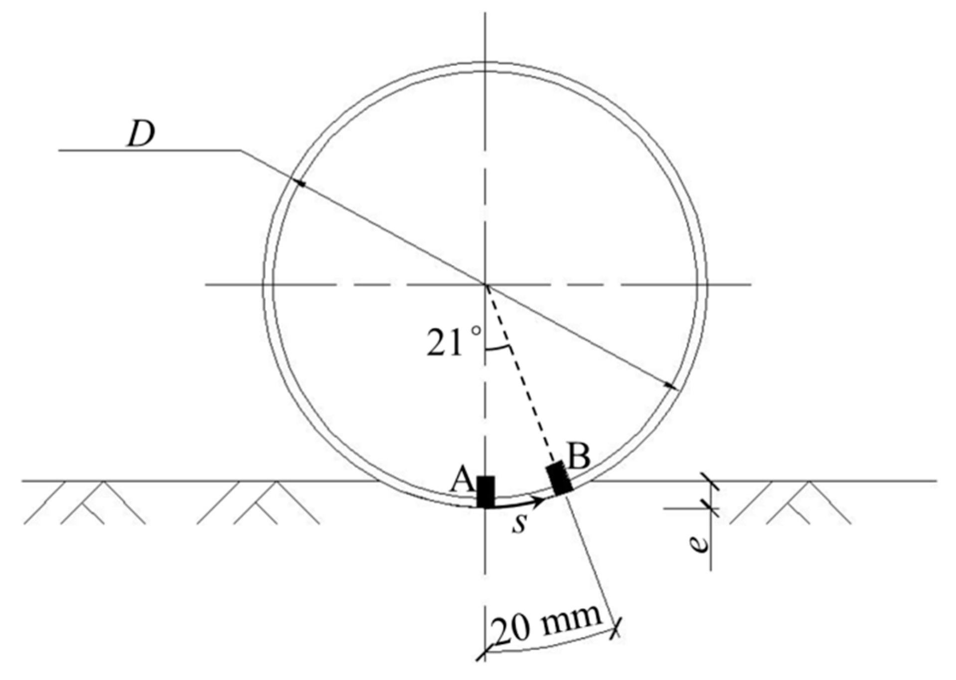
2.1. Experimental Apparatus

The experiments were conducted in the Laboratory of Hydraulic and Harbor Engineering at Tongji University. Figure 4 shows the side view of the flume and the experimental setup. The glass-sided flume is 50 m long, 0.8 m wide and 1.2 m deep. Two metal fences are installed at the flume inlet and outlet to stabilize the current in the flume. The flow in the flume is generated by a pumping system, which is capable of producing a steady current at 1.0 m/s with 0.4 m flow depth. A sediment recess with a length of 2.7 m and a depth of 1.0 m is located 20 m downstream of the entrance of the flume. The bottom of the flume and the recess, and all side walls of the recess are made of impermeable concrete. Uniform sand with a median grain size d50 = 0.16 mm and geometric standard deviation σg = (d84/d16)1/2 = 1.4 was used in this research. The sediment was selected based on previous studies on scour under pipelines.
A plastic pipeline which was 0.8 m long and 0.11 m in diameter was chosen as the model pipeline. The pipeline was partially buried with the embedment depth e = 0.5 cm (Figure 4). Both ends of the pipeline were fixed to avoid pipeline movement during the experiments. A series of GMFP models were used in the experiment (Figure 5). The width of the GMFP models was 0.8 m, the same as the flume width. The height of the floating plate Hp varied from 0.08 m to 0.16 m. The length of the GMFP mattress was 0.25 m. The GMFP model was placed at 1.0 m to the upstream end of the sediment recess. The distance between the GMFP and the pipeline was 0.8 m, which was selected according to the results of Xie et al. [26] to achieve the optimum protection effects. An Acoustic Doppler Velocimeter (ADV) was placed 3.0 m upstream to the sediment recess to monitor the averaged approach velocity.
Two digital pore pressure transducers (Chengdu Test Electronic Information, Chengdu, China) were used in this study. The full range of the pressure sensors is 10 kPa, which is capable of capturing the variations in the pressure difference on two sides of the pipeline. The sampling rate of the pressure sensors was 100 Hz. The onset of scour was reported to start on the downstream side of the pipeline [2,34] and numerical simulations on the seepage field under the pipeline showed that the upward seepage hydraulic gradient reaches the maximum value at the intersection of the pipeline surface and the downstream bed [3,35]. Thus, the seepage hydraulic gradient on the downstream side under the pipeline was the focus of this study. The average seepage hydraulic gradient was calculated based on the pressure sensor readings (Figure 6). Sensor A was installed at the bottom of the pipeline on the vertical axis and Sensor B was installed close to the bed surface. The arc length between Sensors A and B was 20 mm. Thus the averaged seepage hydraulic gradient between points A and B ∂(p/γ)/∂s was calculated by (Figure 6):
s ( p γ ) = p A p B γ A B ,
where γ is the specific weight of water; s is the distance along the perimeter of the pipeline; pA and pB are pore pressure at Sensors A and B, respectively, and A B is the arc length between Sensors A and B, which is 20 mm. This equation is derived from the definition in Sumer et al. [2].
The pressure measurements were started before the current was generated and lasted until at least 3 min after the flow velocity became stable when no scour occurred. Thus, the variations in the readings were completely recorded. The total duration of a test case was about 8 to 10 min for the cases where scour did not occur. For the cases where scour did occur, readings were recorded until the scour hole extended to the full length of the pipeline.

2.2. Experimental Cases

The design parameters of a GMFP include the plate height Hp, the sloping angle α, and the opening ratio δ, which is defined as:
δ = H g H p + H g ,
where Hg is the height of the gap between the floating plate and the geotextile mattress, and Hp is the height of the floating plate (Figure 2). In this study, a total of 15 cases were designed for the experiment. The flow depth was set at h0 = 0.4 m in all cases. The average velocity was constant at 0.4 m/s. The cases were divided into four groups. Group A was set as a control group; no GMFP was installed and the pipeline was unprotected. Groups B, C, and D, respectively, focused on the effects of the sloping angle α, the opening ratio δ, and the plate height Hp, respectively. In each group, only one parameter was changed while the others were kept constant. Further details of the cases are listed in Table 1. The aim of the present experiment is to validate the protection capability of the GMFP and reveal the qualitative variation mode of the protective effects with the GMFP design parameters. Thus, the scaling was considered less important. More comprehensive investigations will be presented in future papers with scaling considered and other parameters included.

3. Experiment Results

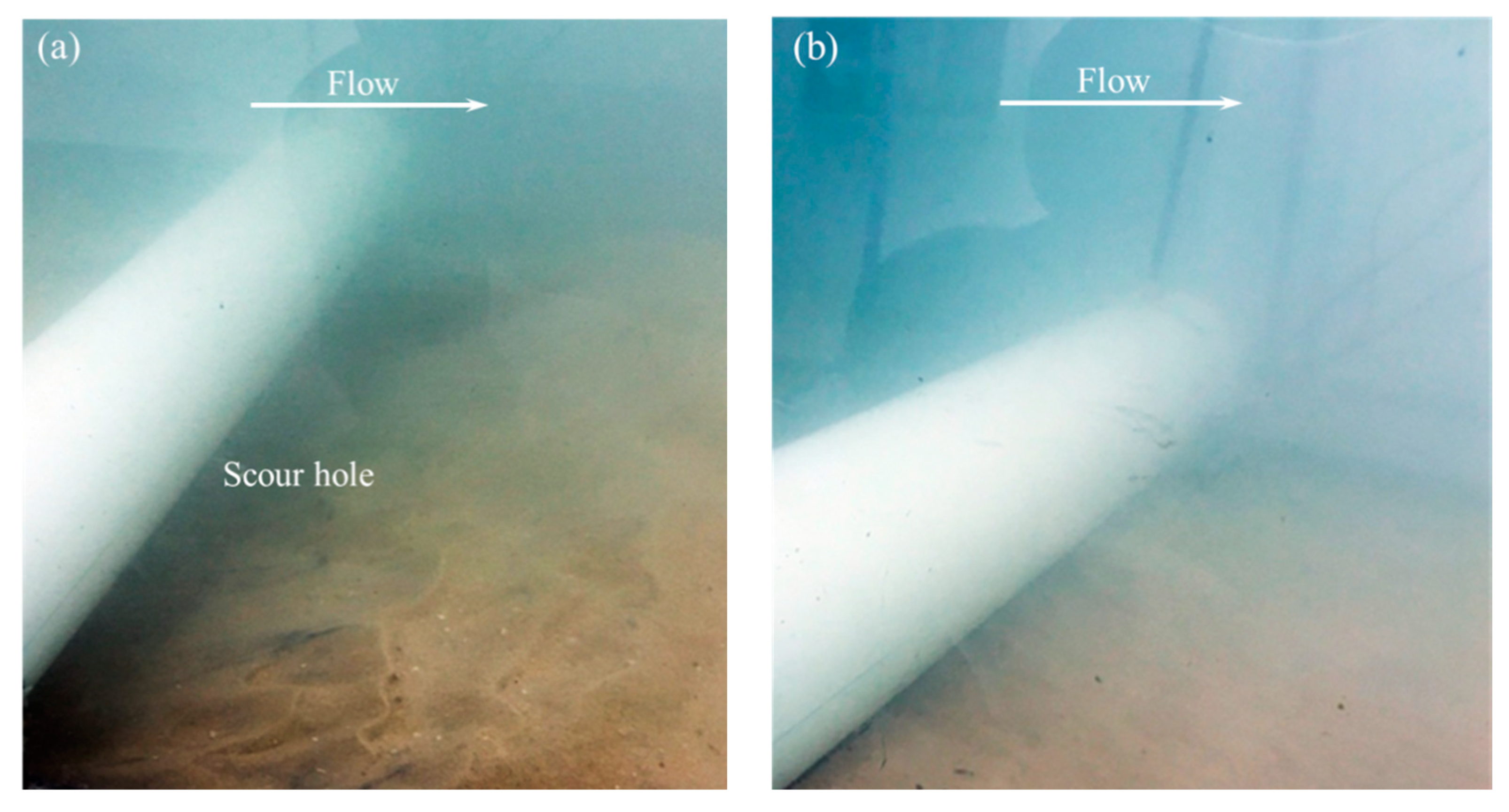
3.1. Verification of GMFP Protection Effects

Two additional, independent test cases were conducted to observe the protective effects of the GMFP. The observation test was based on Case A1, where the GMFP was not installed and the pipeline was unprotected, and Case B4, where a GMFP was deployed upstream to the pipeline. The steady current was maintained at 0.4 m/s for 30 min. The other experimental parameters were all kept unchanged in Table 1. Figure 7 shows the sand bed adjacent to the pipeline without a GMFP (Figure 7a) and with a GMFP (Figure 7b) after the test. This figure shows that after 30 min of flow, the sediment below the pipeline without a GMFP suffered serious scouring, while the bed with a GMFP installed remained almost intact. Therefore, we demonstrate that the GMFP is capable of protecting a pipeline from scour in steady currents.
Table 2 shows the experimental results of Cases A1 (control case) and B4. It shows that while serious scour appeared in Case A1, no scour occurred in Case B4 (Figure 7). The averaged seepage hydraulic gradient across the pipeline was reduced by about 65% after the GMFP is installed (Case B4 compared with Case A1). For all of the tested cases, scour underneath the pipeline was only observed in Case A1, the control case. The GMFP is therefore proven to be capable of decreasing the excessive seepage hydraulic gradient under the pipeline in currents, which is regarded to be a major cause of the onset of scour of pipeline.

3.2. Effects of GMFP Sloping Angle on the Averaged Seepage Hydraulic Gradient (Test Group B)

Figure 8 shows the variation of average seepage hydraulic gradient ∂(p/γ)/∂s with the sloping angle α varying from 35° to 60°. The other two variables were kept constant, i.e., opening ratio δ = 0.231 and plate height Hp = 0.10 m. The sloping angle was normalized as sinα. In general, the average seepage hydraulic gradient decreases with an increase of sloping angle when sinα is between 0.64 and 0.77, after a modest increase when sinα increases from 0.57 to 0.64. The average hydraulic gradient reached the minimum value for the tested range of parameters at sinα = 0.77, and then rose when sinα > 0.82. The nadir point in this curve can be regarded as an optimum sloping angle of the GMFP in the present configuration. The variation of the seepage hydraulic gradient with the sloping angle can be partially attributed to the intensity change and the deformation of the bottom vortex (Figure 2), which will be discussed in detail in a later section.

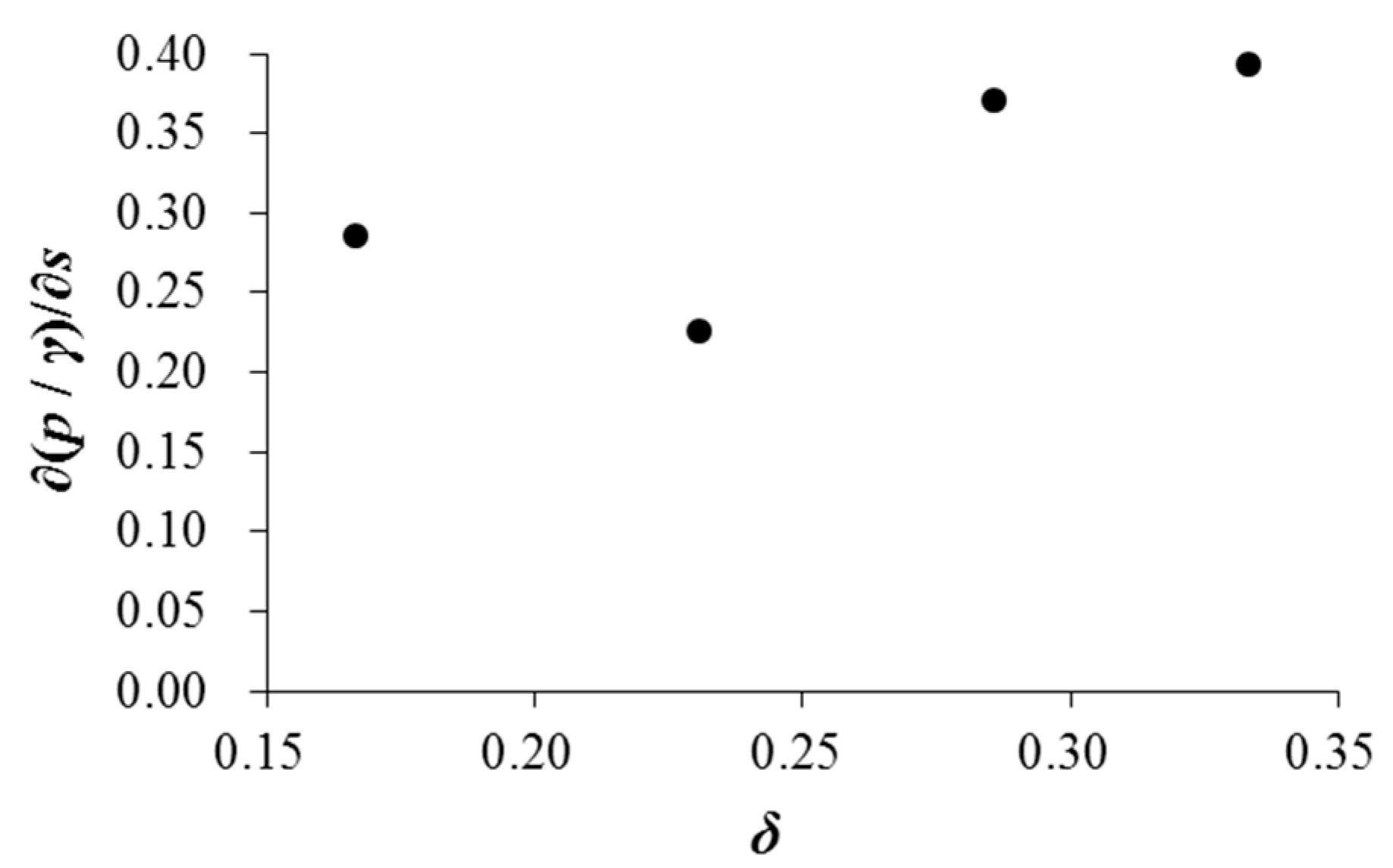
3.3. Effects of GMFP Opening Ratio on the Averaged Seepage Hydraulic Gradient (Test Group C)

Figure 9 shows the variation of the average seepage hydraulic gradient ∂(p/γ)/∂s with the opening ratio δ varying from 0.167 to 0.333. The other two variables were kept constant, i.e., sloping angle α = 50° and plate height Hp = 0.10 m. The average seepage hydraulic gradient drops slightly when the opening ratio δ increases from 0.167 to 0.231, hitting a nadir at δ = 0.231, and then increases with the increase of the opening rate when δ > 0.231. The seepage hydraulic gradient ∂(p/γ)/∂s increases by about 40% when δ increases from 0.231 to 0.333. More detailed analysis on the variation pattern is given in a later section.

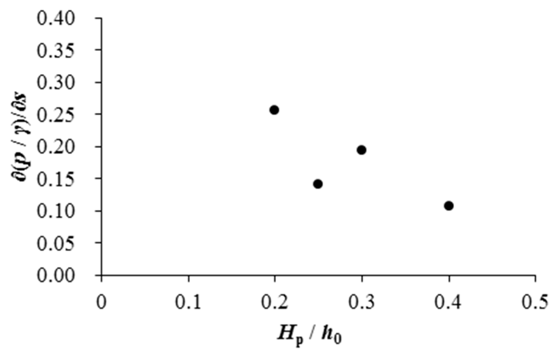
3.4. Effects of GMFP Plate Height on the Averaged Seepage Hydraulic Gradient (Test Group D)

Figure 10 shows the variation of the average seepage hydraulic gradient ∂(p/γ)/∂s with the GMFP plate height Hp varying from 0.08 m to 0.16 m. The other two variables were kept constant, i.e., sloping angle α = 50° and opening ratio δ = 0.231. The plate height was normalized as the relative plate height Hp/h0, where h0 = water depth. In Figure 10, the average seepage hydraulic gradient shows a gradual decrease with increased plate height, except for a fluctuation at Hp/h0 = 0.3 (Hp = 0.12 m). The drop of the seepage hydraulic gradient with increasing plate height may also be associated with the increase of the obstruction height. A more detailed discussion of the relationship between the obstruction height and the average seepage hydraulic gradient will be presented in the next section.

4. Discussion

4.1. Effects of GMFP Obstruction Height on the Hydraulic Gradient

It has been proved that the dimensions of the bottom vortex downstream to a similar structure are a function of the structure blockage [30], and the protective effect is closely associated with the length of the bottom vortex (Figure 2). It is thus necessary to analyze the variation of the seepage hydraulic gradient with the blockage of the plate to further explain the variation of the hydraulic gradient with the sloping angle and the plate height in Figure 8 and Figure 10.
The variation of the averaged seepage hydraulic gradient ∂(p / γ)/∂s with the sloping angle and the plate height is plotted as the relationship between the hydraulic gradient and the obstruction height of the floating plate Hpsinα (Figure 11). The result of the control test is also included, where the obstruction height is zero. The data in Figure 9 is not included, as the tests in Figure 9 focus on the height of the gap, which is independent from the obstruction height. Figure 11 demonstrates that the averaged seepage hydraulic gradient under the pipeline decreases with increasing obstruction height in a nonlinear trend. The descent rate gradually drops with the rise of the obstruction height.
In Figure 11, the results of Xie et al. [31] are also plotted. Xie et al. [31] visualized the protection effects of a similar scour control method called geotextile mattress with sloping curtain in steady currents. The variation of the hydraulic gradient with the obstruction height of the previous study [31] also shows a gradual decrease with the decrease rate slowing down. The minor difference in the variation pattern of the hydraulic gradient in these two studies may be attributed to two factors. The first factor is the structural differences between the device in Xie et al. [31] and the one studied in this study, which could result in differences in local flow patterns and thus protection effects. The variation pattern of the hydraulic gradient with the obstruction height can also be different. Another factor may be that the test conditions in this study are significantly different from the earlier study, including the differences in the experimental setup, and the hydrodynamic conditions.
A possible explanation for the variation of the hydraulic gradient with the obstruction height is hereby presented. With the increase of the obstruction height, the bottom vortex on the leeside of the GMFP (Figure 2) tends to be enhanced. Li and Yu [30] found that the bottom vortex extends downstream with the rise of the obstruction height. With the extension of the bottom vortex, the low velocity zone and the safe area would stretch as well. When the distance between the pipeline and the GMFP is constant, the pipeline gradually approaches the bottom vortex, and moves further into the safe area due to the extension of the bottom vortex and the safe area. The influence on the pipeline intensifies. The near bottom flow velocity drops with the extension of the bottom vortex. As a result, the flow adjacent to the pipeline may slow down and the seepage hydraulic gradient beneath the pipeline can decrease.
Additionally, it should be noted that not all of the data points of this study in Figure 11 collapse on a single curve, indicating that additional mechanisms may also affect the variation of the hydraulic gradient except for the elementary mechanism above. Further investigation is necessary on the interrelationship among the design parameters of the GMFP, the distance between the GMFP and the pipeline, and the flow conditions. Such investigations will be helpful to better understand the interaction mechanism between the pipeline and the GMFP structure in various conditions.

4.2. Effects of the Opening Ratio on the Hydraulic Gradient

In Figure 9, the hydraulic gradient drops slightly with the opening ratio when δ < 0.231. The hydraulic gradient hits a nadir at δ = 0.231, and then increases with the increase of the opening rate when δ > 0.231. This variation can be explained as follows.
When the opening ratio is zero, the gap between the floating plate and the mattress does not exist, and the bottom flow is not capable of passing the plate from the bottom. In this occasion, only one vortex exists on the leeside of the pipeline [30]. When the opening ratio δ increases from 0 to 0.231, the gap appears and widens. The bottom flow appears in the gap (Figure 2), which significantly changes the flow pattern on the leeside of the GMFP. The top vortices appear; the bottom vortex can gradually move downstream and deform, and the intensity of the bottom vortex is slightly reduced [30]. As the bottom vortex moves to the leeside, the impact of the bottom vortex on the pipeline intensifies, despite the drop in the intensity of the bottom vortex. Thus, the hydraulic gradient across the pipeline decreases with the rising opening ratio when the opening ratio is small. The nadir point on this curve indicates an optimum value of the opening ratio, where the protection effect of the GMFP reaches an optimized value under the specified configuration of other parameters. In practical engineering projects, the opening ratio is optimized on the basis of flume experiments.
With a continuous increase of the opening ratio, the variation trend of the flow pattern on the leeside of the GMFP becomes different. The bottom flow through the gap keeps intensifying with the rising gap height. The intensity of the bottom vortex continues to descend [30], probably due to the disturbance of the intensifying bottom flow. The flow velocity in the low velocity zone increases, and the protective effects fade. It is also reported that the bottom vortex coverage of narrows when the opening ratio increases [30]. Thus, the flow around the pipeline tends to strengthen the average seepage hydraulic gradient rises. If the opening ratio continues to rise, the protective effect of the GMFP may even completely vanish as the bottom vortex could be overwhelmed by intense flow through the opening gap.

5. Conclusions

In this study, a series of physical tests was designed and conducted to verify the protective effects of the GMFP on a pipeline in steady currents. The effects of the GMFP design parameters on the averaged seepage hydraulic gradient under the pipeline are also discussed. These achievements can push forward the practical application of the GMFP, which will improve the sustainability of pipeline deployment and operation by extending the service life of the underwater pipelines. The following conclusions can be drawn based on the results above.
  • A GMFP structure installed on the upstream side of the pipeline is capable of protecting the pipeline from scour in steady currents effectively. For all cases performed in this study, scour beneath the pipeline is successfully prevented when a GMFP is installed. The seepage hydraulic gradient in the soil under the pipeline is significantly reduced after a GMFP structure is deployed.
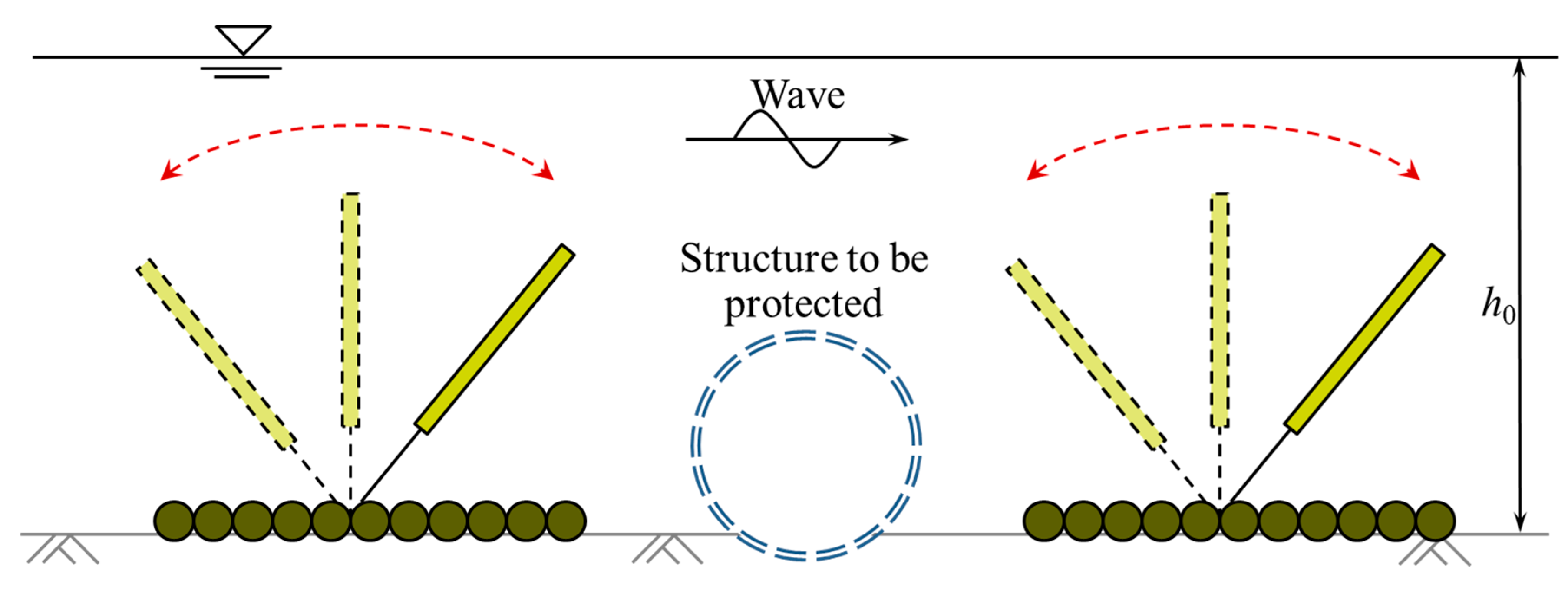
  • The average seepage hydraulic gradient under the pipeline decreases with an increase in the sloping angle α when 0.64 < sinα < 0.77. After hitting a nadir at sinα = 0.77, the hydraulic gradient increases with the sloping angle when sinα > 0.82.
  • The average seepage hydraulic gradient under the pipeline drops with the increase of the opening ratio δ when 0.167 < δ < 0.231, and then increases when δ > 0.231. The rise of hydraulic gradient with the opening ratio can be associated with the drop in the intensity of the bottom vortex.
  • The average seepage hydraulic gradient under the pipeline shows a gradual decrease with increased plate height Hp, except for a fluctuation at Hp = 0.12 m.
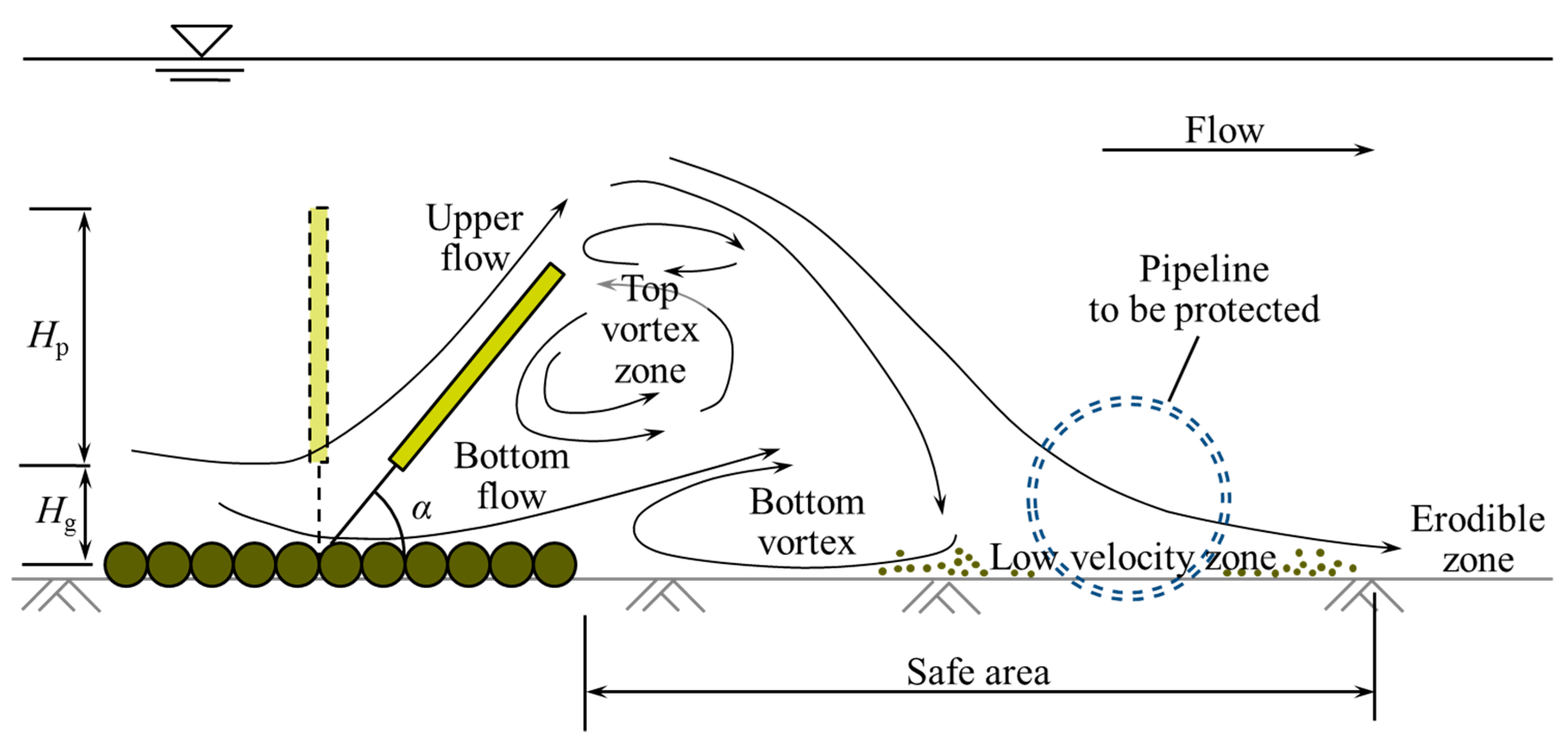
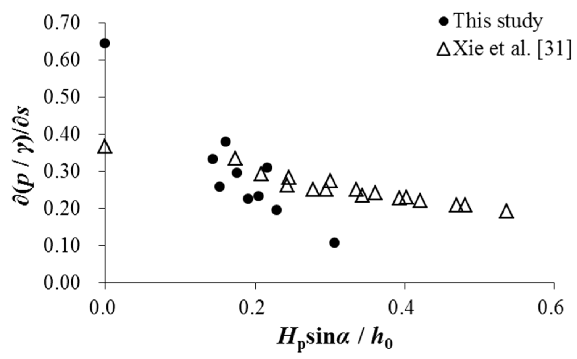
  • The average seepage hydraulic gradient has an approximate negative correlation with the obstruction area of the floating plate (Hpsinα/h0), which can be partially attributed to the extension of the bottom vortex on the leeside of the GMFP with the increase of the obstruction area.

Author Contributions

Conceptualization, Y.Z., L.X., and T.-C.S.; funding acquisition, Y.Z. and L.X.; investigation, Y.Z., L.X., and T.-C.S.; methodology, Y.Z., L.X., and T.-C.S.; resources, Y.Z. and L.X.; supervision, L.X.; visualization, Y.Z. and L.X.; writing—original draft, Y.Z.; writing—review and editing, Y.Z., L.X., and T.-C.S. All authors have read and agreed to the published version of the manuscript.

Funding

This research was funded by the National Natural Science Foundation of China, grant numbers 11172213 and 51479137, and the China Scholarship Council, grant number 201806260166.

Conflicts of Interest

The authors declare no conflict of interest. The funders had no role in the design of the study; in the collection, analyses, or interpretation of data; in the writing of the manuscript, or in the decision to publish the results.

References

  1. Chiew, Y.M. Mechanics of local scour around submarine pipelines. J. Hydraul. Eng. 1990, 116, 515–529. [Google Scholar] [CrossRef]
  2. Sumer, B.M.; Truelsen, C.; Sichmann, T.; Fredsøe, J. Onset of scour below pipelines and self-burial. Coast. Eng. 2001, 42, 313–335. [Google Scholar] [CrossRef]
  3. Gao, F.; Luo, C. Flow-pipe-seepage coupling analysis of spanning initiation of a partially-embedded pipeline. J. Hydrodyn. 2010, 22, 478–487. [Google Scholar] [CrossRef] [Green Version]
  4. Chiew, Y.M. Prediction of maximum scour depth at submarine pipelines. J. Hydraul. Eng. 1991, 117, 452–466. [Google Scholar] [CrossRef]
  5. Haghiabi, A.H. Prediction of river pipeline scour depth using multivariate adaptive regression splines. J. Pipeline Syst. Eng. Pract. 2017, 8, 04016015. [Google Scholar] [CrossRef]
  6. Bui, D.T.; Shirzadi, A.; Amini, A.; Shahabi, H.; Al-Ansari, N.; Hamidi, S.; Singh, S.K.; Pham, B.T.; Ahmad, B.B.; Ghazvinei, P.T. A hybrid intelligence approach to enhance the prediction accuracy of local scour depth at complex bridge piers. Sustainability 2020, 12, 1063. [Google Scholar]
  7. Wu, Y.; Chiew, Y.M. Mechanics of three-dimensional pipeline scour in unidirectional steady current. J. Pipeline Syst. Eng. Pract. 2013, 4, 3–10. [Google Scholar] [CrossRef]
  8. Wu, Y.; Chiew, Y.M. Mechanics of pipeline scour propagation in the spanwise direction. J. Waterw. Port Coast. Ocean Eng. 2014, 141, 04014045. [Google Scholar] [CrossRef]
  9. Wu, Y.; Chiew, Y.M. Three-dimensional scour at submarine pipelines. J. Hydraul. Eng. 2012, 138, 788–795. [Google Scholar] [CrossRef]
  10. Zhu, Y.; Xie, L.; Su, T.C. Visualization tests on scour rates below pipelines in steady currents. J. Hydraul. Eng. 2019, 145, 04019005. [Google Scholar] [CrossRef]
  11. Fredsøe, J.; Sumer, B.M.; Arnskov, M. Time scale for wave/current scour below pipelines. Int. J. Offshore Polar Eng. 1992, 2, 13–17. [Google Scholar]
  12. Zang, Z.; Tang, G.; Cheng, L. Time scale of scour below submarine pipeline under combined waves and currents with oblique incident angle. In ASME 2017, Proceedings of the 36th International Conference on Ocean, Offshore and Arctic Engineering, Trondheim, Norway, 25–30 June 2017; ASME: New York, NY, USA, 2017; V009T10A019. [Google Scholar]
  13. Zhang, Q.; Draper, S.; Cheng, L.; An, H. Time scale of local scour around pipelines in current, waves, and combined waves and current. J. Hydraul. Eng. 2017, 143, 04016093. [Google Scholar] [CrossRef]
  14. Biswas, P.; Barbhuiya, A.K. Countermeasure of river bend scour using a combination of submerged vanes and riprap. Int. J. Sediment Res. 2018, 33, 478–492. [Google Scholar] [CrossRef]
  15. Hong, S.H.; Lee, S.O. Insight of bridge scour during extreme hydrologic events by laboratory model studies. KSCE J. Civ. Eng. 2018, 22, 2871–2879. [Google Scholar] [CrossRef]
  16. Lee, S.O.; Hong, S.H. Turbulence characteristics before and after scour upstream of a scaled-down bridge pier model. Water 2019, 11, 1900. [Google Scholar] [CrossRef] [Green Version]
  17. Crowhurst, A.D. Marine pipeline protection with flexible mattress. Coast. Eng. 1982, 1982, 2403–2417. [Google Scholar]
  18. Gaeta, M.G.; Lamberti, A.; Ricchieri, F.; Zurlo, M. Articulated concrete mattress for submarine pipeline protection: Evaluation of the wave-induced forces and stability analysis. Coast. Struct. 2013, 2, 1116–1125. [Google Scholar]
  19. Huang, W.; Creed, M.; Chen, F.; Liu, H.; Ma, A. Scour around submerged spur dikes with flexible mattress protection. J. Waterw. Port Coast. Ocean Eng. 2018, 144, 04018013. [Google Scholar] [CrossRef]
  20. Yang, C.; Xiao, P.; Zhen, B.; Shen, Z.; Li, L. Effects of vegetation cover on runoff and sediment in field prototype slope by experimental. Adv. Mat. Res. 2012, 518–523, 4707–4711. [Google Scholar] [CrossRef]
  21. Zhang, Z.; Shi, B.; Guo, Y.; Yang, L. Numerical investigation on critical length of impermeable plate below underwater pipeline under steady current. Sci. China Tech. Sci. 2013, 56, 1232–1240. [Google Scholar] [CrossRef]
  22. Chiew, Y.M. Effect of spoilers on scour at submarine pipelines. J. Hydraul. Eng. 1992, 118, 1311–1317. [Google Scholar] [CrossRef]
  23. Oner, A.A. Numerical investigation of flow around a pipeline with a spoiler near a rigid bed. Adv. Mech. Eng. 2016, 8, 1–13. [Google Scholar] [CrossRef] [Green Version]
  24. Zhu, L.; Liu, K.; Fan, H.; Cao, S.; Chen, H.; Wang, J.; Wang, Z. Scour beneath and adjacent to submarine pipelines with spoilers on a cohesive seabed: Case study of Hangzhou Bay, China. J. Waterw. Port Coast. Ocean Eng. 2019, 145, 05018009. [Google Scholar] [CrossRef]
  25. Yang, L.; Shi, B.; Guo, Y.; Zhang, L.; Zhang, J.; Han, Y. Scour protection of submarine pipelines using rubber plates underneath the pipes. Ocean Eng. 2014, 84, 176–182. [Google Scholar] [CrossRef] [Green Version]
  26. Xie, L.; Huang, W.; Yu, Y. Experimental study of sediment trapping by geotextile mattress installed with sloping curtain. Geosynth. Int. 2013, 20, 389–395. [Google Scholar] [CrossRef]
  27. Sumer, B.M.; Fredsoe, J. The Mechanics of Scour in the Marine Environment; World Scientific: Singapore, 2002. [Google Scholar]
  28. Petersen, T.U.; Sumer, B.M.; Bøgelund, J.; Yazici, A.; Fredsøe, J.; Meyer, K.E. Flow and edge scour in current adjacent to stone covers. J. Waterw. Port Coast. Ocean Eng. 2015, 141, 04014044. [Google Scholar] [CrossRef]
  29. Xie, L.; Zhu, Y.; Li, Y.; Su, T.C. Experimental study on bed pressure around geotextile mattress with sloping plate. PLoS ONE 2019, 14, e0211312. [Google Scholar] [CrossRef]
  30. Li, Y.; Yu, G. Experimental investigation on flow characteristics at leeside of suspended flexible curtain for sedimentation enhancement. China Ocean Eng. 2009, 23, 565–576. [Google Scholar]
  31. Xie, L.; Zhu, Y.; Su, T.C. Scour protection of partially embedded pipelines using sloping curtains. J. Hydraul. Eng. 2019, 145, 04019001. [Google Scholar] [CrossRef]
  32. Wang, H.; Si, F.; Lou, G.; Yang, W.; Yu, G. Hydrodynamic characteristics of a suspended curtain for sediment trapping. J. Waterw. Port Coast. Ocean Eng. 2015, 141, 04014030. [Google Scholar] [CrossRef]
  33. Xie, L.; Zhu, Y.; Li, H.; Li, Y.; Yang, Y.; Su, T.C. Local scour near flexible flow deflectors. Water 2020, 12, 153. [Google Scholar] [CrossRef] [Green Version]
  34. Zhu, Y.; Xie, L.; Liang, X. Scour patterns below pipelines and scour hole expansion rate. In Scour and Erosion, Proceedings of the 8th International Conference on Scour and Erosion, Oxford, UK, 12–15 September 2016; Harris, J., Whitehouse, R., Moxon, S., Eds.; CRC Press: Leiden, The Netherlands, 2016; pp. 387–394. [Google Scholar]
  35. Zang, Z.; Cheng, L.; Zhao, M.; Liang, D.; Teng, B. A numerical model for onset of scour below offshore pipelines. Coast. Eng. 2009, 56, 458–466. [Google Scholar] [CrossRef]
Figure 1. Sketch of the Geotextile Mattress with Floating plate (GMFP) [29].
Sustainability 12 03482 g001
Figure 2. Basic working mechanism of the GMFP.
Sustainability 12 03482 g002
Figure 3. Sketch of GMFPs protecting a structure in wave conditions.
Sustainability 12 03482 g003
Figure 4. Experiment setup (side view, not to scale).
Sustainability 12 03482 g004
Figure 5. A GMFP model in the experiment.
Sustainability 12 03482 g005
Figure 6. Pore pressure sensor setup.
Sustainability 12 03482 g006
Figure 7. Sand bed transformation under the pipeline after 30 min flow: (a) Without a GMFP; (b) with a GMFP.
Sustainability 12 03482 g007
Figure 8. Variation of averaged seepage hydraulic gradient with sloping angle.
Sustainability 12 03482 g008
Figure 9. Variation of averaged seepage hydraulic gradient with opening ratio.
Sustainability 12 03482 g009
Figure 10. Variation of averaged seepage hydraulic gradient with relative plate height.
Sustainability 12 03482 g010
Figure 11. Variation of averaged seepage hydraulic gradient with the normalized plate obstruction height.
Sustainability 12 03482 g011
Table 1. Experiment cases.
GroupCaseSloping Angle α (°)Opening Ratio δPlate Height Hp (m)
AA1Control test, without GMFP
BB1350.2310.10
B2400.2310.10
B3450.2310.10
B4500.2310.10
B5550.2310.10
B6600.2310.10
CC1500.1670.10
B4500.2310.10
C3500.2860.10
C4500.3330.10
DD1500.2310.08
D2500.2310.10
D3500.2310.12
D4500.2310.16
Table 2. Experiment results of Cases A1 and B4.
CaseWith GMFPScour Depth (cm)Averaged Seepage Hydraulic Gradient ∂(p/γ)/∂s
A1No6.50.643
B4Yes00.225

