Prevention of Barite Sag in Water-Based Drilling Fluids by A Urea-Based Additive for Drilling Deep Formations


Abstract
1. Introduction
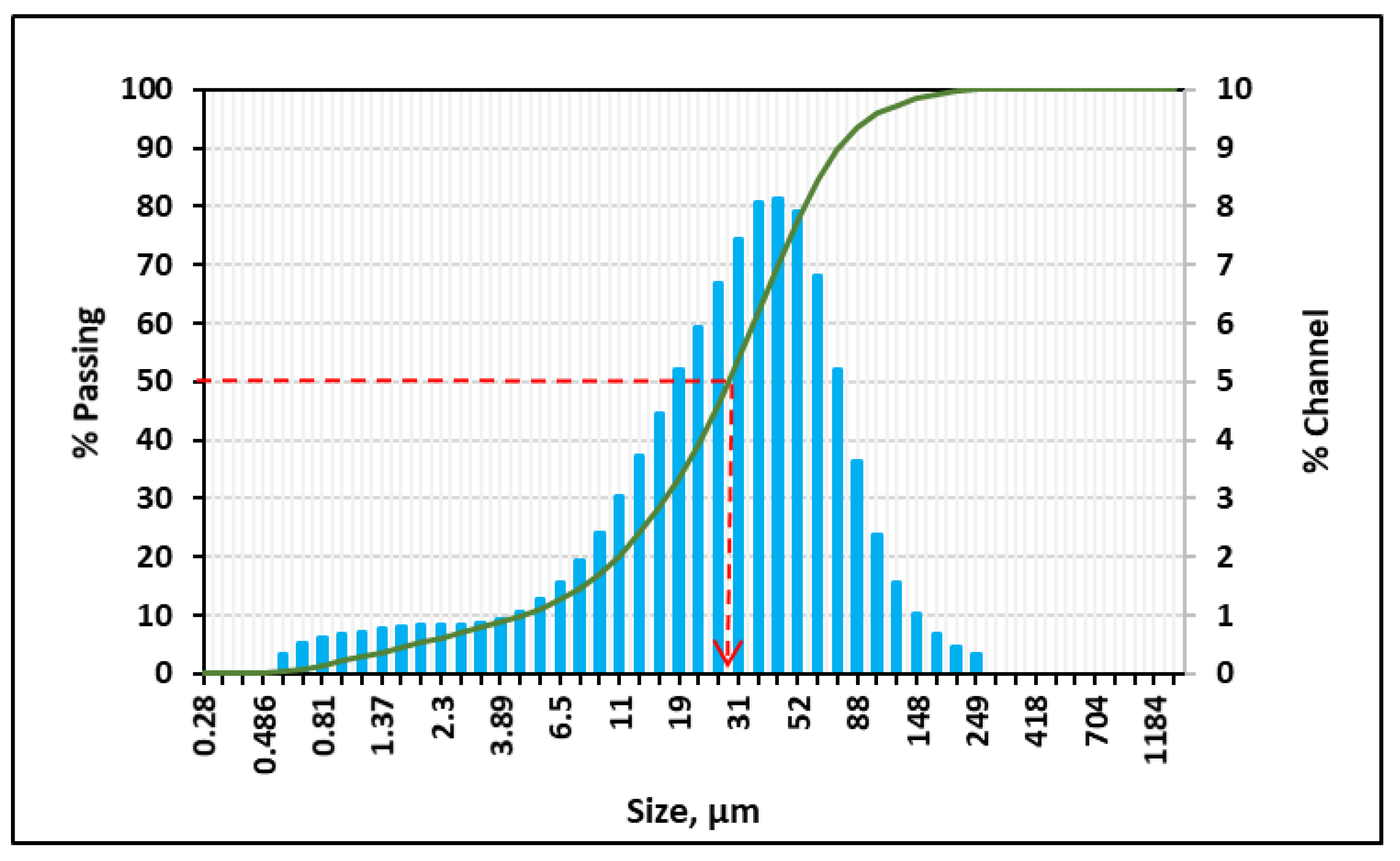
2. Materials
3. Experimental Work
3.1. Fluid Preparation
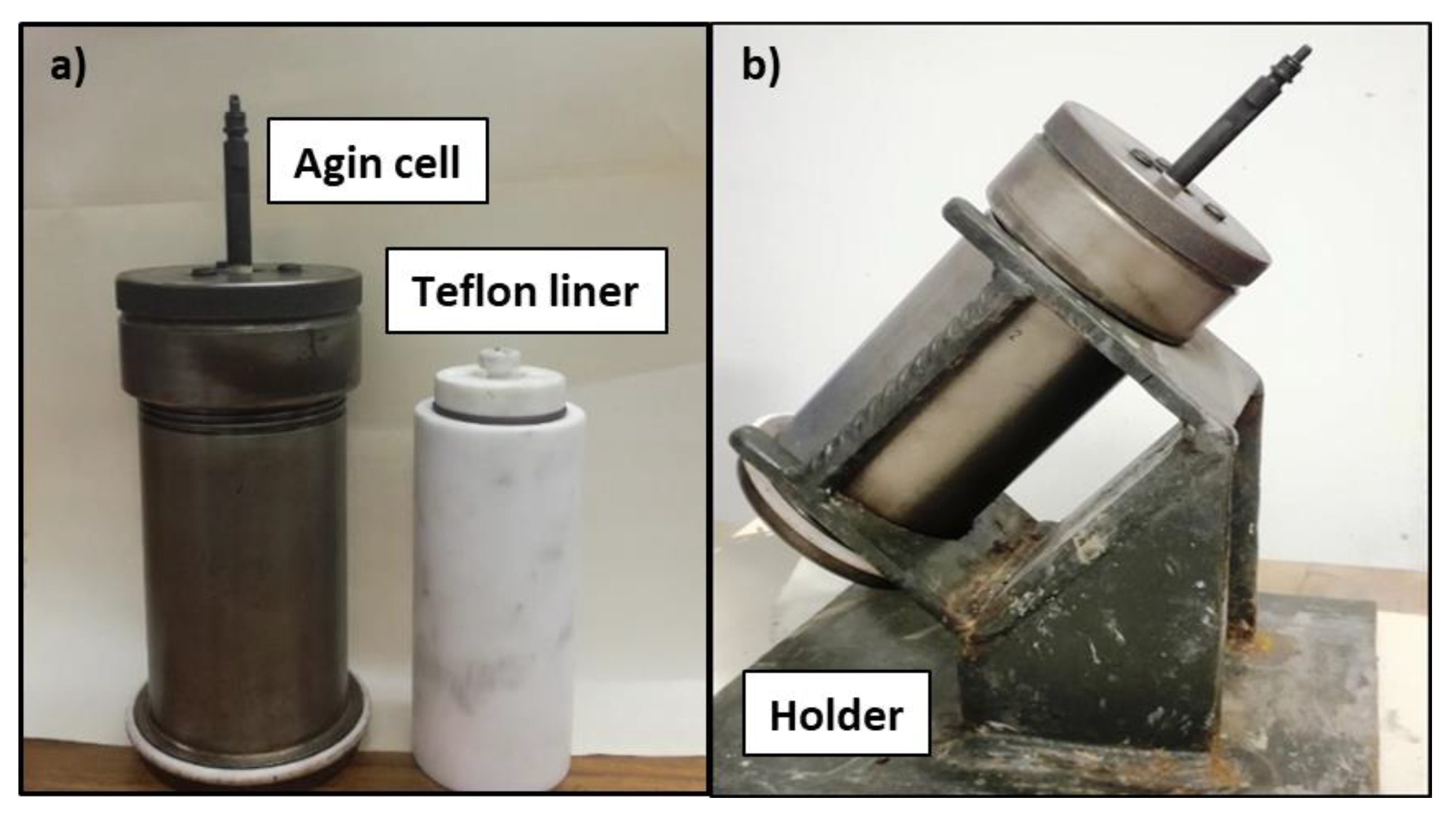
3.2. Sag Tests
3.3. Rheology Measurement
3.4. HPHT Filtration Experiments
4. Results and Discussions
4.1. Sag Tests
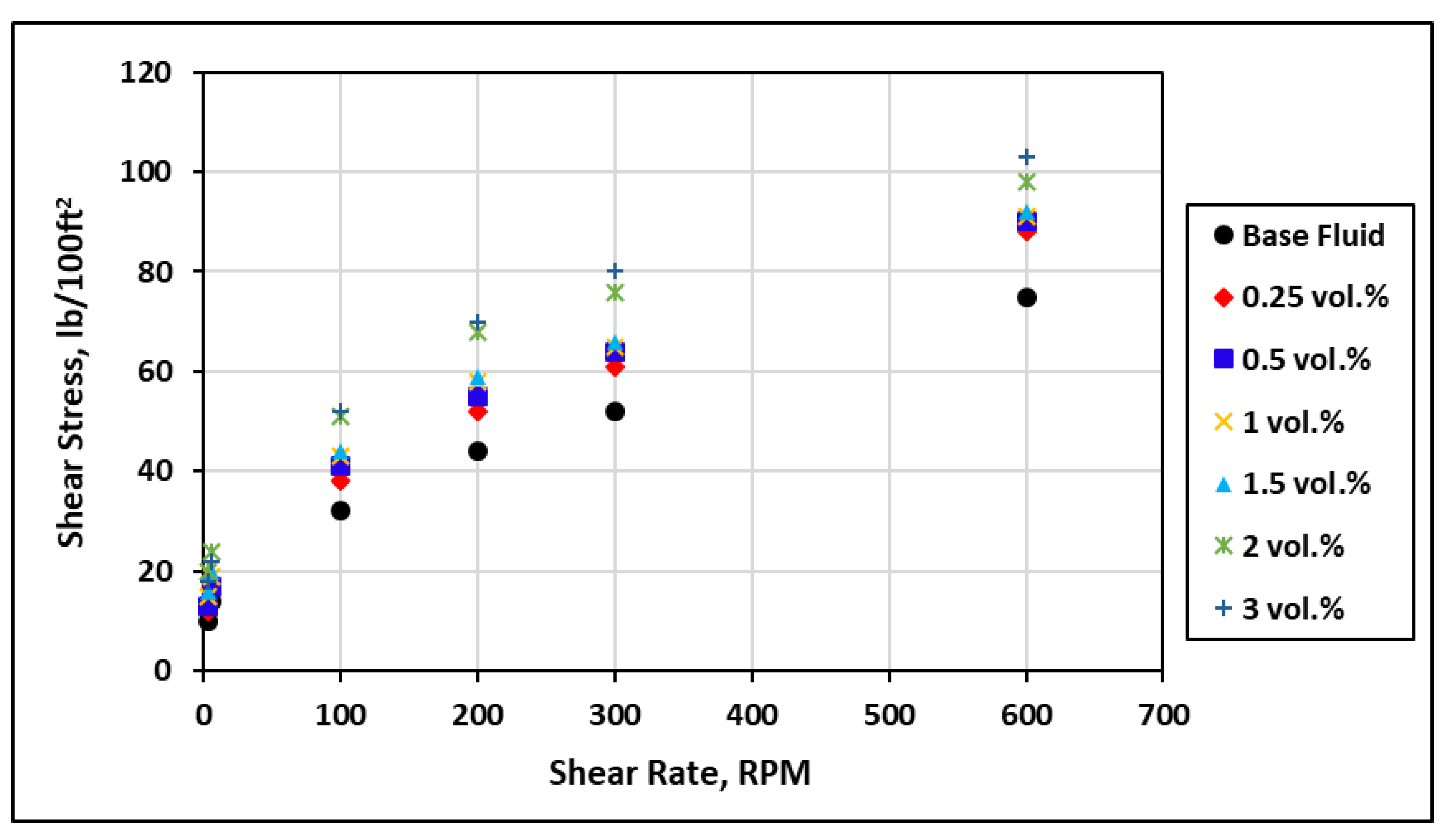
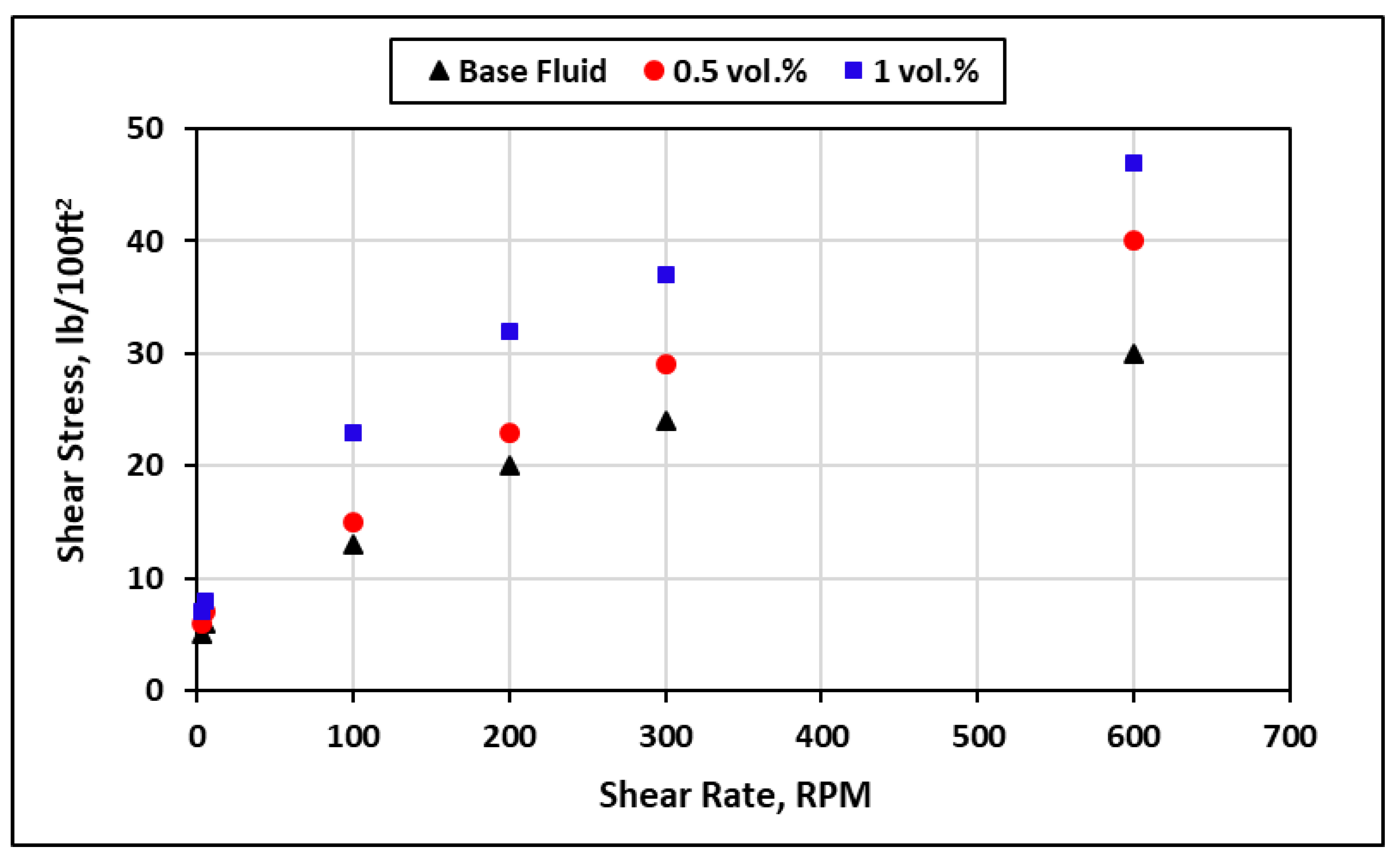
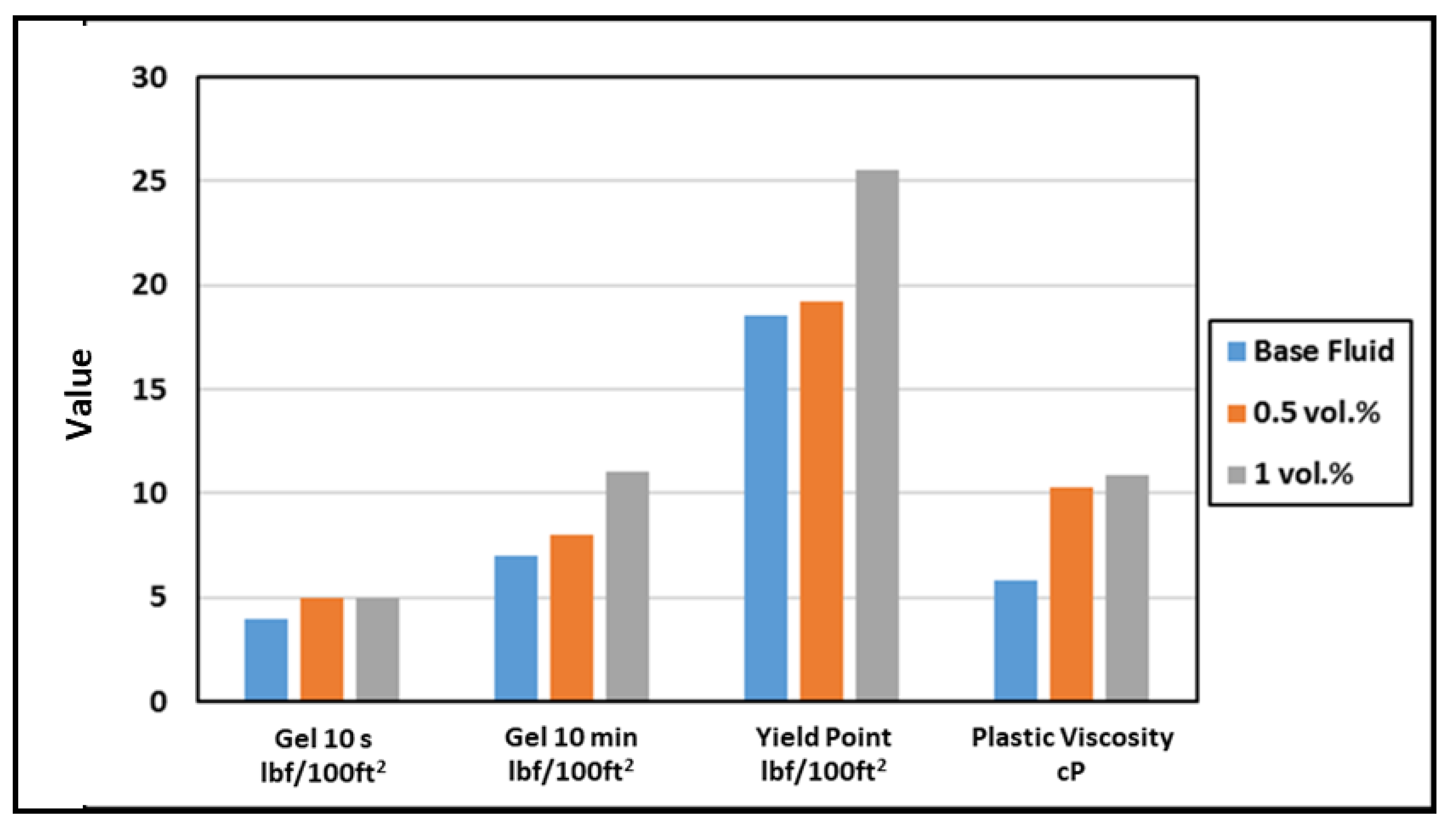
4.2. Rheological Analysis
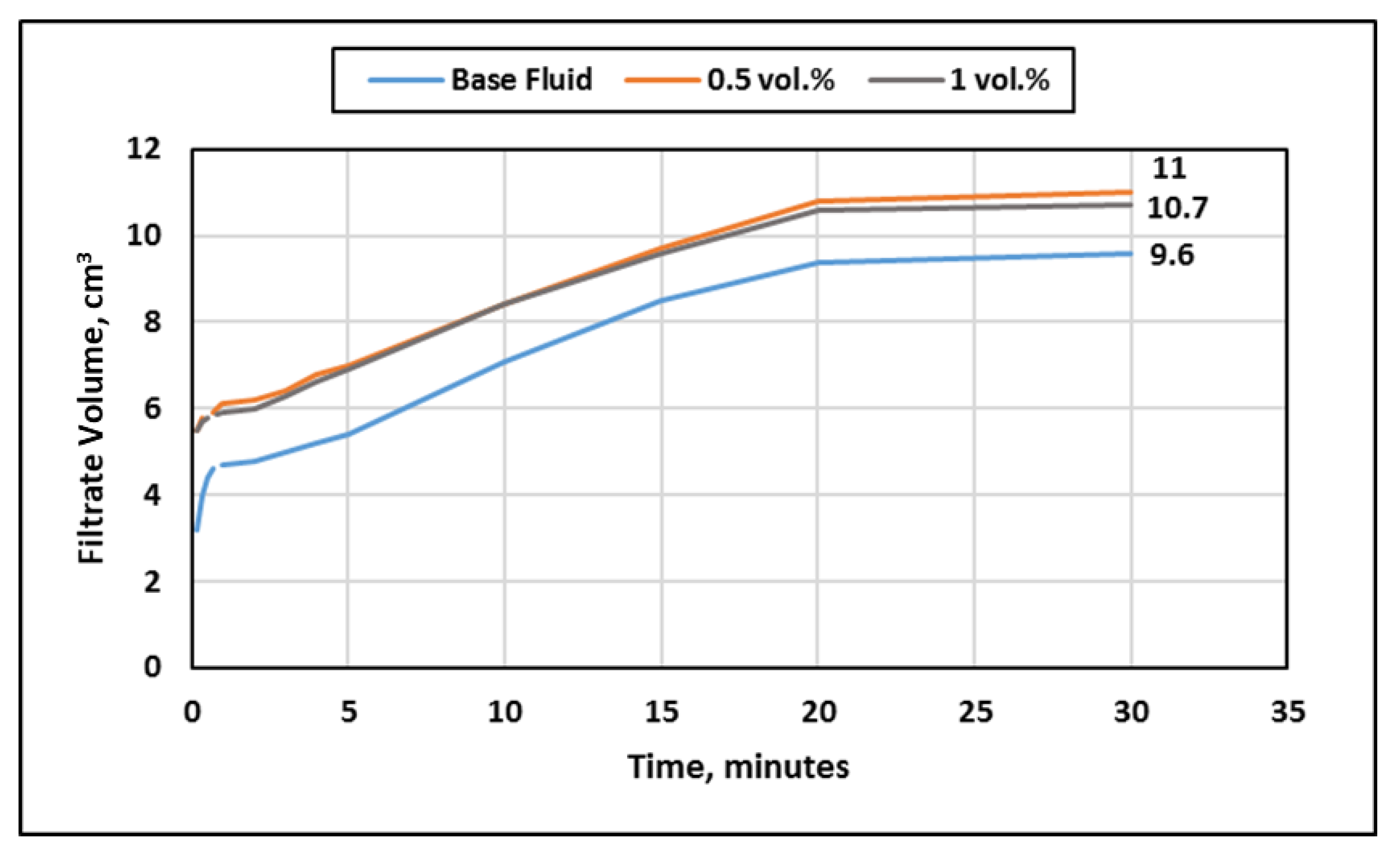
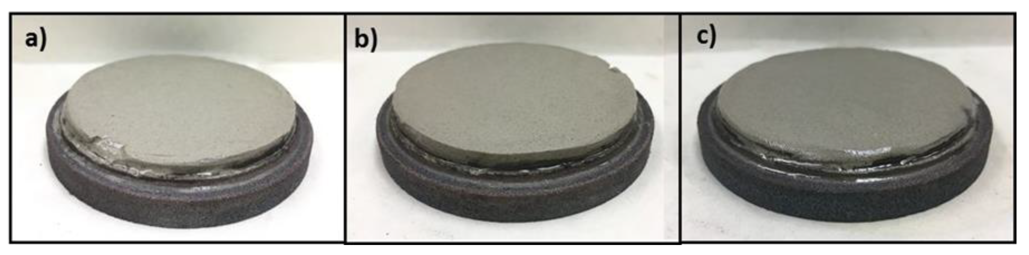
4.3. HPHT Filtration Experiments
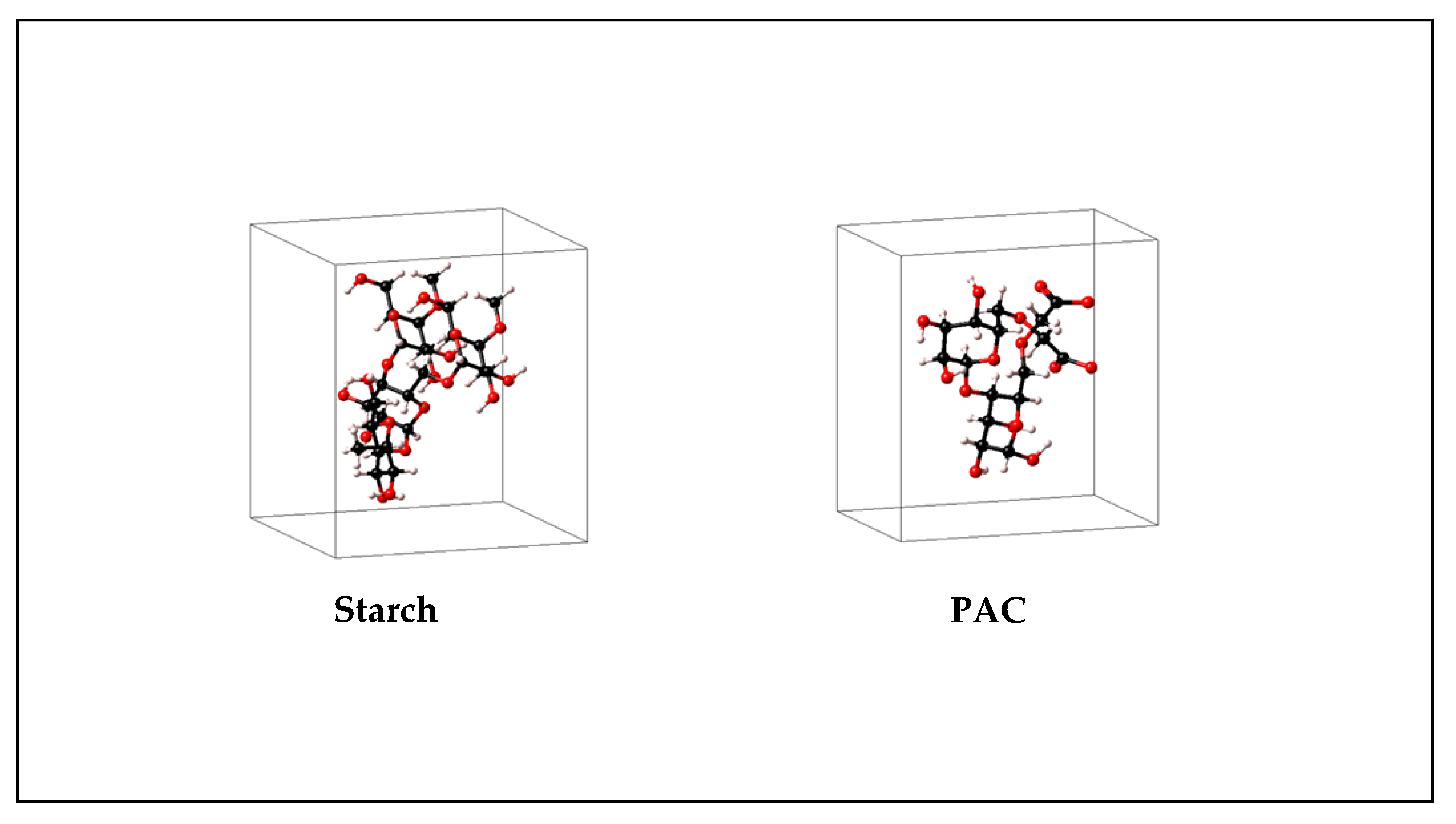
4.4. Molecular Investigation of Fluid Loss Control Agents
5. Summary and Conclusions
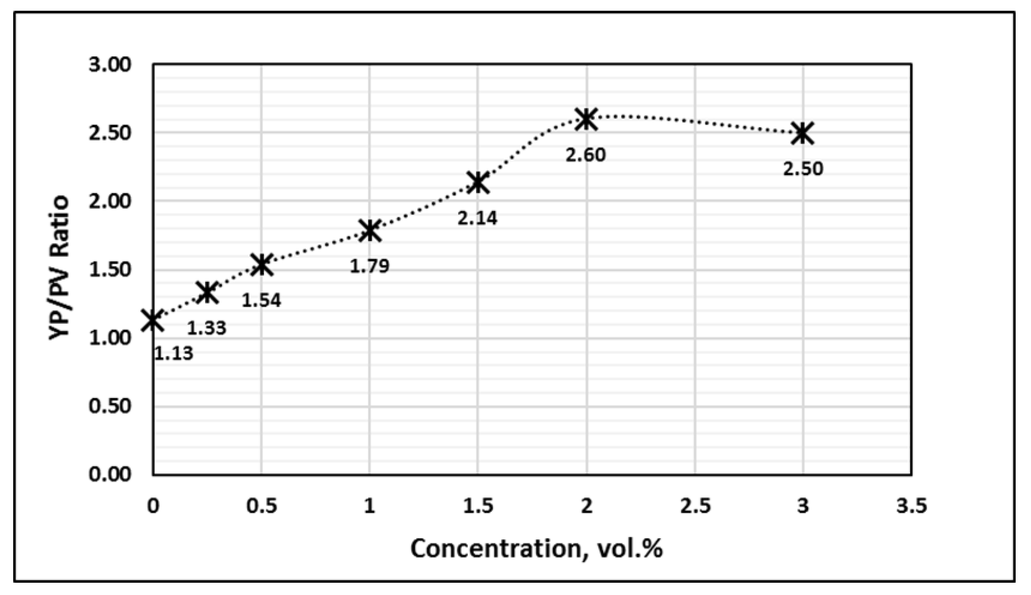
- Adding 0.5–1.0 vol.% of the urea-additive to the base drilling fluid increased the yield point and gel strength after 10 s at 80 °F by around 40–50%. Moreover, the plastic viscosity and gel strength after 10 min remained almost constant. At 250 °F, a 76% drop in the plastic viscosity was observed for the base drilling fluid, while the urea-additive reduced that drop to around 50% and maintained the YP/PV ratio at that temperature.
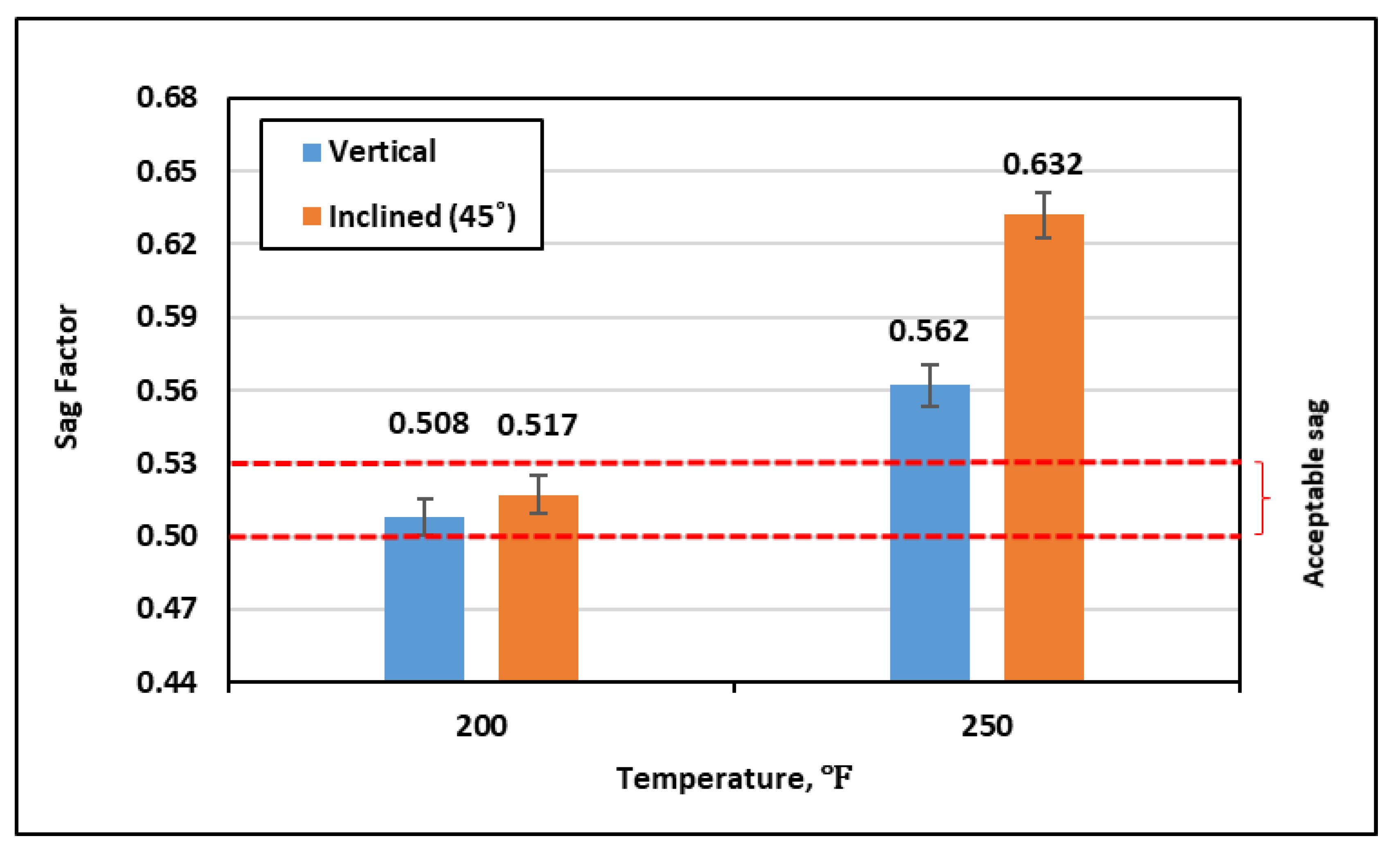
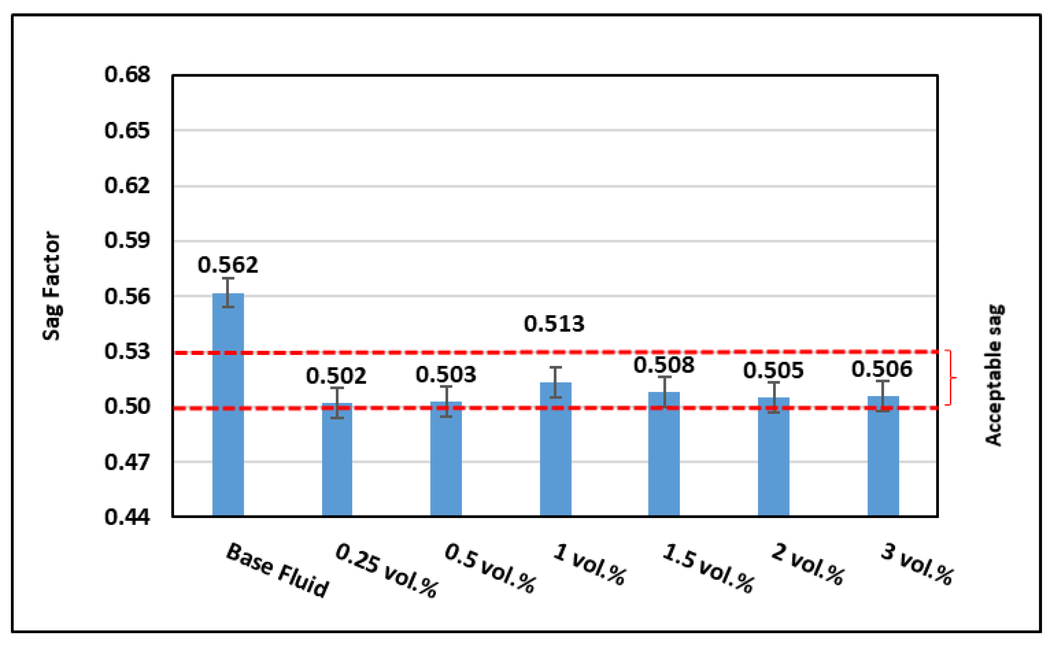
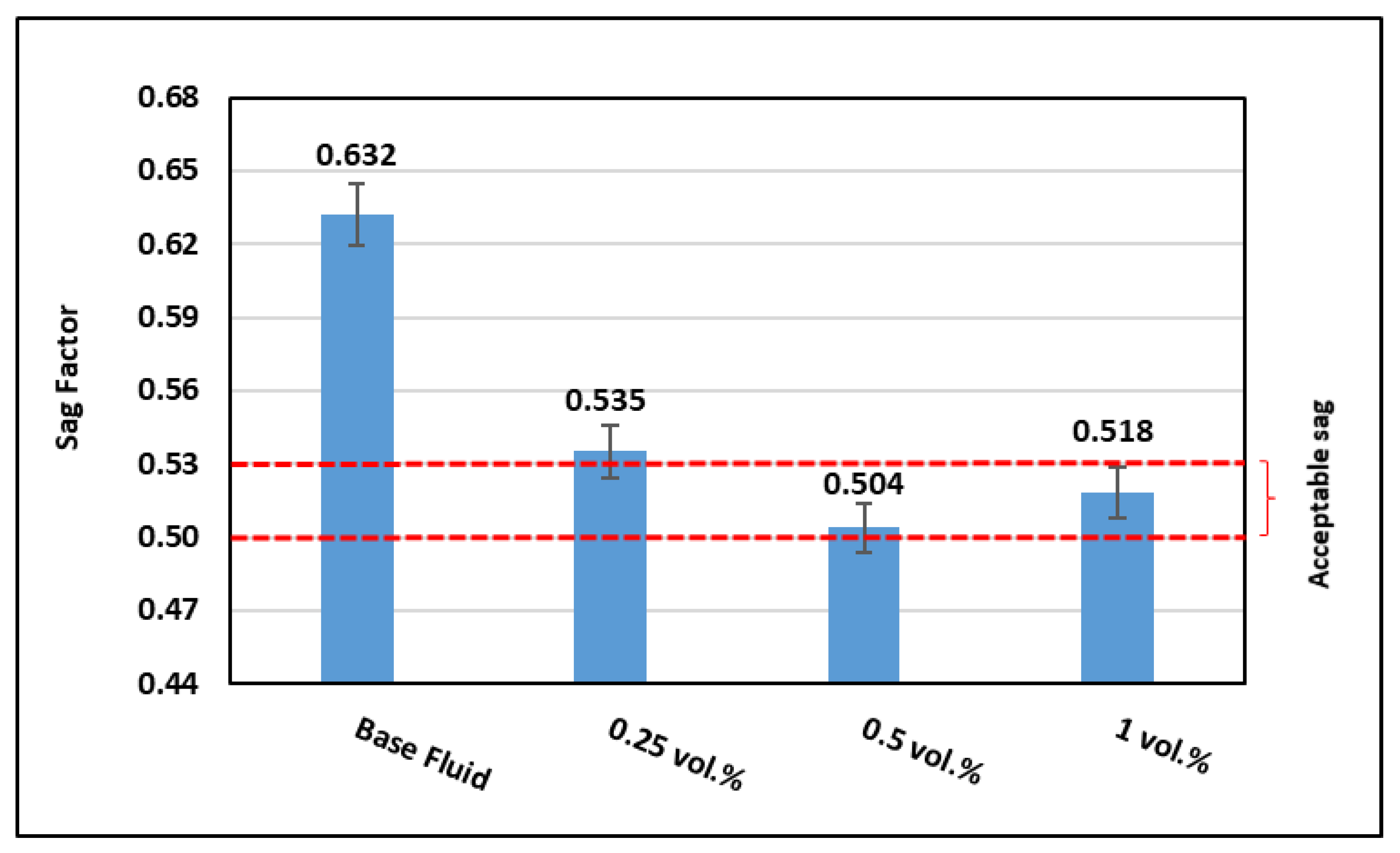
- Adding just 0.5–1.0 vol.% of the urea-additive was adequate to enhance the drilling fluid stability and prevent barite sag at 250 °F. The sag factor was around 0.51 under both vertical and inclined conditions.
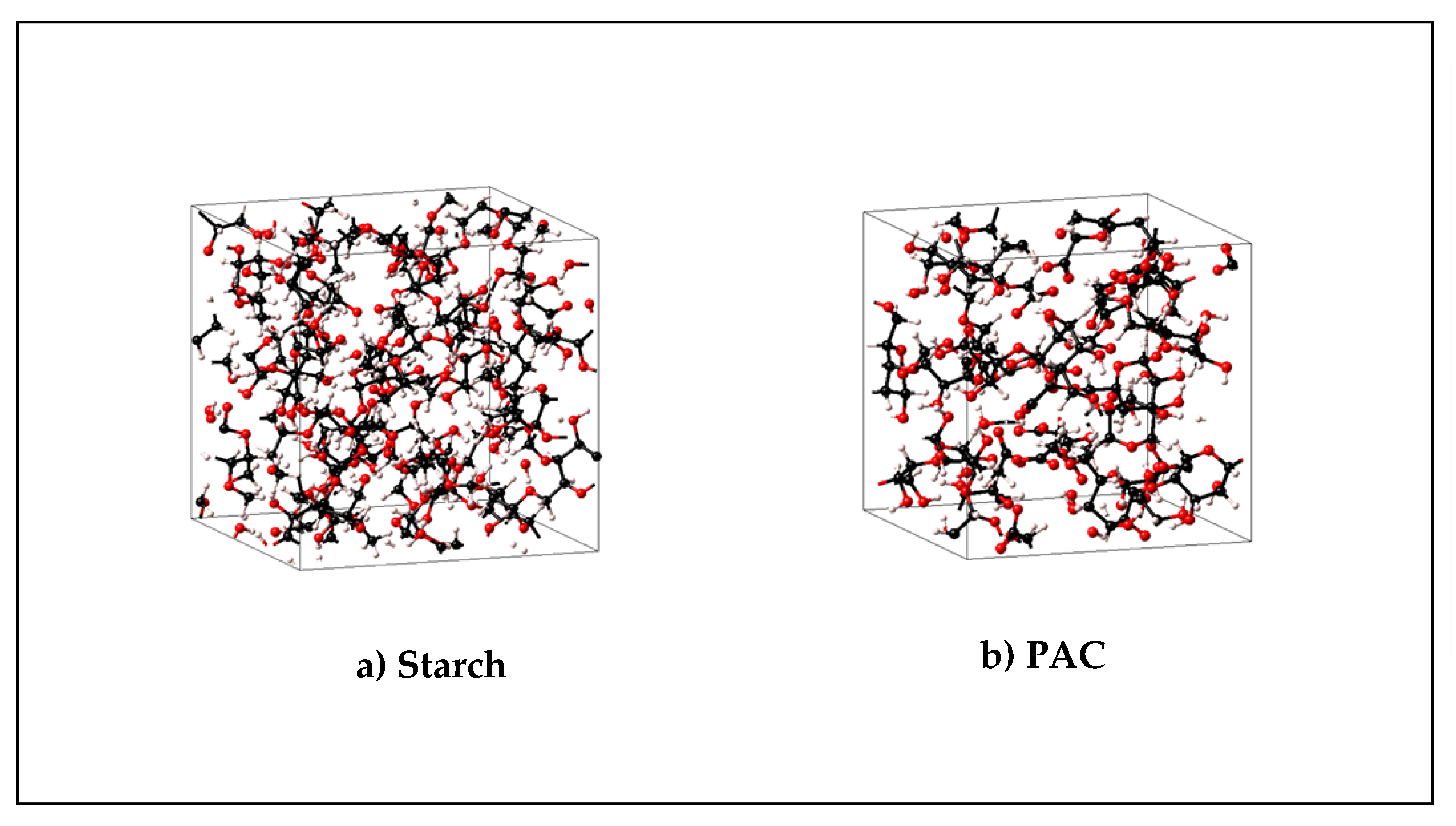
- The urea-additive had no impact on the density and the pH of the drilling fluid, while it had minimal effect on the filtration performance of the drilling fluids and the properties of the formed filter cake. The total fluid filtrate increased by around 1.4 cm3, while the filter cake properties were almost the same. However, fluid loss control agents such as starch and polyanionic cellulose can help in minimizing drilling fluid invasions. Molecular simulation of polymeric accumulations showed that a thin layer of low porosity is formed under typical reservoir conditions.
- The developed formulation can be used to drill deep formations efficiently without the barite sag issue at a temperature up to 250 °F. Furthermore, the concentration of the urea-additive should be optimized for different fluid formulations before using it in real field applications. More research work is needed to evaluate the performance of this urea-additive at higher solids loading, high salt concentrations, and ultra-high temperature and pressure. An experimental study is also needed to evaluate the interaction of this additive with formation rocks and fluids and how this may affect the formation damage.
Author Contributions
Funding
Acknowledgments
Conflicts of Interest
Appendix A
- i-
- Forcefield assignments

| Atom # | Name | Element | Atomic Number | Wycoff Position | Wycoff Equation | X | Y | Z | FF Atom Type | Charge |
|---|---|---|---|---|---|---|---|---|---|---|
| 1 | C1 | C | 6 | 1a | x,y,z | 0.172991 | 0.331875 | 0.762531 | c3 | −0.159 |
| 2 | C2 | C | 6 | 1a | x,y,z | 0.284569 | 0.331875 | 0.762531 | c1oe | 0.107 |
| 3 | C3 | C | 6 | 1a | x,y,z | 0.322175 | 0.240062 | 0.729939 | c43o | 0.107 |
| 4 | C4 | C | 6 | 1a | x,y,z | 0.290589 | 0.22067 | 0.623912 | c43o | 0.107 |
| 5 | C5 | C | 6 | 1a | x,y,z | 0.326374 | 0.281348 | 0.545539 | c1oe | 0.107 |
| 6 | C6 | C | 6 | 1a | x,y,z | 0.288937 | 0.374827 | 0.570667 | c1oe | 0.107 |
| 7 | O1 | O | 8 | 1a | x,y,z | 0.32222 | 0.401024 | 0.682899 | oc | −0.32 |
| 8 | C7 | C | 6 | 1a | x,y,z | 0.33047 | 0.440172 | 0.490167 | c4o | 0.054 |
| 9 | O2 | O | 8 | 1a | x,y,z | 0.295668 | 0.526854 | 0.513608 | oh | −0.57 |
| 10 | O3 | O | 8 | 1a | x,y,z | 0.430605 | 0.281129 | 0.546566 | oc | −0.32 |
| 11 | C8 | C | 6 | 1a | x,y,z | 0.466156 | 0.341441 | 0.468663 | coh | 0.267 |
| 12 | C9 | C | 6 | 1a | x,y,z | 0.390106 | 0.375597 | 0.388848 | c43o | 0.107 |
| 13 | C10 | C | 6 | 1a | x,y,z | 0.317198 | 0.426105 | 0.443868 | c43o | 0.107 |
| 14 | C11 | C | 6 | 1a | x,y,z | 0.354739 | 0.502569 | 0.497479 | c1oe | 0.107 |
| 15 | C12 | C | 6 | 1a | x,y,z | 0.429364 | 0.473545 | 0.581691 | c1oe | 0.107 |
| 16 | O4 | O | 8 | 1a | x,y,z | 0.511396 | 0.420495 | 0.527721 | oc | −0.32 |
| 17 | C13 | C | 6 | 1a | x,y,z | 0.472674 | 0.554988 | 0.635556 | c2oe | 0.054 |
| 18 | O5 | O | 8 | 1a | x,y,z | 0.541882 | 0.527929 | 0.713651 | oc | −0.32 |
| 19 | C14 | C | 6 | 1a | x,y,z | 0.582344 | 0.604008 | 0.76398 | coh | 0.267 |
| 20 | C15 | C | 6 | 1a | x,y,z | 0.686053 | 0.565391 | 0.756915 | c43o | 0.107 |
| 21 | C16 | C | 6 | 1a | x,y,z | 0.71063 | 0.550135 | 0.647774 | c43o | 0.107 |
| 22 | C17 | C | 6 | 1a | x,y,z | 0.710806 | 0.628485 | 0.583634 | c1oe | 0.107 |
| 23 | C18 | C | 6 | 1a | x,y,z | 0.608095 | 0.669659 | 0.58369 | c1oe | 0.107 |
| 24 | O6 | O | 8 | 1a | x,y,z | 0.577683 | 0.689814 | 0.698637 | oc | −0.32 |
| 25 | C19 | C | 6 | 1a | x,y,z | 0.60913 | 0.755165 | 0.519422 | c4o | 0.054 |
| 26 | O7 | O | 8 | 1a | x,y,z | 0.513789 | 0.793264 | 0.519565 | oh | −0.57 |
| 27 | O8 | O | 8 | 1a | x,y,z | 0.779177 | 0.690371 | 0.62576 | oc | −0.32 |
| 28 | C20 | C | 6 | 1a | x,y,z | 0.779346 | 0.768236 | 0.562002 | c3oe | 0.001 |
| 29 | O9 | O | 8 | 1a | x,y,z | 0.805773 | 0.511777 | 0.643664 | oh | −0.57 |
| 30 | O10 | O | 8 | 1a | x,y,z | 0.689893 | 0.483914 | 0.813656 | oh | −0.57 |
| 31 | O11 | O | 8 | 1a | x,y,z | 0.401198 | 0.559376 | 0.422602 | oc | −0.32 |
| 32 | C21 | C | 6 | 1a | x,y,z | 0.438511 | 0.63537 | 0.475895 | coh | 0.267 |
| 33 | C22 | C | 6 | 1a | x,y,z | 0.545024 | 0.603623 | 0.468663 | c43o | 0.107 |
| 34 | C23 | C | 6 | 1a | x,y,z | 0.572016 | 0.593898 | 0.359283 | c43o | 0.107 |
| 35 | C24 | C | 6 | 1a | x,y,z | 0.566907 | 0.674312 | 0.29918 | c1oe | 0.107 |
| 36 | C25 | C | 6 | 1a | x,y,z | 0.461274 | 0.708913 | 0.299555 | c1oe | 0.107 |
| 37 | O12 | O | 8 | 1a | x,y,z | 0.428021 | 0.722954 | 0.414885 | oc | −0.32 |
| 38 | C26 | C | 6 | 1a | x,y,z | 0.456466 | 0.796524 | 0.239715 | c4o | 0.054 |
| 39 | O13 | O | 8 | 1a | x,y,z | 0.358424 | 0.828522 | 0.240146 | oh | −0.57 |
| 40 | O14 | O | 8 | 1a | x,y,z | 0.629824 | 0.738754 | 0.345583 | oc | −0.32 |
| 41 | C27 | C | 6 | 1a | x,y,z | 0.624737 | 0.818671 | 0.285847 | c3oe | 0.001 |
| 42 | O15 | O | 8 | 1a | x,y,z | 0.669933 | 0.561773 | 0.35487 | oh | −0.57 |
| 43 | O16 | O | 8 | 1a | x,y,z | 0.554472 | 0.520613 | 0.521278 | oh | −0.57 |
| 44 | O17 | O | 8 | 1a | x,y,z | 0.246009 | 0.454598 | 0.368657 | oh | −0.57 |
| 45 | O18 | O | 8 | 1a | x,y,z | 0.344924 | 0.302505 | 0.33691 | oh | −0.57 |
| 46 | O19 | O | 8 | 1a | x,y,z | 0.323739 | 0.134175 | 0.596919 | oh | −0.57 |
| 47 | O20 | O | 8 | 1a | x,y,z | 0.284268 | 0.175102 | 0.800825 | oh | −0.57 |
| 48 | H1 | H | 1 | 1a | x,y,z | 0.146814 | 0.283559 | 0.818172 | hc | 0.053 |
| 49 | H2 | H | 1 | 1a | x,y,z | 0.146814 | 0.315869 | 0.684508 | hc | 0.053 |
| 50 | H3 | H | 1 | 1a | x,y,z | 0.146814 | 0.396197 | 0.784912 | hc | 0.053 |
| 51 | H4 | H | 1 | 1a | x,y,z | 0.310467 | 0.347728 | 0.840705 | hc | 0.053 |
| 52 | H5 | H | 1 | 1a | x,y,z | 0.400662 | 0.239352 | 0.733125 | hc | 0.053 |
| 53 | H6 | H | 1 | 1a | x,y,z | 0.212278 | 0.226087 | 0.623553 | hc | 0.053 |
| 54 | H7 | H | 1 | 1a | x,y,z | 0.300807 | 0.261604 | 0.468519 | hc | 0.053 |
| 55 | H8 | H | 1 | 1a | x,y,z | 0.210494 | 0.37589 | 0.566526 | hc | 0.053 |
| 56 | H9 | H | 1 | 1a | x,y,z | 0.307487 | 0.421597 | 0.411778 | hc | 0.053 |
| 57 | H10 | H | 1 | 1a | x,y,z | 0.408928 | 0.439422 | 0.494222 | hc | 0.053 |
| 58 | H11 | H | 1 | 1a | x,y,z | 0.224544 | 0.527531 | 0.509928 | ho | 0.41 |
| 59 | H12 | H | 1 | 1a | x,y,z | 0.517959 | 0.3054 | 0.421392 | hc | 0.053 |
| 60 | H13 | H | 1 | 1a | x,y,z | 0.425569 | 0.416737 | 0.331 | hc | 0.053 |
| 61 | H14 | H | 1 | 1a | x,y,z | 0.287014 | 0.383617 | 0.503795 | hc | 0.053 |
| 62 | H15 | H | 1 | 1a | x,y,z | 0.29569 | 0.537323 | 0.53516 | hc | 0.053 |
| 63 | H16 | H | 1 | 1a | x,y,z | 0.393835 | 0.433089 | 0.640184 | hc | 0.053 |
| 64 | H17 | H | 1 | 1a | x,y,z | 0.415248 | 0.592158 | 0.672863 | hc | 0.053 |
| 65 | H18 | H | 1 | 1a | x,y,z | 0.508438 | 0.595531 | 0.577326 | hc | 0.053 |
| 66 | H19 | H | 1 | 1a | x,y,z | 0.550038 | 0.624349 | 0.837726 | hc | 0.053 |
| 67 | H20 | H | 1 | 1a | x,y,z | 0.737255 | 0.611192 | 0.790925 | hc | 0.053 |
| 68 | H21 | H | 1 | 1a | x,y,z | 0.655164 | 0.507369 | 0.616027 | hc | 0.053 |
| 69 | H22 | H | 1 | 1a | x,y,z | 0.731228 | 0.611743 | 0.503827 | hc | 0.053 |
| 70 | H23 | H | 1 | 1a | x,y,z | 0.556938 | 0.62429 | 0.548772 | hc | 0.053 |
| 71 | H24 | H | 1 | 1a | x,y,z | 0.630756 | 0.741044 | 0.439265 | hc | 0.053 |
| 72 | H25 | H | 1 | 1a | x,y,z | 0.660089 | 0.800779 | 0.554228 | hc | 0.053 |
| 73 | H26 | H | 1 | 1a | x,y,z | 0.467595 | 0.751919 | 0.488001 | ho | 0.41 |
| 74 | H27 | H | 1 | 1a | x,y,z | 0.830871 | 0.814873 | 0.593741 | hc | 0.053 |
| 75 | H28 | H | 1 | 1a | x,y,z | 0.707547 | 0.797035 | 0.56201 | hc | 0.053 |
| 76 | H29 | H | 1 | 1a | x,y,z | 0.799753 | 0.751467 | 0.482203 | hc | 0.053 |
| 77 | H30 | H | 1 | 1a | x,y,z | 0.853186 | 0.553003 | 0.673254 | ho | 0.41 |
| 78 | H31 | H | 1 | 1a | x,y,z | 0.643477 | 0.442383 | 0.782833 | ho | 0.41 |
| 79 | H32 | H | 1 | 1a | x,y,z | 0.405228 | 0.650971 | 0.550787 | hc | 0.053 |
| 80 | H33 | H | 1 | 1a | x,y,z | 0.592159 | 0.651249 | 0.505842 | hc | 0.053 |
| 81 | H34 | H | 1 | 1a | x,y,z | 0.520367 | 0.548947 | 0.324445 | hc | 0.053 |
| 82 | H35 | H | 1 | 1a | x,y,z | 0.589516 | 0.661778 | 0.218959 | hc | 0.053 |
| 83 | H36 | H | 1 | 1a | x,y,z | 0.414162 | 0.661758 | 0.261491 | hc | 0.053 |
| 84 | H37 | H | 1 | 1a | x,y,z | 0.480081 | 0.786692 | 0.159295 | hc | 0.053 |
| 85 | H38 | H | 1 | 1a | x,y,z | 0.503358 | 0.843918 | 0.277684 | hc | 0.053 |
| 86 | H39 | H | 1 | 1a | x,y,z | 0.315914 | 0.785557 | 0.20573 | ho | 0.41 |
| 87 | H40 | H | 1 | 1a | x,y,z | 0.67215 | 0.867226 | 0.320813 | hc | 0.053 |
| 88 | H41 | H | 1 | 1a | x,y,z | 0.550897 | 0.842875 | 0.286086 | hc | 0.053 |
| 89 | H42 | H | 1 | 1a | x,y,z | 0.647339 | 0.806117 | 0.205626 | hc | 0.053 |
| 90 | H43 | H | 1 | 1a | x,y,z | 0.713691 | 0.604765 | 0.387334 | ho | 0.41 |
| 91 | H44 | H | 1 | 1a | x,y,z | 0.511749 | 0.477428 | 0.487579 | ho | 0.41 |
| 92 | H45 | H | 1 | 1a | x,y,z | 0.27695 | 0.492777 | 0.316273 | ho | 0.41 |
| 93 | H46 | H | 1 | 1a | x,y,z | 0.312765 | 0.265203 | 0.389334 | ho | 0.41 |
| 94 | H47 | H | 1 | 1a | x,y,z | 0.394914 | 0.132774 | 0.598385 | ho | 0.41 |
| 95 | H48 | H | 1 | 1a | x,y,z | 0.213115 | 0.175733 | 0.797958 | ho | 0.41 |
| Atom # | Name | Element | Atomic number | Wycoff Position | Wycoff Equation | X | Y | Z | FF Atom Type | Charge |
|---|---|---|---|---|---|---|---|---|---|---|
| 1 | C1 | C | 6 | 1a | x,y,z | 0.513163 | 0.722667 | 0.454071 | c2oe | 0.054 |
| 2 | C2 | C | 6 | 1a | x,y,z | 0.478942 | 0.669498 | 0.605049 | c1oe | 0.107 |
| 3 | C3 | C | 6 | 1a | x,y,z | 0.373177 | 0.710624 | 0.663953 | c43o | 0.107 |
| 4 | C4 | C | 6 | 1a | x,y,z | 0.285433 | 0.686912 | 0.550835 | c43o | 0.107 |
| 5 | C5 | C | 6 | 1a | x,y,z | 0.283075 | 0.577245 | 0.523724 | c43o | 0.107 |
| 6 | C6 | C | 6 | 1a | x,y,z | 0.38819 | 0.547862 | 0.463682 | coh | 0.267 |
| 7 | O1 | O | 8 | 1a | x,y,z | 0.467066 | 0.56636 | 0.577042 | oc | −0.32 |
| 8 | O2 | O | 8 | 1a | x,y,z | 0.392212 | 0.445572 | 0.43524 | oc | −0.32 |
| 9 | C7 | C | 6 | 1a | x,y,z | 0.502271 | 0.422312 | 0.406015 | c1oe | 0.107 |
| 10 | C8 | C | 6 | 1a | x,y,z | 0.568449 | 0.421539 | 0.558158 | c1oe | 0.107 |
| 11 | O3 | O | 8 | 1a | x,y,z | 0.533879 | 0.340712 | 0.666164 | oc | −0.32 |
| 12 | C9 | C | 6 | 1a | x,y,z | 0.521445 | 0.242076 | 0.587262 | coh | 0.267 |
| 13 | C10 | C | 6 | 1a | x,y,z | 0.455082 | 0.250801 | 0.441974 | c43o | 0.107 |
| 14 | C11 | C | 6 | 1a | x,y,z | 0.505278 | 0.322628 | 0.332261 | c43o | 0.107 |
| 15 | O4 | O | 8 | 1a | x,y,z | 0.613752 | 0.292302 | 0.295536 | oh | −0.57 |
| 16 | O5 | O | 8 | 1a | x,y,z | 0.446687 | 0.152222 | 0.369569 | oh | −0.57 |
| 17 | O6 | O | 8 | 1a | x,y,z | 0.625578 | 0.202517 | 0.54618 | oh | −0.57 |
| 18 | C12 | C | 6 | 1a | x,y,z | 0.566382 | 0.523731 | 0.651178 | c2oe | 0.054 |
| 19 | O7 | O | 8 | 1a | x,y,z | 0.582028 | 0.613623 | 0.546866 | oc | −0.32 |
| 20 | O8 | O | 8 | 1a | x,y,z | 0.26166 | 0.524457 | 0.670148 | oh | −0.57 |
| 21 | O9 | O | 8 | 1a | x,y,z | 0.183688 | 0.720195 | 0.613857 | oh | −0.57 |
| 22 | O10 | O | 8 | 1a | x,y,z | 0.380345 | 0.818516 | 0.687913 | oh | −0.57 |
| 23 | O11 | O | 8 | 1a | x,y,z | 0.616691 | 0.682099 | 0.380761 | oc | −0.32 |
| 24 | H1 | H | 1 | 1a | x,y,z | 0.523351 | 0.799982 | 0.478606 | hc | 0.053 |
| 25 | H2 | H | 1 | 1a | x,y,z | 0.451408 | 0.714894 | 0.370873 | hc | 0.053 |
| 26 | H3 | H | 1 | 1a | x,y,z | 0.535598 | 0.678615 | 0.693189 | hc | 0.053 |
| 27 | H4 | H | 1 | 1a | x,y,z | 0.355306 | 0.676198 | 0.772583 | hc | 0.053 |
| 28 | H5 | H | 1 | 1a | x,y,z | 0.300047 | 0.723987 | 0.443468 | hc | 0.053 |
| 29 | H6 | H | 1 | 1a | x,y,z | 0.223789 | 0.559367 | 0.440251 | hc | 0.053 |
| 30 | H7 | H | 1 | 1a | x,y,z | 0.405584 | 0.587928 | 0.359924 | hc | 0.053 |
| 31 | H8 | H | 1 | 1a | x,y,z | 0.534372 | 0.476054 | 0.327749 | hc | 0.053 |
| 32 | H9 | H | 1 | 1a | x,y,z | 0.648517 | 0.40696 | 0.526661 | hc | 0.053 |
| 33 | H10 | H | 1 | 1a | x,y,z | 0.483557 | 0.191738 | 0.665519 | hc | 0.053 |
| 34 | H11 | H | 1 | 1a | x,y,z | 0.378091 | 0.276975 | 0.472049 | hc | 0.053 |
| 35 | H12 | H | 1 | 1a | x,y,z | 0.460398 | 0.324803 | 0.227417 | hc | 0.053 |
| 36 | H13 | H | 1 | 1a | x,y,z | 0.657829 | 0.291458 | 0.395134 | ho | 0.41 |
| 37 | H14 | H | 1 | 1a | x,y,z | 0.502216 | 0.14579 | 0.283557 | ho | 0.41 |
| 38 | H15 | H | 1 | 1a | x,y,z | 0.680625 | 0.257874 | 0.554148 | ho | 0.41 |
| 39 | H16 | H | 1 | 1a | x,y,z | 0.629792 | 0.522485 | 0.732915 | hc | 0.053 |
| 40 | H17 | H | 1 | 1a | x,y,z | 0.493954 | 0.529905 | 0.714596 | hc | 0.053 |
| 41 | H19 | H | 1 | 1a | x,y,z | 0.300236 | 0.559503 | 0.759677 | ho | 0.41 |
| 42 | H20 | H | 1 | 1a | x,y,z | 0.154476 | 0.666592 | 0.687862 | ho | 0.41 |
| 43 | H21 | H | 1 | 1a | x,y,z | 0.372035 | 0.85421 | 0.58293 | ho | 0.41 |
| 44 | C13 | C | 6 | 1a | x,y,z | 0.638785 | 0.699253 | 0.631155 | c2oe | 0.054 |
| 45 | C14 | C | 6 | 1a | x,y,z | 0.721705 | 0.746325 | 0.527925 | c_1 | 0.003 |
| 46 | O12 | O | 8 | 1a | x,y,z | 0.693674 | 0.789124 | 0.393837 | o- | 0 |
| 47 | O13 | O | 8 | 1a | x,y,z | 0.833075 | 0.745494 | 0.575186 | o | −0.003 |
| 48 | C15 | C | 6 | 1a | x,y,z | 0.683434 | 0.618188 | 0.484962 | c2oe | 0.054 |
| 49 | C16 | C | 6 | 1a | x,y,z | 0.767156 | 0.540745 | 0.453012 | c_1 | 0.003 |
| 50 | O14 | O | 8 | 1a | x,y,z | 0.7701 | 0.494722 | 0.315753 | o- | 0 |
| 51 | O15 | O | 8 | 1a | x,y,z | 0.845524 | 0.516138 | 0.572953 | o | −0.003 |
| 52 | H22 | H | 1 | 1a | x,y,z | 0.744033 | 0.66319 | 0.435863 | hc | 0.053 |
| 53 | H23 | H | 1 | 1a | x,y,z | 0.636373 | 0.560931 | 0.432774 | hc | 0.053 |
| 54 | H24 | H | 1 | 1a | x,y,z | 0.675385 | 0.671506 | 0.733834 | hc | 0.053 |
| 55 | H25 | H | 1 | 1a | x,y,z | 0.58324 | 0.756603 | 0.661779 | hc | 0.053 |
- ii-
- He-Pycnometry Calculationswhere Nm and Na are the number of excess and adsorbed molecules of helium, respectively. VP is the pore volume, and ρa is the density of helium. Under the assumption of zero excess of molecules at such a degree of confinement, the above equation can be used to estimate the pore volume. Then, porosity can be calculated when VP is divided by the bulk volume. A summary of the calculations is given below:
| Pressure (bar) | Density (g/mL) | Molecular Volume (Å3/molecule) | Starch (molecule/box) | PAC (molecule/box) | VP starch (A3) | VP PAC (A3) | φ Starch | φ PAC |
|---|---|---|---|---|---|---|---|---|
| 0.1 | 1.62 × 10⁻⁵ | 411000.0 | 4.87 × 10⁻⁴ | 3.49 × 10⁻⁴ | 200.2 | 143.4 | 0.029 | 0.032 |
| 0.2 | 3.23 × 10⁻⁵ | 206000.0 | 1.00 × 10⁻³ | 6.91 × 10⁻⁴ | 206.0 | 142.3 | 0.030 | 0.032 |
| 0.3 | 4.85 × 10⁻⁵ | 137000.0 | 1.58 × 10⁻³ | 1.09 × 10⁻³ | 216.9 | 149.6 | 0.032 | 0.034 |
| 0.4 | 6.46 × 10⁻⁵ | 103000.0 | 2.11 × 10⁻³ | 1.44 × 10⁻³ | 216.9 | 148.4 | 0.032 | 0.033 |
| 0.5 | 8.08 × 10⁻⁵ | 82300.0 | 2.54 × 10⁻³ | 1.78 × 10⁻³ | 209.0 | 146.5 | 0.031 | 0.033 |
| 0.6 | 9.69 × 10⁻⁵ | 68600.0 | 3.02 × 10⁻³ | 2.17 × 10⁻³ | 207.2 | 148.9 | 0.030 | 0.033 |
| 0.7 | 1.13 × 10⁻⁴ | 58800.0 | 3.64 × 10⁻³ | 2.50 × 10⁻³ | 214.0 | 147.0 | 0.031 | 0.033 |
| 0.8 | 1.29 × 10⁻⁴ | 51400.0 | 4.09 × 10⁻³ | 2.74 × 10⁻³ | 210.2 | 140.8 | 0.031 | 0.032 |
| 0.9 | 1.45 × 10⁻⁴ | 45700.0 | 4.52 × 10⁻³ | 3.21 × 10⁻³ | 206.6 | 146.7 | 0.030 | 0.033 |
| 1 | 1.61 × 10⁻⁴ | 41200.0 | 5.02 × 10⁻³ | 3.53 × 10⁻³ | 206.8 | 145.4 | 0.030 | 0.033 |
References
- Bourgoyne, A.T.; Chenevert, M.E.; Millheim Keith, K.; Young, F.S. Applied Drilling Engineering; Society of Petroleum Engineers: Richardson, TX, USA, 1986; Chapter 2; p. 514. ISBN 9781555630010. [Google Scholar]
- Hossain, M.E.; Al-Majed, A.A. Fundamentals of Sustainable Drilling Engineering; Scrivener Publishing LLC: Beverly, MA, USA, 2015; ISBN 9780470878170. [Google Scholar]
- Sloan, J.P.; Brooks, J.P.; Dear, S.F., III. A New, Nondamaging, Acid-Soluble Weighting Material. J. Pet. Technol. 1975, 27, 15–20. [Google Scholar] [CrossRef]
- Tuntland, O.B.; Herfjord, H.J.; Lehne, K.A.; Haaland, E. Iron oxide as Weight Materials for Drilling Muds. Erdoel-Erdgas Z. 1981, 97, 300–302. Available online: https://www.osti.gov/etdeweb/biblio/5832121 (accessed on 20 January 2020).
- Walker, C.O. Alternative Weighting Material. J. Pet. Technol. 1983, 35, 2158–2164. [Google Scholar] [CrossRef]
- Al-Yami, A.S.; Nasr-El-Din, H.A. An Innovative Manganese Tetra-Oxide/KCl Water-Based Drill-in Fluids for HT/HP Wells. In Proceedings of the SPE Annual Technical Conference and Exhibition, Anaheim, CA, USA, 11–14 November 2007. SPE-110638. [Google Scholar] [CrossRef]
- Caenn, R.; Darley, H.C.H.; Gray, G.R. Composition and Properties of Drilling and Completion Fluids, 6th ed.; Gulf Professional Publishing: Houston, TX, USA; The Boulevard: Oxford, UK, 2011; Chapter 11; p. 535. ISBN 9780123838582. [Google Scholar]
- Al-Bagoury, M.; Steele, C.D. A New, Alternative Weight Material for Drilling Fluids. In Proceedings of the IADC/SPE Drilling Conference and Exhibition, San Diego, CA, USA, 6–8 March 2012. SPE-151331-MS. [Google Scholar] [CrossRef]
- Xiao, J.; Nasr-El-Din, H.A.; Al-Bagoury, M. Evaluation of Micronized Ilmenite as a Weighting Material in Oil-based Drilling Fluids for HPHT Applications. In Proceedings of the SPE European Formation Damage Conference and Exhibition, Noordwijk, The Netherlands, 5–7 June 2013. SPE-165184-MS. [Google Scholar] [CrossRef]
- Tehrani, A.; Cliffe, A.; Hodder, M.H.; Young, S.; Lee, J.; Stark, J.; Seale, S. Alternative Drilling Fluid Weighting Agents: A Comprehensive Study on Ilmenite and Hematite. In Proceedings of the IADC/SPE Drilling Conference and Exhibition, Fort Worth, TX, USA, 4–6 March 2014. SPE-167937-MS. [Google Scholar] [CrossRef]
- Nguyen, T.; Miska, S.; Yu, M.; Takach, N. Predicting Dynamic Barite Sag in Newtonian-Oil Based Drilling Fluids in Pipe. In Proceedings of the SPE Annual Technical Conference and Exhibition, New Orleans, LA, USA, 4–7 October 2009. SPE-124137-MS. [Google Scholar] [CrossRef]
- Ba Geri, B.S.; Mahmoud, M.A.; Abdulraheem, A.; Al-Mutairi, S.H.; Shawabkeh, R.A. Single stage filter cake removal of barite weighted water based drilling fluid. J. Pet. Sci. Eng. 2016, 149, 476–484. [Google Scholar] [CrossRef]
- Mohamed, A.K.; Elkatatny, S.A.; Mahmoud, M.A.; Shawabkeh, R.A.; Al-Majed, A.A. The Evaluation of Micronized Barite as a Weighting Material for Completing HPHT Wells. In Proceedings of the SPE Middle East Oil & Gas Show and Conference, Manama, Bahrain, 6–9 March 2017. SPE183768-MS. [Google Scholar] [CrossRef]
- Moajil, A.M.; Nasr-El-Din, H.A. Formation Damage Caused by Improper Mn3O4-based Filter Cake Cleanup Treatments. In Proceedings of the SPE European Formation Damage Conference, Noordwijk, The Netherlands, 7–10 June 2011. SPE-144179-MS. [Google Scholar] [CrossRef]
- Al-Yami, A.S.; Nasr-El-Din, H.A.; Al-Shafei, M.A.; Bataweel, M.A. Impact of Water-Based Drilling-In Fluids on Solids Invasion and Damage Characteristics. Spe Prod. Oper. 2013, 25, 40–49. [Google Scholar] [CrossRef]
- Bern, P.A.; Oort, E.V.; Neustadt, B.; Ebeltoft, H.; Zurdo, C.; Zamora, M.; Slater, K.S. Barite Sag: Measurement, Modeling, and Management. Spe Drill. Completion 2000, 15, 25–30. [Google Scholar] [CrossRef]
- Omland, T.H.; Saasen, A.; Zwaag, C.; Amundsen, P.A. The Effect of Weighting Material Sag on Drilling Operation Efficiency. In Proceedings of the SPE Asia Pacific Oil & Gas Conference and Exhibition, Jakarta, Indonesia, 30 October–1 November 2007. SPE-110537-MS. [Google Scholar] [CrossRef]
- Hanson, P.M.; Trigg, T.K.; Rachal, G.; Zamora, M. Investigation of Barite “Sag” in Weighted Drilling Fluids in Highly Deviated Wells. In Proceedings of the 65th Annual Technical Conference and Exhibition, New Orleans, LA, USA, 23–26 September 1990. Paper SPE-20423-MS. [Google Scholar] [CrossRef]
- Scott, P.D.; Zamora, M.; Aldea, C. Barite-Sag Management: Challenges, Strategies, Opportunities. In Proceedings of the IADC/SPE Drilling Conference, Dallas, TX, USA, 2–4 March 2004. SPE-87136-MS. [Google Scholar] [CrossRef]
- Saasen, A.; Jordal, O.H.; Burkhead, D.; Berg, P.C.; Løklingholm, G.; Pedersen, E.S.; Turner, J.; Harris, M.J. Drilling HT/HP Wells Using a Cesium Formate Based Drilling Fluid. In Proceedings of the IADC/SPE Drilling Conference, Dallas, TX, USA, 26–28 February 2002. SPE-74541-MS. [Google Scholar] [CrossRef]
- Temple, C.; Paterson, F.; Leith, D. Method for Reducing Sag in Drilling, Completion, and Workover Fluids. WO Patent WO 2004/113467A1, 29 December 2004. [Google Scholar]
- Davis, C.; Livanec, P.; Shumway, W. Additive to Enhance Sag Stability of Drilling Fluid. WO Patent WO 2017/188946 A1, 2 November 2017. [Google Scholar]
- Basfar, S.; Elkatatny, S.; Mahmoud, M.; Kamal, M.S.; Murtaza, M.; Stanitzek, T. Prevention of Barite Sagging while Drilling High-Pressure High-Temperature (HPHT) Wells. In Proceedings of the SPE Kingdom of Saudi Arabia Annual Technical Symposium and Exhibition, Dammam, Saudi Arabia, 23–26 April 2018. SPE-192198-MS. [Google Scholar] [CrossRef]
- Elkatatny, S.M. Enhancing the Stability of Invert Emulsion Drilling Fluid for Drilling in High-Pressure High-Temperature Conditions. Energies 2018, 11, 2393. [Google Scholar] [CrossRef]
- Boyou, N.V.; Ismail, I.; Wan Sulaiman, W.R.; Sharifi, H.A.; Husein, N.; Hui, H.T.; Nadaraja, K. Experimental investigation of hole cleaning in directional drilling by using nano-enhanced water-based drilling fluids. J. Pet. Sci. Eng. 2019, 176, 220–231. [Google Scholar] [CrossRef]
- Alabdullatif, Z.; Al-Yami, A.; Wagle, V.; Bubshait, A.; Al-Safran, A. Development of New Kill Fluids with Minimum Sagging Problems for High-Pressure Jilh Formation in Saudi Arabia. Saudi Aramco J. Technol. 2015. [Google Scholar] [CrossRef]
- Basfar, S.; Mohamed, A.; Elkatatny, S.; Al-Majed, A. A combined barite-ilmenite weighting material to prevent barite sag in water-based drilling fluid. Materials 2019, 12, 1945. [Google Scholar] [CrossRef] [PubMed]
- Mohamed, A.; Basfar, S.; Elkatatny, S.; Al-Majed, M. Prevention of Barite Sag in Oil-Based Drilling Fluids Using a Mixture of Barite and Ilmenite as Weighting Material. Sustainability 2019, 11, 5617. [Google Scholar] [CrossRef]
- Mahmoud, M.A.; Al-Mutairi, S.H.; Abdulraheem, A. Effect of Sand Content on the Filter Cake Properties and Removal During Drilling Maximum Reservoir Contact Wells in Sandstone Reservoir. J. Energy Resour. Technol. 2016, 138, 32901. [Google Scholar] [CrossRef]
- Nagelsdiek, R.; Buhne, S.; Gaul, S.; Jacobs, B.; Karwath, V. Urea-Group- and/or Urethane Group-Containing Amides as and in Rheology Control Agents, Their Preparation and Their Use. WO Patent WO 2018/138236A1, 2 August 2018. [Google Scholar]
- Karlheinz, H.; Ulrich, O.; Axel, W.; Heribert, H.; Christoph, B. Rheologically Active Urea Urethane Compounds. U.S. Patent US6617468B2, 22 September 2002. [Google Scholar]
- Maxey, J. Rheological Analysis of Static and Dynamic Sag in Drilling Fluids. Annu. Trans. Nord. Rheol. Soc. 2007, 15, 181. [Google Scholar]
- Skalle, P.; Backe, K.R.; Lyomov, S.K.; Sveen, J. Barite Segregation in Inclined Boreholes. J. Can. Pet. Technol. 1999, 38. [Google Scholar] [CrossRef]
- Lahalih, S.M.; Dairanieh, I.S. Development of novel polymeric drilling mud dispersants. Eur. Polym. J. 1988, 25, 187–192. [Google Scholar] [CrossRef]
- Power, D.; Zamora, M. Drilling Fluid Yield Stress: Measurement Techniques for Improved Understanding of Critical Drilling Fluid Parameters. In Proceedings of the AADE National Technology Conference, Houston, TX, USA, 1–3 April 2003. AADE-03-NTCE-35. [Google Scholar]
- Chilingarian, G.; Alp, E.; Uslu, S.; Gonzales, S.; Ronald, J. Drilling Fluid Evaluation Using Yield Point-Plastic Viscosity Correlation; Paper SPE 12469; Society of Petroleum Engineers: Richardson, TX, USA, 27 July 1983. [Google Scholar]
- Wang, Z.; Bai, Y.; Zhang, H.; Liu, Y. Investigation on gelation nucleation kinetics of waxy crude oil emulsions by their thermal behavior. J. Pet. Sci. Eng. 2019, 181, 106230. [Google Scholar] [CrossRef]
- Rui, Z.; Guo, T.; Feng, Q.; Qu, Z.; Qi, N.; Gong, F. Influence of gravel on the propagation pattern of hydraulic fracture in the glutenite reservoir. J. Pet. Sci. Eng. 2018, 165, 627–639. [Google Scholar] [CrossRef]


| Study | Method | Drilling Fluid System | Findings |
|---|---|---|---|
| Temple et al., 2004 | Adding polyalkyl methacrylate | Oil-based | The optimum concentration to prevent barite sag was 0.5–3 lb/bbl. |
| Davis et al., 2017 | Adding polyethylene glycol (PEG) | Oil-based | A concentration of 0.5 lb/bbl was enough to eliminate barite sag. |
| Basfar et al., 2018 | Adding a copolymer | Oil-based | A concentration of 1 lbm/bbl of copolymer was enough to prevent barite sag up to 350°F. |
| Elkatatny, 2019 | |||
| Boyou et al., 2019 | Adding nano-silica | Water-based | The cuttings’ transport efficiency was significantly improved in different inclination angles. |
| Alabdullatif et al., 2015 | Adding a combination of Mn3O4 and barite as a weighting material | Water-based | Mn3O4 effectively enhanced the fluid stability and minimized barite sag. |
| Mohamed et al., 2017 | Using micronized barite | Water-based | Micronized barite improved the stability, but it did not eliminate barite sag. |
| Basfar et al., 2019 | Using a barite-ilmenite combined weighting material | Water-based | A proportion of 50 wt.% ilmenite (of the total weighting material) was adequate to prevent barite sag. |
| Mohamed et al., 2019 | Oil-based | A proportion of 40 wt.% ilmenite (of the total weighting material) was adequate to prevent barite sag. |
| Element | wt.% |
|---|---|
| Si | 1.9916 |
| S | 12.6341 |
| K | 0.6331 |
| Ca | 0.1109 |
| Fe | 1.3338 |
| Ni | 0.0157 |
| Cu | 0.0354 |
| Sr | 0.5518 |
| Mo | 0.017 |
| Ba | 82.6171 |
| Ta | 0.023 |
| Pb | 0.0366 |
| Parameter | Description |
|---|---|
| Main components |
|
| Density | 1.11 g/cc |
| Dynamic viscosity | 770 mPa.s |
| Water solubility | Completely miscible |
| Flash point | > 212 °F |
| Component | Amount, g | Mixing Time, min | Function |
|---|---|---|---|
| Water | 245 | - | Base |
| Defoamer (D-Air 4000L™) | 0.08 | 1 | Anti-foam agent |
| Soda ash | 0.5 | 1 | Maintains calcium concentration |
| Xanthan gum polymer | 1.5 | 20 | Viscosity control |
| Bentonite | 4 | 10 | Viscosity control |
| Potassium hydroxide | 0.5 | 1 | pH adjustment |
| Starch | 6 | 10 | Fluid loss control |
| PAC-R | 1 | 10 | Fluid loss control |
| Potassium chloride | 20 | 10 | Clay stabilization |
| Calcium carbonate | 5 | 10 | Bridging agent |
| Barite | 350 | 10 | Weighting material |
| Parameter | Description |
|---|---|
| Fluid volume | 350 cm3 |
| Pressure | 300 psi |
| Temperature | 250 °F |
| Experiment duration | 30 min |
| Ceramic filter disc | 50-micron |
| Parameter | Base Fluid | 0.5 vol.% | 1.0 vol.% |
|---|---|---|---|
| Filtrate volume, cm3 | 9.6 | 11 | 10.7 |
| Filter cake weight, g | 29.1 | 34.94 | 29.77 |
| Filter cake thickness, mm | 3.6 | 4.2 | 3.6 |
© 2020 by the authors. Licensee MDPI, Basel, Switzerland. This article is an open access article distributed under the terms and conditions of the Creative Commons Attribution (CC BY) license (http://creativecommons.org/licenses/by/4.0/).
Share and Cite
Mohamed, A.; Al-Afnan, S.; Elkatatny, S.; Hussein, I. Prevention of Barite Sag in Water-Based Drilling Fluids by A Urea-Based Additive for Drilling Deep Formations. Sustainability 2020, 12, 2719. https://doi.org/10.3390/su12072719
Mohamed A, Al-Afnan S, Elkatatny S, Hussein I. Prevention of Barite Sag in Water-Based Drilling Fluids by A Urea-Based Additive for Drilling Deep Formations. Sustainability. 2020; 12(7):2719. https://doi.org/10.3390/su12072719
Chicago/Turabian StyleMohamed, Abdelmjeed, Saad Al-Afnan, Salaheldin Elkatatny, and Ibnelwaleed Hussein. 2020. "Prevention of Barite Sag in Water-Based Drilling Fluids by A Urea-Based Additive for Drilling Deep Formations" Sustainability 12, no. 7: 2719. https://doi.org/10.3390/su12072719
APA StyleMohamed, A., Al-Afnan, S., Elkatatny, S., & Hussein, I. (2020). Prevention of Barite Sag in Water-Based Drilling Fluids by A Urea-Based Additive for Drilling Deep Formations. Sustainability, 12(7), 2719. https://doi.org/10.3390/su12072719