1. Introduction
There is a current need in the acoustic market to incorporate sustainable materials as alternatives to glass, mineral, and ceramic fibrous materials, all of which have high carbon footprints [
1]. Public awareness and concern about the negative effects of pollution have led consumers to favor environmentally friendly materials, less contaminating processes, and recycled products [
2]. In this sense, the concept of “green” building materials is currently used in several European countries. These countries have introduced specific recommendations into building regulations to increase the use of ecological materials in new constructions. These regulations also contain a list of non-sustainable materials that should be avoided (e.g., mineral fibers). In addition, some countries have developed standard eco-indicators to express the total environmental load of a product or process. All these numbers show that sound absorbing materials based on fiberglass and mineral wool report high environmental impacts, mainly due to their embodied energies [
3]. Moreover, Toyoda et al. [
4] have pointed out some of the environmental drawbacks of using fiberglass as a sound-absorbing material, including durability issues, difficult recycling, and that its dust is harmful to humans. The acoustic characterization of green materials has been discussed by Iannace [
5] and a comprehensive review on acoustical eco-materials can be found in [
2].
A thin layer of fibrous material can be added to a bulk sound-absorbing material in the form of an attached membrane. This layer is commonly used for the protection and structural integrity of the material. However, since this layer must be permeable so as not to degrade the acoustic performance, the membrane can also add acoustic resistance to the overall system, providing an increase in the total sound absorption. Thus, a nanofibrous layer with its unique properties has the potential to work well as a thin, lightweight absorbing solution.
Contrary to conventionally used microscale sound absorbers, sound absorbing membranes based on submicron fibers may show higher sound absorption abilities. As the membrane is forced to vibrate by incident sound waves, there are several physical mechanisms contributing to sound absorption. The kinetic energy of the membrane is transformed into thermal energy due to the friction between individual fibers, as well as the friction of the membrane with air and possibly with other layers of material arranged in its proximity. A certain part of the energy can also be transmitted to the frame (if it is present). In addition, part of the energy can be absorbed by scattering from the fibers and by the vibration caused in individual fibers or fiber segments (considering structural overlaps) [
6]. These unique properties come from the nature of nanofibrous layers, i.e., their small fibrous diameter, correspondingly high specific surface area, and high values of porosity, close to unity. This causes high viscous losses inside the material and, consequently, more dissipation of acoustic energy. Furthermore, due to resonance at its natural frequency, the membrane is able to absorb low-frequency sound energy. For thicker membranes, the effect of bending stiffness may have to be considered [
7]. Nanofibrous elements and the optimal rigidity of the membrane can lead an acoustic system to vibrate more efficiently [
8,
9].
The theoretical basis of the sound absorption characteristics of a membrane sound absorber has been presented by Sakagami et al. [
10]. To analyze the absorption mechanism, the solution is approached in a form that points out the contribution from each element of a membrane. The effects of the parameters of the sound absorption system are discussed in light of the calculated results. Another study [
11] reported a detailed analysis of the acoustic properties of a single-leaf permeable membrane and considered the effects of membrane parameters, such as surface density and airflow resistance. The statistical sound absorption coefficients of permeable membranes of different airflow resistance and sizes have been presented more recently [
12]. On the other hand, Toyoda et al. [
4] have presented a numerical method to predict the sound absorption performance of cylindrical and rectangular permeable membrane space sound absorbers. Kalinova [
9] has demonstrated that the nanofibrous layer has a resonant effect on sound absorption when the nanofibers are arranged with respect to the layer. This study reported that the sound absorption coefficient of a material composed of a nanofibrous web was significantly higher at lower frequencies than that of the basic material without nanofibers. It was also shown that the resonance frequency of a polyvinyl alcohol (PVA) nanofibrous membrane decreased with increases in its area density and the average diameter of the nanofibers.
The effectiveness of a fiber-based sound absorption material involves several parameters such as porosity, tortuosity, fiber diameter, surface density, and thickness [
13]. The optimization of material types, the structural characteristics of nanofibrous membranes, and their sound absorption mechanisms are of increasing interest. Typically, for textile materials applied as acoustic fabrics, the influence of airflow resistivity and area weight on the acoustic performance is very important [
14]. Although some studies have addressed the subject, further research is still needed on the inner structure mechanisms [
15,
16,
17,
18]. A nanofibrous membrane (which is already covered by a patent) can improve the ambient sound field quality by absorbing undesired noise [
19]. It can be successfully applied in numerous areas, including room acoustics and construction, automotive, transportation, aerospace, and, interestingly today, as a solution to reduce the noise coming out of drones [
1,
20,
21,
22].
Resonant nanofibrous membranes of very small thicknesses can be prepared from different polymer solutions in the form of electrospun nanofibers captured on a substrate layer via the electrospinning method. Electrospinning is one of the most popular methods to directly produce nanofibers. Most electrospinning setups include a feeding unit that transports the polymeric solution/melt into an electrical field. Details of the electrospinning technique are widely discussed in the literature [
23,
24].
Electrospinning methods can be divided into two groups: needle and needleless electrospinning. In a single-needle electrospinning system, the polymeric solution is stored inside a needle that is connected to a high-voltage supplier. A syringe pump feeds the solution to the needle tip. Micro- and nanometric fiber size can be produced with this technique by controlling the properties of the polymeric solution and parameters such as voltage applied, distance between electrodes (tip to collector), solution feed rate, needle tip diameter, and ambient conditions [
23,
24]. In comparison with needle electrospinning systems, needleless electrospinning systems offer certain advantages, such as preventing needle clogging and avoiding the limiting distance between needles [
23].
Both rotating roller and wire electrospinning systems are currently used on an industrial scale under the trade name Nanospider [
25]. Although the role played by the system and process parameters of the roller electrospinning technique in the final product have been discussed [
26], the parameters for wire electrospinning, which has been used in this study, still have yet to be fully investigated [
24,
26,
27].
Regarding environmental problems, one of the major challenges in the development of electrospinning as a manufacturing technology is the issue of the solvents used to dissolve the polymer, which are predominantly organic [
28]. Volatilization of these solvents during the spinning process may be hazardous. It is evident that systems that employ water as a solvent offer many advantages in terms of safety, costs, and sustainability. However, water is usually not a favorable solvent for electrospinning because of its high dielectric constant. Although some non-solvent alternative techniques have been suggested, the use of water-soluble polymers in the electrospinning process appears to be the most convenient and sustainable approach [
23,
24,
28,
29].
Therefore, a green electrospinning strategy should consider the use of environmentally friendly and biodegradable raw materials, and the solution used for electrospinning must be non-toxic and pollution-free. Nanoscopic fibers fabricated in such a manner will be sustainable and easily recyclable and have wide applications in different industrial settings, including the biomedical sector [
23,
29,
30].
The paper is organized as follows:
Section 2 introduces the materials and manufacturing process of the nanofibrous membranes. In this section, the experimental procedures and equipment used to characterize the materials are also described.
Section 3 presents the experimental results. Finally, the main conclusions are summarized in
Section 4.
2. Materials and Methods
Considering sustainable options, two polymer candidates were chosen in the course of this work. Polyamide 6 (PA6) has been described in several studies that have emphasized its potential application as an excellent recyclable polymeric material [
31]. As a representative of a water-soluble polymer, polyvinyl alcohol (PVA) has been selected. It is noted that water absorption, swelling, and disintegration of water-soluble electrospun fibers are common, which may seriously affect the morphology, structure, physical mechanism, and applications of nanofiber membranes [
32]. The practical solution reported in the literature is chemical/physical crosslinking, which can significantly promote the water-resistance and water-stability of electrospun PVA nanofibers and has been successfully applied in this study. The hydroxy groups in PVA can provide the possibility of chemical modification either before or after electrospinning. Hence, the crystallinity and the water-resistance of PVA electrospun fibers can be distinctly increased by treatment with solvents. Therefore, further modifications could be realized by the change in pH value and the addition of salt [
29].
The final solutions prepared for processing by electrospinning were a 14% w/w solution of PA6 (Ultramid® B27 by BASF, with Mw > 70.000 g/mol and ρ = 1.13 g/cm3) in acetic/formic acid solvent (2:1) and a 16% w/w water solution of PVA (Sloviol R 16 by Fichema, with Mw = 100.000–130.000 g/mol). Aqueous solutions of glyoxal (40%) and phosphoric acid (85%) were added as cross-linking agents for PVA. The content of glyoxal in the PVA solution was 5 wt%, and the content of phosphoric acid in the PVA solution was 4 wt%. The final concentration of the prepared PVA solution was determined as 12.75 wt%. The solution containing PVA, distilled water, glyoxal, and phosphoric acid was mixed intensively by a magnetic stirrer at room temperature. The solution containing PA6 was subjected to the same mixing procedure. Nanofibers were then collected on a 52 cm substrate layer in different surface densities. A nonwoven textile (with a surface density of 30 gsm, thickness of 0.1 mm, and measured air permeability of 5526 ± 117 mm/s) was chosen as the substrate, as well as regular baking paper, which allowed the analysis of a nanofibrous layer in standalone form. The mean fiber diameter of the substrate was estimated as 12.7 (± 1.4) µm, with a minimum value of 10.1 µm and a maximum value of 15.7 µm.
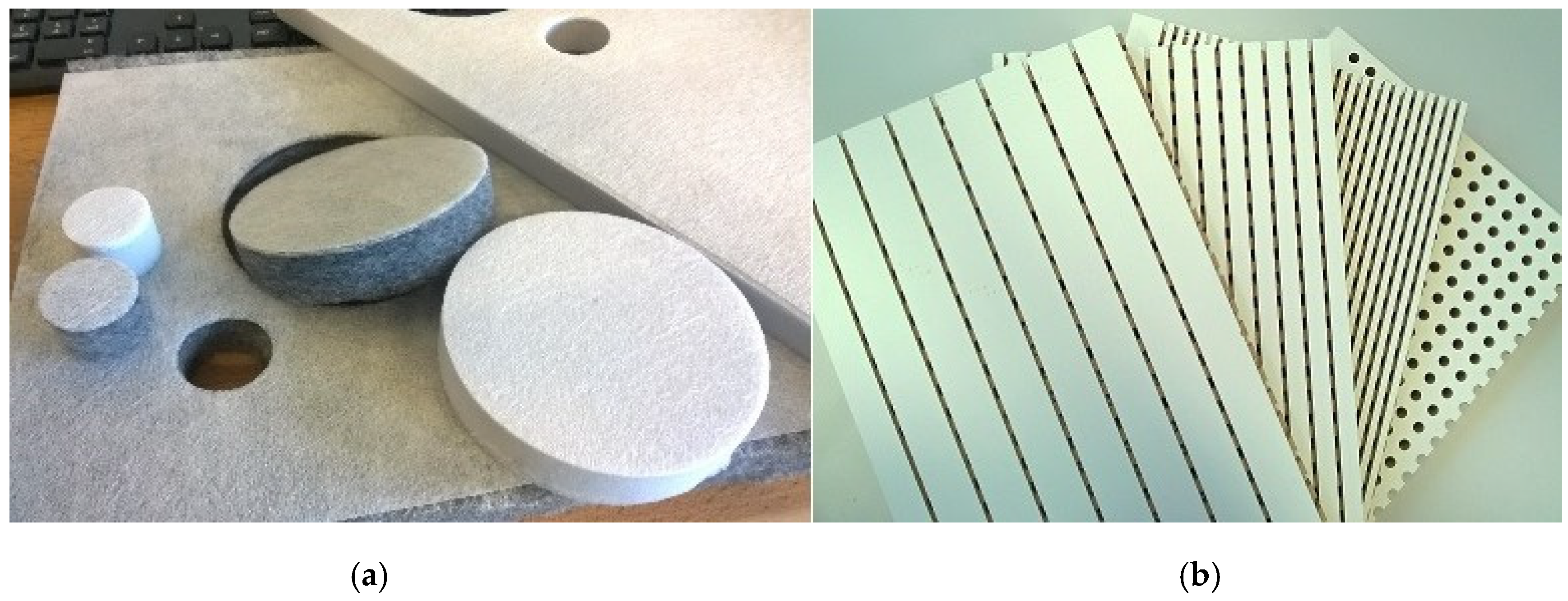
To manufacture the sound absorption composite materials to be studied, different sets of acoustic melamine foam (Cellofoam HR 290/0), a standard polyester (PES) nonwoven textile (Cellofoam F800FR HO), and commercial perforated panel resonators were chosen as porous bulk materials (see
Figure 1). The perforated panels were designed to be used with a backing air space to act as distributed Helmholtz resonators. The core of the panels was made of homogenous medium-density fiberboard (MDF) fabricated without resin binder (formaldehyde), so they were more environmentally friendly than other chemically-bonded panels. The thickness of the panels was 16 mm, with a density of 700–800 kg/m
3. The nominal thicknesses of the melamine foams were 10 and 20 mm and for the PES textile materials were 10, 20, and 50 mm. In practice, the PES samples exhibited measured thicknesses values of 8–9, 18–20, and 46 mm due to their unevenness.
Lamination of the thin nanofibrous membrane to these bulk materials was carried out using different adhesives. Melamine foam and PES were treated using a polymeric adhesive web (CoPAD, 8 gsm by Protechnic®), while a dispersive adhesive (Unimelt A417 by Stachema) was employed for the MDF panels.
A needleless electrospinning method using a cord (NanospiderTM, NS 1WS500U) was employed to manufacture the nanofibrous membranes. The liquid polymeric material was fed to a moving stainless-steel wire (cord). The wire electrode was connected to a high-voltage source and, on the top, there was a grounded counter-electrode. When the applied voltage exceeded a critical value, Taylor cones appeared on the wire surface (with orientation towards the counter-electrode). Polymer solution jets moved toward the collector, and nanofibrous layers were collected on a moving substrate after solvent evaporation. Optimal process parameters, such as the speed of the carriage, distance between the electrodes, voltage, etc., were carefully applied during the process. Voltages of 50 and 60 kV, relative humidity of 30% and 40%, and a temperature of 22 °C were applied during the course of electrospinning for PA6 and PVA, respectively. The resultant surface densities of the manufactured nanofibrous PA6 membranes were 0.2 ± 0.03 and 1 ± 0.02 gsm. The corresponding values for the PVA membranes were 0.6 ± 0.03 and 1 ± 0.02 gsm.
Characterization of the Materials
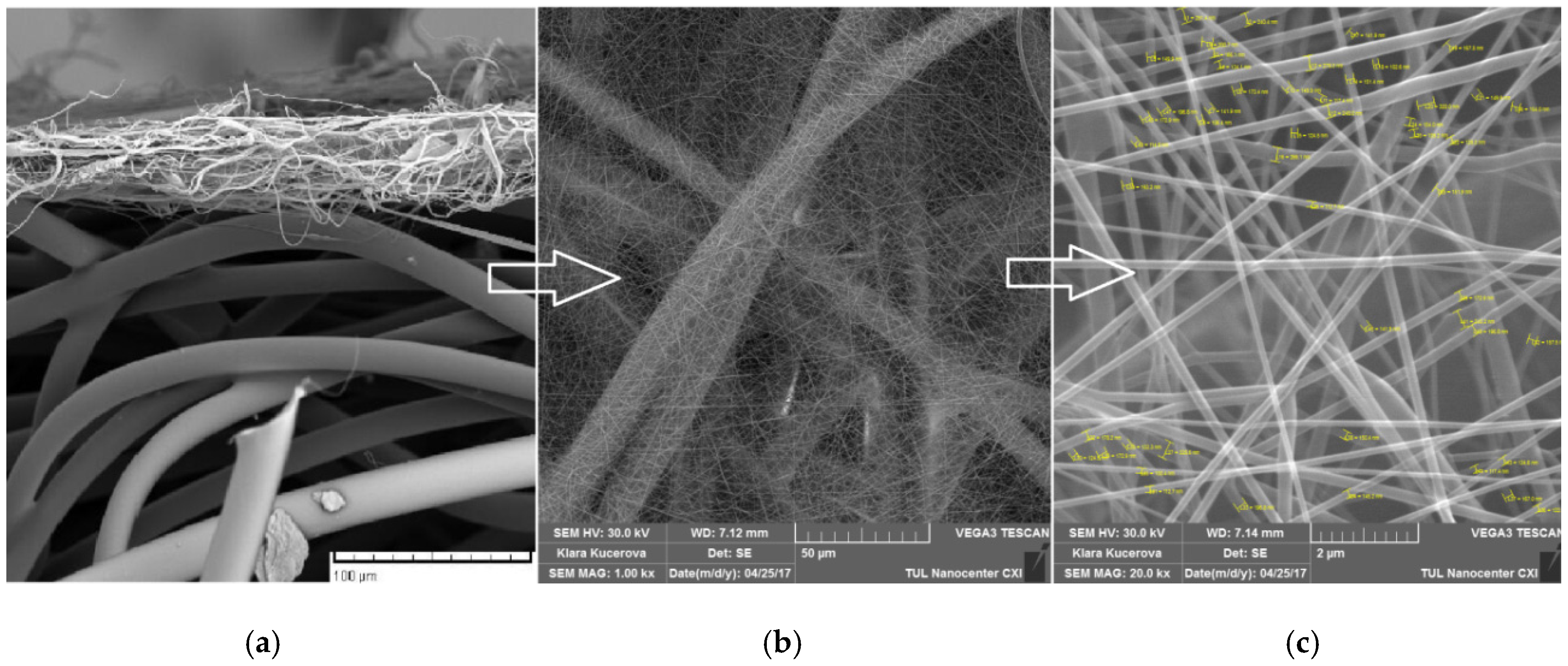
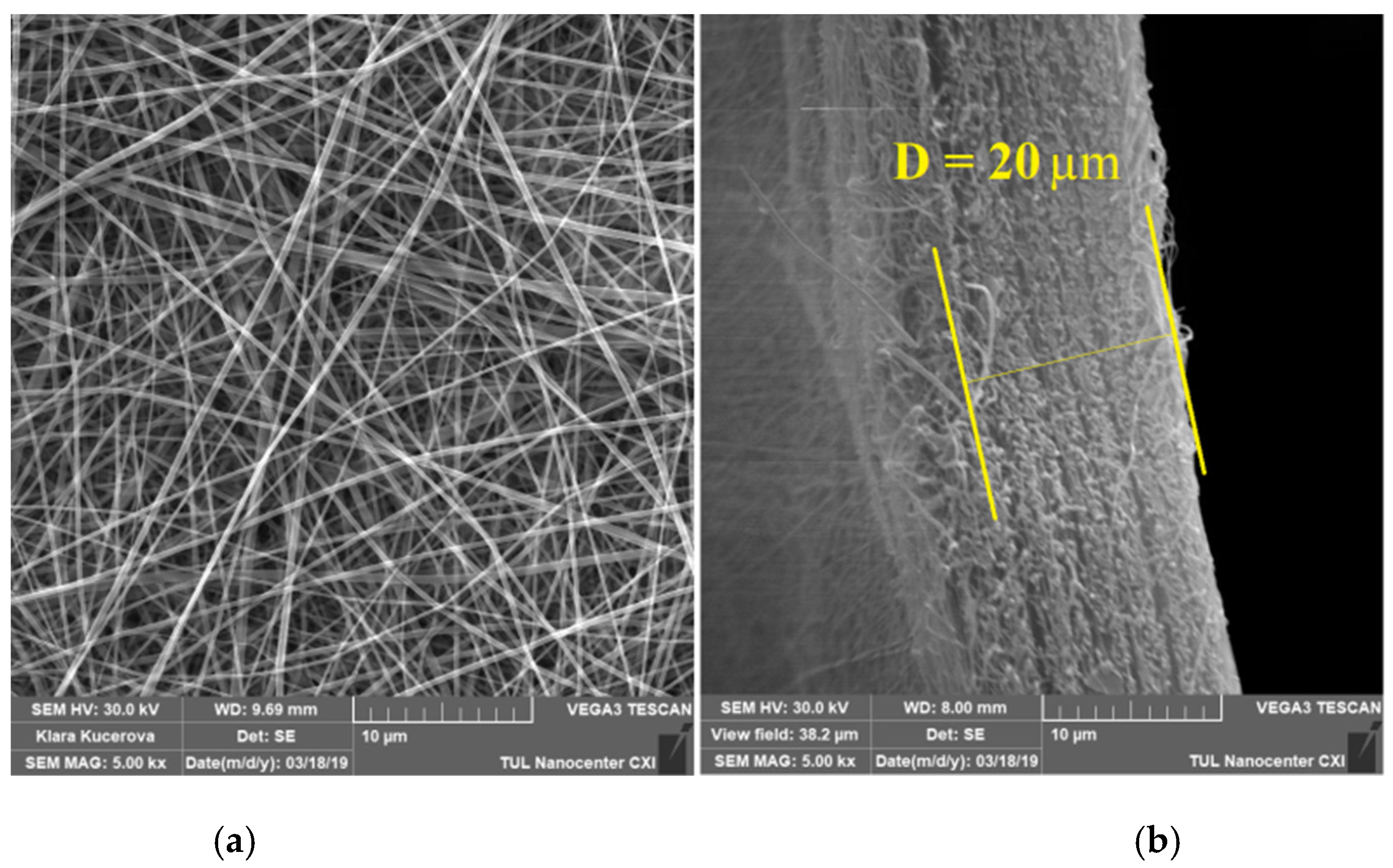
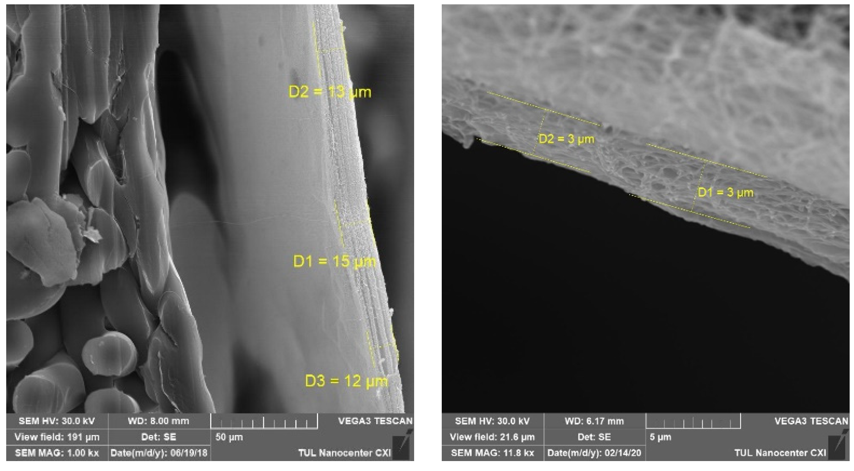
Both the fiber morphology and the fiber diameter of the electrospun manufactured nanofibers were determined using scanning electron microscopy (SEM). Moreover, to get information about the membrane thickness, a common approach was performed using liquid nitrogen specimen immersion followed by cutting (freeze fracture). Small sections of the nanofiber samples were placed on the SEM sample holder and sputter-coated with gold prior to SEM observation (Quorum Q150R Rotary-Pumped Sputter Coater). Micrograph images of the samples were obtained using a scanning electron microscope (TESCAN VEGA3) operated at an accelerating voltage of 1.48 kV.
The average fiber diameter was estimated from the SEM images using imaging analysis software (NIS Elements BR 3.2 by Nikon Instruments Inc.). More than 50 fibers were counted from two SEM images, which were taken of different places in each sample at 20k magnification value.
The airflow resistivity (
σ) of each sample was measured according to the standard ISO 9053 [
33], which basically describes the requirements for the direct measurement of the pressure developed across a sample for a known volume velocity of steady, slow airflow (i.e., laminar flow) passing through it. Each membrane specimen was stretched in a flow resistivity tube that carried a slow (1.5 mm/s) direct airflow, and the pressure drop across it was measured. Care was taken to prevent air leakage by ensuring a proper seal between the flow resistivity tube and the sample holder. All measurements were repeated five times in at least two specimens. In addition, five samples obtained from each of the two variants of PA6 nanofibrous membrane (0.2 and 1 gsm) were sent to the laboratories of Mecanum Inc. (Sherbrooke, Canada) in order to receive independent results.
Air-permeability (Q) was measured according to the standard ISO 9237 [
34] using an air permeability tester (M021A, SDL Atlas). The air-permeability values of the fibrous materials considered in this research were determined on the principle of drawing air through a 20 cm
2 area of material. The rate of airflow was adjusted until a 150 Pa pressure difference between the face and back sample surfaces was achieved. Then, the airflow was measured, and the air-permeability was calculated. Each sample was measured in at least five different places and, if the values varied considerably, in 10 places.
The membranes’ pore size was estimated from at least three measurements following the “bubble point method” principle, as described in the ASTM D6767 standard [
35]. The method is governed by the Washburn equation, here extended by the shape factor variable s, which eventually gives the pressure needed for a fluid wetting sample to be displaced by another through a capillary as:
where Δ
p is the applied pressure,
dp is the pore (capillary) diameter,
γ is the surface tension of the liquid–liquid or air–liquid interface, and
θ is the wetting angle with the solid matrix of the membrane. Using this method, the maximum pore size present in the pore distribution was determined, corresponding to the minimum pressure necessary to blow the first observed air bubble. The mean and the minimum pores were then received from the so-called “dry curves” as the stepped pressure was applied on a non-wetted sample. The flow rates at particular pressures were compared to the flow rates at corresponding pressures in a dry run, carried out after all the wetting fluid had been expelled in the initial run. In the course of this study, a capillary flow porometer (3G Micro by Quantachrome Instruments) with the proprietary wetting fluid Porofil (
γ = 16 mN/m) was employed.
The porosity (
ϕ) of the investigated nanofibers was determined both numerically and experimentally. A simple numerical estimation can be carried out using the formula expressing porosity as a function of specimen thickness (
d), its mass per unit area (
M), and material density (
ρf) via a solidity parameter. Solidity,
χ (also referred to as packing density), is the volume of solid material in a unit volume of the medium. It could also be expressed as the volume fraction of the solids in the medium [
36]. In our case, solids can include fibers, resins, additives, etc. From that, we can estimate the porosity as the three-dimensional volume void fraction of the specimen from the equation [
36]:
In addition, porosity was estimated experimentally during the pore size measurements by immersing specimens in the Porofil wetting fluid, determining their weights, and calculating porosity from the known densities and specimen dimensions.
Furthermore, considering the Brunauer–Emmett–Teller (BET) theory [
37], the assumed specific surface area can be determined from the nanofibrous diameter (
df) using the equation [
37]:
Surface area was also measured using a high-resolution gas sorption analyzer (Autosorb iQ-MP by Quantachrome Instruments). Krypton was employed as the gas. Specimen chamber degassing conditions were 60 °C, 60+ hours. The final correlation coefficients for all the outcome data were the same (0.9999). Surface area was measured from at least three samples (a maximum of five when it was necessary).
The normal incidence sound absorption coefficient was measured according to the standard ISO 10534-2 [
38] in the frequency range 50 to 6400 Hz using a two-microphone impedance measurement tube (Brüel & Kjær Type 4206). Some measurements were carried out in a larger tube with samples of 10 cm diameter only, so as to focus on the low frequency range, after previous calibration (Brüel & Kjær sound calibrator Type 4231). Care was taken to avoid leakages in the tube. Signal processing and analysis were performed by a multi-channel real-time signal analyzer (Aubion X.8) controlled by measuring software. This analyzer also served to generate a broadband random signal (pink noise), which was amplified by a power amplifier (Brüel & Kjær Type 2670 and Crown D-75A) and then fed to the tube loudspeaker. The analyzer measured the signals from the two microphones (Brüel & Kjær Type 4187), fast Fourier transformed the signals to the frequency domain, and thus calculated the frequency response function (FRF) H1 between the microphone channels. Later, the normal incidence sound absorption coefficient (
α) was determined from the estimated surface impedance of each sample according to the ISO standard. The results were plotted as a logarithmic function of the frequency.
3. Results and Discussion
Figure 2,
Figure 3 and
Figure 4 show some typical micrograph results.
Table 1 reports the results of the characterization of the manufactured nanofiber membranes.
The average airflow resistivity values measured independently by the Mecanum Inc. laboratory reported 9.80 ± 0.34 x 10
7 Pa s/m
2 for the 1 gsm PA6 and 2.02 ± 0.9 x 10
7 Pa s/m
2 for the 0.2 gsm PA6. Comparing these independent measurements with the airflow resistivity values shown in
Table 1, we observe that both results are within the same order of magnitude. The results for the 1 gsm PA6 membrane compare much better than the results for the lighter 0.2 gsm PA6 membrane.
It has been shown [
40] that it is difficult to mathematically relate the measured specific airflow resistivity of textiles and their air permeability in accordance with ISO 9237 and ISO 9053. However, we see that an increase in air permeability corresponds to a decrease in resistivity for each material studied.
Although the fiber web morphology of the nanofibrous membrane has been simplified as a pore-like structure, the calculated values of porosity are in good agreement with those measured. These values can be considered as quite high, mostly situated above the approximate value of 95%. It is interesting to compare these values of porosity with those obtained from the Kozeny–Carman model [
39]. This model can be derived from the Poiseuille’s equation for laminar flow of fluid, and it states that the airflow resistivity of a random network of fibers can be estimated as:
where
η is the dynamic viscosity of air (18.27 × 10
−6 Ns/m
2). Substituting the values of airflow resistivity and mean fiber diameter in Equation (4) and solving the cubic equation for porosity, we obtain the results that are included in the last row of
Table 1. We also observe good agreement between the results estimated by Equation (4) and those calculated by Equation (2) and the measured values of porosity.
In addition, we can see good agreement between the calculated and measured values of the average specific surface area, although we recognize a high dispersion of the values relative to the mean. This fact may be explained by standard electrospinning being a process with highly stochastic results in terms of fiber web geometry and alignment. In addition, electrospun fibrous layers are anisotropic, with a significant factor of local non-homogeneities.
To study the effects on sound absorption of adding the nanofibrous membrane to the bulk porous materials, the lightest nanofiber membranes have been considered in the following.
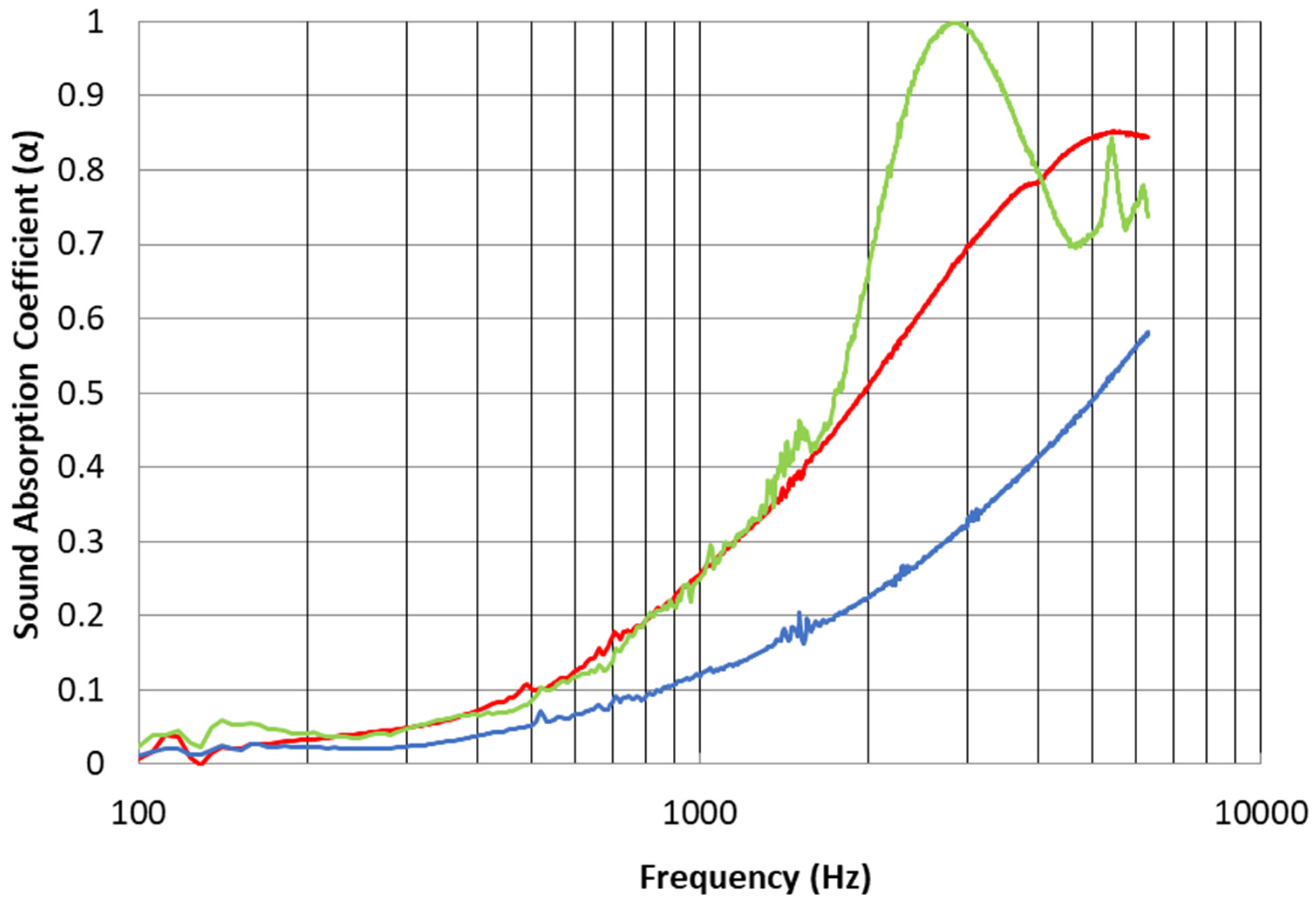
Figure 5 shows the normal incidence sound absorption coefficient as a function of frequency for the hard-backed bulk 8 mm thick PES nonwoven textile (Cellofoam F800FR HO) alone, for textile with the micro-fibrous substrate and for the textile coated with the PA6 nanofibrous membrane with an area density of 0.2 gsm. It can be noticed that the sound absorption performances of the bulk material with and without the micro-fibrous substrate are similar, where the bulk material with the substrate exhibits a slight improvement in high frequencies. This is obvious given the high air permeability of the nonwoven textile substrate. However, the effect of incorporating the nanofibrous membrane on the sound absorption properties is remarkable. This effect can be explained by the increase in the real part of the surface impedance of the bulk material when the nanofibrous membrane is attached on top of it. This added resistance is approximately given by the airflow resistivity of the membrane multiplied by its thickness, as explained by Chevillotte [
41]. Thus, in this case, the membrane adds approximately 16 Ns/m
3 to the system. A significant increase in the sound absorption coefficients is clearly observed for frequencies above 1000 Hz when the nanofibrous membrane is added to the fibrous bulk material with the micro-fibrous substrate. A maximum sound absorption value, near unity, is achieved at around 3000 Hz.
Sound absorption curves for the PES nonwoven textile (Cellofoam F800FR HO) are also shown in
Figure 6. Here, the measured results for the bulk material with three different thicknesses (8, 18 and 46 mm) are compared with the inclusion of the nanofibrous membrane with an area density of just 0.2 gsm on the fibrous bulk material (8 mm) with the micro-fibrous substrate. As expected, the bulk material exhibits better sound absorption when its thickness is increased, in particular for high frequencies. However, the effect of the nanofiber membrane on the 8 mm thick bulk material is appreciable. An increase of 100% in the sound absorption coefficient at the frequency of 3000 Hz is observed compared to the 18 mm thick bulk material. This could be of great importance to satisfy the interest in high levels of sound absorption with limited thickness. In addition, from
Figure 5 and
Figure 6, it can be seen that the effect of the micro-fibrous substrate on the sound absorption performance of the bulk material is unimportant when compared with the effect produced by an increase in its thickness. This is because the high air permeability of the substrate does not add significant airflow resistance to the composite.
Similar comments can be made for the melamine foam bulk material (Cellofoam HR 290/0).
Figure 7 shows the measured sound absorption for this bulk porous material with two different thicknesses (10 and 20 mm) and the bulk material coated with the substrate and the PA6 nanofibrous membrane of area density of 0.2 gsm. Sound absorption results are quite similar for the 20 mm thick foam alone and the 10 mm thick foam treated with the nanofiber membrane up to around 1500 Hz. Higher sound absorption values for the treated 10 mm thick bulk material can be observed over the frequency range 1500 to 4000 Hz. This result is very promising, considering that the 20 mm thick foam is two times thicker and heavier than the treated material.
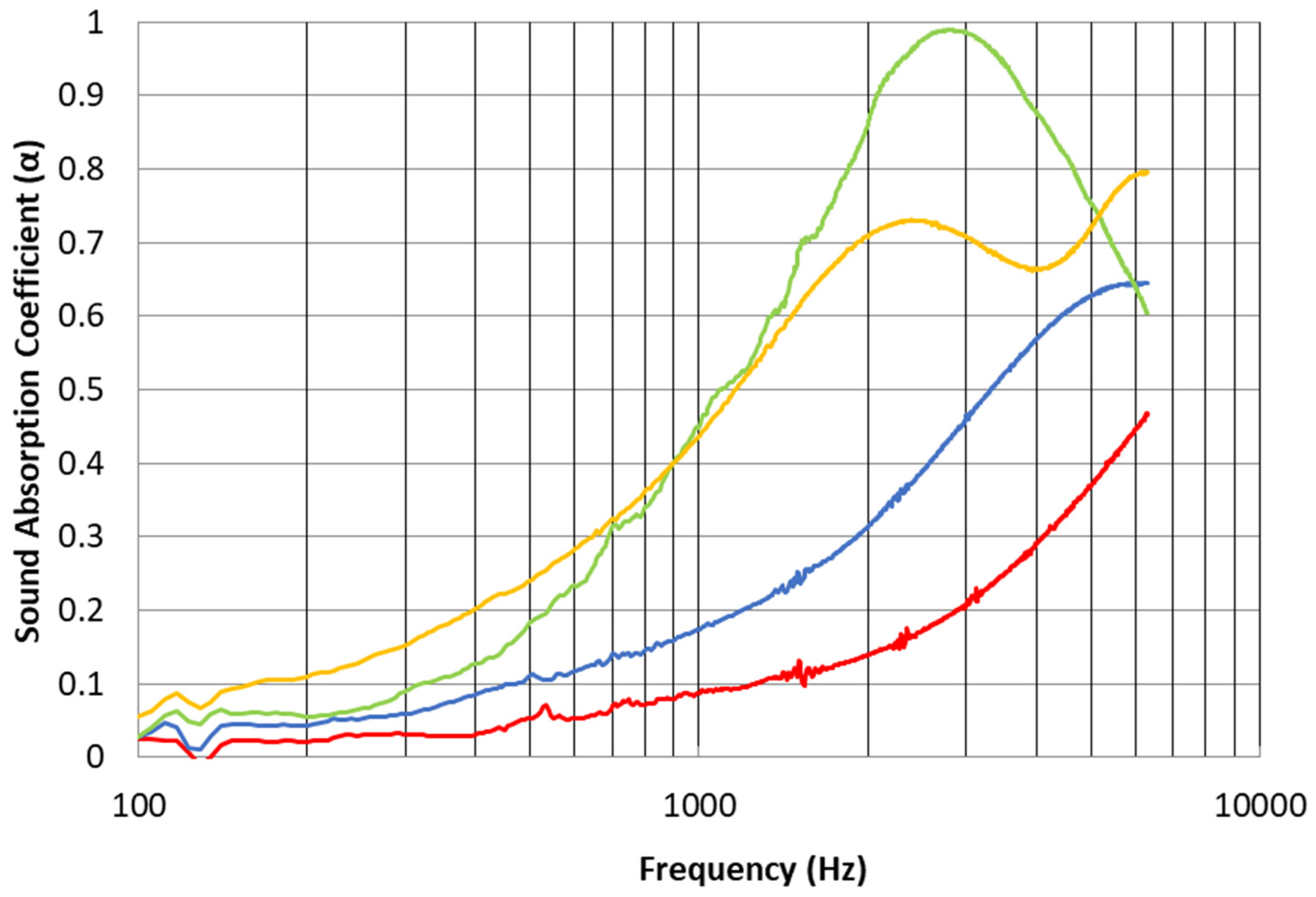
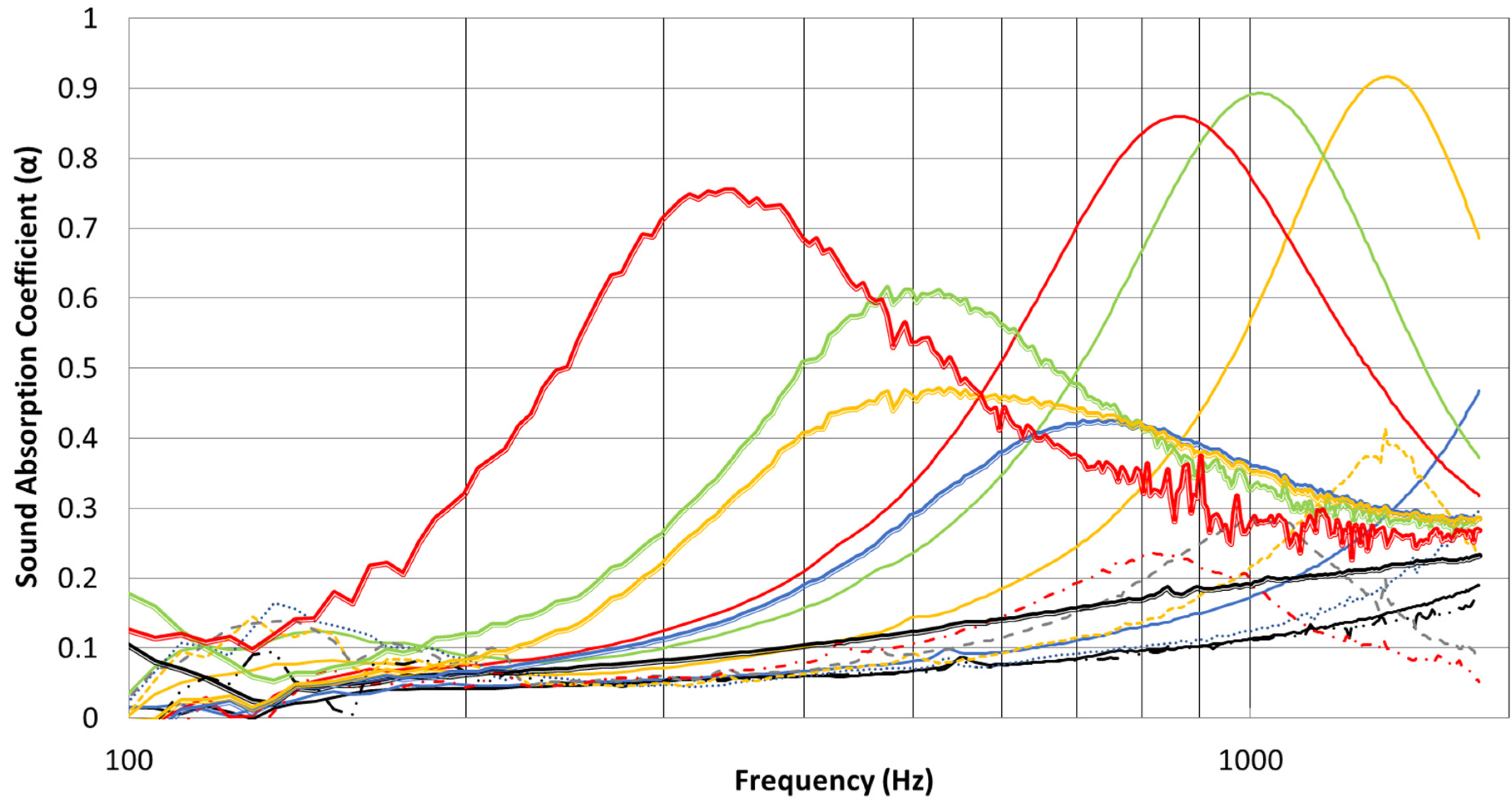
Figure 8 shows the comparison of the measured sound absorption of a perforated panel resonator alone (circular holes of radius 4 mm and evenly distributed in a grid with 16 mm between hole centers) and the panel treated with two different nanofibrous membranes (0.2 PA6 and 0.6 gsm PVA). The results were measured for different air backing spaces ranging between 0 and 34 mm. It can be seen that the resonance sound absorption peaks of the untreated panel are very low in the studied frequency range and the average sound absorption is not appreciable at low frequencies. For all cases, increasing the air gap distances resulted in leftward shifting of the sound absorption peaks. Inclusion of the nanofiber membrane produced a significant improvement in the low-frequency sound absorption performance of the perforated panel when the panel had an air backing space. A broad sound absorption peak is observed for the panel treated with both PA6 and PVA nanofibrous membranes. Moreover, the observed curves show that sound absorption curves tend to shift toward lower frequencies when the membrane area weight is increased. This result agrees with previous observations made by Kalinova [
9]. In this sense, the perforated panel treated with the 0.6 gsm PVA nanofibrous membrane absorbs more than 70% of sound energy at 300–400 Hz with an air-backing space of just 34 mm.
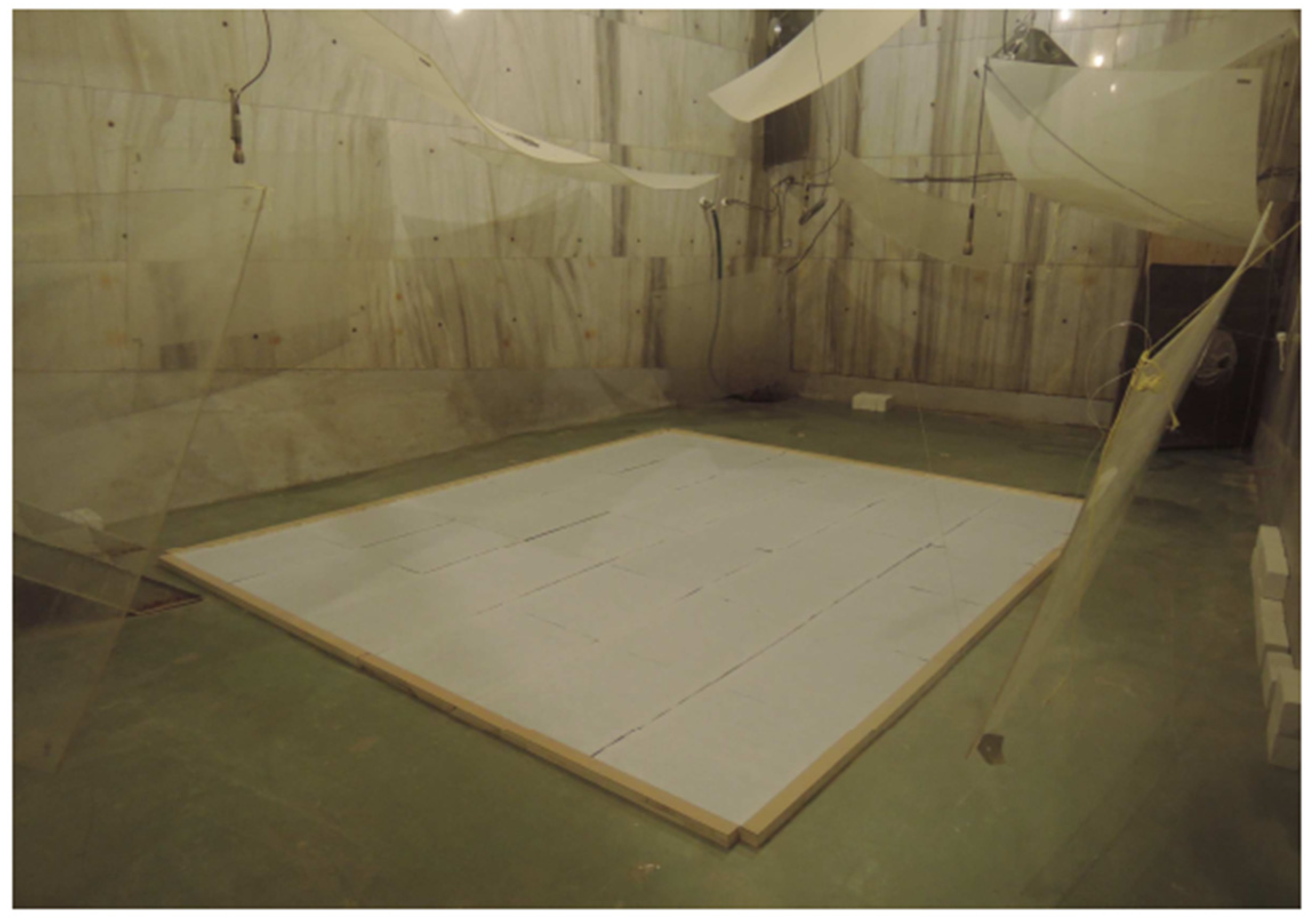
In light of the previous results, it is interesting to study the sound absorption performance in a standardized reverberation room. The values of normal incidence sound absorption measured with the impedance tube are useful for comparing the performance of small samples. However, in practice, the sound absorption of a material depends on the angle of sound incidence. Results of the sound absorption coefficients of materials tested in a reverberating room give a realistic estimate of the performance to be expected in practical applications. In this method, it is assumed that the intensities of the incident sound are uniformly distributed over all possible directions.
Intended samples of 10.8 m
2 were manufactured and sent to an independent laboratory (Aveton Ltd., Prague, CZ). There, the materials were tested in accordance with the ISO 354 standard [
42] to obtain the statistical sound absorption coefficients for one-third-octave frequency bands between 100 and 5000 Hz.
Figure 9 shows a photograph of one of the materials being tested in the reverberation room.
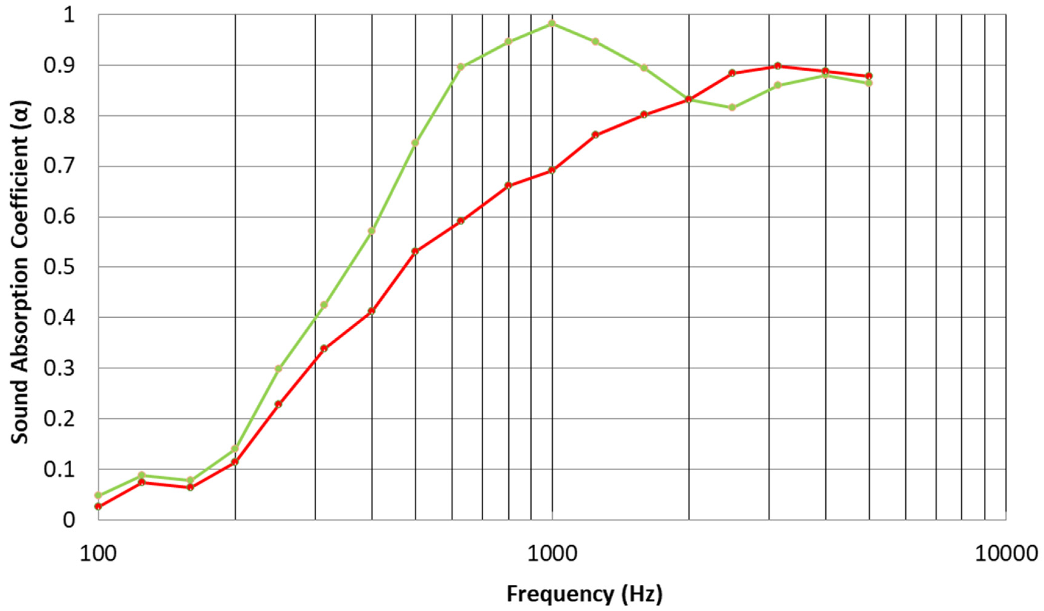
A comparison of the results between 20 mm thick melamine foam (Cellofoam HR 290/0) with a layer of micro-fibrous substrate and with the addition of a 0.2 gsm PA6 nanofibrous layer can be seen in
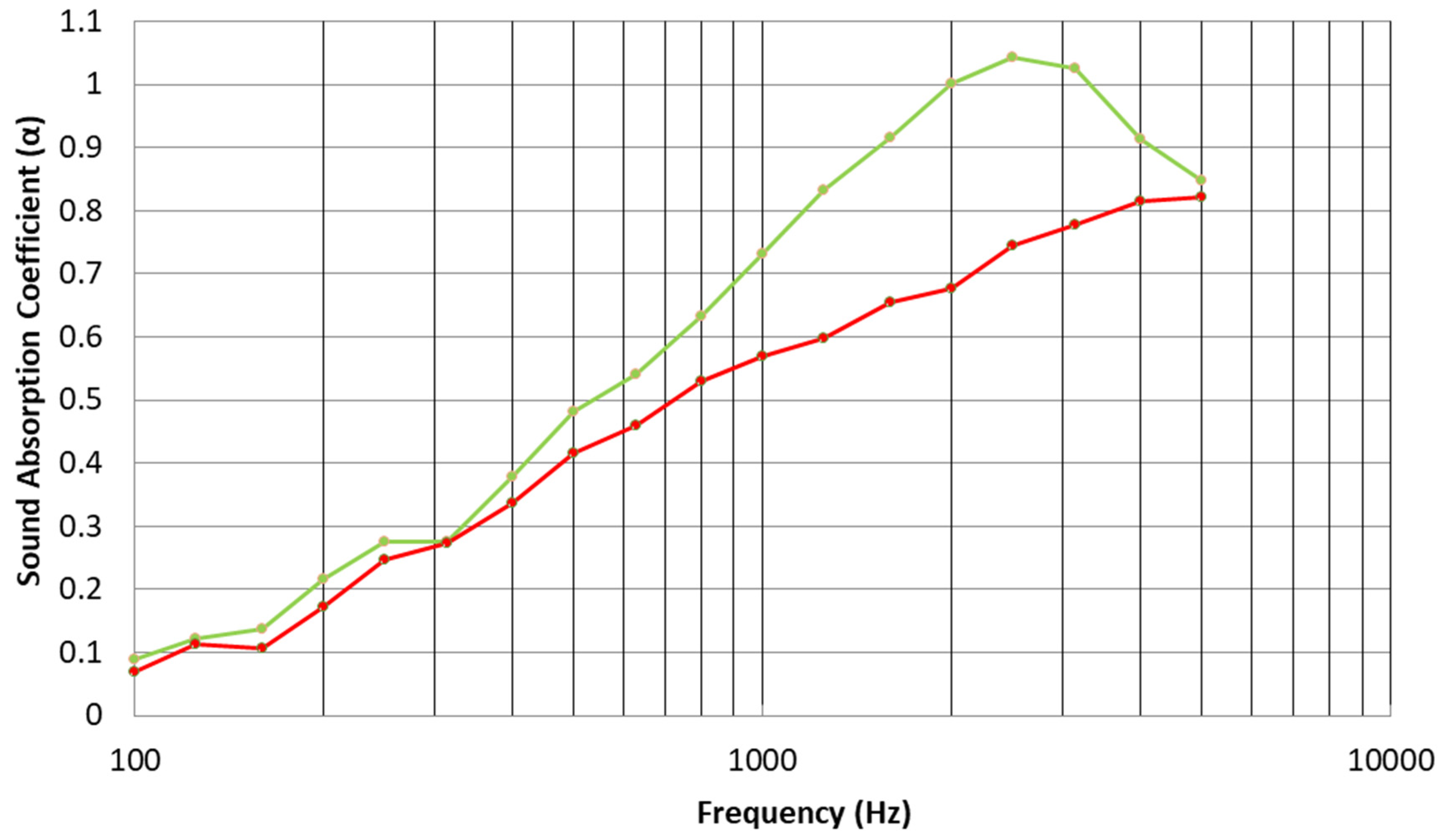
Figure 10. We observe a noticeable improvement in the sound absorption performance of the bulk material with the addition of the nanofibrous membrane between the bands centered at 300 and 2000 Hz. The maximum sound absorption of the treated material occurs at the frequency band centered at 1000 Hz, where the nanofibrous treatment increased the sound absorption coefficient of the bulk material by about 40%. Similar results are shown in
Figure 11 for an 18 mm thick PES nonwoven textile (Cellofoam F800FR HO) with the substrate treated and untreated with a 0.2 gsm PA6 nanofibrous layer. In this case, an improvement in the sound absorption is observed above 500 Hz, exhibiting the highest sound absorption coefficient at the band centered at 2500 Hz.
4. Conclusions
This paper has reported the standardized characterization of nanofibrous membranes used to coat three porous bulk acoustical materials to produce sustainable sound absorbers. The membranes were manufactured from two different polymers using the needleless electrospinning technique. This resulted in very thin membrane samples that had high porosity and very high airflow resistivity. The sound absorption coefficient results measured in an impedance tube show that a significant improvement in the sound absorption performance of the bulk materials can be achieved by incorporating the nanofibrous layer on them. The application of the membranes on the surface of a traditional air-backed perforated panel also improves the sound absorption, exhibiting a broad peak of sound absorption in the low-frequency range. This is particularly true when the membrane area weight is increased. The results of the diffuse-field sound absorption coefficient measured in a reverberation room also show a substantial increase in the sound absorption performance of bulk porous materials treated with nanofibrous membranes.
Interestingly, these high values of sound absorption were obtained after treating materials of low thickness. This is of great importance to satisfy the challenge in the transportation industry of high sound absorption values with reduced weight to reduce fuel consumption. Joost [
43] has reported that reducing a vehicle’s weight by 10% can improve the fuel economy of the vehicle by 6% to 8%. In a recent sustainable report [
44], airlines have estimated that losing just a pound (0.45 kg) in weight from every plane in their fleet would save 53000 liters of fuel a year. Thus, further application of these membranes to recycled bulk materials has the potential to result in more environmentally friendly acoustic materials.
Although this work has focused on experimental results, there is a clear need for theoretical work to predict the acoustical properties of nanofiber membranes. This would be useful to tailor the sound absorption characteristics of a material made of nanometric fiber to a particular problem. However, this is far from easy. Some authors [
16] have indicated that several problems make this difficult, such as the complexity of characterizing the non-acoustical properties and the high uncertainty when determining the geometric dimensions of such a tiny structure. In addition, Umnova et al. [
45] have described that when fiber radius and/or inter-fiber distances become comparable to a saturated gas molecular mean free path, conventional theoretical models have to be modified to allow for velocity and thermal slip. The mean free path is approximately equal to 60 nm for air in normal conditions. However, a theoretical approach to completely describe the acoustical properties of electrospun nanofiber membranes must also consider the complexity of their inner structure and fiber orientation, as well as accounting for membrane vibration.
Further work will be devoted to assessing the real environmental impact of the nanofibers studied in this research through a life cycle assessment (LCA) and cost/benefit analysis.


