Article

Structural Performance of Damaged Open-Web Type SRC Beam-Columns after Retrofitting

1
Research Center for Urban Safety and Security, Kobe University, Kobe 657-8501, Japan
2
Graduate School of Engineering, Kobe University, Kobe 657-8501, Japan
*
Author to whom correspondence should be addressed.
Sustainability 2020, 12(4), 1381; https://doi.org/10.3390/su12041381
Submission received: 12 December 2019 / Revised: 7 February 2020 / Accepted: 10 February 2020 / Published: 13 February 2020

Abstract

:
The structural performance of damaged open-web type of steel encased reinforced concrete (SRC) beam-columns after retrofitting was experimentally investigated. The experimental parameters were the open-web type of the encased steel and the maximum tip displacement of the columns during the initial loading. First, each column was cyclically loaded to the targeted displacement. Subsequently, the test columns were retrofitted and reloaded. The damaged portions of each column were retrofitted with the polymer cement mortar, and the epoxy resin was injected into the cracks. The experimental results indicated that the measured stiffness of the retrofitted columns was lower than the initial ones, while the displacements experienced in each column were different. The lower stiffness might be attributed to deterioration of the concrete rigidity, low rigidity of the resin and imperfect injection of the resin. Numerical analyses were also conducted to evaluate the retrofitted column behavior. The effect of the strain hysteresis of concrete at the first loading was considered for the behavior at the second loading. The analytical results predicted the experimental behaviors fairly well, which implies the validity of the analytical methods presented in this paper for evaluating the structural performance of the retrofitted SRC columns.

1. Introduction

After a strong earthquake, many damaged buildings and infrastructures are demolished and reconstructed instead of being seismically retrofitted and reused because the structural or seismic performance of the damaged buildings and infrastructures after retrofitting was unclear, which makes it difficult to reliably and accurately evaluate to what extent the damaged components and structures could be recovered. To realize a sustainable society in an earthquake prone country like Japan, the development of retrofitting engineering is very important because if the damaged buildings and infrastructures were appropriately repaired and/or strengthened they could still have a sufficient resistant capacity against future strong earthquakes. Considering the fact that the greenhouse gas emitted from the construction industry accounts for a large percentage of the total national emissions in Japan [1], retrofitting the damaged building and infrastructures, and extending their serviceability life can contribute to reducing the carbon dioxide emissions and enhancing the sustainability of buildings and infrastructures, and of the society.
Repairing, retrofitting and strengthening of damaged reinforced concrete (RC) structures by using epoxy resin have been widely used and well-studied [2,3]. French et al. investigated the effectiveness of epoxy repair techniques for moderately damaged RC joints [4]. Myers et al. presented the durability performance of RC beams [5]. Balsamo et al. performed pseudo-dynamic tests of full-scale RC frame epoxy injected and strengthened by using carbon fiber reinforced plastic (CFRP), and discussed their seismic behavior [6]. However, there is little, if any, information on the retrofitting of steel-encased reinforced concrete (SRC) components by epoxy resin despite SRC structures being used widely in infrastructures and buildings throughout Japan since the 1960s.
Many open-web-type SRC beam-columns with batten plates were damaged by the Great Hanshin-Awaji Earthquake. Remarkably, the batten steel plates of open-web type SRC beam-columns that suffered considerable damage during the Kobe earthquake were mostly bolt-connected or rivet-connected ones [7]. To obtain fundamental information related to the seismic recovery of damaged SRC beam-columns, the structural performance of the damaged open-web type of SRC beam-columns after retrofitting was experimentally investigated in this study. As described herein, open-web type SRC beam-column specimens with weld-connected and bolt-connected batten steel plate encasements were fabricated and tested under combined constant axial and cyclic lateral loads. The experimental parameters were the open-web type of the steel encasement, the maximum tip displacement of the beam-columns in the initial loading and the axial load ratio.
The objectives of this paper are (1) to verify the effectiveness of retrofitting by epoxy resin in recovering the mechanical properties of damaged SRC columns, (2) to present experimental information on the structural performance of damaged open-web type SRC beam-columns and (3) to evaluate numerically the structural performance of the retrofitted beam-columns.

2. Experiment of Open-Web Type SRC Beam-Columns

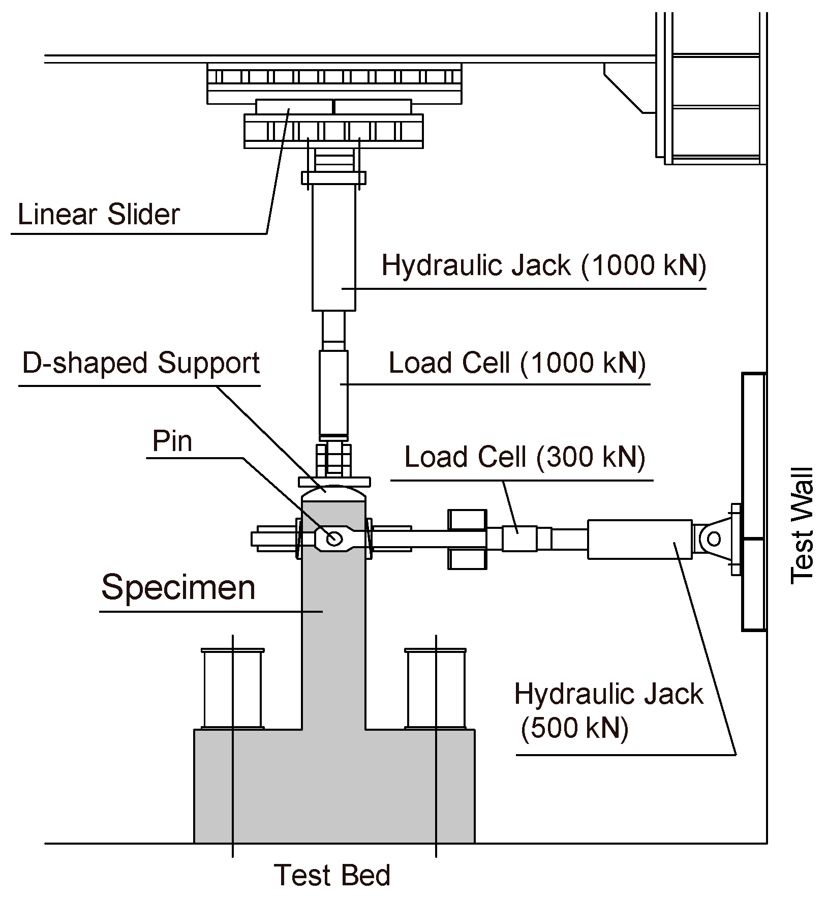
2.1. Outline of Experiment
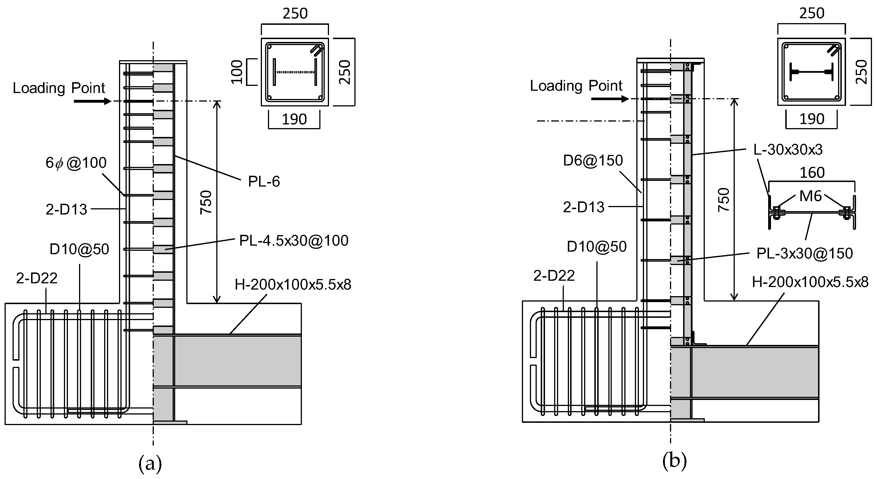
Test specimens were open-web type SRC beam-columns and their encasements were built with weld-connected or bolt-connected batten steel plates. Specimens were tested under a combined constant axial load and cyclic lateral load, using the loading apparatus shown in Figure 1. First, each beam-column was loaded cyclically to a targeted displacement. After the first loading, the specimens were retrofitted and reloaded. The damaged portions of each column were retrofitted with polymer cement mortar. Then, epoxy resin was injected into the cracks.

2.2. Specimen

Six specimens were fabricated and tested (see Figure 2). The section width and depth were 250 mm. Each specimen was fixed to the rigid test floor through a loading stub. The steel encasement was of the open-web type, and the depth of steel encasement was 160 mm. For weld-connected specimens (W Series), they were built with flange plates (100 × 6 mm) and batten steel plates (30 × 4.5 mm) with a spacing of 100 mm. For bolt-connected specimens (B Series), they were built with chord angles (L-30 × 30 × 3) and batten steel plates (30 × 3 mm), and were connected with bolts, with a batten plate spacing of 150 mm. The bolts were M6. The introduced torque was 15 kNm. The main reinforcements were D13 deformed bars welded to the upper end plate. The hoop was a 6 mm round bar for W Series, with spacing of 100 mm, and deformed bar D6 for the B Series, with a spacing of 150 mm.
The outlines of the specimens are listed in Table 1. The experimental parameters were the open-web type of steel encasement, the tip displacement of the columns at the initial loading and the axial load ratio. Three levels were set for the maximum tip displacement in each steel encasement type, namely: for weld-connected specimens, (1) displacement where the encased steel portion reached the yield strain for the first time, (2) displacement corresponding to the peak strength of a specimen and (3) displacement where the lateral load drops to the yield strength after the peak; for bolt-connected specimens, (1) displacement corresponding to the peak strength and (2) displacement where the lateral load drops to the yield strength after the peak.

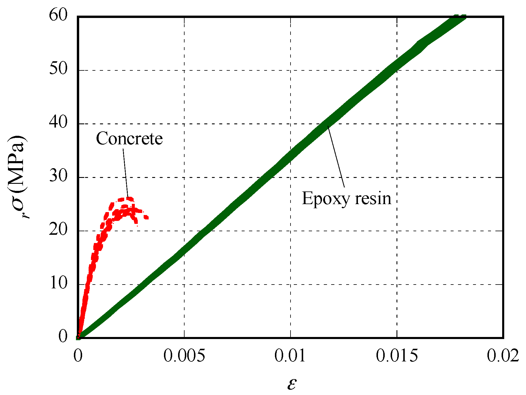
2.3. Material Propeties

Standard tensile and compressive tests were conducted for the steel, concrete, polymer cement mortar and epoxy resin, which were injected into the cracks of the damaged portions, to gain the mechanical properties of the materials used. The measured results are presented in Table 1, Table 2 and Table 3. Examples of the compressive stress–strain relations of epoxy resin are shown in Figure 3. It is apparent that the initial rigidity of the epoxy is about 0.1 times the rigidity of concrete. However, the epoxy resin remained almost elastic, until its compressive strength and the strength of epoxy were larger than 70 MPa. A splitting tensile test of epoxy resin was not performed for the B Series.

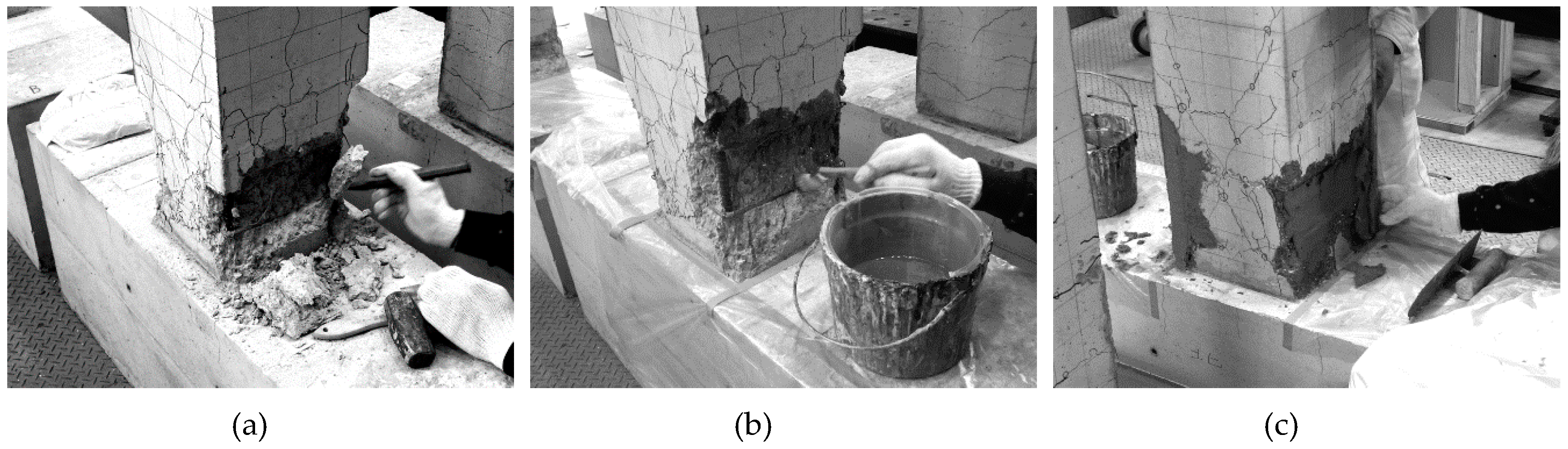
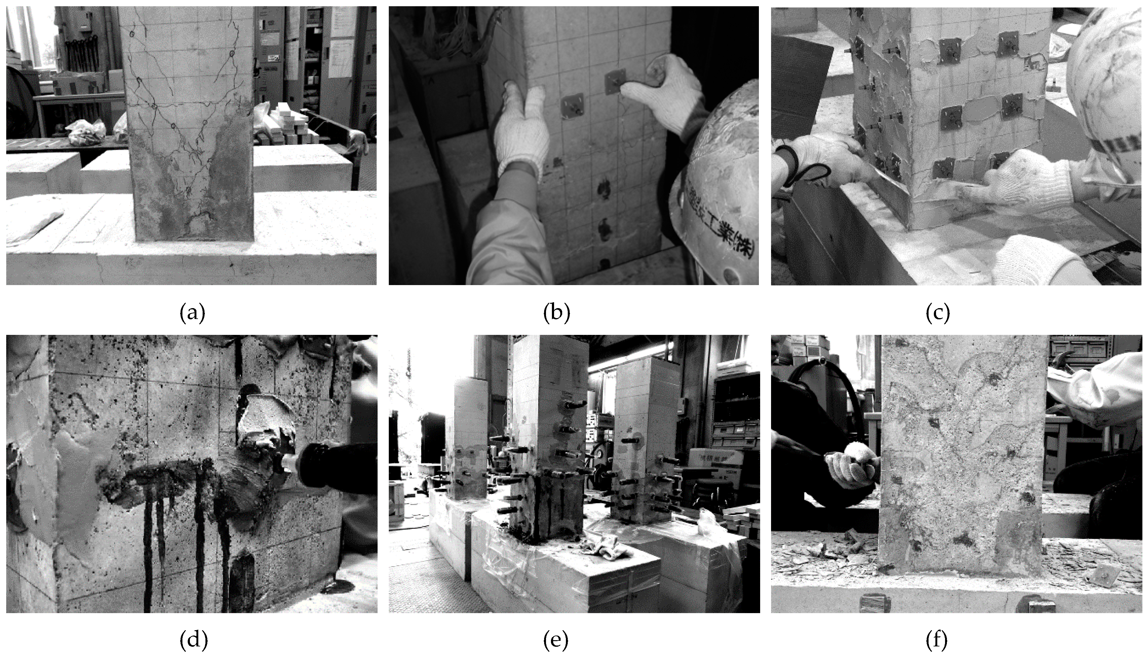
2.4. Method of Retrofitting

The main retrofitting method includes the injection of epoxy resin into the observed cracks. The cross sections were rebuilt using polymer cement mortar (see Figure 4) before injecting the epoxy resin, because the damage was heavy and the cover concrete was partially spalled off. After removing the fragile portion of concrete, the primary resin was coated onto the surface to improve the adhesiveness with the existing concrete. Then, the section was rebuilt with polymer cement mortar and cured for four weeks.
The injection of the epoxy resin into the cracks was conducted using the internal pressure of the rubber tube swollen by resin for injection. After removing the surface dust, the rubber tube attachments were put on the cracks with a large width or the point where two cracks were crossed. The other cracked portions were caulked. Then, the rubber tubes were set and epoxy resin was injected. The surface was ground after the resin hardened. The procedure of the epoxy resin injection to the crack is depicted in Figure 5.

3. Experimental Results

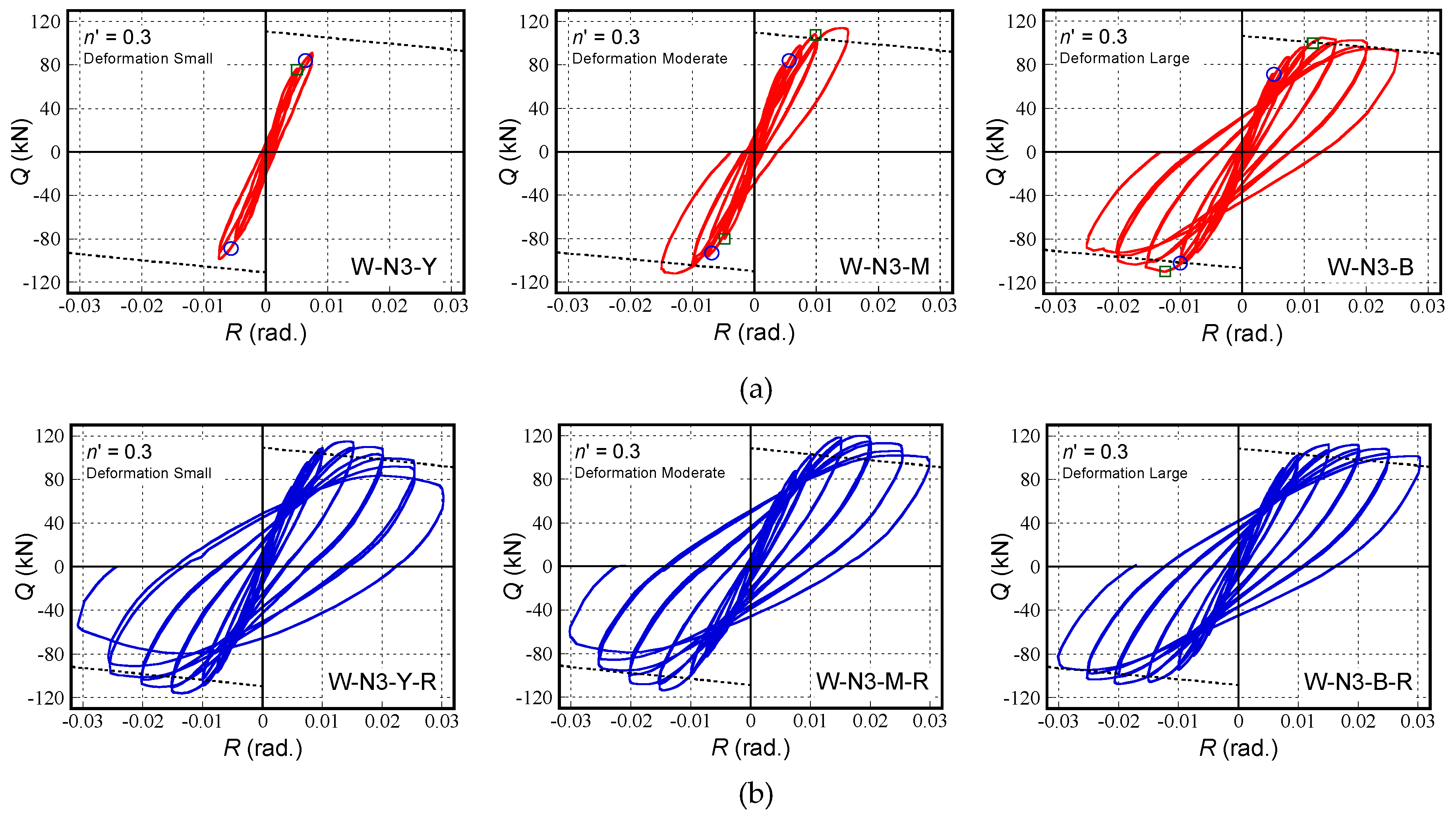
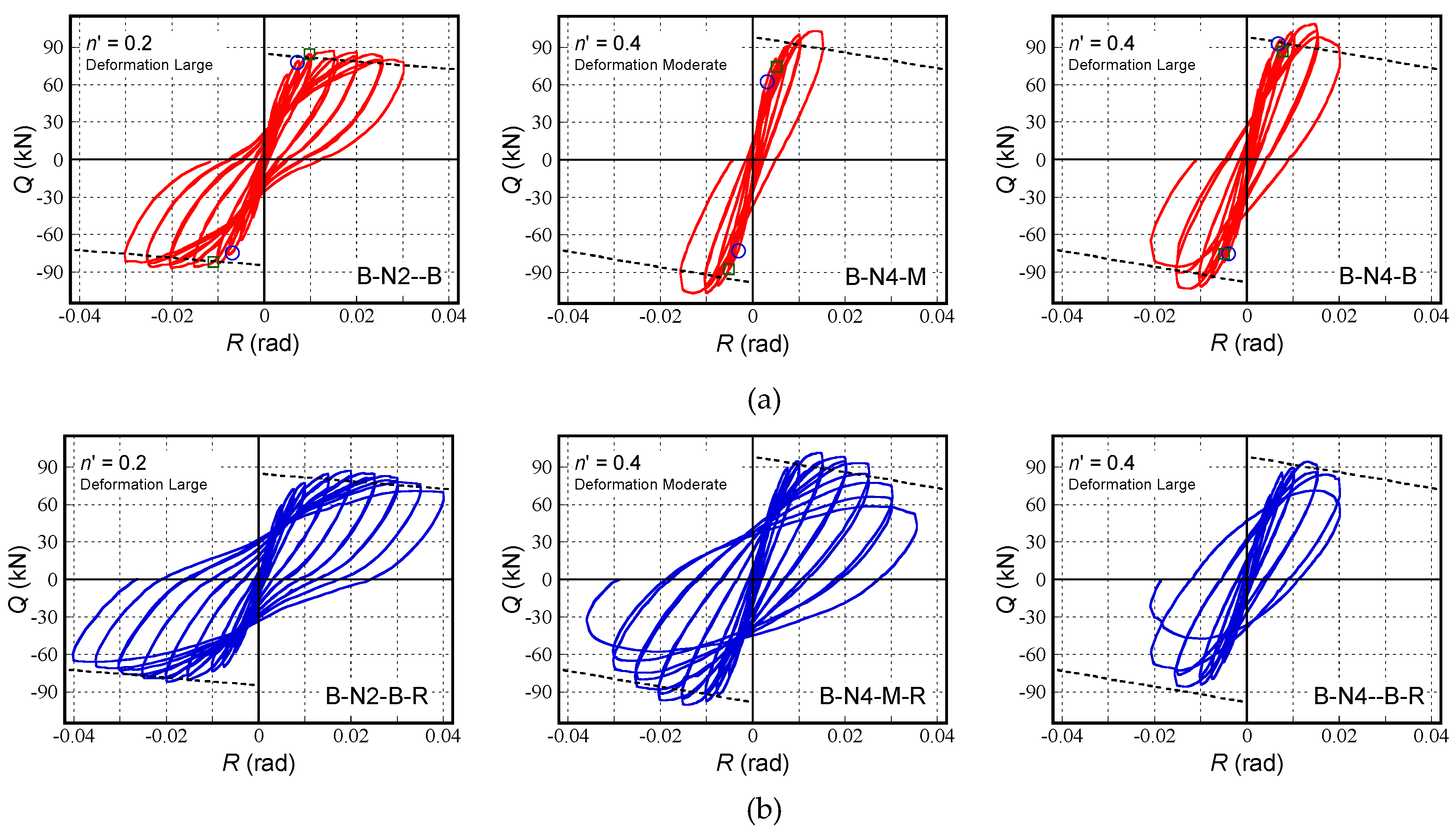
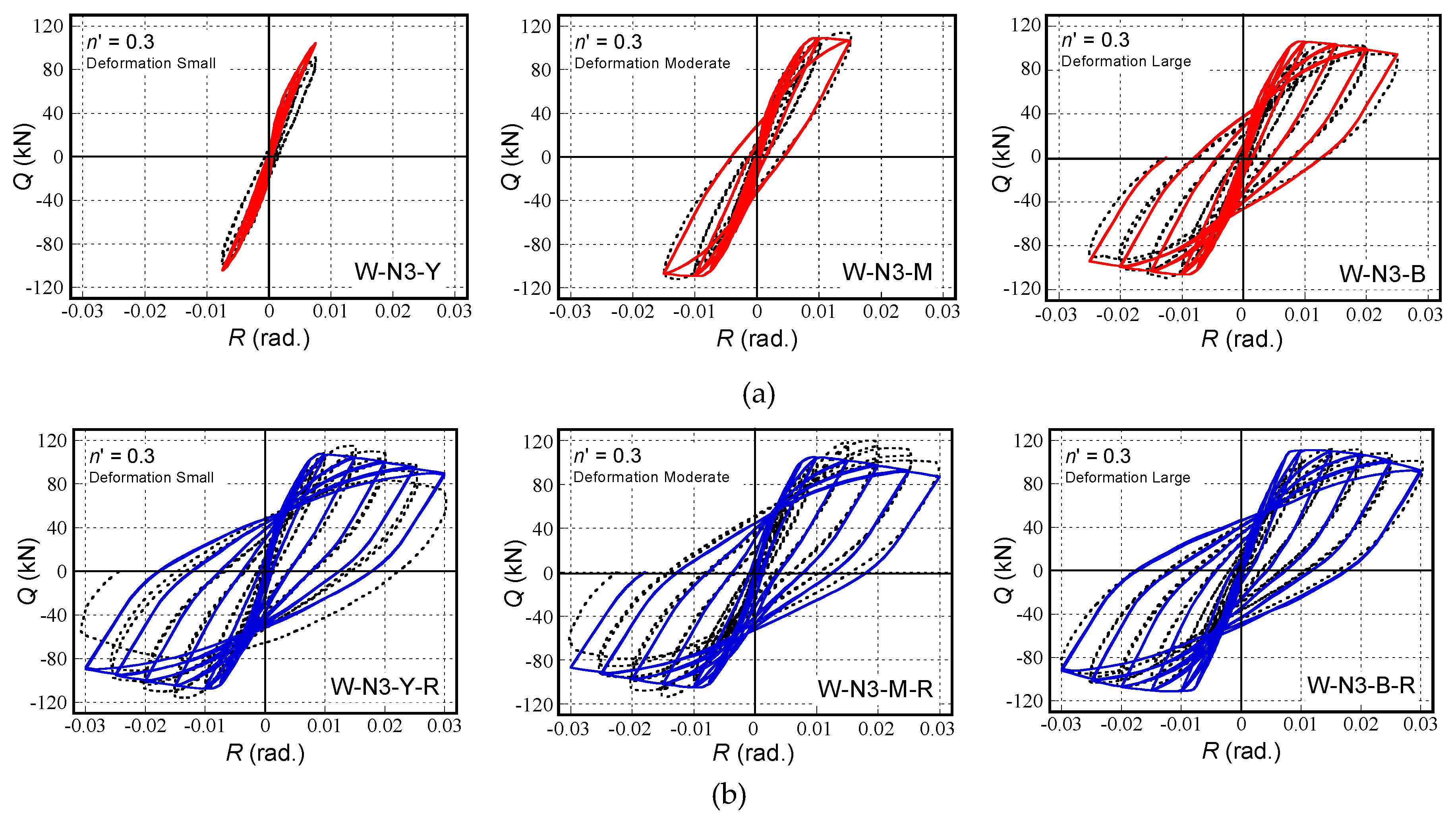
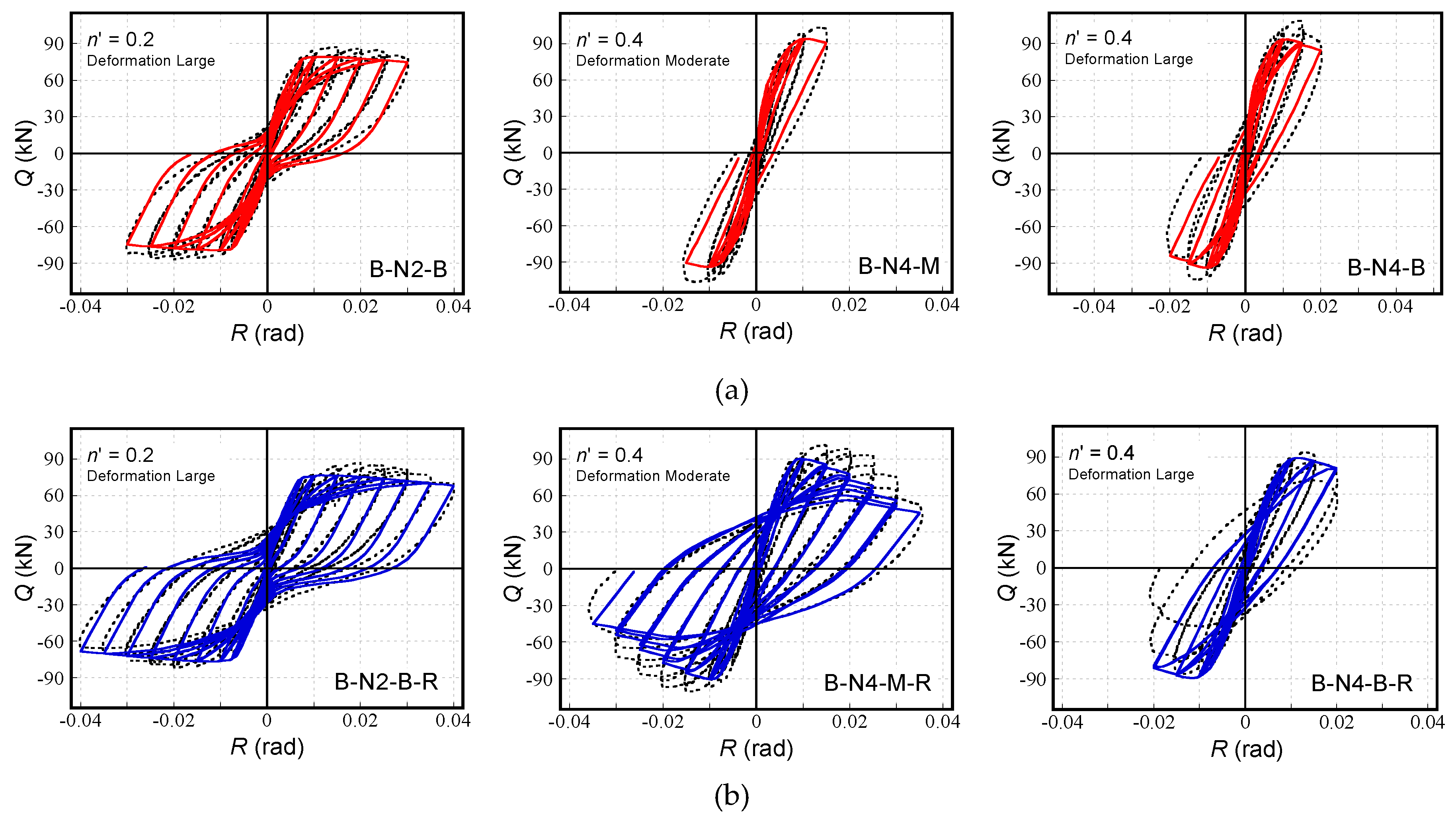
3.1. Horizontal Load–Drift Ratio Relation

Figure 6 and Figure 7 portray the horizontal load–drift ratio relations. The measured behaviors are shown as red and blue solid lines. Blue circles show the points at which the main reinforcement began yielding. Green squares show the points at which the steel portion began yielding. The dotted line is the mechanism line, as obtained by assuming that a plastic hinge is formed at the bottom of the beam-column. Table 4 shows the primary experimental results.
From these figures and tables, it is apparent that the initial stiffness of the retrofitted columns was lower than that of the initial columns, although the displacements experienced in each column differed. The stiffness of the retrofitted column decreased as the displacement in the first loading became larger. The lower stiffness might be attributed to the deterioration of the concrete rigidity, the low rigidity of the resin and the polymer cement mortar and the imperfect injection of the resin.
The experimental results also showed that the column that experienced the larger displacement and higher axial load (Specimen B-N4-B-R) showed a little lower load carrying capacity, but the others showed approximately the same capacities as those of the initial columns in the case of the bolt-connected specimens. In the case of the weld-connected specimens, all of the retrofitted columns showed a higher load-bearing capacity, even though the experienced displacements in each column differed. The lower load carrying capacity of the specimen B-N4-B-R was due to the buckling of the longitudinal reinforcements. The higher load carrying capacities of the weld-connected specimens can be attributed to the effect of the strain aging and strain hardening of the steels.

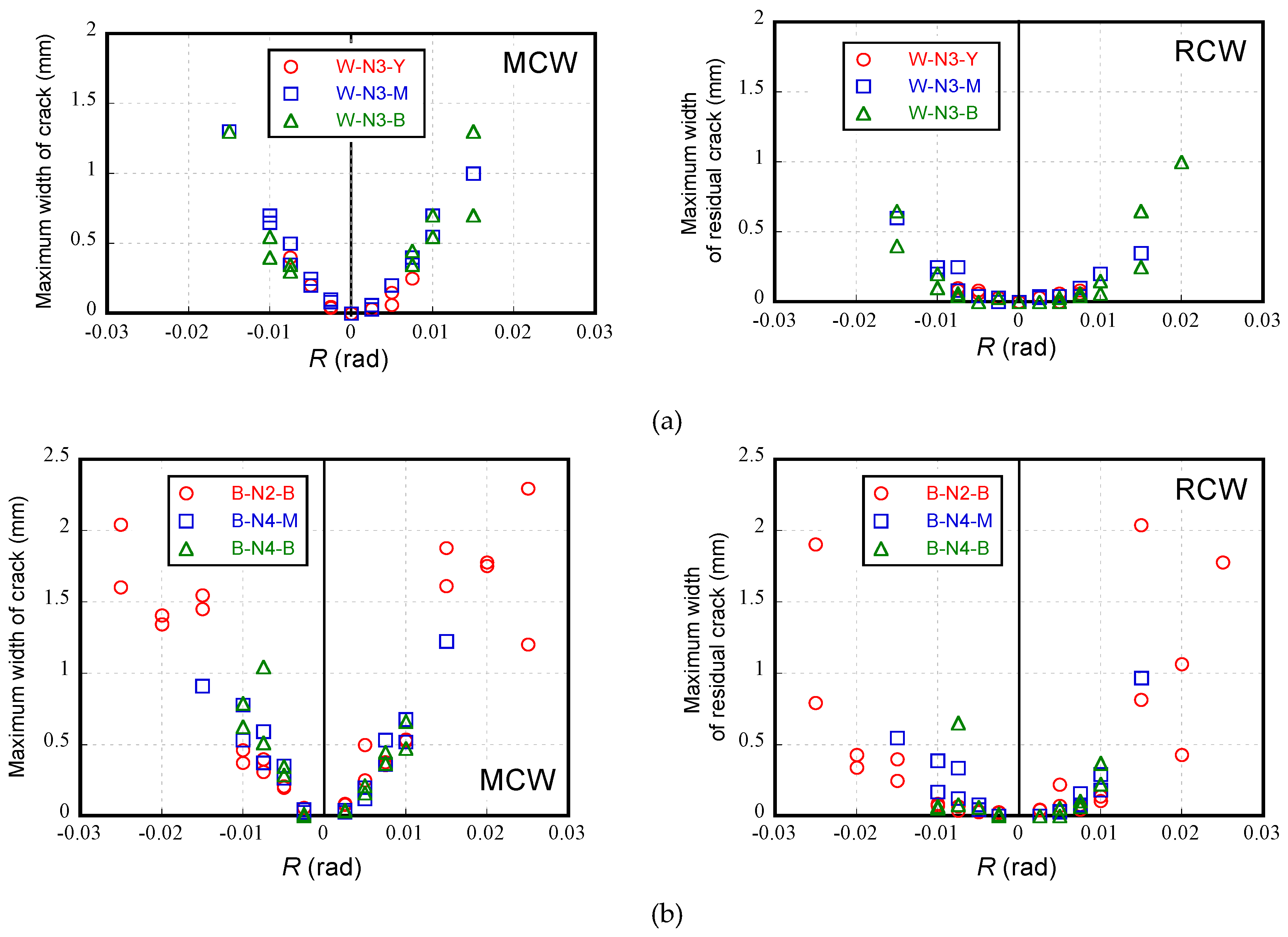
3.2. Width of Flexural Cracks

Flexural crack widths were measured to elucidate the relationship between the measured crack width and the drift ratio. This kind of relationship is valuable for predicting or assessing the degree of damage to the SRC components after being hit by a strong earthquake by measuring the widths of the residual flexural cracks. Figure 8 shows the experimental maximum crack width (MCW) measured at each peak drift ratio, as well as the residual crack width (RCW) measured after unloading from each peak drift.
It is apparent from Figure 8 that the relations between the MCW and drift ratio could be approximated as a linear relation. However, the relations between the RCW and drift ratio exhibited a linear behavior until the drift ratio of 0.01 rad, where the yielding of encased steels commenced, and then abruptly increased along with drift ratio from 0.01 rad onward. These relations, in particular, the relation between RCW and drift ratio, can be used to estimate the maximum drift ratio an SRC component may experience during an earthquake and the maximum crack width that may occur.

4. Evaluation of Structural Performance

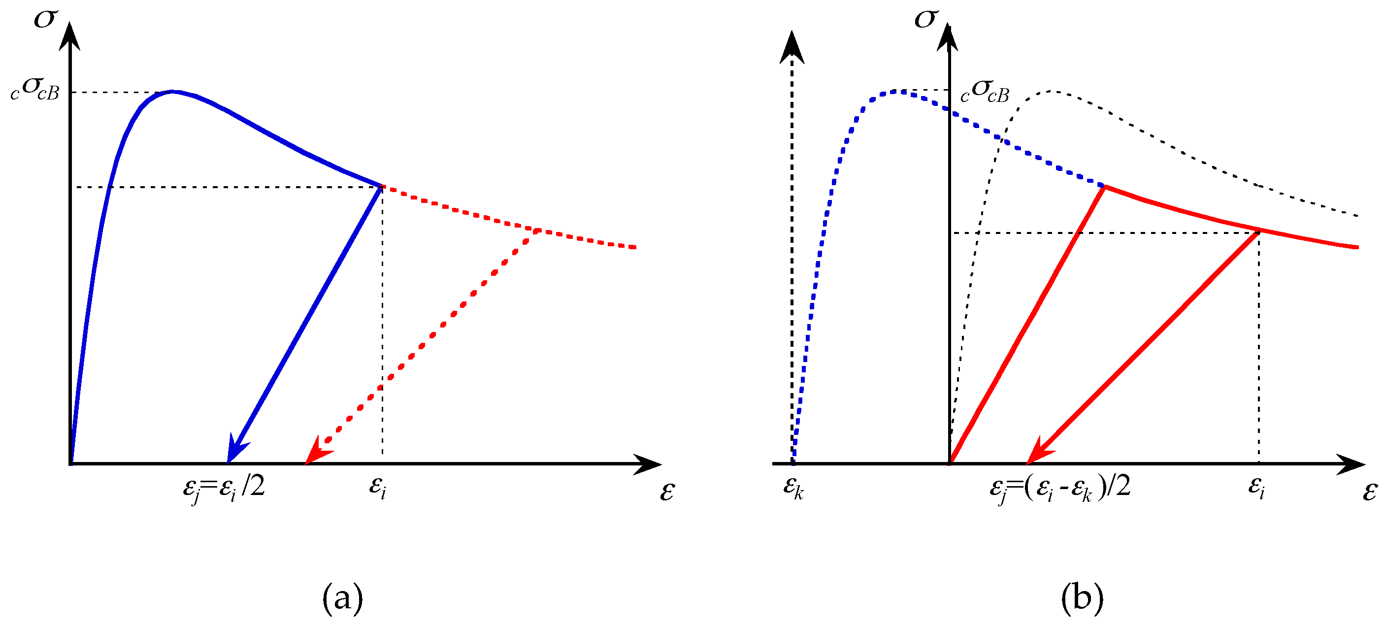
4.1. Numerical Analysis

A numerical analysis was conducted to explain the lower stiffness, higher load carrying capacity and overall behavior of the retrofitted columns. The bending moment versus the curvature relation was calculated using the so-called finite fiber method. The following assumptions were adopted: (1) the plane section remains planer after bending, (2) the tensile strength of concrete is ignored, (3) the shear deformation is ignored and (4) the rotation angle of the beam-column is concentrated within the plastic hinge region. The Sakino–Sun stress–strain relation was used for the concrete [8]. The bilinear model skeleton curve and Kato’s cyclic stress–strain curve were used for the steel and reinforcing bar [9]. The strain hardening coefficient was set at 0.005 for both the steel and reinforcing bars. The plastic hinge length was determined using Sakai’s model [10].
Generally, the lower stiffness observed in the second loading has been primarily attributed to the low rigidity of the epoxy resin and/or imperfection of the injection of the resin. However, even for specimens that experienced large deformation in the first loading, the maximum width of residual cracks was about 1 mm (see Figure 8). The summation of the residual crack widths in a range of 1.0 D (D = depth of column) from the column end was 2 mm at most. Considering the lower Young’s modulus and the much higher compressive strength of epoxy resin (see Figure 3), it could be said that the effect of the low rigidity of the epoxy resin on the retrofitted member’s lower stiffness was considerably limited.
In this paper, the deterioration of concrete rigidity caused by the first loading was taken into account for the second loading analysis. Figure 9 shows the stress–strain relation of concrete in the second loading. The last unloaded point in the first loading was taken as the origin for the hysteresis curve of concrete under the second loading. The hysteresis rule was also moved to the new origin. Furthermore, the stress during the second loading was assumed to be less than the skeleton curve of the first loading.
For a damaged and retrofitted specimen, the possibility exists that the yield stress of the yielded steel becomes higher than the initial one, because of strain aging and strain hardening. Herein, these effects were considered by assuming the yield stress as being 1.2 times the initial yield stress [11]. The yield stresses of the steel and reinforcing bar were thereby increased at the same rate.

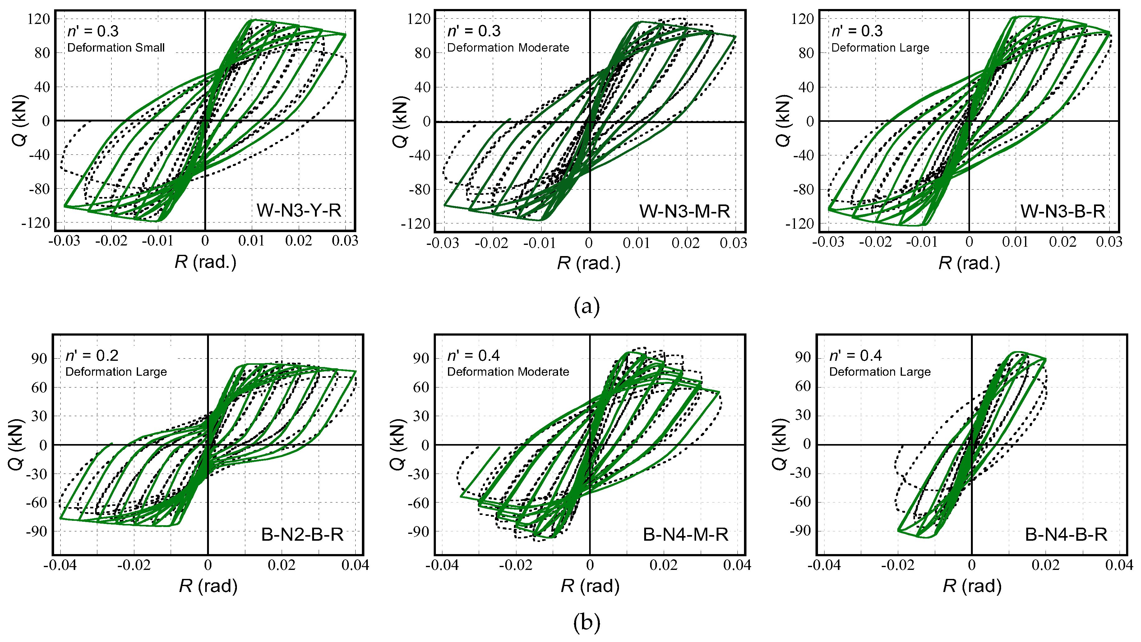
4.2. Comparison with the Experimentally Obtained Results

Figure 10 and Figure 11 present comparisons between the numerical and experimental behaviors. The dotted lines express the experimental results without considering the effects of strain aging and the hardening of the steels. Red and blue solid lines represent the numerical results. The numerical results predicted the stiffness reduction ratio and the experimental behaviors fairly well. However, in the case of the retrofitted beam-columns, the numerical results underestimated the experimental behavior, probably because of the effect of strain aging and/or the strain hardening of the steel. Figure 12 shows a comparison that incorporates an increment of 20% of the steel yield stress in order to consider the effects of strain aging and/or hardening, while Table 5 lists the calculated capacities along with comparisons with the measured results. From Figure 12 and Table 5, one can see that the numerical results can predict the measured ones much better in terms of the load-carrying capacities and post-peak behaviors compared with the numerical results, which do not consider the increase of yield stress, although the strength of the polymer cement mortar of the B Series is smaller than that of the original concrete.
Regardless of the connecting method of the batten plates, the numerical results considered above described the assumptions predicted the experimental behaviors well, which implies the validity of the numerical method presented in this paper for the evaluation of the structural performance of the retrofitted SRC columns. In the case of the bolt-connected specimens, the last loop behavior could not be predicted using the modified method, probably because the buckling of the main reinforcements was ignored in the analysis.

5. Conclusions

From the experimental and analytical results obtained for six open-web type SRC beam-columns described in this paper, the following conclusions can be drawn.
(1)
The initial stiffness of the retrofitted columns was lower than the initial ones. The lower stiffness might be attributed to the deterioration of the concrete rigidity, low rigidity of the resin and the polymer cement mortar, in addition to the imperfect injection of the resin.
(2)
The retrofitted SRC columns showed a higher load carrying capacity in case of weld-connected specimens, while the experienced displacement in each column differed. The higher load carrying capacity can be attributed to the effect of the strain aging and strain hardening of the steels. In the case of the bolt-connected specimen, the retrofitted columns showed approximately the same capacities as the initial columns. The effect of the buckling of the longitudinal reinforcing bars was observed in the column that experienced the larger displacement and higher axial load.
(3)
Analytical results predicted the stiffness reduction ratio and the experimental behaviors fairly well. However, for retrofitted beam-columns, the analytical results underestimate the experimental behavior.
(4)
Analytical results considering the increment of 20% of the yield stress of the steel due to strain aging and hardening predicted the experimental behaviors well, which implies the validity of the analytical method presented in this paper for the evaluation of the structural performance of retrofitted SRC columns.

Author Contributions

T.F. and Y.S. conceived and designed the paper, performed the experiments and wrote the paper. All authors have read and agreed to the published version of the manuscript.

Funding

This research was funded by the Ministry of Education, Culture, Sport, Science and Tecnology (MEXT), Grant-in-Aid for Young Scientists (B), grant number 20760375. This work was also supported by JSPS Grant no. R2904 in the Program for Fostering Globally Talented Researchers.

Acknowledgments

The authors would like to thank K. Nara, Y. Kamitani and T. Kume for technical assistance with the experiments.

Conflicts of Interest

The authors declare no conflict of interest. The funders had no role in the design of the study; in the collection, analyses, or interpretation of data; in the writing of the manuscript or in the decision to publish the results.

References

  1. Approach for Reduction of CO2 and Waste Emission through Life Cycle of Buildings. Available online: http://www.nilim.go.jp/lab/bcg/siryou/tnn/tnn0267pdf/ks0267011.pdf (accessed on 2 February 2020).
  2. American Concrete Institute. Concrete Repair Guide; ACI Committee 546: Farmington Hills, MI, USA, 1996. [Google Scholar]
  3. Japan Concrete Institute. Practical Guideline for Investigation, Repair and Strengthening of Cracked Concrete Structures 2009; Japan Concrete Institute: Tokyo, Japan, 1998. [Google Scholar]
  4. French, C.W.; Thorp, G.A.; Tsai, W.J. Epoxy Repair Techniques for Moderate Earthquake Damage. ACI Struct. J. 1990, 87, 416–424. [Google Scholar]
  5. Ekenel, M.; Myers, J.J. Durability performance of RC beams strengthened with epoxy injection and CFRP fabrics. Constr. Build. Mater. 2007, 21, 1182–1190. [Google Scholar] [CrossRef]
  6. Balsamo, A.; Colombo, A.; Manfredi, G.; Negro, P.; Prota, A. Seismic behavior of a full-scale RC frame repaired using CFRP laminates. Eng. Struct. 2005, 27, 769–780. [Google Scholar] [CrossRef]
  7. Editorial Committee for the Report on the Hanshin-Awaji Earthquake Disaster. Report on the Hanshin-Awaji Earthquake Disaster; Architectural Institute of Japan: Tokyo, Japan, 1998. [Google Scholar]
  8. Sakino, K.; Sun, Y. Stress–Strain Curve of Concrete Confined by Rectilinear Hoop. J. Struct. Constr. Eng. AIJ 1994, 461, 95–104. [Google Scholar] [CrossRef] [Green Version]
  9. Kato, B.; Akiyama, H.; Yamauchi, Y. Cyclic stress–strain relations for steel based on experimentally obtained results. In Proceedings of the Summaries of Technical Papers of Annual Meeting; AIJ: Tokyo, Japan, 1973; pp. 937–938. [Google Scholar]
  10. Sakai, J.; Matsui, C. Hysteresis Characteristic of Steel Reinforced Concrete Beam-Columns. J. Struct. Constr. Eng. AIJ 2000, 534, 183–190. [Google Scholar] [CrossRef] [Green Version]
  11. Fujinaga, T.; Sun, Y. Structural Performance of Damaged Open-web Type SRC Beam-columns after Retrofitting. In Proceedings of the 15th World Conference of Earthquake Engineering, Lisbon, Portugal, 24–28 September 2012. [Google Scholar]
Figure 1. Loading apparatus.
Sustainability 12 01381 g001
Figure 2. Reinforcement and steel details of the test specimen. (a) Weld-connected specimen (W Series); (b) Bolt-connected specimen (B Series).
Sustainability 12 01381 g002
Figure 3. Stress–strain relation of epoxy resin.
Sustainability 12 01381 g003
Figure 4. Procedure of retrofitting of the cross section. (a) Remove fragile parts; (b) Coat by primary resin; (c) Rebuild cross section with polymer cement mortar.
Sustainability 12 01381 g004
Figure 5. Procedure of injection of epoxy resin into the crack. (a) Remove surface dust; (b) Place tube attachments; (c) Caulk cracked parts; (d) Inject resin by inside pressure of tube; (e) Cure until resin hardens; (f) Finish the surface.
Sustainability 12 01381 g005
Figure 6. Relation between the horizontal load–drift ratio (W Series: weld-connected specimens). (a) First loading; (b) Second loading (after retrofitting).
Sustainability 12 01381 g006
Figure 7. Relation between the horizontal load–drift ratio (B Series: bolt-connected specimens). (a) First loading; (b) Second loading (after retrofitting).
Sustainability 12 01381 g007
Figure 8. Relation between the maximum width of the flexural crack and drift ratio. (a) Weld-connected specimen (W Series); (b) Bolt-connected specimen (B Series).
Sustainability 12 01381 g008
Figure 9. Assumed stress–strain relation of concrete. (a) First loading; (b) Second loading (after retrofitting).
Sustainability 12 01381 g009
Figure 10. Comparisons between the numerical and experimental results. (W Series: weld-connected specimens). (a) First loading; (b) Second loading (1.0 fy)
Sustainability 12 01381 g010
Figure 11. Comparisons between the numerical and experimental results (B Series: bolt-connected specimens). (a) First loading; (b) Second loading (1.0fy)
Sustainability 12 01381 g011
Figure 12. Comparison of analytically and experimentally obtained results (1.2fy). (a) W Series: weld-connected specimen; (b) B Series: bolt-connected specimen.
Sustainability 12 01381 g012
Table 1. Outlines of the test specimens.
SpecimensConnection of
Batten Plates
Axial Load Ratio
n = N/N0 1
Method of
Retrofitting
Young’s
Modulus
of Concrete
cE (GPa)
Compressive
Strength of Concrete
fc’ (MPa)
1st
loading
W-N3-YWeld-connected0.30-22.424.1
W-N3-M-21.023.6
W-N3-B-21.322.2
2nd
loading
W-N3-Y-R0.31Injection of epoxy21.223.4
W-N3-M-R20.023.1
W-N3-B-R0.29Section repair
Injection of epoxy
19.3
32.3 2
22.7
28.8 2
1st
loading
B-N2-BBolt-connected0.20-21.624.5
B-N4-M0.40-22.724.3
B-N4-B-23.824.1
2nd
loading
B-N2-B-R0.20Section repair
Injection of epoxy
23.8
10.2 2
26.3
20.1 2
B-N4-M-R0.4021.8
8.83 2
24.5
20.6 2
B-N4-B-R22.8
10.1 2
25.0
21.2 2
1N0 = cA fc’ + sA fy, 2 Polymer cement mortar
Table 2. Material properties of the steels used.
Young’s Modulus
sE (GPa)
Yield
Strength
fy (MPa)
Tensile
Strength
fu (MPa)
Yield
Ratio
Elongation
(%)
SteelFlange
/chord
W Series2053134360.71630.7
B Series2013544730.74831.5
Batten plate
(Web)
W Series2023404730.72035.5
B Series2123825200.73526.4
ReinforcementMain rebar
D13
W Series1933494970.70225.3
B Series1833554960.71523.6
Hoop
ϕ 6
W Series206678 17240.93711.2
B Series189391 15150.75825.7
1 0.2% offset yield strength.
Table 3. Material properties of the epoxy resin.
Young’s Modulus
rE (GPa)
Compressive
Strength
rfc (MPa)
Splitting Tensile
Strength
rft(MPa)
W Series3.0588.123.8
B Series3.2073.0-
Table 4. Primary experimental results.
SpecimensInitial Stiffness
(kN/mm)
Stiffness Reduction Ratio (%) 1Maximum Strength
(kN)
Deformation Ratio
at max. Strength (rad)
+-
1st
loading
W-N3-Y29.6-95.0-(0.0075)(−0.0075)
W-N3-M28.6-112.9-0.0143-0.0131
W-N3-B24.9-107.2-0.0128−0.0125
2nd
loading
W-N3-Y-R24.582.6115.41.080.0146−0.0135
W-N3-M-R22.879.7116.91.040.0189−0.0147
W-N3-B-R19.678.8109.81.030.0151−0.0201
1st
loading
B-N2-B32.9-86.9-(0.015)(−0.020)
B-N4-M37.2-104.8-0.014−0.013
B-N4-B34.4-105.9-0.015−0.012
2nd
loading
B-N2-B-R24.474.284.50.970.020−0.020
B-N4-M-R31.885.5100.90.960.014−0.014
B-N4-B-R24.671.490.20.850.013−0.013
1 the ratio of initial stiffness measured at second loading to that measured at the initial loading.
Table 5. Calculated results.
Stiffness Reduction RatioStrength Prediction Ratio (Exp./Ana.)
1.0fy1.2fy
Exp.Analysis
(Exp./Ana.)
max.0.005
rad
0.01
rad
0.02
rad
max.0.005
rad
0.01
rad
0.02
rad
W-N3-Y-R0.8140.909
(0.895)
1.0740.9101.0131.0720.9710.9100.9190.961
W-N3-M-R0.7970.814
(0.979)
1.1120.8630.9551.1391.0040.8630.8651.018
W-N3-B-R0.7870.905
(0.870)
0.9870.8210.8851.0240.8950.8210.8040.925
B-N2-B-R0.7420.765
(0.970)
1.1010.9830.9911.0510.9970.9830.9040.947
B-N4-M-R0.8550.669
(1.278)
1.1181.1011.0561.2551.0421.1010.9921.127
B-N4-B-R0.7140.617
(1.157)
1.0071.0730.9820.8930.9301.0730.9350.808

