Research on the Work Process of a Station for Preparing Forage


 , ,
, ,
Abstract
1. Introduction
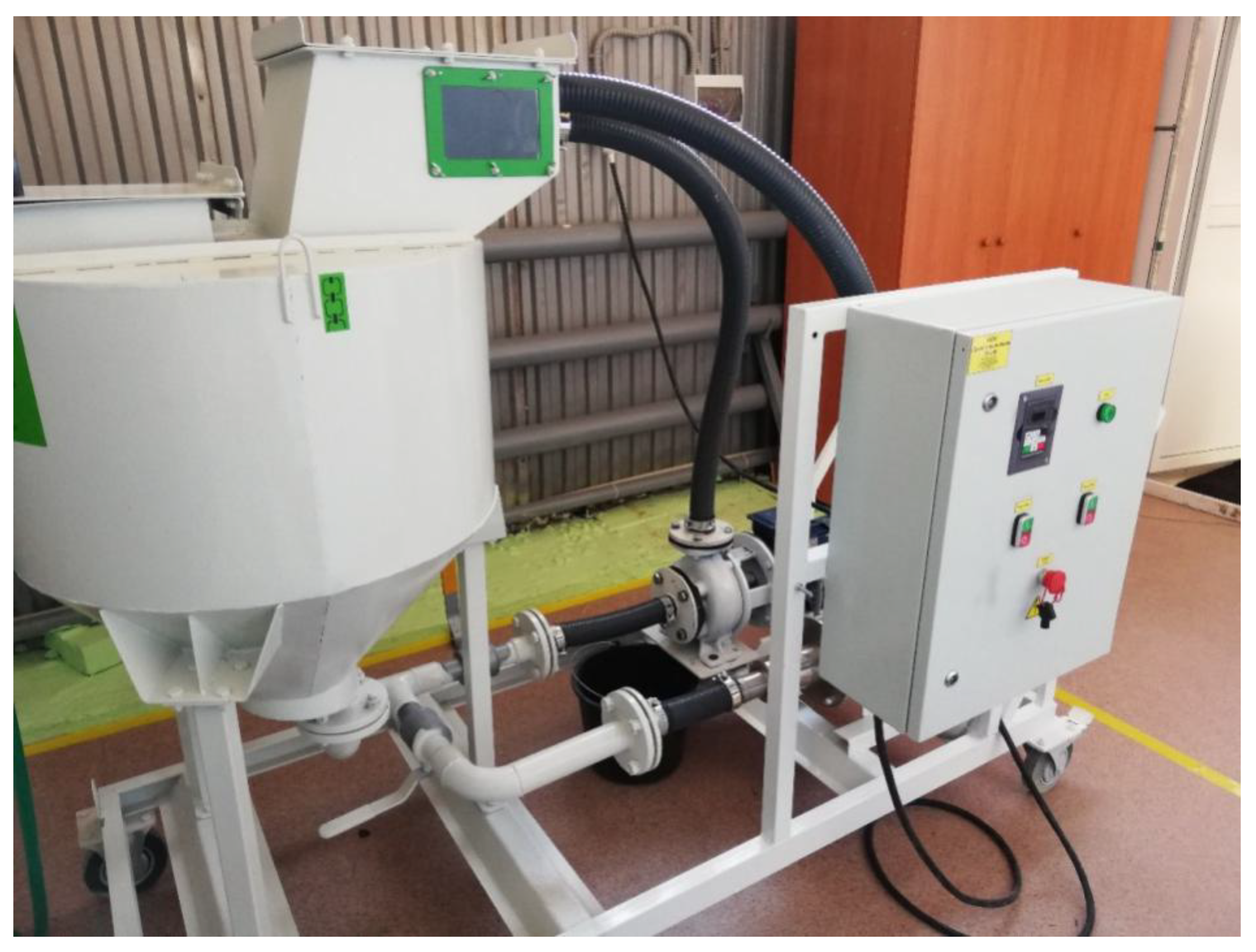
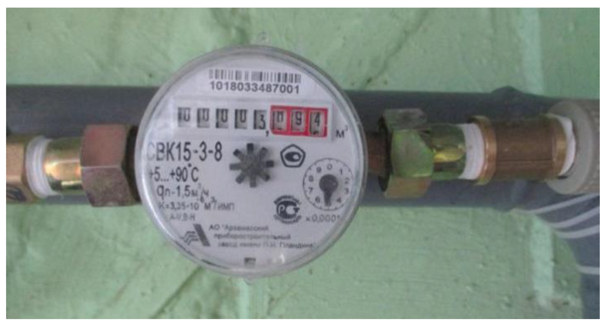
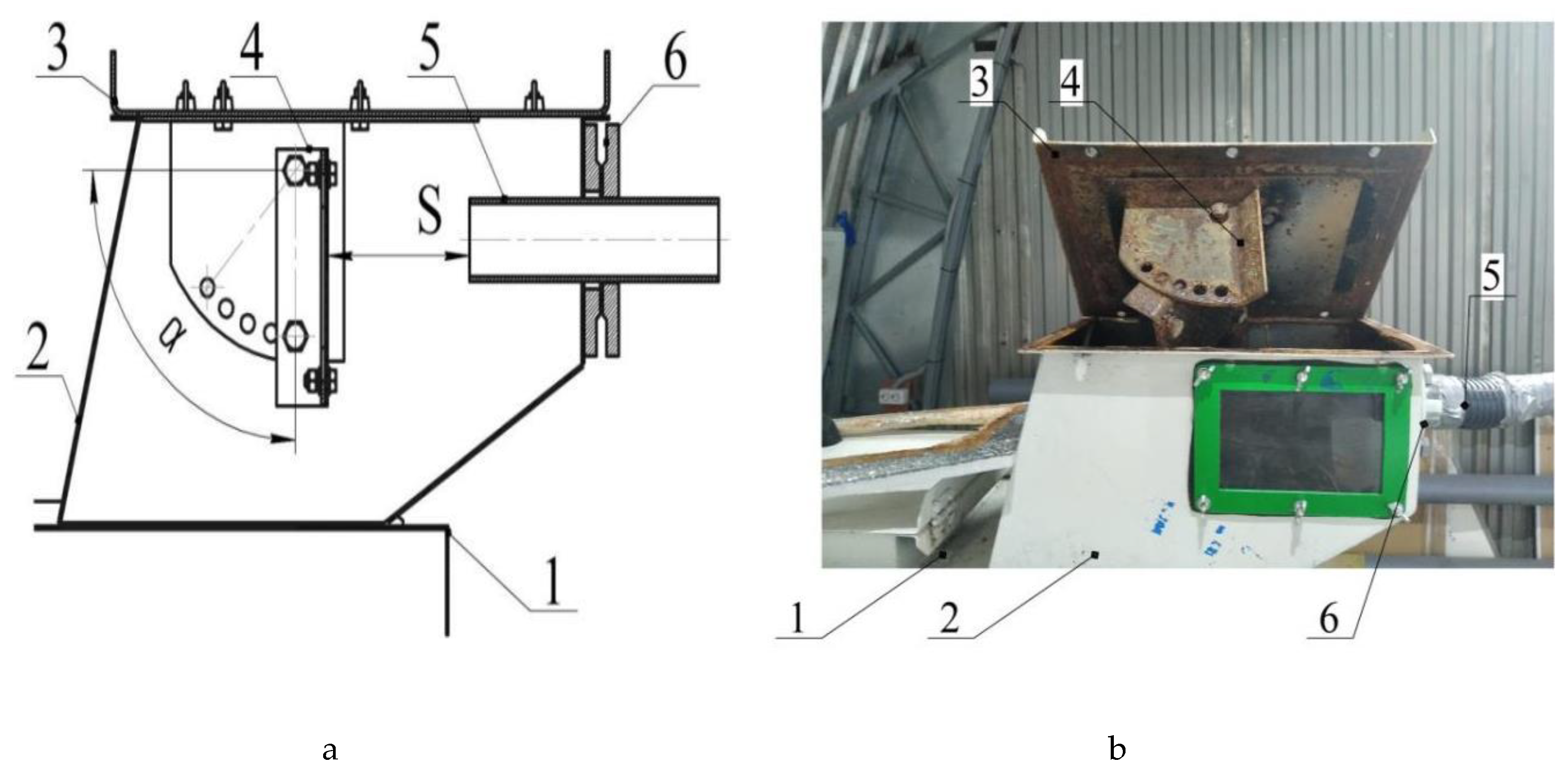
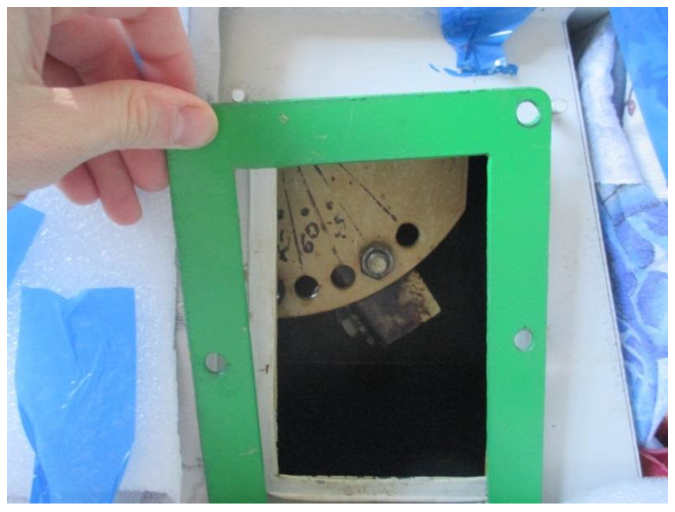
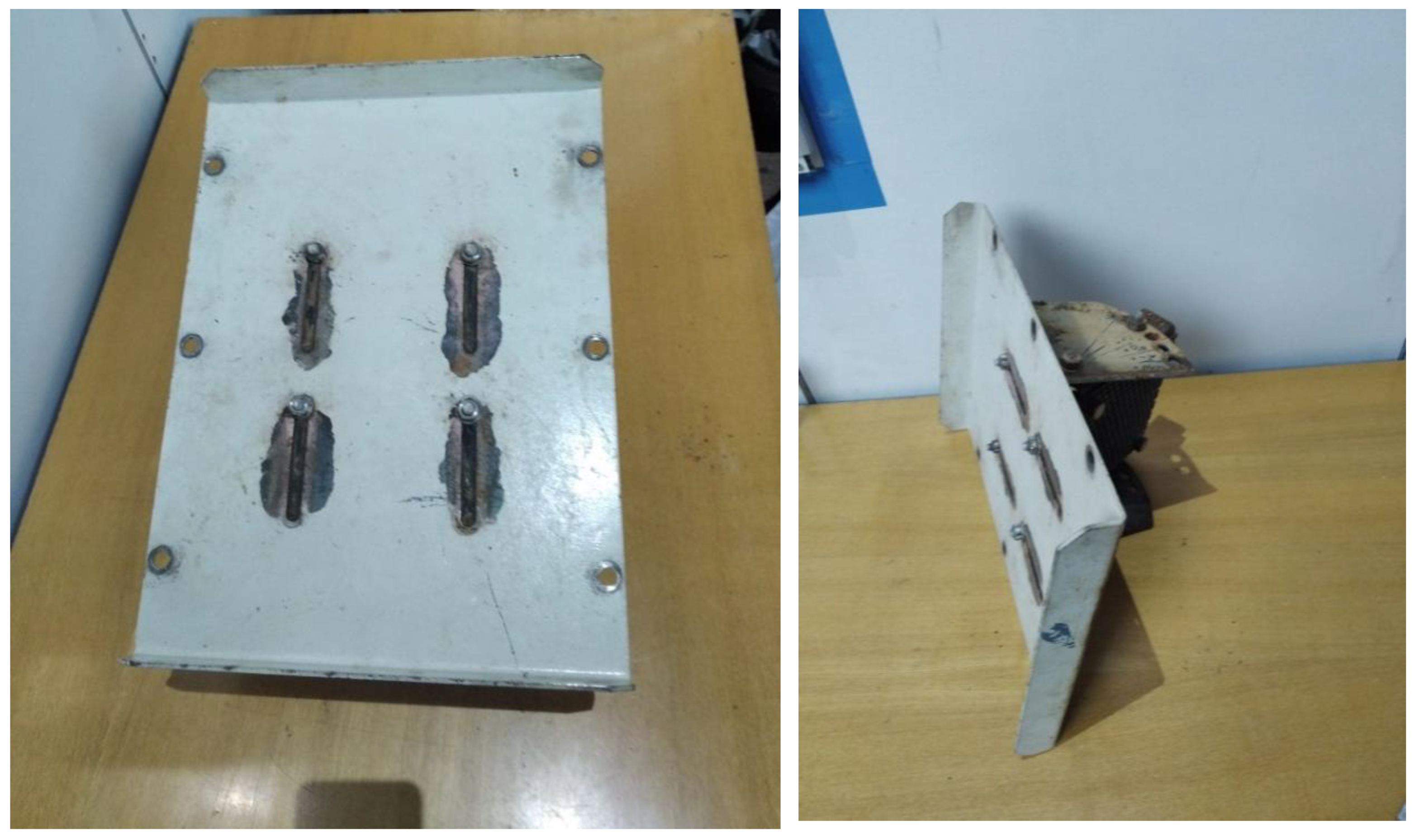
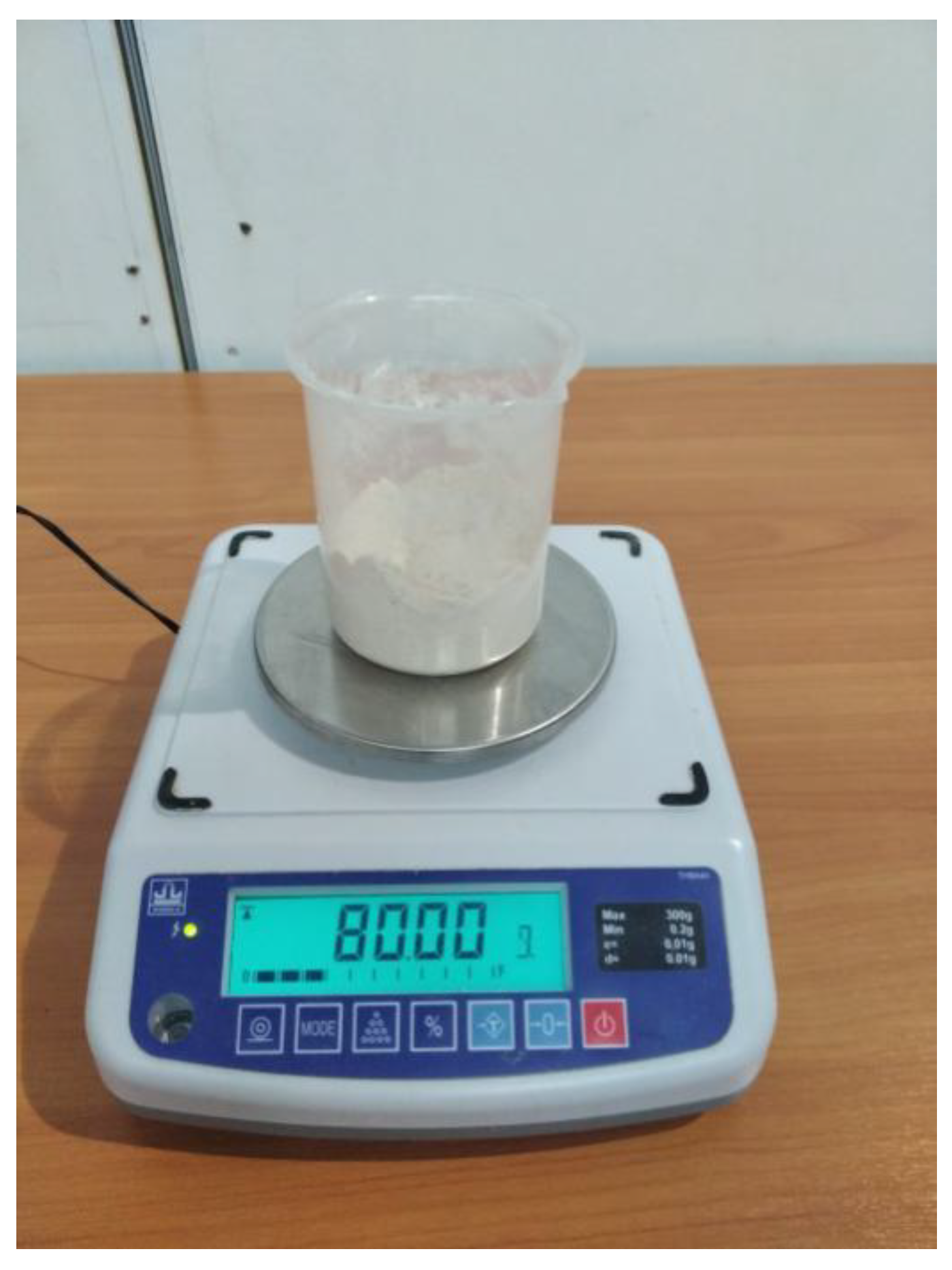
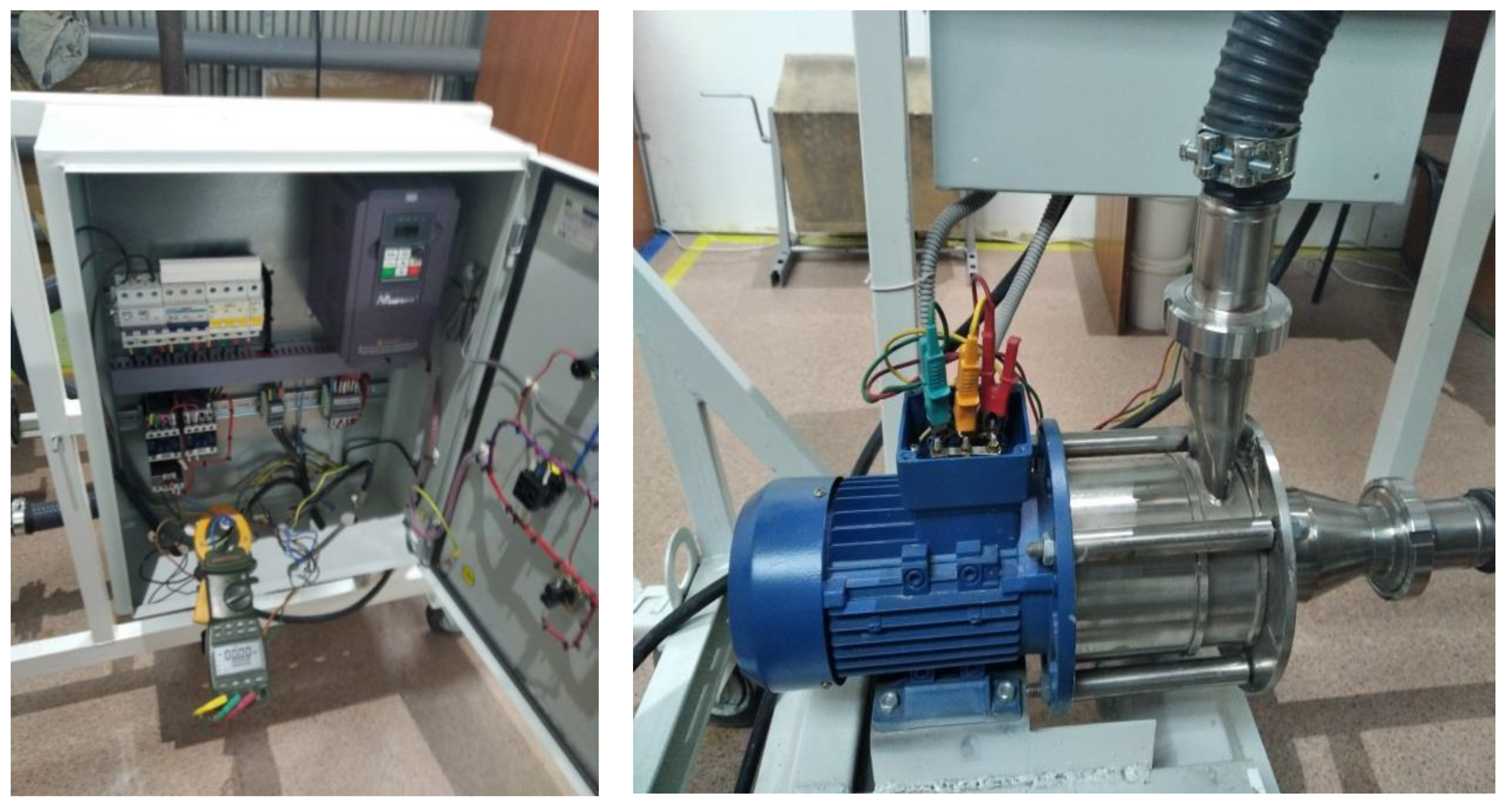
2. Materials and Methods
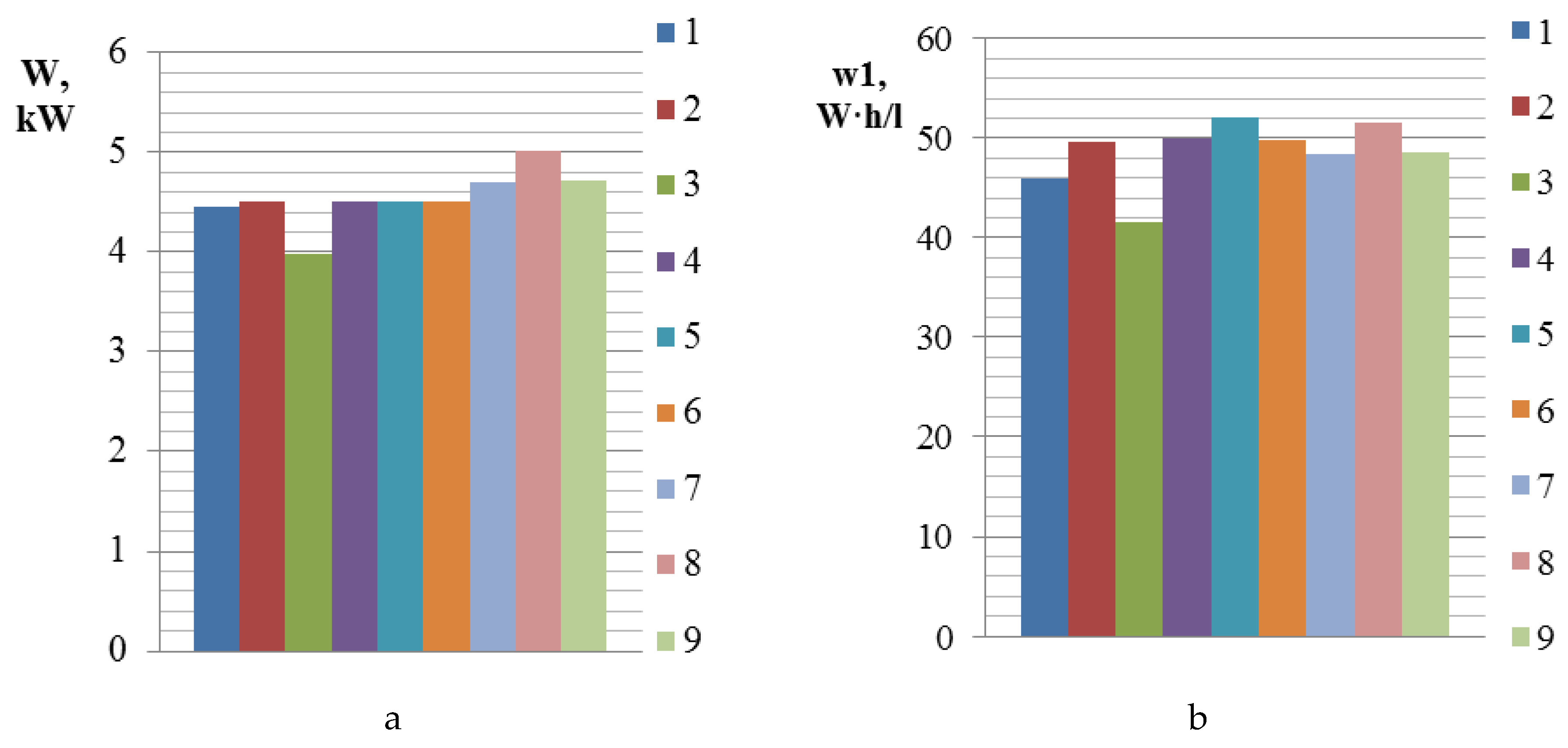
- is the average power consumption, kW;
- is the process time, s;
- is the volume of water and working mixture, l.
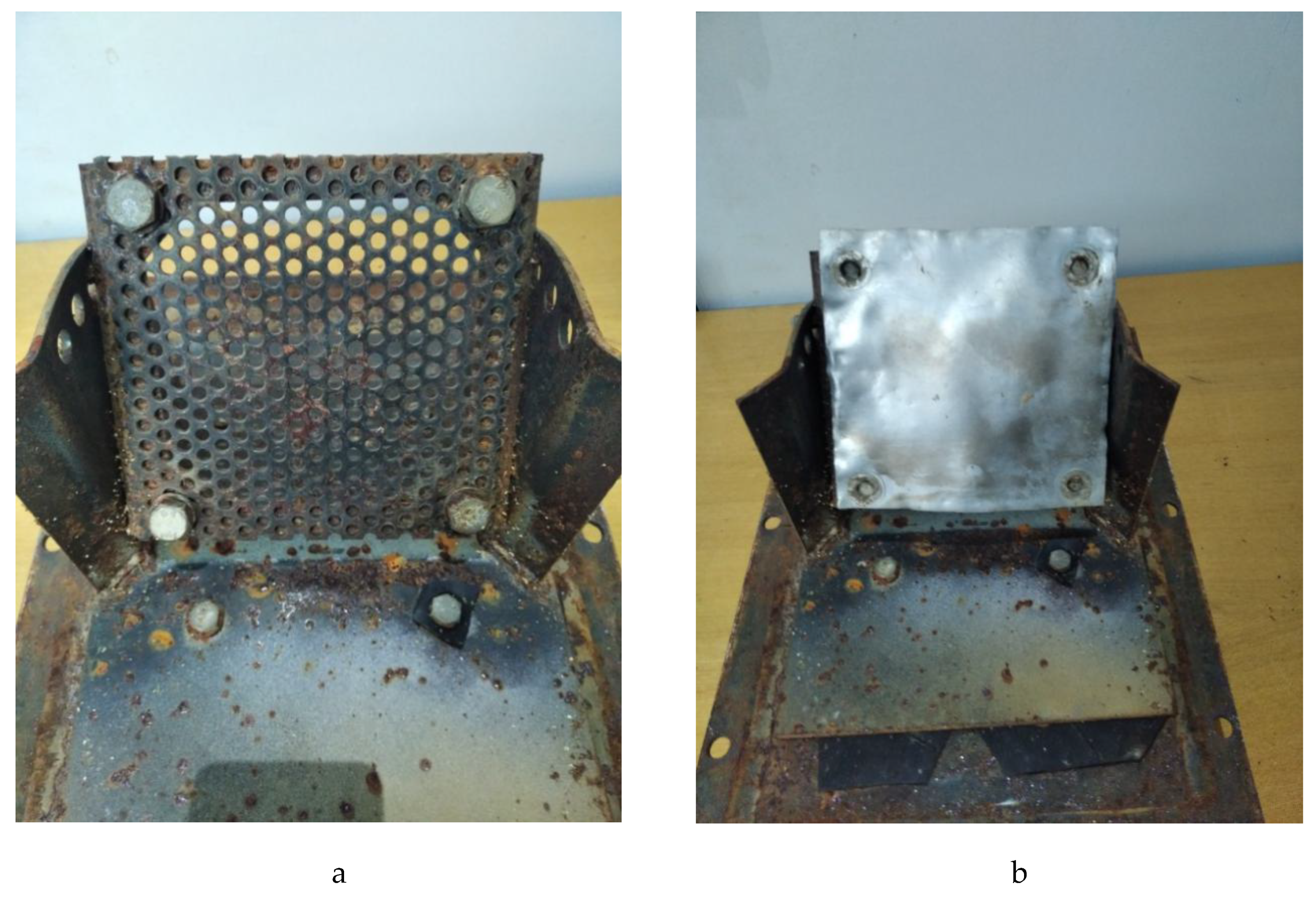
3. Results
4. Conclusions
Author Contributions
Funding
Acknowledgments
Conflicts of Interest
References
- Djuragic, O.; Levic, J.; Serdanovic, S.; Lević, L. Evaluation of homogeneity in feed by method of microtracers. Arch. Zootech. 2009, 12, 85–91. [Google Scholar]
- Flizikowski, J.; Tomporowski, A. Movement characteristics of multi-disc cereal crusher. Przemysł Chem. 2013, 92, 498–503. [Google Scholar]
- Flizikowski, J.; Sadkiewicz, J.; Tomporowski, A. Use characteristics of six-roll milling of grained raw materials for the chemical and food industry. Przemysł Chem. 2015, 94, 69–75. [Google Scholar]
- Tomporowski, B.; Flizikowski, J.; Kruszelnicka, W. A new concept for a cylindrical plate mill. Przemysł Chem. 2017, 96, 1750–1755. [Google Scholar]
- Svihus, B.; Kløvstad, K.H.; Perez, V.; Zimonja, O.; Sahlström, S.; Schüller, R.B.; Prestløkken, E. Physical and nutritional effects of pelleting of broiler chicken diets made from wheat ground to different coarsenesses by the use of roller mill and hammer mill. Anim. Feed Sci. Technol. 2004, 117, 281–293. [Google Scholar] [CrossRef]
- Sysuyev, V.A.; Aleshkin, A.V.; Savinykh, P.A. Feed-processing machines. In Theory, Development, Experiment; North-Eastern Zonal Agricultural Research & Development Institute: Kirov, Russia, 2008; Volume 1. [Google Scholar]
- Ali, E.; Morad, M.M.; Fouda, T.; Elmetwalli, A.; Derbala, A. Development of a local animal feed production line using programming control system. MISR J. Agric. Eng. 2016, 33, 181–194. [Google Scholar]
- Bulgakov, V.; Pascuzzi, S.; Ivanovs, S.; Kaletnik, G.; Yanovich, V. Angular oscillation model to predict the performance of a vibratory ball mill for the fine grinding. Biosyst. Eng. 2018, 171, 155–164. [Google Scholar] [CrossRef]
- Kusmierczak, S.; Majzner, T. Comprehensive approach to evaluation of degradation in chosen parts of energy equipment. Eng. Rural Dev. Proc. 2017, 12, 673–679. [Google Scholar]
- Bulgakov, V.; Holovach, I.; Bandura, V.; Ivanovs, S. A theoretical research of the grain milling technological process for roller mills with two degrees of freedom. INMATEH Agric. Eng. 2017, 52, 99–106. [Google Scholar]
- Savinykh, P.; Kazakov, V.; Czerniatiev, N.; Gerasimova, S.; Romanyuk, V.; Borek, K. Technology and equipment for obtaining starch syrup with ground and whole cereal grain. Agric. Eng. 2018, 22, 57–67. (In Russian) [Google Scholar]
- Vaculik, P.; Maloun, J.; Chladek, L.; Poikryl, M. Disintegration process in disc crushers. Res. Agric. Eng. 2013, 59, 98–104. [Google Scholar] [CrossRef]
- Yancey, N.; Wright, C.T.; Westover, T.L. Optimizing hammer mill performance through screen selection and hammer design. Biofuels 2013, 4, 85–94. [Google Scholar] [CrossRef]
- Ghorbani, Z.; Masoumi, A.; Hemmat, A. Specific energy consumption for reducing the size of alfalfa chops using a hammer mill. Biosyst. Eng. 2010, 105, 34–40. [Google Scholar] [CrossRef]
- Linke, B.S.; Dornfeld, D.A. Application of axiomatic design principles to identify more sustainable strategies for grinding. J. Manuf. Syst. 2012, 31, 412–419. [Google Scholar] [CrossRef][Green Version]
- Sysuev, V.; Savinyh, P.; Saitov, V.; Gałuszko, K.; Caban, J. Optimization of structural and technological parameters of a fermentor for feed heating. Agric. Eng. 2015, 12, 99. (In Russian) [Google Scholar]
- Motovilov, K.; Motovilov, O.; Aksyonov, V. Nanobiotechnology in the Production of Forage from Grain for Animal Husbandry: A Monograph; Publishing House of the Novosibirsk State Agrarian University: Novosibirsk, Russia, 2015. (In Russian) [Google Scholar]
- Donkova, N.; Donkov, S. Biotechnology for the production of sugars from grain raw materials. Bull. Krasn. State Agrar. Univ. 2014, 6, 211–213. (In Russian) [Google Scholar]
- Volkov, V. Efficiency of up-to-date equipment for the production of forage from grain. World Sci. Cult. Educ. 2013, 1, 351–354. (In Russian) [Google Scholar]
- Aksyonov, V. Up-dating the lines for obtaining feed forage from grain raw materials using cost-effectiveness analysis. Bull. Krasn. State Agrar. Univ. 2011, 12, 220–224. (In Russian) [Google Scholar]
- Novosibirsk Prototype Manufacturer of Non-Standard Equipment-Selmash LLC. Available online: http://noezno.ru/equipment/korm/kip-06/kip-06 (accessed on 12 April 2019).
- Agrotechnology. Available online: http://www.stav-agro.ru/index.php/katalog/urva-250.html (accessed on 15 May 2018).
- Agrobase. Available online: https://www.agrobase.ru (accessed on 12 April 2019).
- Short Feeding of Cattle. Available online: http://agrokorm.info/ru/kormoagregat-mriya-05/1/ (accessed on 12 April 2019).


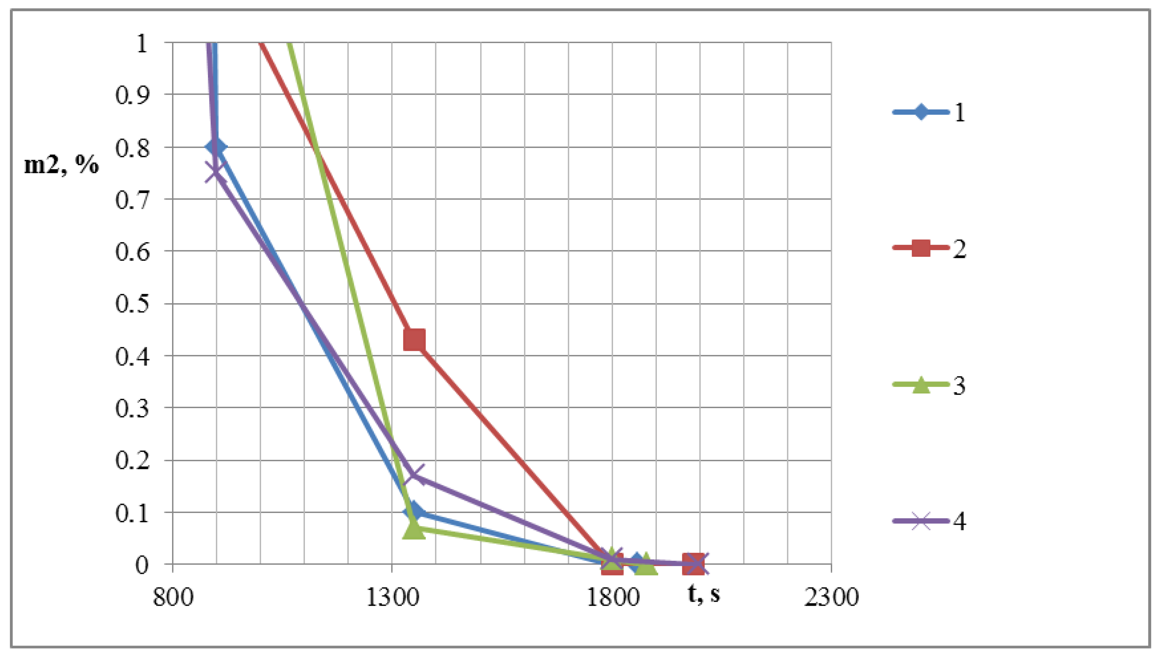
| Czas [s] | Number of whole grains in molasses when prepared using a grid-work (pcs.) | The residue on the sieve with a sieve size of 3 mm when prepared using a grid-work (%) | ||||
| M | SD | SKE | M | SD | SKE | |
| 1—distance from the grid-work to the nozzle is 140 mm, grid-work inclination angle is 30 degrees | ||||||
| 450 | 916 | 5.18 | −0.68 | 35.95 | 0.95 | 0.18 |
| 900 | 1 | 0.63 | 0 | 0.8 | 0.13 | 0 |
| 1350 | 0 | 0 | 0 | 0.1 | 0.05 | 0 |
| 1800 | 0 | 0 | 0 | 0 | 0 | 0 |
| 1857 | 0 | 0 | 0 | 0 | 0 | 0 |
| 2—distance from the grid-work to the nozzle is 140 mm, grid-work inclination angle is 45 degrees | ||||||
| 450 | 780 | 2.9 | 0.73 | 28.81 | 2.21 | −0.01 |
| 900 | 2 | 0.63 | 0 | 1.17 | 0.07 | −0.06 |
| 1350 | 0 | 0 | 0 | 0.43 | 0.1 | 0 |
| 1800 | 0 | 0 | 0 | 0 | 0 | 0 |
| 1984 | 0 | 0 | 0 | 0 | 0 | 0 |
| 3—distance from the grid-work to the nozzle is 205 mm, grid-work inclination angle is 30 degrees | ||||||
| 450 | 255 | 2.28 | −0.91 | 7.45 | 0.69 | −0.6 |
| 900 | 1 | 0.63 | 0 | 0.75 | 0.05 | −1.1 |
| 1350 | 0 | 0 | 0 | 0.17 | 0.01 | 0 |
| 1800 | 0 | 0 | 0 | 0.01 | 0 | 0 |
| 1998 | 0 | 0 | 0 | 0 | 0 | 0 |
| 4—distance from the plate to the nozzle is 205 mm, grid-work inclination angle is 45 degrees | ||||||
| 450 | 653 | 3.52 | −0.61 | 24.26 | 2.21 | 0.19 |
| 900 | 4 | 1.67 | −1.15 | 1.55 | 0.18 | −0.6 |
| 1350 | 0 | 0 | 0 | 0.07 | 0.01 | 0 |
| 1800 | 0 | 0 | 0 | 0.01 | 0 | 0 |
| 1878 | 0 | 0 | 0 | 0 | 0 | 0 |
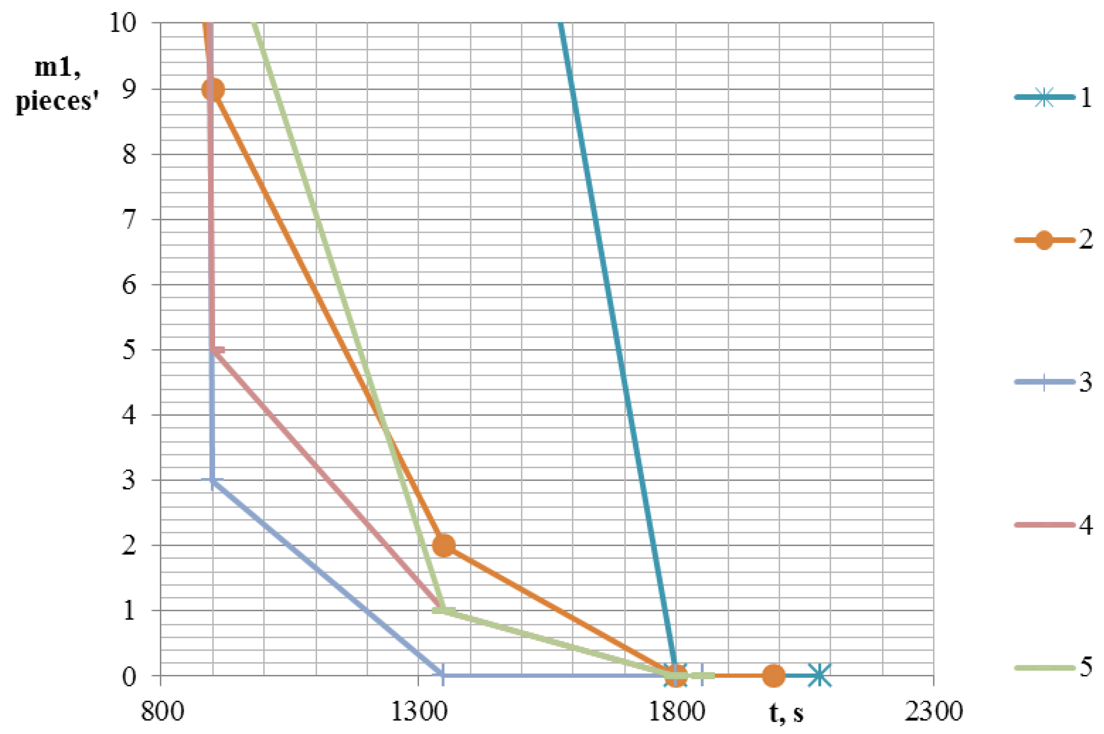
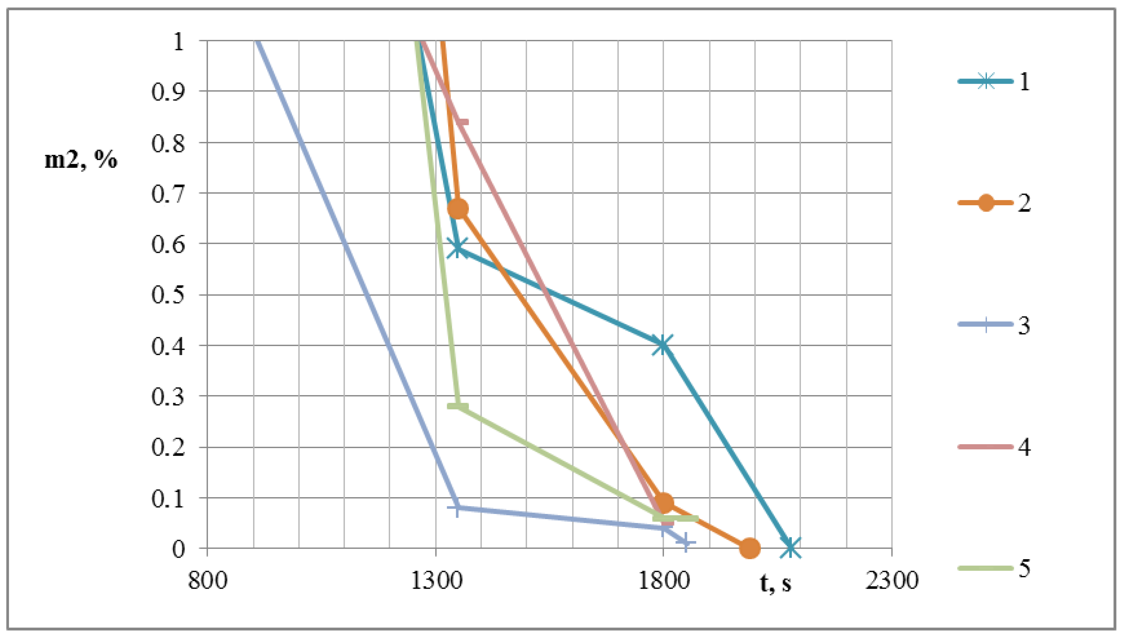
| Czas [s] | Number of whole grains in molasses when prepared using a plate [pcs.] | The residue on the sieve with a sieve size of 3 mm when prepared using a plate [%] | ||||
| M | S | SKE | M | S | SKE | |
| 1—distance from the plate to the nozzle is 140 mm, plate inclination angle is 30 degrees | ||||||
| 450 | 615 | 68.77 | 0.56 | 51.21 | 4.86 | −0.81 |
| 900 | 56 | 10.53 | 0.68 | 2.7 | 0.21 | 0.47 |
| 1350 | 20 | 3.16 | 0 | 0.59 | 0.04 | 0 |
| 1800 | 0 | 0 | 0 | 0.4 | 0.08 | 0 |
| 2080 | 0 | 0 | 0 | 0 | 0 | 0 |
| 2—distance from the plate to the nozzle is 140 mm, plate inclination angle is 45 degrees | ||||||
| 450 | 41 | 4 | 0.98 | 28.29 | 1.16 | −0.44 |
| 900 | 9 | 2.28 | 1.21 | 4.9 | 0.3 | −0.19 |
| 1350 | 2 | 0.63 | 0 | 0.67 | 0.06 | 0 |
| 1800 | 0 | 0 | 0 | 0.09 | 0.02 | 0 |
| 1989 | 0 | 0 | 0 | 0 | 0 | 0 |
| 3—distance from the plate to the nozzle is 140 mm, plate inclination angle is 90 degrees | ||||||
| 450 | 680 | 41.42 | −2.13 | 44.53 | 3.55 | −0.85 |
| 900 | 3 | 1.1 | 1.36 | 1.02 | 0.13 | −0.1 |
| 1350 | 0 | 0 | 0 | 0.08 | 0.02 | 0 |
| 1800 | 0 | 0 | 0 | 0.04 | 0 | 0 |
| 1851 | 0 | 0 | 0 | 0.01 | 0 | 0 |
| 4—distance from the plate to the nozzle is 205 mm, plate inclination angle is 90 degrees | ||||||
| 450 | 400 | 4.69 | −0.26 | 400 | 15.61 | 0.72 |
| 900 | 5 | 2.76 | −0.09 | 5 | 1.67 | −0.38 |
| 1350 | 1 | 5.18 | 0 | 1 | 0.46 | 0 |
| 1800 | 0 | 2.83 | 0 | 0 | 0 | 0 |
| 1852 | 0 | 6.42 | 0 | 0 | 0 | 0 |
| 5—distance from the plate to the nozzle is 305 mm, plate inclination angle is 90 degrees | ||||||
| 450 | 400 | 1.41 | 2 | 400 | 17.52 | 1.93 |
| 900 | 12 | 4.05 | 3 | 12 | 2.53 | 2.1 |
| 1350 | 1 | 4.69 | 4 | 1 | 0.38 | −0.25 |
| 1800 | 0 | 3.85 | 5 | 0 | 0 | 0 |
| 1852 | 0 | 7.21 | 6 | 0 | 0 | 0 |
© 2020 by the authors. Licensee MDPI, Basel, Switzerland. This article is an open access article distributed under the terms and conditions of the Creative Commons Attribution (CC BY) license (http://creativecommons.org/licenses/by/4.0/).
Share and Cite
Marczuk, A.; Misztal, W.; Bulatov, S.; Nechayev, V.; Savinykh, P. Research on the Work Process of a Station for Preparing Forage. Sustainability 2020, 12, 1050. https://doi.org/10.3390/su12031050
Marczuk A, Misztal W, Bulatov S, Nechayev V, Savinykh P. Research on the Work Process of a Station for Preparing Forage. Sustainability. 2020; 12(3):1050. https://doi.org/10.3390/su12031050
Chicago/Turabian StyleMarczuk, Andrzej, Wojciech Misztal, Sergey Bulatov, Vladimir Nechayev, and Petr Savinykh. 2020. "Research on the Work Process of a Station for Preparing Forage" Sustainability 12, no. 3: 1050. https://doi.org/10.3390/su12031050
APA StyleMarczuk, A., Misztal, W., Bulatov, S., Nechayev, V., & Savinykh, P. (2020). Research on the Work Process of a Station for Preparing Forage. Sustainability, 12(3), 1050. https://doi.org/10.3390/su12031050