Article

Joint Analysis of Cost and Energy Savings for Preliminary Design Alternative Assessment

Department of Civil and Environmental Engineering, Politecnico di Milano, 20133 Milan, Italy
*
Author to whom correspondence should be addressed.
Sustainability 2020, 12(18), 7507; https://doi.org/10.3390/su12187507
Submission received: 18 August 2020 / Revised: 3 September 2020 / Accepted: 6 September 2020 / Published: 11 September 2020
(This article belongs to the Section Sustainable Engineering and Science)

Abstract

:
The building sector plays a central role in addressing the problem of global energy consumption. Therefore, effective design measures need to be taken to ensure efficient usage and management of new structures. The challenging task for designers is to reduce energy demands while maintaining a high-quality indoor environment and low costs of construction and operations. This study proposes a methodological framework that enables decision-makers to resolve conflicts between energy demand and life cycle costs. A case study is analyzed to validate the proposed method, adopting different solutions for walls, roofs, floors, windows, window-to-wall ratios and geographical locations. Models are created on the basis of all the possible combinations between these elements, enriched by their thermal properties and construction/management costs. After the alternative models are defined, energy analyses are carried out for an estimation of consumption. By calculating the total cost of each model as the sum of construction, energy and maintenance costs, a joint analysis is carried out for variable life cycles. The obtained results from the proposed method confirm the importance of a preliminary assessment from both energy and cost points of view, and demonstrate the impact of considering different building life cycles on the choice of design alternatives.

1. Introduction

The construction industry is commonly known as “the industry of the 40%”, due to the fact that buildings produce nearly 40% of overall CO2 emissions, generate 40% of overall waste and consume 40% of overall natural resources over their life-spans [1]. In 2016, it was estimated that in EU countries, the amount of total household waste generated was more than 200 million tons/year, of which 18% was recyclable [2]. Moreover, the building sector accounts for half of global electricity demands and 30% of CO2 emissions. The overall use of electricity in buildings has grown by an average of 2.5% per year since 2010, when CO2 emissions from buildings started to increase at a rate of approximately 1% per year. However, two-thirds of all countries still do not have mandatory energy codes for this sector [3]. It is interesting to note that in the construction sector, the most energy is consumed during the operating phases of buildings, that is, for heating, cooling, lighting and providing hot water [1].
Indeed, continuous rapid socio-economic growth requires that the building sector provide continuous improvement to people’s living conditions, which means good living environments and high-demand building configurations. This leads to a growing demand worldwide for improved comfort, especially in developing countries. Thus, to provide indoor air comfort to occupants, it is generally necessary to implement mechanical means of heating and cooling. Hence, the building sector in urban areas is becoming increasingly energy consumptive. It has been estimated that even if all the energy efficiency policies are implemented with great success, global primary energy demand is still expected to increase by 35% by 2040 [4]. This scenario is generating growing concern regarding the impact that the building sector may have on the environment and what can be done to improve sustainability in this industry.
There is a need to find new passive strategies for providing occupants with indoor air comfort to reduce dependency on mechanical heating/cooling and reduce the negative impact of the building industry on the environment. As a result, the modeling of energy performance is a critical issue for the management of energy efficiency in buildings [1]. Several tools and methods have been assessed to support the implementation of sustainable strategies in the built environment.
As previously mentioned, most energy consumption occurs during the operating phase of a facility. At this point, interventions aiming at increasing the sustainability of the asset can be difficult to implement and are particularly expensive. For this reason, prompt and informed decisions regarding the best design alternatives should be made before the construction phase. This should be completed taking into account not only environmental, but also economical sustainability. The best compromise of balancing costs and energy savings should be chosen in order to make effective solutions more affordable.
Due to its characteristics, building information modelling (BIM) technology is the best approach to address this problem [5]. Through a BIM-based model, it is possible to define the thermal characteristics of each element of the building; this makes it possible to perform energy analyses in advance, allowing for a more informed decision-making process. Focusing on the design stage, at the same time that the virtual counterpart of the building is analyzed from an energy consumption point of view, costs and many other related factors can be analyzed as well, providing the possibility of exploring several options and identifying the best one [6,7,8]. In the literature, many publications have examined the important role of BIM, and there are examples of it being used to optimize different aspects of a project. For instance, Raut et al. [9] analyzed the effectiveness of various roof systems with different insulations layers in a hot climatic condition in India. They analyzed both annual energy use and related costs to understand occupants’ indoor comfort level, as well as the environmental and long-term economic benefits of insulation for a building envelope. This research allows one to gain an understanding of how to use the BIM approach to link costs to energy consumption. Costs were also considered by Jalilzadehazhari et al. [10]. The authors used the incorporation of BIM, experimental design and an analytical hierarchy process to obtain an analysis of the performance of 375 construction solutions, considering different solutions based on a trade-off among visual comfort, thermal comfort, energy demand and life cycle costs. As optimization variables, three types of windows and five types of ground floors, roofs and external wall constructions with different thermal transmittance values were considered. The results were used to obtain two different main scenarios. The former concentrated on the importance of visual and thermal comfort, while the latter focused on a further decrease in life cycle costs. Sandberg et al. [11] conducted similar research, focusing their attention on the problem of designing a BIM-based process using neutral file formats to achieve multidisciplinary optimization of life cycle energy and costs. The authors proposed a framework consisting of a centralized master model, from which different discipline-specific domain models were generated and evaluated, and an optimization algorithm to control the loop. The main goal was to enhance the building’s sustainability performance by optimizing the trade-off between the building’s life cycle energy and life cycle cost, considering different alternatives for the material. Singh and Sadhu [12] considered not only different materials for roofs and walls, but also variable window-to-wall ratios (WWR), different orientations in space and combinations of building networks.
The selection of different software packages is fundamental to obtaining good interoperability between project participants. Spiridigliozzi et al. [13] conducted research in which they modelled a single dwelling of two-floor sites with Autodesk Revit®; they then imported it into the IDA Indoor Climate and Energy (IDA-ICE) simulation tool to determine the energy demand variations from one month to the next. The aim of the authors was to demonstrate how crucial good interoperability is when designers decide to perform energy analyses through BIM and building energy modeling (BEM). A similar approach was used by Tallberg and Bohne [14], who reported a BIM-based iterative energy performance simulation performed with IDA-ICE, aiming at establishing a procedure for techno-economic optimization. The authors evaluated the energy performance of a traditional apartment building designed with the Norwegian TEK-17 standards and compared the results with the recommended thermal properties given by the nZEB (nearly Zero Emission Buildings) standards. In this paper, two possible standardizations that may be helpful for designers making decisions about a building’s elements were proposed.
In this field, Leadership in Energy and Environmental Design (LEED) is one of the most widely used green building rating systems to quantify the level of sustainability. This was used by Akcay and Arditi [15], who described a useful method for obtaining the desired number of points in the “Optimize Energy Performance” credit of the “Energy and Atmosphere” category of LEED certification at minimum cost. They modelled different scenarios and identified the LEED points and costs of each of them. The connection between life cycle assessment (LCA), building green certificate production and BIM was also investigated by Veselka et al. [16]. In particular, the latter authors investigated four different certification systems, assessed the BIM-based workflow usage as input for LCA and provided suggestions for developing building models which were LCA compliant for a smooth and almost automatic certificate production. In the same field, Palumbo et al. [17] presented a method for achieving accurate LCA results by integrating Environmental Product Declarations (EPDs) into BIM models at different levels of development (LOD).
The problems of negative environmental impact, obviously, is not only related to new constructions; for this reason, several studies have focused on analyzing existing buildings. Montiel-Santiago et al. [18] presented the case of a building for sanitary use. They constructed an energy model for it and identified possible alternatives to improve energy efficiency and lightning, as well as analyzed the possibilities of incorporating other, more efficient forms of renewable energy, such the use of daylight. Ijasahmed et al. [19] modelled an existing single storey building and performed energy analyses comparing the performance of the real structure with the modelled one incorporating passive features (roof and wall insulation, double glazing for windows and a high-efficiency air conditioning system) and renewable energy systems. Maciel and Carvalho [20] focused on residential buildings in Brazil. The research investigated the energy benefits of opaque ventilated façades compared to cladding façades in multifloor residential buildings located in nine climate zones in Brazil. The authors considered the cost of implementing such a system in different locations to determine the cost benefit against the yearly energy benefits. They observed the greatest energy and cost benefits in the warmer regions. Mirrahimi et al. [21] considered the Malaysian tropical climate. The authors studied the passive design method to reduce the environmental impact of a building, which is one of the most promising strategies for hot-humid tropical regions. They made a selection of fundamental elements (shape, width, length, height, external walls, roof, glazing area and external shading devices) to determine the best natural ventilation and occupant thermal comfort. On the basis of their and other studies, they provided recommendations to help designers choose various elements. Sadeghifam et al. [4] conducted a similar research. They considered different types of floor, walls, windows and ceilings, and through the Taguchi statistical method, they determined the level of importance of the building components in term of energy insulation, also considering the effects of noise factors such as temperature, humidity and air flow.
Examples of studies focusing on the optimization of environmental sustainability and economic burden can be found in the works of Zachariadis et al. [22] and Astiaso Garcia et al. [23]. The former authors proposed an approach to assess the economically viable energy efficiency potential of the building sector of Cyprus, with a combination of detailed engineering modelling, cost-effectiveness calculations and real-world considerations of budgetary, technical, behavioral and market constraints. They came up with a proposal for prioritizing specific energy investments without ignoring other measures that may be economically less favorable but realistically implemented in a limited number of buildings. In the latter, they provided preliminary information about the economic costs and energy benefits of some considered interventions in existing public buildings. By assessing the building global energy performance indexes before and after each intervention and estimating their costs by averaging the amount demanded by different companies for the same intervention, they compared the relationship between energy consumption reduction and costs.
Starting from what other authors have done in the reported literature, the aim of this work is to exploit the potential of BIM technology to improve the decision-making process regarding the overall sustainability of a building which is yet to be constructed. Taking this into account, this work proposes a methodological framework to improve energy efficiency, focusing on elements with precise commercial characteristics and costs. This framework has been tested and verified to be robust and replicable for other, different situations.

2. Methodology

The workflow of the proposed methodology is graphically presented in Figure 1.
As shown, the first step consists of the geometric modelling of the building under analysis. This means defining, for each building component (walls, roofs, floors and so on), the dimensions, position and shape, in order to determine the areas and volumes of the spaces of the structure. Since the purpose of this work is to compare different design alternatives, the key point is defining which construction component typologies to consider, in relation to their impact in terms of the cost and energy consumption of the whole building. In this study, four building components are selected to be differently combined so as to have several alternatives, i.e., the walls, roofs, floors and windows. Additionally, the WWR is investigated. WWR represents the ratio between the total window glass surface and the total external wall surface. For these elements, a definition of their composition is necessary to precisely characterize cost and thermal properties.
Walls, roofs and floors need to be characterized in terms of thickness and stratigraphy. For each of them, different typologies can be defined depending, for instance, on the materials used for insulation, finishing and structural cores. Windows can be characterized by the material used for the frame and the type of glass.
Depending on how many typologies of building components and variables are evaluated, a different total number of design alternatives is obtained. Considering two typologies for each of the four selected building components and three different WWRs, 48 design alternatives were obtained. For each of them, the model yields information related to costs and thermal properties, making it possible to perform energy analyses, calculate quantities and make costs estimates.
Regarding the energy analysis, the main parameters that must be specified for each building component are:
  • thermal conductivity λ (expressed in W/m∙K), which describes the capacity of a material to conduct heat when there is a difference of temperature. It depends on the nature of the material, but not on its shape;
  • thermal transmittance U (expressed as W/m2∙K), which describes the tendency of an element to disperse heat in the presence of a temperature difference.
These two parameters define the passive thermal behavior of the components constituting the building. Active systems like HVAC (Heating, Ventilation and Air Conditioning) systems should be properly defined as well. In fact, different solutions lead to different expected energy consumption. Other factors that affect the energy demands of a building are, for instance, the typology of the activities expected to be carried out, the geometry and orientation of the envelope or the presence of nearby buildings. For the sake of simplicity, in this study, the design alternatives to be compared will differ according to the thermal transmittance of the building components, while all the other factors will not be considered, i.e., they will be left the same for each model.
In this study, the evaluation of the energy consumptions is expressed in terms of EUI (Energy Use Intensity). This choice was made due to the fact that EUI is gaining popularity among governmental organizations, nongovernment organizations and building industry groups [1], including American Society of Heating, Refrigerating and Air-Conditioning Engineers (ASHRAE) [24]. This index represents the total energy consumed by a building in one year per unit area, and is usually expressed in MJ/m2/year or kWh/m2/year [25] (1 kWh = 3.6 MJ). In Figure 2, a schematic representation of the meaning of EUI and the parameters that can affect it is reported. Computing this value for each design alternative makes it possible to perform detailed comparisons.
More efficient building components, as one might expect, improve energy savings, but their impact on the manufacturing, installation and maintenance costs must also be taken into account. For this reason, assessments of design alternatives must implement all these aspects in some way. The total cost of building Ctot can be assumed to be:
Ctot = Cc + Cm + Cu
where Cc represents the cost of construction just before the hand-over, and comprises costs of manufacturing and installation; Cm stands for expected maintenance costs during the operation phase of the building and could be different in terms of both entity and periodicity, depending on the quality and technology of the building components; Cu represents the cost of the consumed energy during the expected life cycle of the building. Assuming a time constant, the average cost of the energy and the maintenance operations (properly executed, i.e., assuring no loss of efficiency of the building) can be expressed as:
Cu = Ny·Cy
where Cy is the annual energy cost and Ny the expected life cycle of the building, expressed in years. Regarding how Ctot is expressed, it is possible to make comparisons considering different expected life cycles of the structure. While Cc is associated with the construction phase, Cm and Cu vary from year to year, the former periodically and the latter at a constant rate; the longer the considered life cycle, the greater the impact of Cm and Cu on Ctot.
On the basis of the computed EUI and Ctot of each design alternative, it would be easy to find the best solution (smaller EUI) or the cheapest one (smaller Ctot); in such a scenario, it would be expected that the result would comprise two opposing design alternatives (e.g., more efficient but more expensive, or less efficient and cheaper). Hence, it is more interesting finding the optimum, taking into account both criteria. In particular, it is important to determine building components which would be worth investing in. To this end, the assessment can be made on the basis of the ratio between the difference of the total costs associated with creating a more efficient building component and the improvement in terms of the correspondent energy saving, which may be expressed as:
IR = ∆Ctot/∆EUI
where IR is the “Investment Ratio”. Assuming two types of building components, i.e., 1 and 2, where the latter is more efficient than the first, ∆Ctot and ∆EUI are:
∆Ctot = Ctot (2) − Ctot (1)
∆EUI = EUI (1) − EUI (2)
For a good result, the IR must be as low as possible. In fact, it can be lowered increasing ΔEUI (corresponding to an improvement in overall energy efficiency) or decreasing ∆Ctot (small cost difference between two types of the same building component). Basically, it expresses the cost of a unitary improvement of energy saving. Note that in cases whereby a more effective component is also cheaper, the IR is negative. Considering the values of Ctot and EUI computed for each design alternative, Ctot (i) and EUI (i) (being i of types 1 and 2) are the average of the values obtained by all the models using components of type 1 or 2. This is done for different expected life cycles in order to determine the variability of Ctot over time.

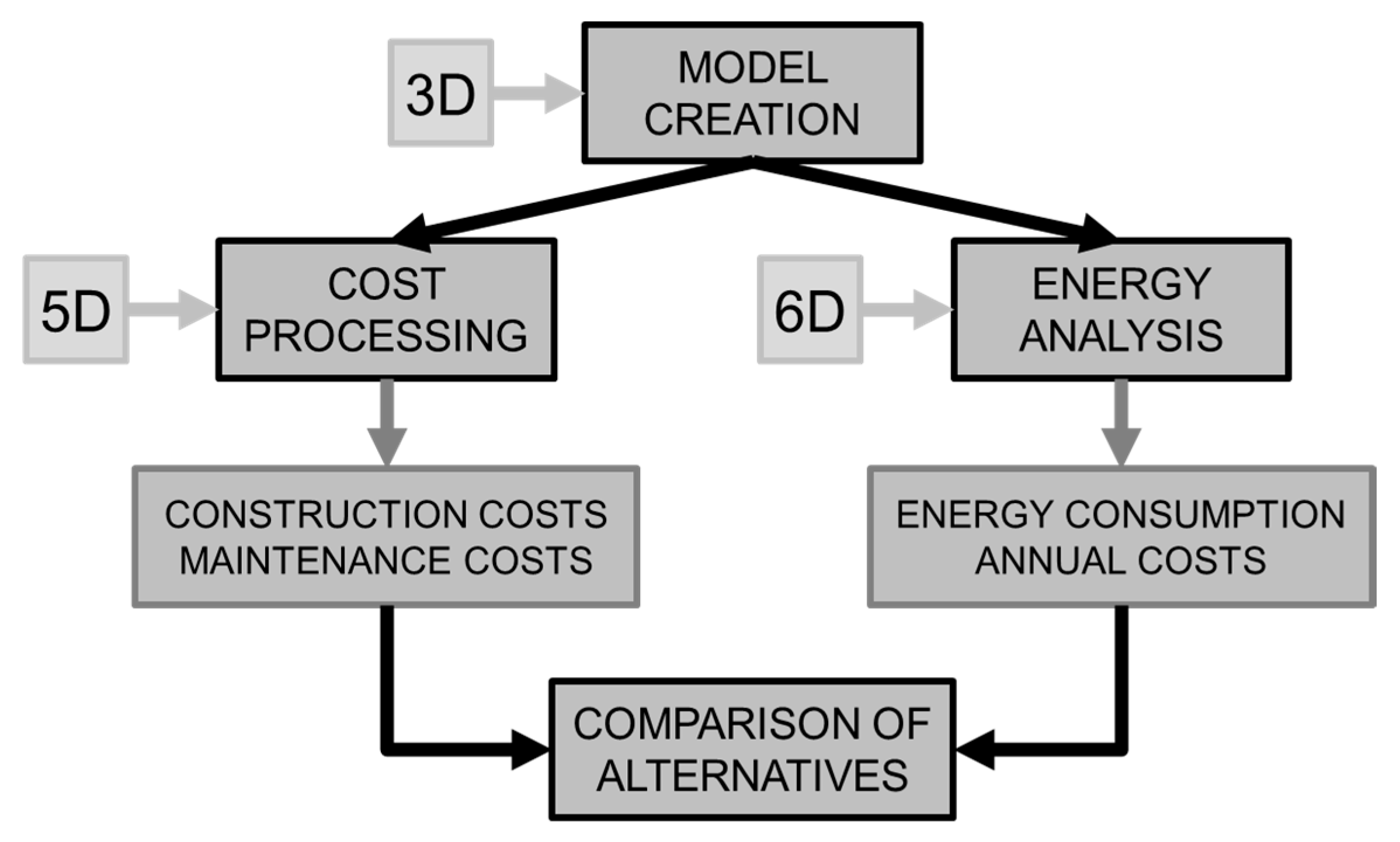
2.1. Modeling Design Alternatives

The proposed approach was tested on the model of a building used as case study, i.e., a realistic architectural project of a single-family house of about 90 m2 designed to accommodate a family of four people. Two possible locations were considered, Milan and Livigno, both in Lombardy, Italy; these geographies are close, and therefore, subject to the same local regulations [26], but are within different climate zones. Climate zones are defined on the basis of the degree days (dd) of a given site, i.e., the sum of the average daily temperature increase needed to achieve a base temperature of 20° throughout the year. In Italy, six climate zones are defined and identified by letters: A (dd < 600), B (600 < dd < 900), C (900 < dd < 1400), D (1400 < dd < 2100), E (2100 < dd < 3000), F (dd > 3000). Milan (2404 dd, Padan plain) is in zone E, while Livigno (4648 dd, central Alps) is in zone F.
The building was modelled with Autodesk Revit 2019, defining its geometry and the different design alternatives from combining different types of the five elements described in the previous section. In particular, for both locations, two types of external/internal walls, roof, slab/floor and windows and three WWRs were considered. For each building component, the less efficient typology was modelled according to D.M. 26 June 2015 (Table 1, Table 2, Table 3 and Table 4) [27], whose requirements in terms of thermal transmittance depend on the climate zone. For this reason, the less efficient alternatives were different for the two locations.
Regarding the modeling of the walls, and in particular, the less efficient type (type 1), the exterior walls were modelled with a load-bearing part made of brick blocks called “Poroton P800”, 25 cm thick, with an overcoat insulation layer. Two plaster layers, both 1.5 cm thick, completed the stratigraphy of the wall. The choice of insulation was made by consulting a green building guide that proposed the use of ecological materials [19]. Specifically, the use of a wood fiber, called “Naturawall” and supplied in the form of plasterable panels was suggested. This overcoat insulation was 10 cm thick for Milan and 12 cm for Livigno. The internal walls were modelled with hollow bricks, 8 cm thick, slightly plastered on the surface. As the second type of exterior walls, a solution with a glulam structure was adopted. Its detailed stratigraphy was as follows: internal finish made of a double plasterboard sheet (2.5 cm thick), an insulated counter wall of 4-cm thickness made of a wooden fiber called “Naturaflex”, a structural part made of glue laminated timber called “XLAM” (9.5 cm thick), overcoat insulation consisting of two different panels, 16 cm of “Naturatherm” and 6 cm of “Naturawall”, a 1.5-cm thick external plaster layer. The corresponding interior walls had a 6-cm thick layer of “Naturaflex” coated with a double plasterboard sheet.
Regarding the roof modeling, a unique construction technique was adopted, properly working on the thickness of the insulating layers to differentiate the different alternatives. As a reference technical solution, a “TORINO” roof type was chosen, as this is quite common in the region where the test was simulated [28]. Starting from the interior side, there was a first layer of 2.5-cm thick wooden planks and a membrane layer consisting of roofing felt which serves as a vapor barrier. Next, two layers of “Naturatherm” insulation with a total thickness of 16 cm for Roof type 1 in Milan, 18 cm for Roof Type 1 in Livigno and 32 cm for Roof type 2 were implemented. This insulation layer was followed by a waterproofing sheath (EPDM membrane), a 5-cm air gap for ventilation and 2.5 cm of brick tiles.
Regarding the floor/slab component, the chosen stratigraphy for the less efficient model is typically adopted in the study region. From the ground, the layers were as follows: a 10-cm thick sand and cement foundation slab, a ventilation layer comprising a plastic igloo of 30 cm in height, a 5-cm thick concrete casting filling, thermal insulation made of expanded polystyrene, 12 cm thick for Milan and 14 cm thick for Livigno, a 5-cm thick of concrete slab, a 19-cm thick sand and cement screed and a 1-cm thick surface finish made of tiles. Floor type 2 modelled the “Foamglas” insulation system [29], i.e., a foundation of sand and cement resting on gravel on which “Foamglas board T4+” panels [30], 20 cm in thickness, were directly placed. Above this insulating layer, the stratigraphy was identical to that of Floor type 1.
The main difference between the two window alternatives was the material of the frame, i.e., aluminum or PVC. The first (Windows type 1) was characterized by higher thermal transmittance, high initial costs but long durability, while the second (Windows type 2) was basically the opposite, and is more popular. For Milan, a double glazing filled with argon gas was chosen; for Livigno, a triple glazing filled by krypton gas was applied. The thermal characteristics of the elements were computed in accordance with UNI EN ISO 10077-1 [31].
Table 1 presents a summary of the modelled building components with a brief description of their differences and the resulting thermal transmittance.
Finally, three different WWRs were defined for analysis: 10%, 20% and 30%. Although WWR is generally defined by external constraints and aesthetic purposes, its impact on the overall building performance, as well as the costs of installation and maintenance, is significant. For this reason, it was decided that this aspect should also be investigated. Figure 3 shows the three different layouts.
Considering all these aspects, a total of 48 models were produced, with each differing in terms of at least one building component or WWR and ready for analysis from the point of view of energy consumption and costs. Table 2 presents a summary of the considered design options.
Information regarding the thermal characteristics of each component was applied to the building model in order to determine the overall thermal transmittances and energy consumption performance to be computed and analyzed. Thermal characteristics were defined on the basis of the technical sheets provided by their manufacturer. The same was done with respect to the costs of installation, to be added to the building component properties for an automatic computation of the initial cost of construction. According to the location of the house under analysis, “Prezzario regionale delle opere pubbliche, ed. 2020” of the Lombardy region was chosen as reference [32]. The values therein were inclusive of materials, labor, equipment rental and other related processing costs. This document was used as a reference for all available processing, while for specialized materials that were not present, quotes from suppliers and companies were considered. Comparing what was available in both the regional price list and supplier quotes, very small differences were found, proving the reliability of the applied approach.

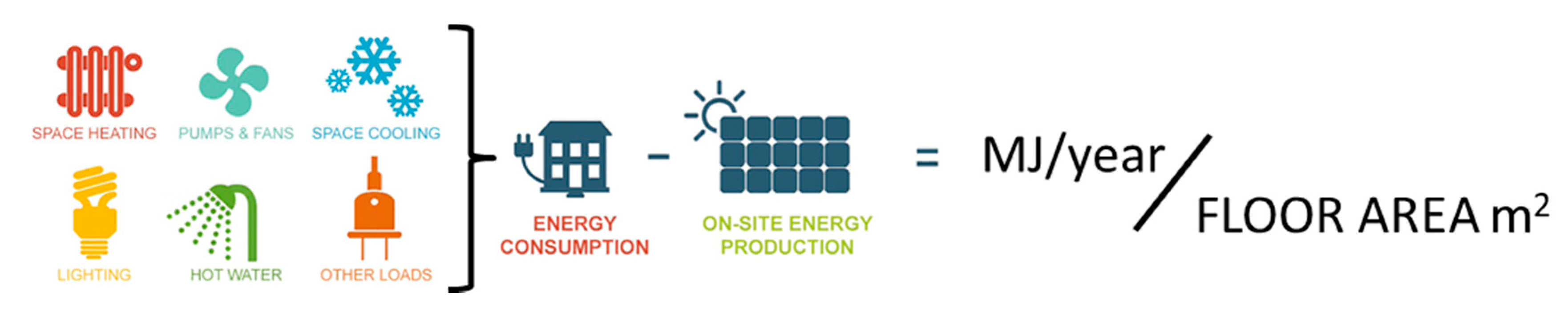
2.2. Energy Analyses of Design Alternatives

Energy analyses were performed with Autodesk Green Building Studio (GBS), but it was necessary to define some preliminary operations and settings for the building models in Revit. First of all, the proper location had to be assigned to each model. Each of the 48 design models was duplicated; the first set was assigned to Milan and the second set to Livigno. The buildings were analyzed under certain assumptions and settings that influence the result. In the presented test, for all the alternatives, the building typology was defined as “Single Family”, operating 24/7, with residential HVAC systems based on a split packaged heat pump with a SEER (Seasonal Energy Efficiency Ratio) of 14 BTU/Wh, with four occupants. Using such parameters, an analytical model was generated and exported via the gbXML format by Revit to the GBS cloud platform. Accessing the website [33], the results of the energy analyses could be consulted. Here, all the assumptions and settings of the model could be verified, as well as the values of the thermal transmittance of each building component used in the model. More importantly, the results were reported in terms of energy consumption, in the form of EUI, electricity and fuel. Once that these energy analyses were performed for all the model alternatives, the obtained EUI and annual energy cost values were examined.

2.3. Cost Processing of the Design Alternatives

The costs of design alternatives in the construction phase were automatically computed with Revit, implementing unitary costs in the models. As stated, the values representing costs can be considered realistic, as they were derived from official pricelists and supplier quotes. Regarding windows, doors and the joists constituting the load-bearing structure of the roof, the costs of supply and installation were the same for each model, while in the case of all the remaining elements, costs per square meter were considered and multiplied by their quantities. This is important, because the thickness of some material can have a big impact on construction costs.
For maintenance costs, two aspects were considered: the economic entity and the frequency of interventions needed to keep the building in good condition, thus guaranteeing the thermal properties assigned to the materials. Regarding the economic entity, the regional price list for public works in the Lombardy region was once again used as a reference [32]. With regard to the frequency with which these operations should be carried out, warranties provided by manufacturers and feedback obtained by interviewed workers were used. Considering a maximum life cycle of 100 years, it was assumed that the following would be required: double plastering for both types of exterior walls after 30 and 70 years in order to prevent the deterioration of the inner insulating layers; for both the types of roofs, a replacement of the waterproof membrane that covers the insulating layer, the wooden joists tiles holders and the damaged brick tiles after 35 and 65 years [34]; for Floor type 1, a complete replacement after 60 years, while no maintenance would be required for Floor type 2, being durable and with better mechanical properties; the replacement of all type 2 windows after 50 years as PVC is a heavy material with low mechanical resistance that undergoes excessive deformation during its life cycle. In Table 3, the costs and frequency of the planned maintenance work are reported.
Regarding usage costs, the annual energy consumption determined through energy analyses was considered, assumed to be constant throughout the whole building life cycle and multiplied by a factor of 0.25 €/kWh for electric supply and 0.03 €/MJ for fuel.

3. Results and Discussion

Once calculated the energy consumption and costs of each design option for each phase of the expected building life cycle, as expressed in Equation (1), the assessment can be done on the basis of these two aspects considered singularly and jointly. In terms of energy consumption, the most efficient option corresponds to that with the lowest EUI, disregarding any assumptions of the building life cycle. In terms of costs, finding the cheapest alternative depends on the expected life cycle, due to the planned maintenance operations and annual energy consumptions. More interesting results can be found computing the IR as expressed in Equations (3) and (4) in order to find the building component which is more worth investing in. In the interests of brevity, a detailed description of the implementation of the proposed approach referring just to the building component “Wall” and the location “Milan” in the construction phase will be provided.

3.1. Example of Evaluation of Design Alternatives

First, the 48 models were divided into two subgroups, each containing models with the same building component typology (Wall type 1 and 2 in the provided example). The mean values of the total costs (at each epoch) and EUIs of the subgroups were then calculated. These averaged values represented a summary of all the combinations containing a given single element. Based on these four values, ∆Ctot and ∆EUI were obtained, and hence, also IR, as their ratio. Figure 4 expresses this concept graphically.
In the construction phase, the average total cost of all the models based on “Wall type 1” was 101,224.93 €, while the computed average energy consumption was 777.4 MJ/m2/year. For models with “Wall type 2”, the corresponding values were 123,375.40 € and 770.2 MJ/m2/year. This means that the more efficient walls yielded an energy saving of 7.2 MJ/m2/year at a cost of 22,150.47 €. The resulting IR for the building component “Wall” in Milan and the construction phase was then 3076.45 €/EUI. Repeating the implementation for all phases of the building’s life cycle and for all the parameters under investigation made it possible to assess the impact of investing in a given building component.
The same process can be applied to more than one building component, as shown in Figure 5 in the case of two components under simultaneous assessment.
In this case, the subgroups were smaller and contained only models with both components of the same typology. For instance, in case of assessment of the “Walls” and “Roof” building components, only models containing Walls type 1 and Roof type 1 were considered, as well as for type 2 models, for a total of 24 models out of the 48 available ones. During construction, the type 1 combination had an average EUI of 780.8 MJ/m2/year with an average total cost of 97,844.25 €, while the type 2 combination had values of 766.8 MJ/m2/year and 126,756.08 €. The resulting IR was then 2065.13 €/EUI. The computation and comparison of the investment ratios for both the Milan and Livigno cases, during all phases of an expected life cycle of 100 years and for both single and double building components, provided a broad overview of all design alternatives, making it easier to find the optimal solution.

3.2. Analyses of Costs and Energy Consumption of the Design Alternatives

Some preliminary considerations should be noted about the WWRs that were investigated. As shown in Figure 6, an increase in construction costs, due to the presence of a higher number of windows, always corresponds to an increase in consumption, since the U-values of the windows are consistently higher than those the walls; this result is obviously time and space independent. Therefore, the following considerations are valid for both the Milan and Livigno cases, and for any considered life cycle. Considering the two windows typologies separately, by adopting the most efficient windows the impact of changing WWR decreases significantly, but never in such a way as to show a reverse trend, making this parameter unmeaningful in the proposed approach, also considering the fact that WWR is usually set by external constraints (aesthetic or regulations).
As far as the other four components under analysis are concerned, in Figure 7, Figure 8, Figure 9 and Figure 10, energy consumption and total costs are reported for both mild and cold climate zones (Milan and Livigno, respectively) and for different considered life cycles (0, 50 and 100 years, respectively) in order to be able to analyze them separately.
In terms of energy consumption (Figure 7), it can be noted that adopting more efficient building components leads to different energy savings depending on the type of climate. Disregarding the fact that the expected energy consumption in a milder climate is lower, in Milan, for all the building components, the energy saving was similar, i.e., roughly 2%. On the other hand, in Livigno, the impact is greater and differences between building components are clearly visible, with the more efficient walls obtaining improvements of up to roughly 4%, despite the minimum requirements for Livigno being higher, as explained in the previous paragraph.
In terms of total costs in the construction phase (Figure 8), in both the locations, they were pretty similar. This is an expected result, because during construction, the costs due to usage and energy consumption are null, making them climate independent. Note that for windows, the more efficient ones lead to a negative ∆Ctot, and the other building components have very different positive ∆Ctot, i.e., roughly between 5% (Floor) and 22% (Walls) additional costs.
Considering a longer life cycle, the impact on cost of choosing different building components becomes significant (Figure 9). First of all, the total costs in Livigno are almost 15% higher than in Milan due to the higher yearly energy demand. Second, more efficient windows have no more negative ∆Ctot due to required maintenance operations on Window type 1. Third, more efficient building components lead to a smaller costs increase in colder climates, justifying the greater initial expense, even with the roof obtaining a negative ∆Ctot.
Considering an even longer building life cycle, the results for the two locations are definitely different from one another (Figure 10). More efficient floors lead to cost savings in both locations, but in Milan, this saving is negligible if more efficient (and more expensive) walls are chosen.

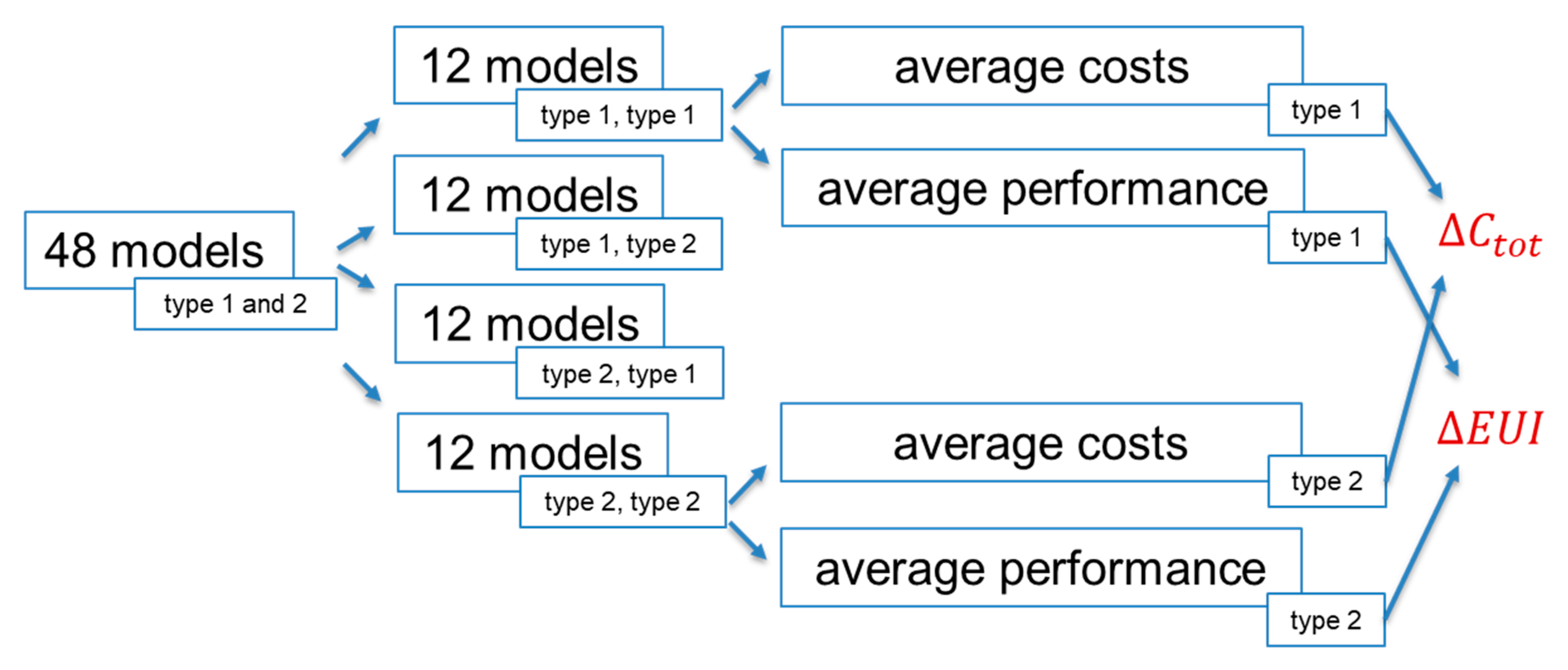
3.3. Joint Analyses of Costs and Energy Consumption of Design Alternatives

The reported analysis on the estimated energy consumption and total costs show how important a joint analysis can be, taking into account both these aspects simultaneously. Furthermore, the same analysis can lead to different results depending on the location of the building, the considered life cycle and interactions among the building components. For this reason, analyzing the IR can be a more efficient way for assessing the best design alternatives, providing a more complete overview of the impact of each of them in terms of economic convenience while targeting a more efficient building. Figure 11 shows the IRs computed for each building component according to time, in both Milan and Livigno.
From these graphs, it can be seen that the computed IRs for the Milan case study are almost one order of magnitude greater than those for Livigno. This means that choosing more efficient building components is, in general, much more economical, as the climate in the latter setting is more extreme. In some way, this may be considered obvious, because greater energy demands will give rise to greater potential energy efficiency among the design alternatives, justifying a more expensive construction. Furthermore, the slopes of the reported IRs are negative due to the influence of Cu that makes more efficient solutions more economical for longer life cycles. Sudden discontinuities are evident when maintenance operations are expected; these “jumps” can be upward when the operations are on the more efficient component typologies or downward when carried out on the less efficient ones. Null values represent negative IRs; in these cases, the more efficient solution is also the cheapest one, immediately providing the answer regarding which building component is worth investing in. On the basis of these considerations, this analysis will now focus only on the case study in Livigno; this is for brevity, as the analysis is replicable with the Milan model. Table 4 reports numerically what is expressed in Figure 11b (rounding the IRs to the nearest integer), making it simple to identify the four possible scenarios.
For life cycles of up to 35 years, investing first in PVC windows is the best choice, since this solution is less expensive and provides better energy performance. Regarding the other building components, a smaller IR is always obtained by the roof. In fact, after 35 years of usage, choosing the most efficient typology gives rise to additional costs, i.e., ∆Ctot of 288.45 €, but leads to an energy saving ∆EUI of 24.4 MJ/m2/year with a resulting IR of 11.83 €/EUI. Then, for an expected life cycle of less than 35 years, the investments should be made following the order: windows, roof, walls and floor.
For life cycles of up to 45 years, both more efficient windows and roof typologies would be the best choice. Longer usage of a more efficient roof can compensate for the initial bigger investment, justifying the choice of this alternative. Regarding the other building components, a smaller IR is obtained by the walls. In fact, after 45 years of usage, the more efficient typology gives rise to additional costs ∆Ctot of 11,832.26 €, but leads to an energy saving ∆EUI of 41.3 MJ/m2/year with a resulting IR of 286.50 €/EUI. Then, for an expected life cycle of between 35 and 45 years, the investments should be made following the order: indifferently for windows or roof and then walls and floors.
For an expected life cycles of 55 years, the planned maintenance operations on the more efficient windows mean that they are no longer the most economical building component. For such a life cycle, only the more efficient roof justifies the initial investment. A smaller IR is then obtained by walls, while floors and windows get a bigger and almost equal the IR. In fact, after 55 years of usage, choosing the more efficient wall typology leads to additional costs, i.e., ∆Ctot of 9711.58 €, but offers an energy saving of ∆EUI of 41.3 MJ/m2/year with a resulting IR of 235.15 €/EUI. Therefore, for an expected life cycle of 45–55 years, the investments should be made initially on roofs, followed by walls and then, indifferently for windows or floors.
For life cycles of up to 100 years, the initial investments on more efficient roofs and floors are totally justified. This is due to the fact that planned maintenance operations on the less efficient floor and the inferior thermal properties of the less efficient roof make them economically unviable. A smaller IR is then obtained again by walls. In fact, after 100 years of usage, choosing the more efficient wall typology gives rise to additional costs ∆Ctot of 170.23 €, but to an energy saving ∆EUI of 41.3 MJ/m2/year with a resulting IR of 4.12 €/EUI. As such, for an expected life cycle of up to 100 years, the investments should be made first and indifferently for roofs and floors, followed by walls and then for windows.
The previous analyses were conducted on the basis of the schema presented in Figure 4, considering a single building component at a time. In order to verify whether the results could be confirmed considering two parameters simultaneously, the same approach was implemented following the schema presented in Figure 5. Table 5 presents the results numerically (rounding the IRs to the nearest integers).
For life cycles of up to 35 years, once it had been clarified that the more efficient windows were the best choice and that the worst IR was obtained by a combination of more efficient walls and floors, comparing the IRs obtained by the roof when combined with walls or floor, the latter seems to be preferable. Then, the sequence with the best design alternatives is the one investing in windows, roofs, floors and walls.
For life cycles of between 35 and 45 years, only the combination of more efficient walls and floors obtains a positive IR. Then, once it has been clarified that investing first in windows and roofs is the best choice, there is not prescribed sequence regarding walls and floors.
For life cycles of 45–55 years, the worst IR is obtained by the combination of floor and windows, while combinations considering roofs are always the best choice, and the combination of walls and floors yielded the minimum positive IR. This leads us to conclude that for such a building life cycle, it would advantageous to invest in roofs, walls, floors and finally windows.
For longer life cycles, i.e., up to 100 years, only the combination of walls and windows obtains positive IRs. This means that roofs and floors are the building components to invest in firstly, followed by walls and windows.
These two approaches showed slightly different results that should at least taken into account. In the first scenario (0–35 years), the two less economical building components, i.e., walls and floors, behaved differently if considered separately or jointly. If considered separately, walls were the first building component worth investing in, after windows and roofs. If considered jointly, floors seem to be more economical. This is an unexpected result; while confirming the validity of investing first in more efficient windows and roofs, regarding the other two components, it is not clear which is more economical. In the second scenario (35–45 years), the two approaches led to the same conclusions, with the first showing that walls are a better choice than floors. In the third scenario, the second approach clearly indicates that floors are more worth investing in than windows. Finally, comparing the two approaches for the longest expected life cycle, roofs and floors remained the two best alternatives for prioritized investment, with windows being the last choice.
Table 6 presents a summary of the results of both analyses, showing the building components which are more worth investing initially.

4. Conclusions

Summarizing the results obtained with the proposed approach, interesting conclusions can be drawn. A first consideration can be made about climate; as already seen in previous studies [4,20,21], this parameter showed a great influence on energy consumption. What was not obvious was its impact on costs. Thanks to the fact that the limitations imposed by regulations were taken into account, it was possible to assess the economic impact of the improvement of the building components considering different climates. In fact, for more extreme climates, an improvement in energy performance, compared to solutions with limited characteristics imposed by regulations, leads to considerable savings over time. For milder climates, the possibility of improving the thermal characteristics of the dwelling did not lead to significant advantages from an economic point of view. This result was obtained on the basis of a hypothetical structure fulfilling at least the minimum requirements imposed by regulations, but, in the case of pre-existing, old and obsolete structures, the return on the investment for a renovation could be analyzed in the same manner.
Another important consideration is the alternatives that provide the best investment ratio values. This has a great dependency on the expected life cycle of a building, and what could seem to be economical in one case could be far from being the best alternative in a different setting. This strengthens the benefits provided by the proposed approach.
The proposed approach was implemented taking into account several building components, defining the set of design alternatives, and was based on updated and official quotations. By modifying the number and typology of building components, as well as the shape of the building or the pricelists, such an approach has general validity and can be easily replicated. It is robust to changes, making it a valid tool for preliminary assessments of environmental and cost sustainability analyses. With respect to previous studies aiming at optimizing environmental benefits and economic investment [11,22,23], the proposed approach also considers the maintenance operation costs that, depending on the expected life cycle of the building, can lead to different results. In fact, the obtained results showed that this variable must be taken into account for realistic cost-benefit analyses. Once the project budget has been fixed, more informed decisions can be made, taking into account the different returns that a given design option could offer.
As far as possible future studies are concerned, it might be interesting to investigate aspects related to the time factor, i.e., the fourth dimension of BIMs. This is because the timing of the realization of each design alternative differs, generating advantages or disadvantages that a designer should take into account. In fact, some building typologies are quicker to realize, making them preferable for the simplicity of installation as well as for the reduction of the total construction costs, due to the reduced timetable.

Author Contributions

Conceptualization, C.I.D.G., A.M. and P.P.; methodology, C.I.D.G., A.M. and P.P.; software, A.M. and P.P.; validation, A.M. and P.P.; formal analysis, C.I.D.G., A.M. and P.P.; investigation, A.M. and P.P.; resources, A.M. and P.P.; data curation, A.M. and P.P.; writing—original draft preparation, C.I.D.G.; writing—review and editing, C.I.D.G., A.M. and P.P.; visualization, C.I.D.G., A.M. and P.P.; supervision, C.I.D.G. All authors have read and agreed to the published version of the manuscript.

Funding

This research received no external funding.

Conflicts of Interest

The authors declare no conflict of interest.

References

  1. Najjar, M.K.; Tam, V.W.Y.; Di Gregorio, L.T.; Evangelista, A.C.J.; Hammad, A.W.A.; Haddad, A. Integrating parametric analysis with building information modeling to improve energy performance of construction projects. Energies 2019, 12, 1515. [Google Scholar] [CrossRef] [Green Version]
  2. Sözer, H.; Sözen, H. Waste capacity and its environmental impact of a residential district during its life cycle. Energy Rep. 2020, 6, 286–296. [Google Scholar] [CrossRef]
  3. Zardo, P.; Ribeiro, L.A.; Mussi, A.Q. BIM and parametric design applications for buildings’ energy efficiency: An analysis of practical applications. Arquitetura Rev. 2019, 15, 238–255. [Google Scholar]
  4. Sadeghifam, A.N.; Meynagh, M.M.; Mahdiyar, M.; Memari, A.; Ismail, S.; Tabatabaee, S. Assessment of the building components in the energy efficient design of tropical residential buildings: An application of BIM and statistical Taguchi method. Energy 2019, 188, 116080. [Google Scholar] [CrossRef]
  5. Palumbo, E.; Politi, S. Possible Integration Approaches of Life Cycle Assessment in Bim; Laura, M., Mussinelli, E., Tucci, F., Eds.; Maggioli Editore: Milano, Italy, 2019; ISBN 9788-8-916-3602-7. [Google Scholar]
  6. Soust-Verdaguer, B.; Llatas, C.; García-Martínez, A. Simplification in life cycle assessment of single-family houses: A review of recent developments. Build. Environ. 2016, 103, 215–227. [Google Scholar] [CrossRef] [Green Version]
  7. Soust-Verdaguer, B.; Llatas, C.; García-Martínez, A. Critical review of BIM-based LCA method to buildings. Energy Build. 2017, 136, 110–120. [Google Scholar] [CrossRef]
  8. Hollberg, A.; Genova, G.; Habert, G. Evaluation of BIM-based LCA results for building design. Autom. Constr. 2020, 109, 102972. [Google Scholar] [CrossRef]
  9. Raut, A.; Khatoon, S.; Goud, P. A comparative study on effects of various insulating layers of roof system on energy usage of building envelope. IOP Conf. Ser. Earth Environ. 2019, 354, 012055. [Google Scholar] [CrossRef]
  10. Jalilzadehazhari, E.; Vadiee, A.; Johansson, P. Achieving a trade-off construction solution using BIM, an optimization algorithm, and a multi-criteria decision-making method. Buildings 2019, 9, 81. [Google Scholar] [CrossRef] [Green Version]
  11. Sandberg, M.; Mukkavaara, J.; Shadram, F.; Olofsson, T. Multidisciplinary optimization of life-cycle energy and cost using a bim-based master model. Sustainability 2019, 11, 286. [Google Scholar] [CrossRef] [Green Version]
  12. Singh, P.; Sadhu, A. Multicomponent energy assessment of buildings using building information modeling. Sustain. Cities Soc. 2019, 49, 101603. [Google Scholar] [CrossRef]
  13. Spiridigliozzi, G.; Pompei, L.; Cornaro, C.; De Santoli, L.; Bisegna, F. BIM-BEM support tools for early stages of zero-energy building design. IOP Conf. Ser. Mater. Sci. 2019, 609, 072075. [Google Scholar] [CrossRef]
  14. Tallberg, M.; Bohne, R. BIM based iterative simulation—Efficient building design: A case study. IOP Conf. Ser. Earth Environ. 2019, 323, 012043. [Google Scholar] [CrossRef]
  15. Akcay, E.C.; Arditi, D. Desired points at minimum cost in the “Optimize Energy Performance” credit of LEED certification. J. Civ. Eng. Manag. 2017, 23, 796–805. [Google Scholar] [CrossRef]
  16. Veselka, J.; Nehasilová, M.; Dvořáková, K.; Ryklová, P.; Volf, M.; Růžička, J.; Lupíšek, A. Recommendations for developing a BIM for the purpose of LCA in green building certifications. Sustainability 2020, 12, 6151. [Google Scholar] [CrossRef]
  17. Palumbo, E.; Soust-Verdaguer, B.; Llatas, C.; Traverso, M. How to obtain accurate environmental impacts at early design stages in BIM when using environmental product declaration. A method to support decision-making. Sustainability 2020, 12, 6927. [Google Scholar]
  18. Montiel-Santiago, F.J.; Hermoso-Orzáez, M.J.; Terrados-Cepeda, J. Sustainability and energy efficiency: BIM 6D. Study of the BIM methodology applied to hospital buildings. Value of interior lighting and daylight in energy simulation. Sustainability 2020, 12, 5731. [Google Scholar] [CrossRef]
  19. Ijasahmed, M.; Ramesh Krishnan, L.; Gangadhara Kiran Kumar, L. Modeling and simulation of a building towards energy efficiency. Int. J. Innov. Tech. Exp. Eng. 2019, 8, 1063–1073. [Google Scholar]
  20. Maciel, A.C.F.; Carvalho, M.T. Operational energy of opaque ventilated façades in Brazil. J. Build. Eng. 2019, 25, 100775. [Google Scholar] [CrossRef]
  21. Mirrahimi, S.; Mohamed, M.F.; Haw, L.C.; Ibrahim, N.L.N.; Yusoff, W.F.M.; Aflaki, A. The effect of building envelope on the thermal comfort and energy saving for high-rise buildings in hot–humid climate. Renew. Sustain. Energy Rev. 2015, 53, 1508–1519. [Google Scholar] [CrossRef]
  22. Zachariadis, T.; Michopoulos, A.; Vougiouklakis, Y.; Piripitsi, K.; Ellinopoulos, C.; Struss, B. Determination of cost-effective energy efficiency measures in buildings with the aid of multiple indices. Energies 2018, 11, 191. [Google Scholar] [CrossRef] [Green Version]
  23. Astiaso Garcia, D.; Cumo, F.; Tiberi, M.; Sforzini, V.; Piras, G. Cost-benefit analysis for energy management in public buildings: Four Italian case studies. Energies 2016, 9, 522. [Google Scholar] [CrossRef]
  24. ASHRAE. Available online: https://www.ashrae.org/ (accessed on 29 July 2020).
  25. Shang-yuan, C. A green building information modelling approach: Building energy performance analysis and design optimization. MATEC Web Conf. 2018, 169, 01004. [Google Scholar]
  26. Gazzetta Ufficiale della Repubblica Italiana, Presidenza della Repubblica, D.P.R. 26/08/1993, n. 412: Regolamento Recante Norme per la Progettazione, L’installazione, L’esercizio e la Manutenzione Degli Impianti Termici Degli Edifici ai Fini del Contenimento dei Consumi di Energia. Available online: https://www.gazzettaufficiale.it/eli/id/1993/10/14/093G0451/sg (accessed on 2 September 2020).
  27. Gazzetta Ufficiale della Repubblica Italiana, Ministero dello Sviluppo, D.M. 26/06/2015: Applicazione delle Metodologie di Calcolo Delle Prestazioni Energetiche e Definizione Delle Prescrizioni e dei Requisiti Minimi Degli Edifici. Available online: https://www.gazzettaufficiale.it/eli/id/2015/07/15/15A05198/sg (accessed on 2 September 2020).
  28. Guida alla Bioedilizia 2020/21. Available online: https://naturalia-bau.it/ (accessed on 29 July 2020).
  29. Foamglas. Available online: https://www.foamglas.com/it-it (accessed on 29 July 2020).
  30. Foamglas Product Sheet—FOAMGLAS® BOARD T4+. Available online: https://www.foamglas.com/it-it/prodotti/fgbt4boards (accessed on 29 July 2020).
  31. UNI EN ISO 10077-1:2018: Prestazione Termica di Finestre, Porte e Chiusure Oscuranti—Calcolo Della Trasmittanza Termica—Parte 1: Generalità. Available online: http://store.uni.com/catalogo/index.php/catalog/product/view/id/274678/s/uni-en-iso-10077-1-2018/category/3440/?___store=en&josso_back_to=http%3A%2F%2Fstore.uni.com%2Fjosso-security-check.php&josso_cmd=login_optional&josso_partnerapp_host=store.uni.com&___from_store=it (accessed on 2 September 2020).
  32. Regione Lombardia: Prezzario Regionale Delle Opere Pubbliche 2020. Available online: https://www.regione.lombardia.it/wps/portal/istituzionale/HP/DettaglioServizio/servizi-e-informazioni/Enti-e-Operatori/Autonomie-locali/Acquisti-e-contratti-pubblici/Osservatorio-regionale-contratti-pubblici/prezzario-lavori-opere-pubbliche/prezzario-opere-pubbliche (accessed on 2 September 2020).
  33. Autodesk Green Building Studio. Available online: https://gbs.autodesk.com/ (accessed on 29 July 2020).
  34. Illankoon, I.M.C.S.; Tam, V.W.Y.; Le, K.N.; Wang, X.; Wang, J. Optimal roofing solutions for Australian green buildings: A life-cycle cost perspective. In Engineering Sustainability, Proceedings of the Institution of Civil Engineers—Engineering Sustainability; ICE Publishing: London, UK, 2020; Volume 173, pp. 1–2. [Google Scholar]
Figure 1. General workflow of the proposed approach for assessments of design alternatives.
Sustainability 12 07507 g001
Figure 2. Schematic representation of the definition of the Energy Use Intensity.
Sustainability 12 07507 g002
Figure 3. Layouts of the modelled building for different WWRs.
Sustainability 12 07507 g003
Figure 4. Schematic representation of the approach for IR computation considering a single building component.
Sustainability 12 07507 g004
Figure 5. Schematic representation of the approach for IR computation considering two building components simultaneously.
Sustainability 12 07507 g005
Figure 6. Impact on construction costs and energy consumption according to WWR.
Sustainability 12 07507 g006
Figure 7. Energy consumption comparison according to building component typologies.
Sustainability 12 07507 g007
Figure 8. Construction cost according to building component typologies.
Sustainability 12 07507 g008
Figure 9. Total costs after 50 years according to building component typologies.
Sustainability 12 07507 g009
Figure 10. Total costs due after 100 years according to building component typologies.
Sustainability 12 07507 g010
Figure 11. IR according to building life cycle in the Milan (a) and Livigno (b) cases.
Sustainability 12 07507 g011
Table 1. Summary of the building component typologies with a brief description of the main differences and their corresponding thermal properties.
Building ComponentTypeSiteBrief DescriptionU [W/m2K]
Wall1Milan10 cm single overcoat0.26
1Livigno12 cm single overcoat0.23
2Milan, Livigno16 + 6 cm double overcoat0.13
Roof1Milan16 cm insulating layer0.22
1Livigno18 cm insulating layer0.20
2Milan, Livigno32 cm insulating layer0.11
Floor1Milan12 cm insulating layer (Polystyrene)0.26
1Livigno14 cm insulating layer (Polystyrene)0.24
2Milan, Livigno20 cm insulating layer (Foamglas)0.19
Window1MilanAluminum, double glazing, Argon gas1.40
1LivignoAluminum, triple glazing, Krypton gas1.10
2MilanPVC, double glazing, Argon gas1.20
2LivignoPVC, triple glazing, Krypton gas0.90
Table 2. Summary of the model alternatives based on combinations of WWR and building components.
Model #12345678910111213141516
Wall Type1111111111112221
Roof Type1111111112221111
Floor Type1111112221111112
Window Type1112221111111112
WWR Type1231231231231231
Model #17181920212223242526272829303132
Wall Type1111122211122222
Roof Type1122211122211122
Floor Type2211111122222211
Window Type2222222211111111
WWR Type2312312312312312
Model #33343536373839404142434445464748
Wall Type2111222222222222
Roof Type2222111222222222
Floor Type1222222111222222
Window Type1222222222111222
WWR Type3123123123123123
Table 3. Planned maintenance. The cost for Windows type 2 replacement is not reported as it is slightly different for Milan and Livigno.
Building ComponentMaintenance DescriptionCost
[€/m2]
Schedule [Years]
Walldouble plastering9.0830–70
Roofreplacement of the waterproof membrane, joists tiles holders, damaged tiles20.0535–65
Floor type 1full replacement208.5160
Windows type 2full replacementn/a50
Table 4. IR according to building life cycle in the Livigno case.
YearsWalls [€/EUI]Roof [€/EUI]Floor [€/EUI]Windows [€/EUI]
0517242695-
5492209662-
10466176629-
15440143597-
20414110564-
2538977531-
3036344498-
3533711465-
40312-432-
45286-399-
50260-366366
55235-333333
60209--300
65183--267
70158--234
75132--201
80106--169
8581--136
9055--10
9529--70
1004--37
Table 5. IR according to building life cycle in the Livigno case and considering two building components simultaneously.
YearsWalls
Roof
[€/EUI]
Walls
Floor
[€/EUI]
Walls
Windows
[€/EUI]
Roof
Floor
[€/EUI]
Roof
Windows
[€/EUI]
Floor
Windows
[€/EUI]
0415560-401--
5387533-368--
10358505-335--
15330478-302--
20301451-269--
25273423-236--
30245396-203--
35216368-170--
40-341----
45-313----
50-286290--366
55-259262--333
60--235---
65--207---
70--179---
75--152---
80--124---
85--96---
90--68---
95--41---
100--13---
Table 6. Sequence of the building components which are more worth investing in. The “/” represents an ambiguity regarding the choice of the best component.
YearsSingle Component AnalysisDouble Component Analysis
0–35Windows, Roof, Walls, FloorWindows, Roof, Floor, Walls
35–45Windows/Roof, Walls, FloorWindows/Roof, Walls/Floor
45–55Roof, Walls, Windows/FloorRoof, Walls, Floor, Windows
55–100Roof/Floor, Walls, WindowsRoof/Floor, Walls/Windows

