1. Introduction
The exploitation of sustainability energy is essential for guaranteeing an energy supply of human society [
1,
2]. As one of the most mature, sustainable and clean source of energy, hydropower is widely applied around the world. With the development of sustainablity energy, the proportion of hydropower in the power grid is increasing rapidly, while the proportion of unsustainable energy, such as thermal power, is decreasing [
3]. The rapid change of operating conditions makes it difficult to maintain the stability of hydro-dominant power system [
4]. As a result, the sustanable operation of human society requires for more comprehensive security measures of stable power system.
One of the prominent problems faced with hydro-dominant power system is ultra-low-frequency oscillation (ULFO) with a frequency deviation of 0.1 Hz lower, which is caused by the negative damping of hydro generators. ULFO might lead to an oscillation of all generators with the same oscillation frequency, restricting consumption of hydropower renewable energy.
In fact, the ULFO phenomenon has been observed in power systems all over the world. In a Turkish power system, oscillations with frequency deviation of about 0.05 Hz were observed [
5]. In 2008, the ULFO occurred in Colombia power grid when the proportion of hydropower was increased [
6], and the oscillation lasts about 20 s. In 2012, there was an abnormal frequency fluctuation in JinSu DC Island test in China, with a period of about 14 s and an amplitude of ±0.26 Hz [
7]. On 23 January 2015, there was an ULFO with an oscillation period of 13 s and an oscillation frequency of about 0.08 Hz, lasting for about 4 min. After the trip of the Tibetan Wooden unit, the frequency of the Tibetan middle power grid exceeded the low-frequency load-shedding limit [
8]. In the 2016 asynchronous networking test of Yunnan power grid (YNPG), long-term and large-amplitude ULFO also occurred with an oscillation period of about 20 s and an amplitude of ±0.1 Hz lasting for nearly half an hour. It posed a major threat to the safe and stable operation of YNPG after asynchronization [
9]. The asynchronous operation of the Southwest China Power Grid (SCPG) faced with an obvious risk of ULFO according to the simulation. The governor parameters optimization [
10] and the DC frequency limit control (FLC) are adopted to suppress it. The asynchronous operation test of SCPG verifies the effectiveness of the strategy.
In fact, the ULFO is not a new problem in the power system. In the early stage of the power system development, there are cases of ULFO in the local power grid with isolated load or dominated by hydropower. P Kundur discovered this problem as early as the 1970s and 1980s and analyzed it. It was pointed out that an over-fast adjustment of the speed control system will produce negative damping within the ultra-low-frequency band, so it is necessary to carefully adjust the governor parameters [
11,
12]. However, with the development of thermal power and the synchronous interconnection of power grid, the ULFO has not been the focus of academic and industrial circles for a long time. No research or technical reserve has been built. When the ULFO occured in the asynchronous operation test of YNPG, the dispatchers had no clear means to quell the oscillation, so they could only try to find the effective control method by trial and error [
13].
With the continuous occurrence of ULFO events, the mechanism, characteristics and control strategy of ULFO have become a research hotspot. In terms of mechanism and characteristics, the relevant research mainly analyzes the causes and main influencing factors from the aspects of eigenvalue analysis [
14], parameter sensitivity [
15,
16] and damping torque coefficient [
17,
18]. In terms of control strategy, the research mainly focuses on the means of governor parameter optimization and adjustment [
7,
19,
20], introduction of frequency limit control (FLC) of HVDC [
21,
22], and the means of optimizing PSS parameters or using governor additional control [
23,
24] to suppress ULFO, but it has not yet been applied.
For the hydropower grid that SCPG and YNPG represent, there is no clear standard or requirement for the level to which the ULFO damping needs to be raised when formulating the ULFO suppression strategy. As the ULFO period is distinctly longer than the low-frequency oscillation, the existing low-frequency oscillation dynamic damping control index can not be directly adopted as the guide of the ULFO control. The lack of guiding foundation for the oscillation analysis in the operation of a practical power system requires for a specific index, based on which the control strategy and the damping control are designed. Simulation analysis has shown that the range and strategy of governor parameter optimization and adjustment are significantly different according to different damping control indexs.
In this paper, the main influencing factors of the ULFO are analyzed, and the key factors affecting the amplitude and damping are further clarified. A damping control standard adaptable to the ULFO in hydro-dominant power system is proposed. With the proposed index, control strategy of ULFO can be designed, avoiding the occurrence of oscillation or conservative strategy due to unclear indicators, which might reduce the consumption capacity and limit the sustainablility development of hydropower.
The rest of this paper is organized as follows.
Section 2 analyzes the mechanism and control strategy of ULFO.
Section 3 designs damping control index for ULFO.
Section 4 verifies the proposed index. Conclusions derived from these analyses are presented in
Section 5.
2. Mechanism and Control Strategy of ULFO in Hydropower Dominant Power Grid
2.1. The Inevitability of the ULFO in Hydropower Dominant Power Grid
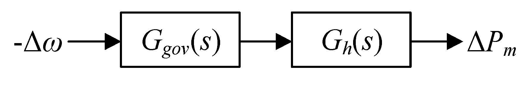
The open-loop system model of a governor and a turbine can be expressed in
Figure 1. The model of the most commonly used governor and turbine are detailed in the
Appendix A.
The open-loop transfer function of the governor and turbine system in
Figure 1 can be expressed as:
Decomposing (3) in the Δ
δ–Δ
ω coordinate system, mechanical power
deviations of a governor can be expressed in terms of its speed
ω and angle
δ deviations, known as damping and synchronizing torque, respectively [
25].
where
(p.u./rad/sec) and
(p.u.) are damping and synchronizing coefficients, respectively.
With the open-loop transfer function of hydro turbine governor, the damping coefficient at frequency f is obtained by substituting the Lagrange operator into (6). The physical meaning of is that it is the projection of mechanical torque on the axis, indicating the magnitude of the damping torque. When > 0, the turbine governing system provides positive damping to the system.
With the typical parameters, the governing system of the hydropower unit provides negative damping in the ultra-low-frequency range, as shown in
Figure 2.
Figure 2 illustrates that as the water starting time Tw increases, the damping coefficient is of large negative values in the ultra-low-frequency band of [0–0.1] Hz. The water starting time Tw usually varies with different load, penstock and hydraulic head. However, regardless of Tw values, the damping coefficients are always negative, which means the damping of whole system increases with the primary frequency regulation system being taken out [
26].
2.2. Analysis of Influencing Factors
The influence of key parameters such as time constant of water hammer effect and PID parameter of governor on ULFO has been analyzed in detail by root locus, parameter sensitivity and other methods [
9,
10,
11,
12,
13]. The simulation text further shows that the damping and amplitude of the ULFO are closely related to the disturbance form, unit parameters and operation mode of the power grid. This section takes an actual power system of sending plant as an example to build a single power plant with load model, as shown in
Figure 3. The generator G1–G4 adopts a typical 8-type governor model and parameters according to field tests. The N-1 fault at transmission line can excites ULFO. This section analyzes the generator inertia time constant, the governor frequency input limit in the governor model and the output limit of water turbine to further clarify their influence on amplitude of ULFO.
2.2.1. Inertia Time Constant
Set the inertia time constant Tj to be two times and a half of the original value respectively. Simulation results considering different Tjs are shown in
Figure 4. It can be seen that at the beginning of the fault, the oscillation is of negative damping. After that, it becomes to equal amplitude oscillation. The larger Tj is, the smaller the amplitude of ULFO becomes.
2.2.2. Governor Frequency Input Limiting
The frequency input limitation shown in
Figure A1 is used to restrict the input frequency deviation and ensure the safety of turbine unit. Set the governor frequency input limiting Max/Min to be ±0.1, ±0.15, and ±0.2 Hz, respectively; the simulation results are shown in
Figure 5. It can be seen that at the beginning of the fault, the amplitude oscillation still appears, and then it turns to equal amplitude oscillation, and the higher the frequency input limit, the greater the amplitude of ULFO.
2.2.3. Mechanical Power Output Limiting
The output limitation shown in
Figure A2 is used to restrict the output of hydroturbine. Set the water turbine output limiting Pmax (unit value) to be 1.01, 1.05 and 1.1, respectively; the simulation results are shown in
Figure 6. It can be seen that the higher the frequency output limiting, the higher the governor’s participation in the ULFO, and the greater the amplitude of the ULFO.
2.3. Control Measures of ULFOs in Hydro-Dominant Power Systems
There are three ways to control the ULFO in hydro-dominant power systems:
(1) From a perspective of increasing the positive damping level of the system, adjusting the operation mode and increasing the capacity of the thermal power, which provies positive damping on ULFOs, can be adopted. The advantage is that it does not affect the frequency regulation capacity of the power grid. However, increasing the thermal power is not conducive to the consumption of sustainability hydropower energy. The feasibility is relatively low under the current situation, which requires energy conservation, emission reduction and a large amount of clean energy.
(2) From a perspective of reducing the negative damping provided by the hydropower unit, the PID parameters optimization of the governor of hydro unitcan be adopted. The advantage of this method is that the ULFO can be damped without affecting the operation mode of power system. However, the optimization of governor parameters usually leads to weaken the system frequency regulation ability. Therefore, it is necessary to achieve a balance between suppressing the ULFO and maintaining the frequency regulation ability.
(3) In addition, the positive damping also can be increased by using HVDC modulation, such as FLC. The advantage by using FLC is that it canstrengthen the frequency modulation ability of system. However, due to the limited number of HVDC, the control measures will be greatly weakend when HVDC maintenance or shutdown because of contingency.
In general, the parameter optimization of governors is the most common and effective method in a practical power system. For regional or provincial power grids dominated by hydropower, such as the SCPG and YNPG, there are many types of hydropower units in the grid so that it is impossible and unnecessary to optimize and adjust the governor parameters for all. However, it requires for a clear control index or damping ratio standard to follow in the formulation of the ULFO suppression strategy. The appropriate range of governor parameter optimization should be verifiable.
3. Damping Control Index Designing for ULFO
3.1. Principle of Index Design
According to the relationship between the damping ratio and the oscillation waveform, the damping ratio determines the time and the number of oscillation decaying from the initial value.
For an oscillation mode with eigenvalue
, the real part of eigenvalue
describes the damping of the system to oscillation, while the imaginary part
gives the frequency of oscillation. The oscillation waveform a can be expressed as follows:
where,
is the initial amplitude and
is the initial phase.
Therefore, when the oscillation is attenuated to a certain proportion
, the number of oscillations (cycles)
required is:
where,
, is the oscillation damping ratio.
Taking attenuation to 10% as an example, the number of oscillations required to attenuate to 10% under different damping ratios is shown in
Table 1.
It can be seen from
Table 1 that with the decrease of damping ratio, the oscillation decays and lasts for more times. The frequency of ULFO is low and the period is long, which means the same number of oscillation corresponds to long duration of oscillation. It has a great impact on the system, taking oscillation frequency of 0.05 Hz as an example. If the damping is greater than 1% after large disturbance, the oscillation duration is 20 s × 37 = 740 s. The safety of the system operation is seriously affected.
When the ULFO occurs, the generator governor acts frequently to damage the actuator, or cause the generator to trip due to its own protection. It further leads to the risk of under-frequency tripping, triggers the network splitting, and even system collapse. Therefore, in the design of ULFO damping control index, the damping control index should not be too low while the number of oscillations should not be too high. For the transmission network, the higher the damping ratio, the better the system stability in frequency oscillation. However, a higher damping ratio usually means optimizing more governors’ parameters, which leads to insufficient frequency regulation capability. Therefore, on the premise that the system frequency regulation maintans competent, the damping index should not be too high.
3.2. Damping Control Index of ULFO
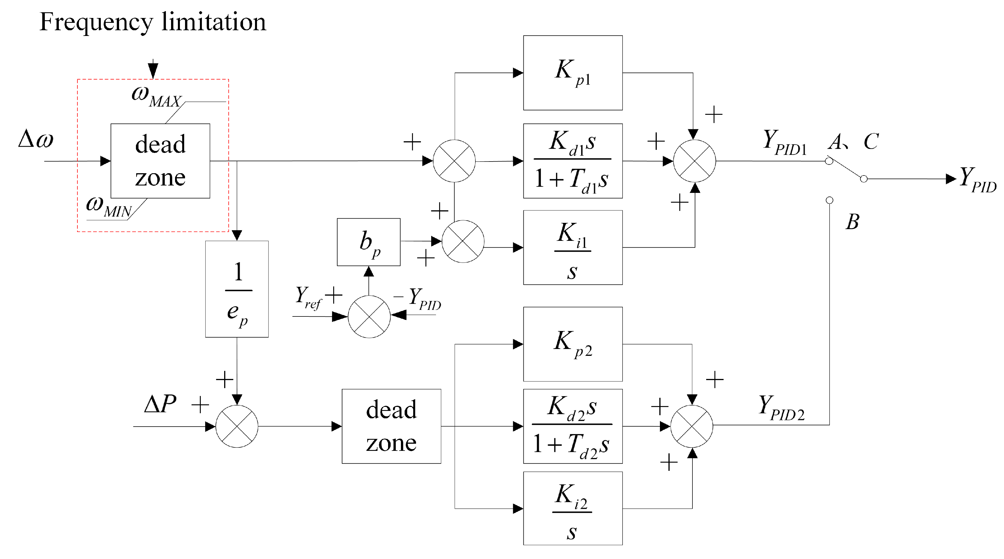
Since the ULFO is mainly manifested as the governor oscillation, when the system frequency returns to the primary frequency regulation dead zone, the governor ceases action. Since the dead zone of the hydraulic turbine governing system is generally 0.05 Hz, that is, for the ULFO, the purpose of damping control index design is to make the frequency oscillation recover to the primary frequency regulation dead zone as soon as possible.
According to the above design principle for hydraulic turbine control system, the turbine guide vane is allowed to trip when it performs three round trips of fully open and fully close. Generally, the governor is set with limited amplitude of generally 10%~20%. Taking the limiting amplitude of 20% as an example, it is assumed that the limiting amplitude is triggered every time of oscillation. Five actions of the guide vane of the hydraulic turbine is equivalent to one full opening and closing, which can withstand 3 × 5 = 15 oscillations. After the number of oscillations is determined, the damping ratio required for the oscillation with different amplitudes to attenuate the primary frequency modulation dead zone can be determined
Considering that the amplitude is 0.5 Hz and the attenuation to 10% is 0.05 Hz, which is exactly within the dead zone of primary frequency modulation, the corresponding damping ratio is at least 2.4%. When the amplitude of ULFO is greater than 0.5 Hz, the attenuation to 10% still can not recover to within 0.05 Hz of primary frequency dead zone. According to formula (5), the required damping is shown in
Table 2 when it is attenuated to within 0.05 Hz of the primary frequency modulation dead zone after 15 oscillations.
When the limiting amplitude of speed governing system is reduced, if the limiting amplitude is 10%, 10 times of turbine guide vane action is equivalent to one full opening and closing, which can withstand 3 × 10 = 30 times of oscillation. According to (3), after 15 oscillations, the required damping is shown in
Table 3.
Under different oscillation frequencies, the corresponding relationship between the governor bearing times of different oscillations and oscillation duration is shown in
Table 4.
It can be seen from the
Table 4 that if the damping control index is set according to 30 times of oscillation, for ULFO with oscillation frequency lower than 0.05 Hz, the duration of oscillation exceeds 10 min. This is unacceptable for dispatching operation.
Therefore, combined with the requirements of the hydraulic turbine governing system’s own bearing capacity and the oscillation times under different limiting conditions, it is suggested that the damping control index of ULFO should be 1.5~2.5% after large disturbance. Considering that the increasement of damping control index expands the range of governor parameter optimization and further weaken the frequency modulation ability, the index should not be further improved.
It should be noted that this index takes no considering of DC modulation. If the effect of DC modulation on ULFO is further considered, the ULFO can be better suppressed.
4. Verification of Proposed Damping Control Index
4.1. Case of ULFO in Real Power System
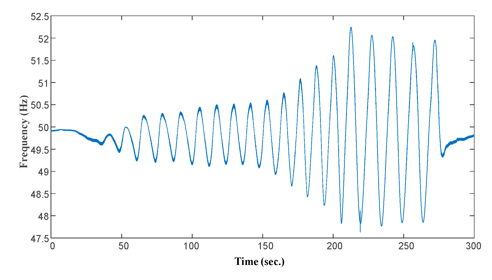
Taking the “01.23” disturbance accident of Central Tibet Power Grid (CTPG) in 2015 as an example. The frequency of CTPG continued to decline from 14:32:20 on that day. The system frequency satys lower than 49.7 Hz for 14 s. At 14:32:34, the frequency, voltage and unit output of CTPG began to fluctuate, and the amplitude gradually increased. The highest frequency of the system is 52.24 Hz, and the lowest frequency is 47.63 Hz. In the process of oscillation, 94,000 kW of load was shed off due to the action of load shedding device at low frequency. At 14:36:34, the governor low oil pressure protection of #1 and #2 units of Zangmu power plant tripped.
According to the design principle of hydraulic turbine control system, in consideration of bearing three times of full opening and closing, the action time limit of governor in CTPG is 20%, and five times of action is equivalent to one full opening and closing. The governor of Zangmu power plant should at least be able to withstand 3 × 5 = 15 times of oscillation, and one more time may lead to low oil pressure protection action. It can be seen from
Figure 7 that when the ULFO occurs, the low oil pressure protection acts and the unit trip after the unit frequency oscillation of 19 times in Zangmu power plant. It shows that the design and operation of the governor meet the requirements, and the low oil pressure protection action after bearing more than 15 times of oscillation is basically consistent with the analysis.
In fact, in order to ensure the adaptability of the index and the safety of power system, this paper adjusts the index to consider more severe conditions, that is, each oscillation triggers the governor-limiting link. Therefore, when the oscillation occurs in a practical system, with the attenuation of the oscillation, the governor limit is triggered by every oscillation. According to the index design criteria proposed in this paper, the governor can actually withstand more oscillation times, which enhances the adaptability of the index to different grid operation modes in the future.
4.2. Simulation Verification in SCPG
SCPG is one of the most complicated ac/dc hybrid reginal grid in China, which, connecting with Central China Power Grid (CCPG), East China Power Grid (ECPG) and North China Power Grid (NCPG) asynchronously through HVDCs, UHVDCs and VSC back-to-backs [
27]. In SCPG, the installed capacity of sustainability energy is more than 75%, including 69.4% hydro, 3.8% wind and 2.2% solar [
14]. In order to maximize the accommodation of sustainability energy, the output power of hydro is more than 85% of total power supply in the season of high water level. In other words, SCPG is a typical hydro-dominant power system. In this paper, SCPG is taken as a typical representative of hydro-dominant power system to illustrate the effectiveness of the proposed index.
According to the above analysis of key factors of ULFO, the smaller the inertia time constant of the unit is, the greater the amplitude of ULFO becomes after fault. Therefore, the risk of ULFO is the most prominent in rain season, when the load is minimum and generation is maximum. Taking SCPG as an example, the maximum amplitude of ULFO after various faults is less than 0.5 Hz. According to the damping control index proposed in this paper, limiting the amplitude to less than 10%, i.e., less than 0.05 Hz, can ensure the frequency to revover to the primary frequency modulation dead zone.
In order to suppress the risk of ULFO after the asynchronous interconnection, the parameters of the speed governing system of large and medium-sized hydropower units in the grid are optimized. The optimization objective is 1.5%, referring to the damping control index of the low-frequency oscillation. After repeated simulation and verification, the parameters of governors of 126 large- and medium-sized hydropower units, are optimized [
5]. Further research shows that when the governor parameters of some units in the system are optimized, the starting mode of optimized units and the distribution of rotating reserve capacity have a significant impact on the ULFO damping [
28].
After considering a severe operating condition, the original optimization of 126 units cannot meet the requirements of ULFO damping control index. In other words, a further optimization is neccessary. Taking 2% as the objective of damping index for the further optimization, the number of optimized units is determined to be 138. After optimization, the ULFO can be effectively suppressed. In the period of peak load, the system frequency oscillation caused by Hongban N-2 fault (severe fault) before and after optimization is shown in the
Figure 8. It can be seen that the ULFO is effectively suppressed.
In order to verify the adaptability of the proposed index under the typical operation mode, the simulation based on the typical operation mode data of SCPG in next 2–3 years is performed. Under the condition of adopting the governor parameter optimization scheme proposed in
Section 3.2, typical N-1, N-2 and other faults are perfomred to evaluate the adaptability of the proposed indicators and strategies. The simulation results are shown in
Figure 9 and
Figure 10. The proposed strategy can effectively suppress the ULFO of the system when a large number of hydropower units are in operation during the rain season. The control index is highly adaptabe to the changed and developed power grid structure.
5. Conclusions
In this paper, the influence factors and design principles of ULFO damping control index of power grid with dominant hydropower are studied. The control index is proposed for designing control strategies to damp ULFOs, enhancing the stability of hydro-dominant power systems and increasing the consumption capacity of hydropower sustainablity energy.
(1) Due to the negative damping effect of hydropower units, there is a risk of ULFO in a power grid with dominant hydropower. The inertia time constant of units, frequency input limit of governor and power output limit of water turbine are the key factors to affect the damping and amplitude of ULFO. Parameter optimization of governor is the most feasible and effective method to suppress ULFO;
(2) The design obejective of ULFO damping control index is that the frequency oscillation can be recovered to the dead zone of primary frequency regulation within a certain times of oscillations. If the damping control index of ULFO is too low, the frequent action of governor may exceed the bearing capacity of mechanical structure and lead to cascading contingencies. If the index is too high, the governor parameters shall be further optimized for ULFO suppression. In the case of ULFO, it is necessary to optimize the governor parameters (reduce PID parameters) in a wider range, which weakens the frequency modulation ability of the system;
(3) For different amplitudes of ULFO, the damping control index requirements are different. Considering the bearing capacity of hydraulic turbine governing system and the requirements of oscillation times under different limiting conditions, the damping control index of ULFO in a typical provincial power grid after large disturbance should be set as 1.5–2.5%.

 ,
, 


