Article

Reduction of Inrush Current in a Shockwave Non-Thermal Food Processing System Using an Exponential Clock Pulse Generator

1
Department of Information Electronics, Fukuoka Institute of Technology, Fukuoka 811-0295, Japan
2
Department of Electrical and Electronics Engineering, Maltepe University, 34857 Istanbul, Turkey
3
Department of Information, Communication and Electronic Engineering, National Institute of Technology, Kumamoto College, Kumamoto 861-1102, Japan
*
Author to whom correspondence should be addressed.
Sustainability 2020, 12(15), 6095; https://doi.org/10.3390/su12156095
Submission received: 29 June 2020 / Revised: 22 July 2020 / Accepted: 27 July 2020 / Published: 29 July 2020
(This article belongs to the Section Sustainable Chemical Engineering and Technology)

Abstract

:
Recently, shockwave food processing is drawing much attention as a low-cost non-thermal food process technique. In shockwave non-thermal food processing, underwater shockwaves are generated by a high voltage generator. Therefore, high inrush currents and high voltage stress on circuit components significantly reduce the reliability and life expectancy of the circuit. However, to the best of our knowledge, stress reduction techniques and their experimental verification have not been studied yet in the shockwave non-thermal food processing system. In this paper, we propose a stress reduction technique for the shockwave non-thermal food processing system and investigate the effectiveness of the proposed technique experimentally. To achieve high reliability and life expectancy, a new high voltage multiplier with an exponential clock pulse generator is proposed for the shockwave non-thermal food processing system. By slowing down the rate at which the capacitors charge in the high voltage multiplier, the exponential clock pulse generator significantly reduces the inrush current. Furthermore, to perform shockwave non-thermal food processing continuously at a lower voltage level, we present a new electrode with a reset mechanism for wire electric discharge (WED), where a square-shaped metal wire swings on a hinge in the proposed electrode. The proposed electrode enables not only shockwave generation at a lower voltage level but also continuous non-thermal food processing, because the square-shaped metal wire is not melted in the WED process. To confirm the validity of the proposed techniques, some experiments are performed regarding the laboratory prototype of the shockwave non-thermal food processing system. In the performed experiments, reduction of inrush currents and effective food processing are confirmed.

1. Introduction

The declining birthrate and aging population have become a social problem in many developed countries, such as Japan, Germany, Portugal, and Italy. For a healthy life of elderly persons, it is necessary to develop nutritious and soft processed foods. However, many nutrients are destroyed by heat processing [1,2,3]. For this reason, non-thermal food processing technology [4], which can provide nutritious soft processed foods, is drawing attention. In past studies, some non-thermal food processing techniques have been proposed. For example, Wang et al. introduced the non-thermal food processing using high hydrostatic pressure technology [5,6,7,8]. The high hydrostatic pressure technology has several advantages in that vegetative microorganisms are killed, and foods are not polluted with harmful substances, with or without packaging. However, as reported in [9,10], this technology fails to destroy spores at a pressure of 1200 MPa. Distinguished from the high hydrostatic pressure technology, the non-thermal food processing using high voltage arc discharge technology [11,12,13] has been extensively researched in past studies. In this technology, foods are destroyed by a strong shockwave generated by the arc discharge, where the processed food is crushed without retaining its original shape. The high voltage arc discharge technology can realize non-thermal food processing at high speed. However, this method impairs the flavor of foods and may form chemical substances that are harmful to the human body [14]. For liquid or semi-solid foods, the non-thermal food processing using pulsed electric field technology [15,16] is one of the most effective technologies. By using short electric pulses, the pulsed electric field technology can offer not only microbial inactivation but also the reduction of detrimental changes in food quality and nutrition [17]. However, an apparatus for generating short electric pulses is expensive [18]. Following this study, the non-thermal food processing using cold plasma technology [19] has been proposed to improve food safety, where cold plasma inactivates contaminating microbes on foods. The cold plasma technology can be used for a wide range of foods [20], such as apples, lettuce, eggs, and processed meats and cheeses. However, as with pulsed electric field technology, expensive devices are required to achieve the non-thermal food processing using cold plasma technology [21].
For the above-mentioned reason, to realize the non-thermal food processing at a low cost, the shockwave non-thermal processing and its applications have received much attention in recent years. For example, Shimojima et al. provided rice flour by crushing rice [22,23,24] with an underwater shock wave, and Udagawa et al. proposed a microorganism treatment technology using underwater shockwaves [25]. Furthermore, the mechanism of the shockwave generation by underwater discharge is investigated by Higa et al. [26], and the characteristics of the shockwave propagation are clarified through computer simulations [27,28]. The shockwave non-thermal food processing system mainly consists of a high voltage generator, a high voltage switch, metal electrodes, and a pressure vessel. In the shockwave non-thermal processing, first, the high voltage multiplier generates a high voltage [29], where the high voltage is stored in a large capacitor. Next, through high voltage switches, the electrical energy stored in the capacitor is discharged in a water-filled pressure vessel. In this timing, the electrical energy turns into shockwaves. Finally, the shockwave destroys only the internal tissue of a target food. Therefore, improvements in high voltage multipliers, pressure vessels, voltage switches, and metal electrodes are required to achieve effective shockwave non-thermal processing. In past studies, several attempts have been made to improve the components of the shockwave non-thermal food processing system. For example, regarding the design of the pressure vessel, Miyafuji et al. designed the pressure vessel for manufacturing rice powder in [30,31,32,33]. Concerning the design of the metal electrode, Higa et al. performed shockwave non-thermal food processing using a wire electric discharge (WED) [34,35,36,37]. Furthermore, several types of high voltage multipliers have been proposed in the field of electrical engineering. Among others, the Cockcroft–Walton voltage multiplier (CWVM) [38] is one of the most promising multipliers for shockwave non-thermal food processing systems, because a high turns ratio transformer is not required. The transformer-less structure of the CWVM can provide low cost and light weight. For this reason, many types of CWVMs and their families have been developed in past studies. For example, Wang et al. proposed a cascade CWVM with a symmetrical structure [39]. Young et al. suggested a transformer-less voltage multiplier by combining a boost converter with a CWVM [40]. Unlike these CWVMs, Iqbal et al. developed a bipolar CWVM [41,42] by combining a positive CWVM and a negative CWVM. Furthermore, Iqbal designed a hybrid CWVM with a symmetrical bipolar topology [43]. However, the response speed of these bipolar CWVMs is slow, because diode switches are driven by a commercial power source. To solve this problem, Abe et al. suggested a high-speed CWVM [44,45] by using a full waveform rectifier and high/low side drivers. However, these CWVMs have difficulty achieving high voltage gain. To realize a high voltage gain, Gosset et al. proposed a cascade-connected voltage doubler [46], and Ding et al. developed a series-connected voltage multiplier by combining two types of inductor-less converters [47,48]. Although these topologies have improved the voltage gain, the response speed is still slow. To realize fast response as well as high voltage gain, Jaiwanglok et al. designed a switched capacitor-based voltage multiplier by combining two bipolar voltage multipliers via a level shift driver [49,50]. However, a switched capacitor-based voltage multiplier suffers from high inrush currents and high voltage stress on circuit components, though it enables fast response and high voltage gain. These stresses significantly reduce the reliability and life expectancy of the circuit. However, to the best of our knowledge, stress reduction techniques and their experimental verification have not been studied yet in the non-thermal food processing system utilizing underwater shockwaves.
To improve the reliability and life expectancy, we propose a stress reduction technique for the shockwave non-thermal food processing system and investigate the effectiveness of the proposed technique experimentally in this paper. The key idea of the proposed technique is the restraint of the speed in capacitor charging at start-up. In the proposed voltage multiplier for generating a high voltage such as 3.5 kV, transistor switches are controlled by the proposed exponential clock pulse generator. In addition, low voltage stress on circuit components is achieved by the modified bipolar topology of the Cockcroft–Walton voltage multiplier. The novel point of the proposed technique is that the inrush current of the proposed voltage multiplier is suppressed by increasing the charging speed of capacitors exponentially. This technique will enable the reduction of stress on the circuit components of shockwave non-thermal food processing systems. Furthermore, a wire electric discharge (WED) using an electrode with a reset mechanism is employed to generate shockwaves at a lower voltage level. In the proposed electrode with a reset mechanism, a square-shaped metal wire swings on a hinge. Therefore, the proposed electrode enables not only shockwave generation at a lower voltage level but also continuous non-thermal food processing, because the square-shaped metal wire is not melted in the WED process. The combination of these two techniques, viz., an exponential clock pulse generator and an electrode with a reset mechanism, will improve the reliability and life expectancy of shockwave non-thermal food processing systems. To confirm the effectiveness of the proposed technique, some experiments were performed concerning the laboratory prototype of the non-thermal food processing system utilizing underwater shockwaves.
The rest of this paper is organized as follows. First, the configuration of the proposed non-thermal food processing system is described in Section 2, where the details of the high voltage multiplier, the exponential clock pulse generator, and the electrode are explained. Next, to clarify the effectiveness of the proposed technique, some experiments are conducted in Section 3, where the shockwave non-thermal food processing is performed concerning a laboratory prototype. Finally, the results of this work are briefly summarized in Section 4.

2. Non-Thermal Food Processing System Utilizing Underwater Shockwaves

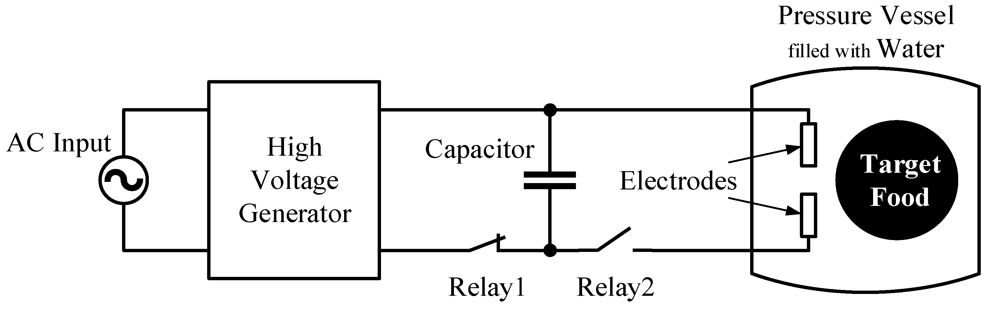
2.1. System Configuration

The system configuration of the shockwave non-thermal food processing system is illustrated in Figure 1. As it can be seen from Figure 1, the shockwave non-thermal food processing system mainly consists of a high voltage generator, a high voltage relay, metal electrodes, and a pressure vessel. Unlike existing non-thermal food processing systems, the shockwave non-thermal food processing system does not require expensive devices. Furthermore, these components can be designed on a large scale. For this reason, it is not difficult to design the proposed apparatus on a large scale.
The operation principle of the shockwave non-thermal food processing system is as follows: First, a high voltage, such as 3.5 kV, is generated by the high voltage generator by converting a 100 V ac input at 60 Hz. Next, the output voltage of the high voltage generator is stored in a large capacitor. Then, the electric charge stored in the large capacitor is discharged using the high voltage relay, where large current flows between the electrodes. After that, the large current causes underwater shockwaves. Finally, the shockwave destroys only the internal tissue of the target food without heating. As it can be seen from Figure 1, the key components for achieving efficient food processing are the pressure vessel, the high voltage generator, and the electrodes.
In the following subsections, a new high voltage multiplier and its control circuit are presented to reduce the stress on circuit components in the shockwave non-thermal food processing system.

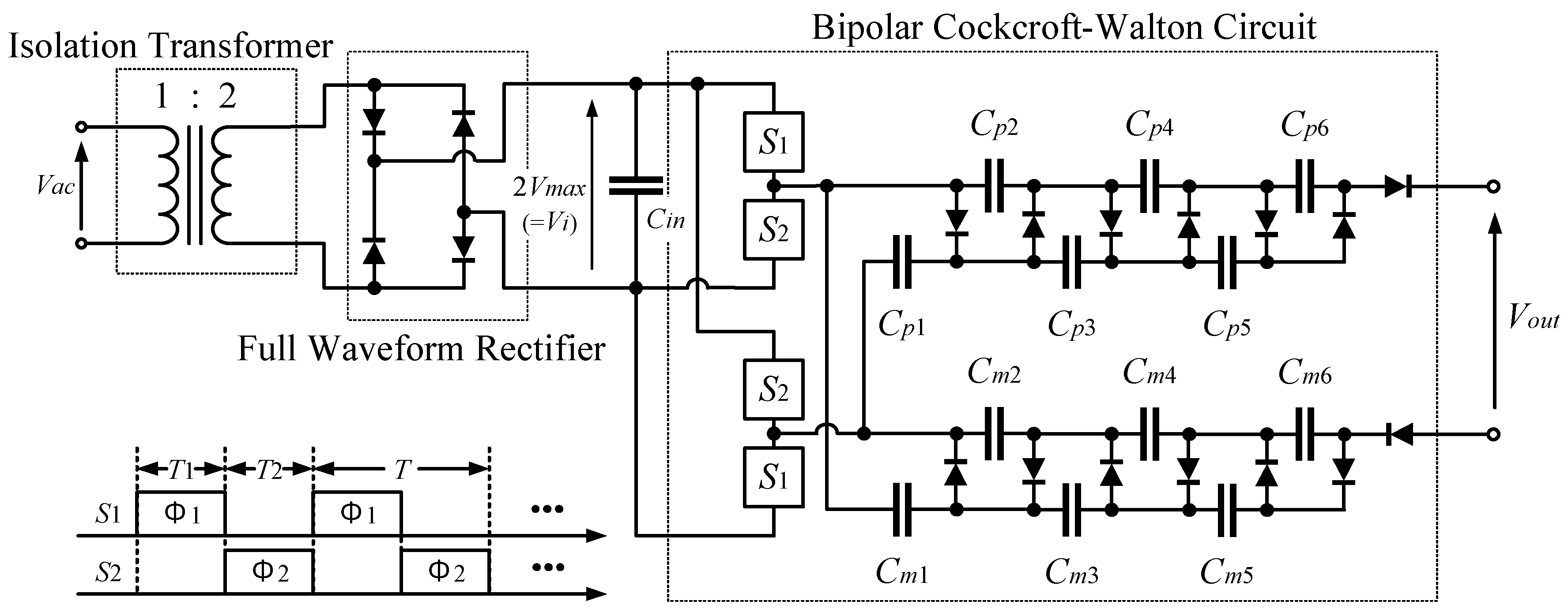
2.2. High Voltage Generator

Figure 2 illustrates the circuit configuration of the proposed voltage multiplier. The output voltage and energy stored in the output capacitor depend on the target food. In past studies, rice powder was produced using 4.9 kJ at a voltage of 3.7 kV and apple juice was made using 1.23 kJ at a voltage of 3.5 kV. Based on these previous studies, we designed the high voltage multiplier with an output voltage 3.5 kV, where the output capacitor was set to 200 μF. As it can be seen from Figure 2, the proposed voltage multiplier consists of three blocks: the isolation transformer, the full waveform rectifier, and the bipolar Cockcroft–Walton circuit. First, the ac input Vac (= 100 V at 60 Hz) is doubled by the isolation transformer. Next, the output of the isolation transformer is converted to the dc voltage 2 Vmax (= Vi) by the full waveform rectifier, where Vmax denotes the amplitude of Vac. Then, high-speed rectangular pulses with the amplitude 2Vmax (= Vi) are generated by controlling the power switches S1 and S2, where S1 and S2 are driven by an exponential clock pulse generator. After that, the high-speed rectangular pulses are converted by the bipolar Cockcroft–Walton circuit. Finally, the output capacitor is charged by the voltage Vout. Therefore, the stress on S1 and S2 is 2 Vmax and the stress on the capacitors is 4 Vmax.
In the following, we analyze the characteristics of the proposed voltage multiplier theoretically. In the theoretical analysis, the physical model of the proposed voltage multiplier is derived by utilizing the four-terminal equivalent model shown in Figure 3. In this figure, the four-terminal equivalent model consists of an ideal transformer and a linear resistor, where m is the conversion ratio of the ideal transformer and RSC is the internal resistance of the circuit. The theoretical analysis is performed under the following assumptions: (i) on-resistances of all transistor switches Sj (j = 1, 2) is Ron, (ii) on-resistances of all diode switches is Rd, and (iii) the time constant is much bigger than the period of clock pulses, T.
In a steady state condition, the instantaneous equivalent circuits of the bipolar Cockcroft–Walton circuit shown in Figure 2 are expressed by Figure 4, where the threshold voltage of diode switches is neglected. In this figure, Vmax is the amplitude of Vin, Ron is the on-resistance of Sj, Rd is the on-resistance of the diode switches, Δ q T j , v i is the variation of the electric charge in the input terminal, and Δ q T j , v o u t (= Δ q T j , v o p = − Δ q T j , v o m ) is the variation of electric charge in the output terminal. Since the sum of the variations in the electric charge of capacitors, Δ q T j p k and Δ q T j m k (For (j = 1, 2) and (k = 1, …, 6)), is zero in the cycle, the variation of the electric charge, Δ q T j p k and Δ q T j m k , satisfies
Δ q T 1 p k + Δ q T 2 p k = 0
and
Δ q T 1 m k + Δ q T 2 m k = 0
where
T = T 1 + T 2   and   T 1 = T 2 = T / 2
Applying Kirchhoff’s current law for Figure 4, the relationship between Δ q T j , v i , Δ q T j , v o p , and Δ q T j , v o m is expressed as follows:
State-T1:
Δ q T 1 , v i = Δ q T 1 p 1 Δ q T 1 p 2 Δ q T 1 p 3 + Δ q T 1 m 1
Δ q T 1 , v o p = Δ q T 1 p 6
and
Δ q T 1 , v o m = Δ q T 1 m 6
State-T2:
Δ q T 2 , v i = Δ q T 2 p 1 + Δ q T 2 m 2
Δ q T 2 , v o p = 0
and
Δ q T 2 , v o m = 0
It is noteworthy that the bipolar Cockcroft–Walton circuit has a symmetric relationship between Figure 4a,b. Hence, Δ q T j p k and Δ q T j m k satisfies the following condition:
Δ q T j p k = Δ q T j m k
Furthermore, from Equations (1)–(9), we have
Δ q T 1 p 1 = Δ q T 1 m 1 = 3 Δ q T 1 p 6
Δ q T 1 p 2 = Δ q T 1 m 2 = 3 Δ q T 1 p 6
Δ q T 1 p 3 = Δ q T 1 m 3 = 2 Δ q T 1 p 6
Δ q T 1 p 4 = Δ q T 1 m 4 = 2 Δ q T 1 p 6
Δ q T 1 p 5 = Δ q T 1 m 5 = Δ q T 1 p 6
Δ q T 1 , v i = 7 Δ q T 1 p 6
and
Δ q T 2 , v i = 6 Δ q T 1 p 6
Since the input current and output currents, Ii, Iop (= Iout) and Iom (= −Iout), can be obtained by diving the sum of the variation of the electric charges by T, the relationship between these currents are expressed as
I i = Δ q v i T = Δ q T 1 , v i + Δ q T 2 , v i T
I o p = Δ q v o p T = Δ q T 1 , v o p + Δ q T 2 , v o p T
and
I o m = Δ q v o m T = Δ q T 1 , v o m + Δ q T 2 , v o m T
Insert Equations (1)–(17) into Equations (18)–(20), we have the relationship between Ii and Iout as
I i = 13 I o u t   and   Δ q v i = 13 Δ q v o u t
where I o u t = I o p = I o m and Δ q v o u t = Δ q v o p = Δ q v o m . From Equation (21), we get the parameter m = 13.
Next, we ague the consumed energy of Figure 4 to derive the parameter RSC. In Figure 4, the total consumed energy WT can be expressed as
W T = W T 1 + W T 2
where W T j is the consumed energy of the circuit shown in Figure 4 in State-Tj. From Figure 4a,b, W T j is calculated as
W T 1 = R d T 1 ( Δ q T 1 p 3 Δ q T 1 p 1 ) 2 + R d T 1 ( Δ q T 1 p 5 Δ q T 1 p 3 ) 2 + R d T 1 ( Δ q T 1 p 5 ) 2 + R d T 1 ( Δ q T 1 p 6 ) 2 + R d T 1 ( Δ q T 1 m 1 Δ q T 1 m 3 ) 2 + R d T 1 ( Δ q T 1 m 3 Δ q T 1 m 5 ) 2 + R d T 1 ( Δ q T 1 m 5 ) 2 + R d T 1 ( Δ q T 1 m 6 ) 2 + 2 R o n T 1 ( Δ q T 1 , v i ) 2
and
W T 2 = R d T 2 ( Δ q T 2 p 3 Δ q T 2 p 1 ) 2 + R d T 2 ( Δ q T 2 p 5 Δ q T 2 p 3 ) 2 + R d T 2 ( Δ q T 2 p 5 ) 2 + R d T 2 ( Δ q T 2 m 1 Δ q T 2 m 3 ) 2 + R d T 2 ( Δ q T 2 m 3 Δ q T 2 m 5 ) 2 + R d T 2 ( Δ q T 2 m 5 ) 2 + 2 R o n T 2 ( Δ q T 2 , v i ) 2 .
Substituting Equations (11)–(17) into Equations (22)–(24), the total consumed energy is rewritten as
W T = ( 28 R d + 340 R o n ) ( Δ q V o u t ) 2 T
On the other hand, the four-terminal equivalent model shown in Figure 3 has the following total consumed energy:
W T = R S C ( Δ q V o u t ) 2 T
Therefore, from Equations (25) and (26), we can easily determine RSC as 28   R d + 340   R o n . By combing m = 13 and RSC = 28 R d + 340 R o n , the equivalent model of the bipolar Cockcroft–Walton circuit can be obtained as
[ V i I i ] = [ 1 / 13 0 0 13 ] [ 1 28 R d + 340 R o n 0 1 ] [ V o u t I o u t ]
because the equivalent circuit can be expressed by Figure 3. Hence, the equivalent circuit of the proposed voltage multiplier shown in Figure 2 can be expressed by
[ V m a x I i n ] = [ 1 / 26 0 0 26 ] [ 1 28 R d + 340 R o n 0 1 ] [ V o u t I o u t ]
As it can be seen from Equation (28), the parameter RSC has a strong influence on the power loss of the proposed voltage multiplier. That is to say, RSC is one of the most important factors in designing an efficient high voltage multiplier. If Rd and Ron are negligibly small, we have the ideal output voltage 26 × 100 2 V ( 3.67 kV) by the proposed voltage multiplier.
Table 1 summarizes the comparison between the proposed voltage multiplier and conventional voltage multipliers, where N (= 1,2, …) is the number of stages of the voltage multiplier and M (= 1, 2, …) is the number of converter blocks. In Table 1, we omit the Cockcroft–Walton voltage multiplier utilizing inductors, because it has high voltage stress on circuit components. As it can be seen from Table 1, the conventional voltage multiplier reported in [46] has the highest voltage stress on circuit components, although it can achieve the highest voltage gain. Therefore, a special capacitor with high breakdown voltage is necessary to design the conventional voltage multiplier reported in [46]. On the other hand, the conventional voltage multipliers reported in [38,41,43,46,47,48] are driven directly by an ac input, resulting in a slow response. Needless to say, the speed of the voltage multiplier has a strong relationship with the processing speed of the shockwave non-thermal food processing system. Therefore, a high-speed voltage multiplier is desirable to offer high speed food processing. As it can be seen from Table 1, in a balance of voltage gain, response speed, and stress on circuit components, the proposed voltage multiplier is suitable for the shockwave non-thermal food processing system.
In the following subsection, the control method to reduce inrush currents of the high voltage multiplier is discussed.

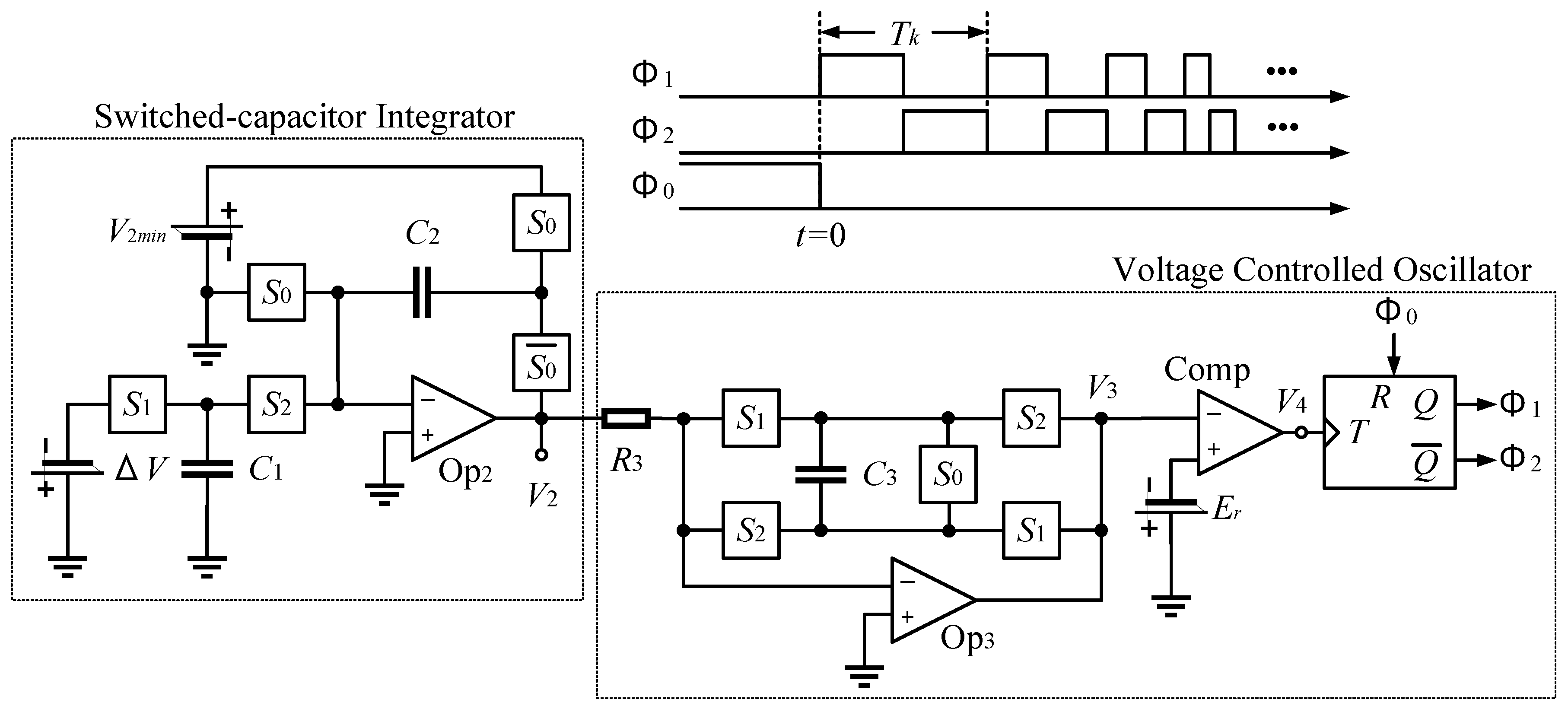
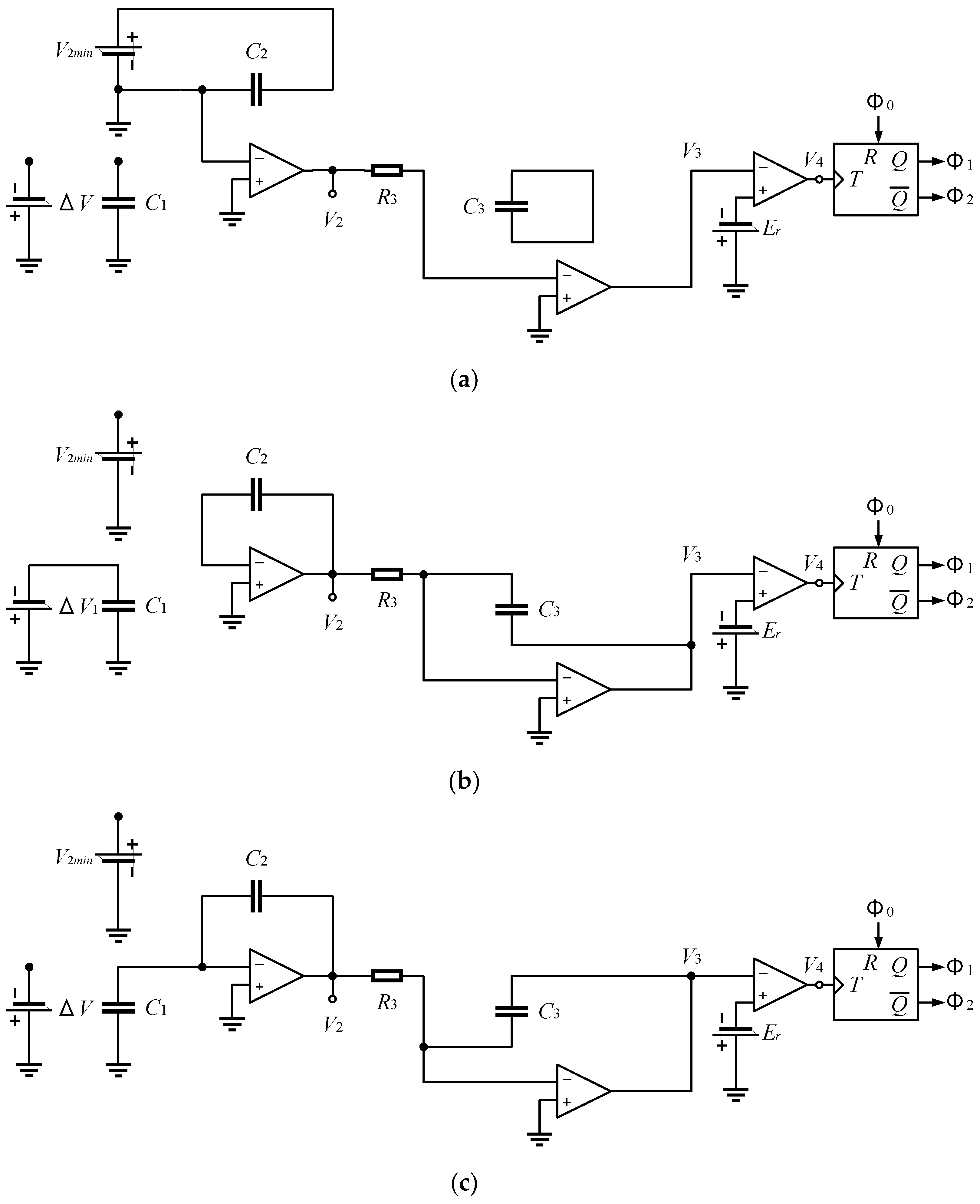
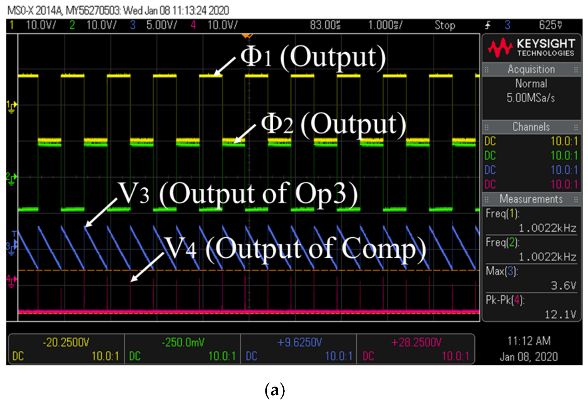
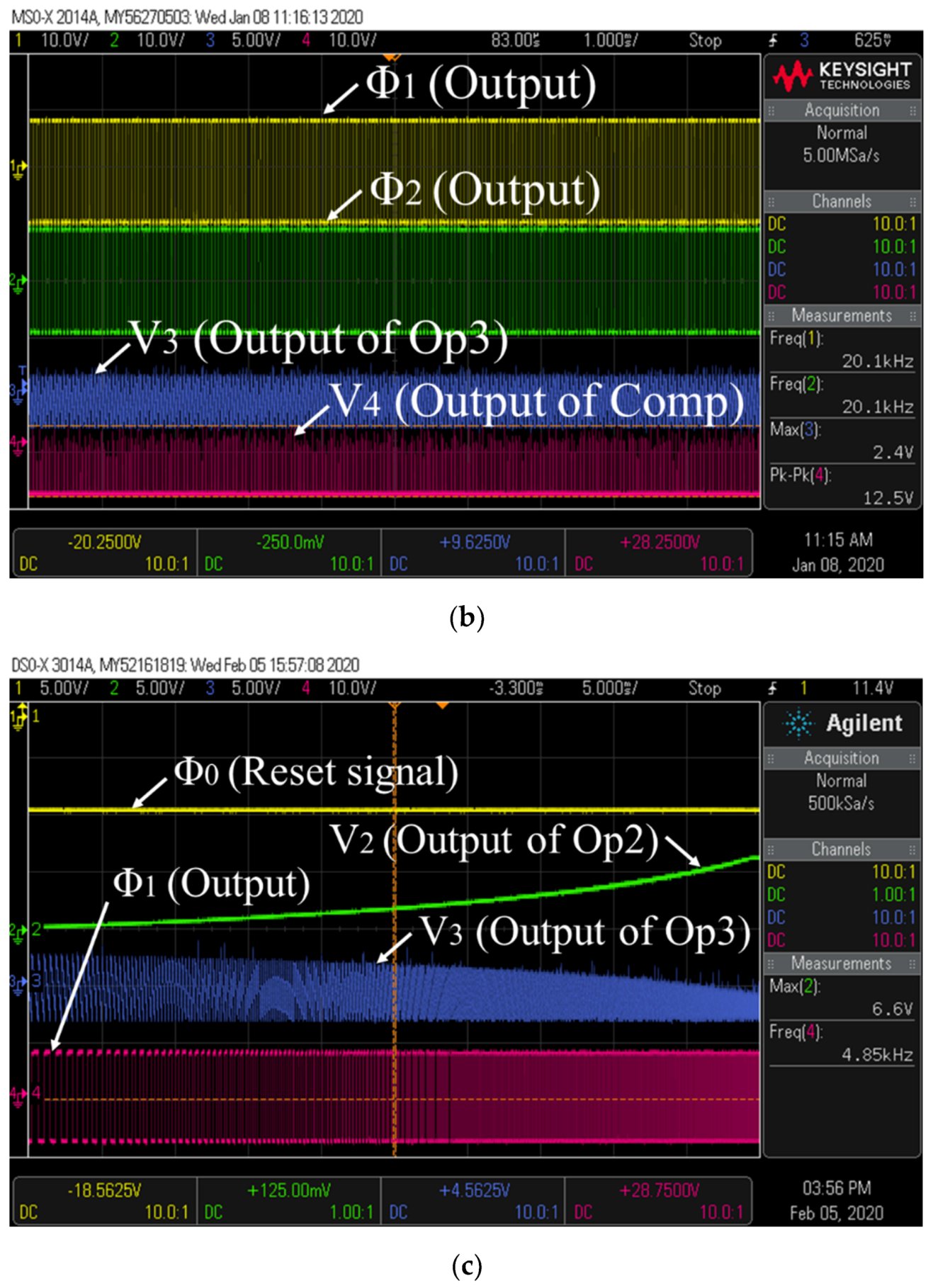
2.3. Clock Pulse Generator

Due to high current stress on circuit components, high inrush currents significantly reduce the reliability and life expectancy of circuits. Therefore, to reduce inrush currents of the high voltage generator, we employ the exponential clock pulse generator reported in our previous work [51], where the transistor switches S1 and S2 shown in Figure 2 are driven by the exponential clock pulse generator. By slowing down the rate at which the capacitors charge in the high voltage multiplier, the exponential clock pulse generator reduces the inrush current.
Figure 5 illustrates the circuit configuration of the exponential clock pulse generator reported in [51]. The clock pulse generator shown in Figure 5 can be divided into two blocks: the switched-capacitor (SC) integrator and the voltage-controlled oscillator (VCO). By switching transistor switches S0, S1, and S2, the instantaneous equivalent circuits of the exponential clock pulse generator are expressed as Figure 6. The operation principle of the clock pulse generator is as follows: In an initial condition, the initial voltage of C2 becomes V2min when Φ0 is “High”. Next, the capacitor C2 is charged up to −ΔV when S1 is turned on. Then, the electric charge of C1 is transferred to C2 when S2 is turned on. By repeating these processes, the voltage V2 becomes
V 2 ( t = n T ) = V 2 m i n + n C 1 C 2 Δ V
at the n-th cycle. Furthermore, the clock frequency of VCO becomes
f n = 1 T n = 1 4 C 3 R 3 E r V 2 ( t = n T )
at the n-th cycle. From (29) and (30), the time t is obtained as
t = k = 0 n T k   4 C 2 C 3 R 3 E r C 1 Δ V l n { 1 V 2 m i n V 2 ( t ) }
if n is large enough. Therefore, from Equations (30) and (31), the clock frequency f is derived as
f = 1 4 C 3 R 3 E r V 2 m i n ε C 1 Δ V 4 C 2 C 3 R 3 E r t = ( 1 4 C 3 R 3 E r ) ε t τ
where
τ = 4 C 2 C 3 R 3 E r C 1 Δ V
As it can be seen from Equations (32) and (33), the frequency of the clock pulses Φ1 and Φ2 speeds up exponentially. In the proposed voltage multiplier shown in Figure 2, the switches S1 and S2 are driven by Φ1 and Φ2. Therefore, the inrush currents of the high voltage multiplier are reduced by the exponential clock pulse generator shown in Figure 5.

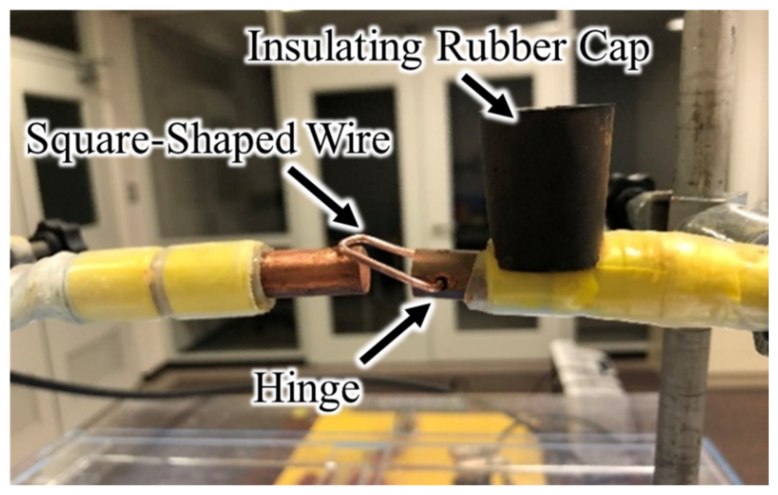
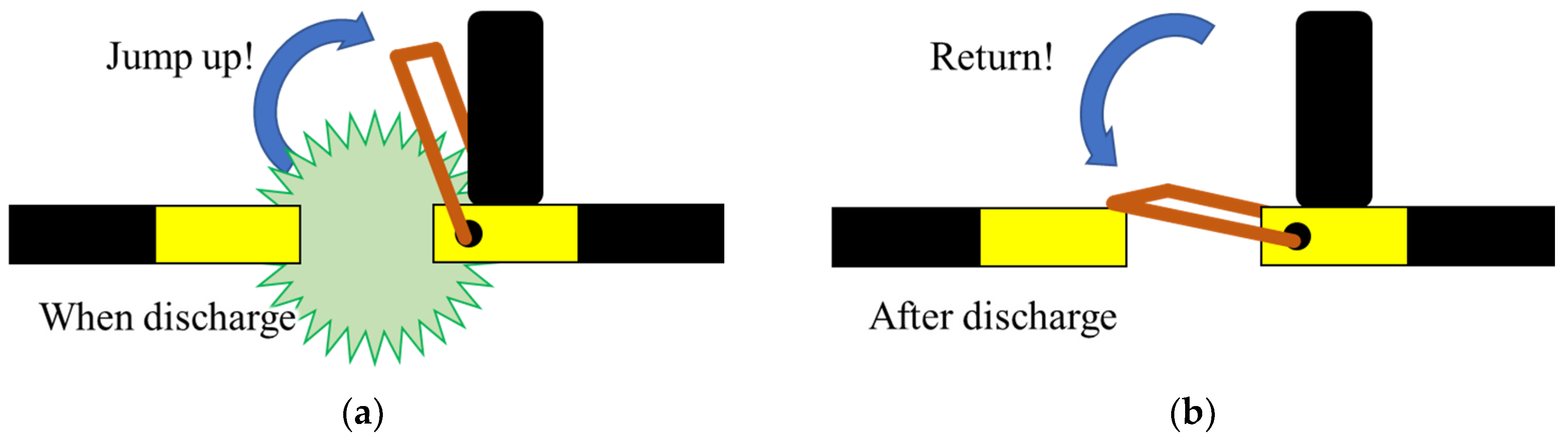
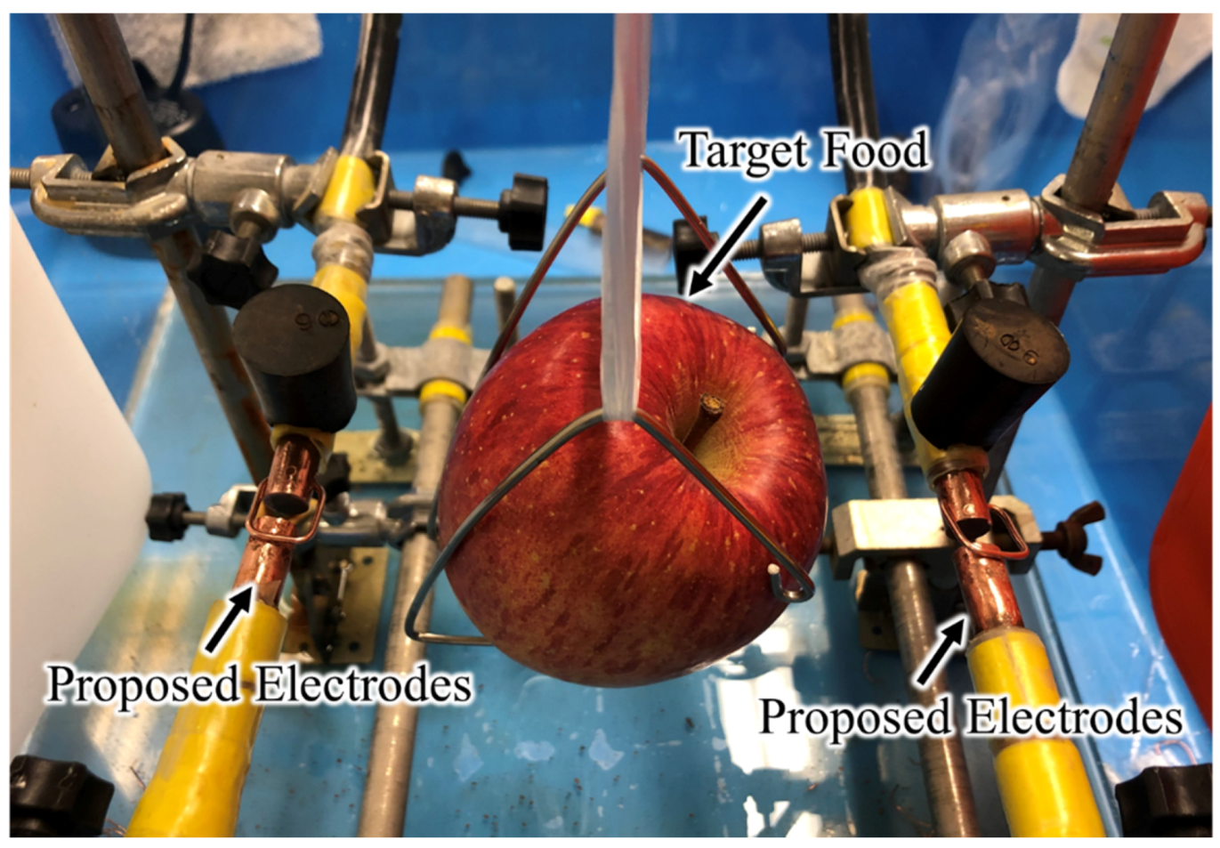
2.4. Electrodes for Pulsed Wire Discharge

By utilizing the WED technique [34,35,36,37,38,39,40,41,42,43,44,45,46,47,50], shockwaves can be generated at a lower voltage level. However, thin metal wires between electrodes are melted by the WED process. Hence, by the replacement of the thin metal wire, it is impossible to continuously perform shockwave non-thermal food processing. To overcome this problem, we propose a new electrode with a reset mechanism. Of course, the discharging characteristic depends on diameter of electrodes, materials, spark gap, etc. However, the discussion on these factors is omitted to argue the design of electrodes in this paper.
Figure 7 depicts the proposed electrode. As it can be seen from Figure 7, a square-shaped copper wire is connected to the copper electrode, where the 25 × 15 mm square-shaped wire swings on a hinge. Since the electrodes with the square-shaped metal wire reduces the resistance between the electrodes, large current flows between the electrodes instantaneously. Figure 8 illustrates the operation principle of the proposed electrode in a discharging process. First, large current flows between electrodes through the square-shaped metal wire. By the large current, air bubbles are generated with the shockwaves. Next, as shown in Figure 8a, the square-shaped wire jumps up due to the air bubbles caused by underwater explosion. Then, the square-shaped wire bounces off the insulating rubber cap connected to the electrode, because it has a hinge mechanism. Finally, as shown in Figure 8b, the square-shaped wire returns to its original position. Since the square-shaped metal wire is not melted by the WED process, the shockwave non-thermal food processing can be performed continuously. Of course, the copper oxidation of electrodes affects the discharging characteristics. However, the reduction in energy stored in the output capacitor is only 2.3% if the oxidation of copper creates an oxide barrier that requires 40 V conduction. The detailed analysis about the effects of electrode impurities will be conducted in a future study.

3. Experimental Study

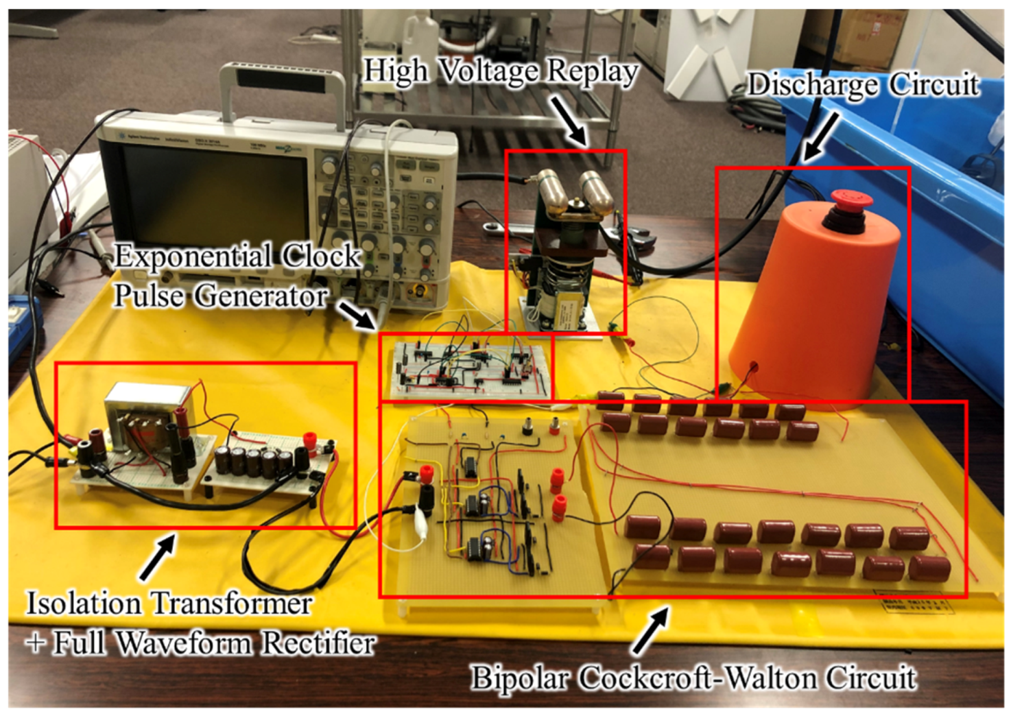
3.1. Experimental Setup of the Non-Thermal Food Processing System

To confirm the validity of the proposed non-thermal food processing system, some experiments were performed concerning the laboratory prototype shown in Figure 9. As this figure shows, the experimental system consists of a high voltage multiplier, a high voltage relay, an exponential clock pulse generator, and a discharging circuit, where the high voltage multiplier was built with the circuit components shown in Table 2. In the voltage multiplier, a high voltage, such as more than 3.5 kV, was generated by converting the ac input voltage 100 V at 60 Hz, where the diode 1N4007 was used to reduce the fabrication cost of the proposed system. The output voltage of the voltage multiplier was provided to an output capacitor produced by TOEI corporation, where the capacitance was 200 μF and the rated voltage was 4000 V DC. The terminals of the output capacitor were connected to the proposed electrodes with a reset mechanism in the chamber as shown in Figure 10, and the chamber was filled with tap water. Since the proposed system does not require the maintenance of water insulation, the non-thermal food processing can be achieved at low cost. As it can be seen from Figure 10, two pairs of electrodes were connected to the output capacitor in order to process both sides of the target food by only one electric discharge, where the gap between electrodes was set to 10 mm. In this experiment, in order to investigate the effect of underwater shockwaves, an apple was used as the target food, because the effect of underwater shockwaves can be confirmed by the discoloration of the apple flesh. The output capacitor was discharged by the high voltage relay EA12-NC-20-1-100-BD, which is produced by Ross Engineering, as shown in Figure 9, where the HV contacts were 12 kV and the insulation to ground was 20 kV.

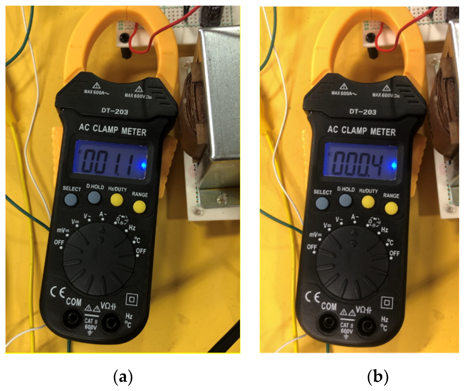
3.2. Reduction of Inrush Currents by the Exponential Clock Pulse Generator

In this subsection, the validity of the exponential clock pulse generator is confirmed experimentally. Figure 11 demonstrates the measured clock pulses obtained by the exponential clock pulse generator, where the exponential clock pulse generator was built with the circuit components shown in Table 3. In the performed experiment, the circuit parameters were set as shown in Table 4. In the parameter setting shown in Table 4, the voltage V2 increases from 0.4 V (= V2min) to 7.9 V (= V2max), where the frequency varies from 1 kHz (= fmin) to 20 kHz (= fmax). As it can be seen from Figure 11, the exponential clock pulse generator can generate the exponential clock pulse from 1 kHz to 20 kHz.
To confirm the validity of the exponential clock pulse generator, the proposed voltage multiplier shown in Figure 2 was driven by the exponential clock pulse generator shown in Figure 5. Figure 12 demonstrates the measured inrush currents of the voltage multiplier. As it can be seen from Figure 12, the exponential clock pulse generator can reduce the inrush current from 1.1 A to 0.4 A. In other words, the proposed exponential clock pulse can reduce about 63.6% inrush current from the traditional fixed clock pulse.

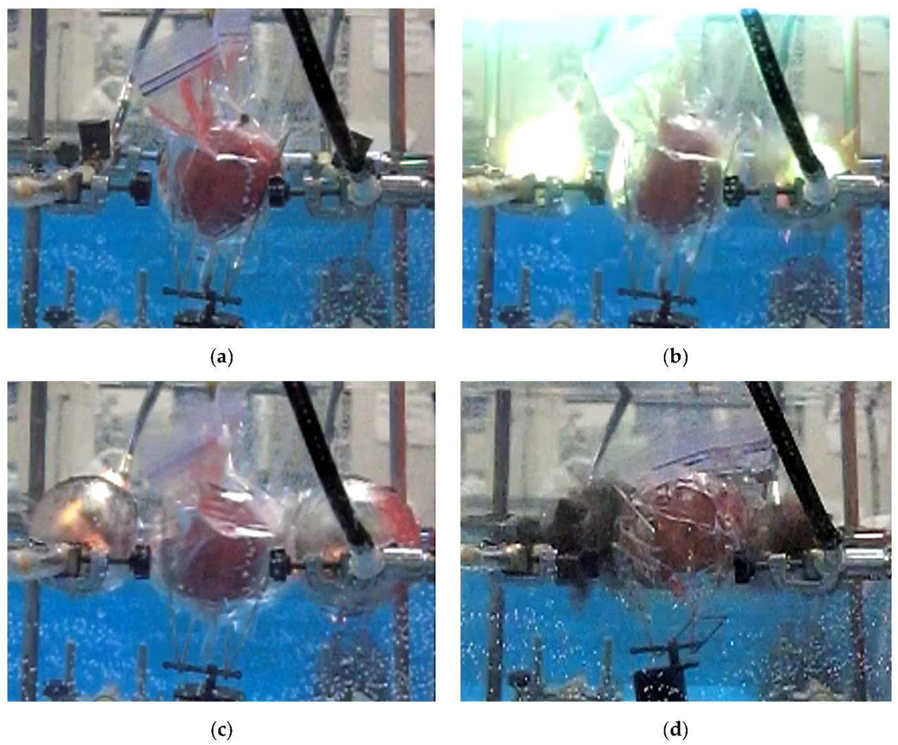
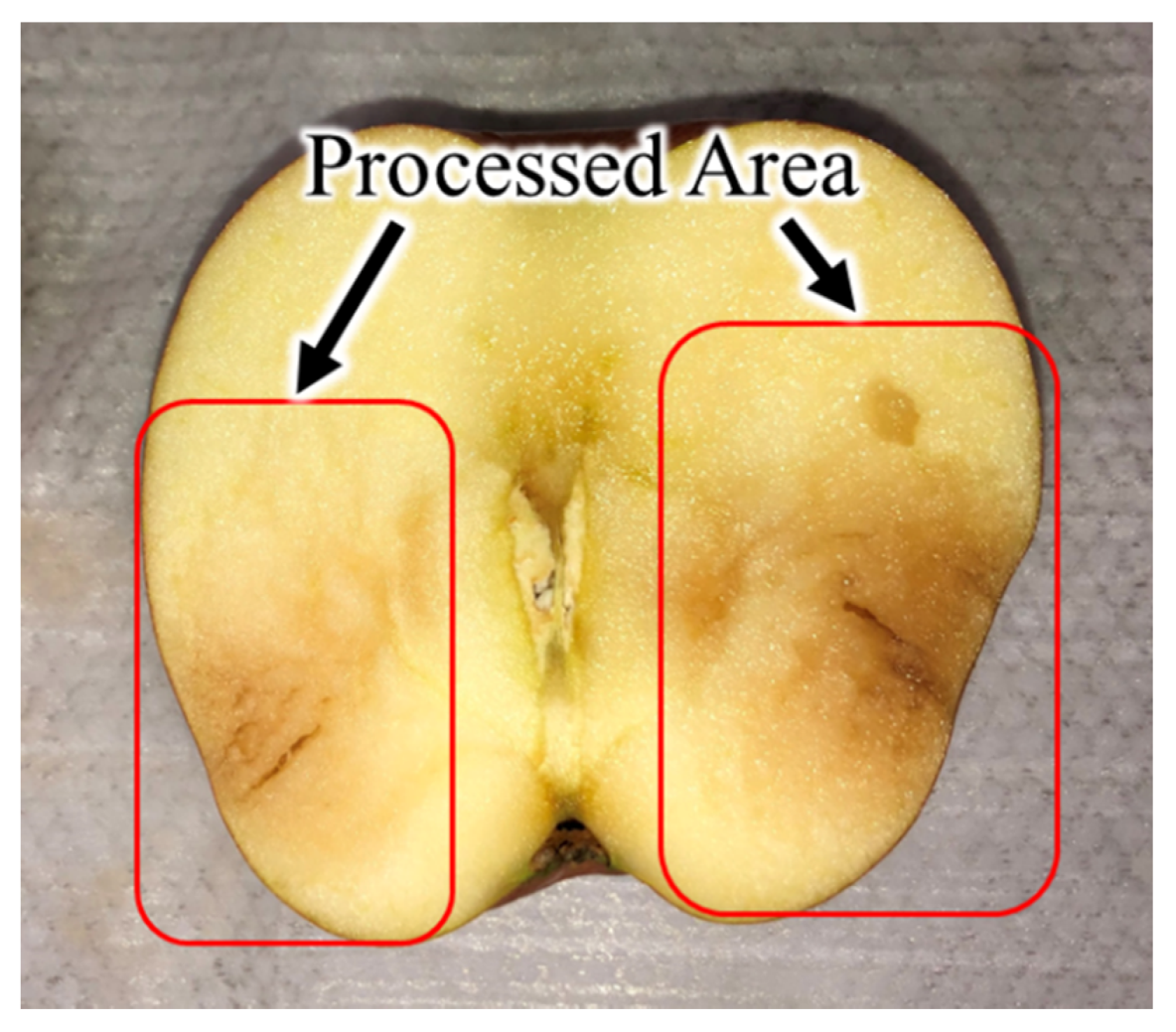
3.3. Non-Thermal Food Processing Utilizing Underwater Shockwaves

In this subsection, the effectiveness of the proposed non-thermal food processing system is clarified by some laboratory experiments. Figure 13 demonstrates the non-thermal food processing captured by the high-speed camera EX-100PRO. As it can be seen from Figure 13, the electric discharge occurred from both electrodes at the same time. Figure 13a is the initial state, Figure 13b is the light emitting state during electric discharge, Figure 13c is the state of electric bubble formation, and Figure 13d is the state of the electric bubble disappearance. As shown in Figure 13, the discharge occurred simultaneously at both pairs of electrodes. It is noteworthy that the square-shaped metal wires return to their original position after the electric discharge. Therefore, the proposed system can process the target food continuously without changing metal wires between electrodes. Figure 14 demonstrates the cross section of the apple processed by the proposed non-thermal food processing system, where the hardness of the apple is shown in Table 5. As it can be seen from Table 5, the hardness of the apple flesh on the left and right sides was reduced by about 49% (138.5 to 70.6 N/cm2) and 53% (136.7 to 64.2 N/cm2), respectively. On the other hand, the hardness of the apple flesh was reduced by about 50% (147.8 to 73.5 N/cm2) in the traditional technique reported in [52]. From these results, the proposed system can achieve effective non-thermal food processing as with the traditional non-thermal food processing system. Economically, the electricity cost of the shockwave non-thermal food processing system is about JPY 0.010, if the electricity price per kWh is JPY 25. On the other hand, the electricity cost of a 240 W conventional juicer is about JPY 0.033. Hence, the operating cost of the shockwave non-thermal food processing system is smaller than that of conventional juicers.
In the proposed non-thermal food processing system, it is noteworthy that (i) small inrush current was realized by the exponential clock pulse generator, (ii) low stress of circuit components was achieved by the proposed voltage multiplier, and (iii) continuous WED was offered by the proposed electrode with a reset mechanism.

4. Conclusions

For shockwave non-thermal food processing systems, a stress reduction technique has been proposed in this paper. Concerning the laboratory prototype of the proposed non-thermal food processing system, the evaluation of the proposed technique was performed by experiments. In the performed experiments, the following results were obtained:
(i) The proposed technique reduced the inrush current of the proposed voltage multiplier from 1.1 to 0.4 A. Concretely, about 63.6% inrush current was suppressed by the proposed technique. The proposed voltage multiplier with an exponential clock pulse generator can provide not only the reduction of inrush current but also low voltage stress.
(ii) In the laboratory prototype of the proposed non-thermal food processing system, the hardness of the apple flesh on the left and right sides was reduced by about 49% (138.5 to 70.6 N/cm2) and 53% (136.7 to 64.2 N/cm2), respectively. Distinguished from traditional non-thermal food processing systems, the proposed system can achieve continuous WED by a reset mechanism of the proposed electrode.
From the obtained experimental results, the reliability and life expectancy of shockwave non-thermal food processing systems can be achieved by the proposed techniques. However, the following issues are left for future studies: (i) detailed investigation on the dynamic currents of the proposed shockwave non-thermal food processing system, (ii) in-depth research on various processed foods, such as cellular damage, uneven processing, flavor, and taste, (iii) durability testing to reveal a financial picture, and (iv) food safety investigations on microbe viability.

Author Contributions

Conceptualization, K.E. and I.O.; Methodology, K.E., I.O., H.A., and A.S.; Project administration, K.E.; Investigation, A.S. and H.A.; Writing—original draft, K.E. and A.F.; Writing—review and editing, K.E., F.A., and H.A. All authors have read and agreed to the published version of the manuscript.

Funding

This research received no external funding.

Conflicts of Interest

The authors declare no conflict of interest.

References

  1. Garcia-Gonzalez, L.; Geeraerd, A.H.; Spilimbergo, S.; Elst, K.; Van Ginneken, L.; Debevere, J.; Van Impe, J.F.; Devlieghere, F. High pressure carbon dioxide inactivation of microorganisms in foods: The past, the present and the future. Int. J. Food Microbiol. 2007, 17, 1–28. [Google Scholar] [CrossRef]
  2. Rastogi, N.K. Application of high-intensity pulsed electrical fields in food processing. Food Rev. Int. 2003, 19, 229–251. [Google Scholar] [CrossRef]
  3. Valizadeh, R.; Kargarsana, H.; Shojaei, M.; Mehbodnia, M. Effect of high intensity pulsed electric fields on microbial inactivation of cow milk. J. Anim. Vet. Adv. 2009, 8, 2638–2643. [Google Scholar]
  4. Stoica, M.; Mihalcea, L.; Borda, D.; Alexe, P. Non-thermal novel food processing technologies. An overview. J. Agroaliment. Process. Technol. 2013, 19, 212–217. [Google Scholar]
  5. Wang, C.Y.; Huang, H.W.; Hsu, C.P.; Yang, B.B. Recent Advances in Food Processing Using High Hydrostatic Pressure Technology. Crit. Rev. Food Sci. Nutr. 2016, 56, 527–540. [Google Scholar] [CrossRef]
  6. Chawla, R.; Patil, G.R.; Singh, A.K. High hydrostatic pressure technology in dairy processing: A review. J. Food Sci. Technol. 2011, 48, 260–268. [Google Scholar] [CrossRef] [Green Version]
  7. Hartyáni, P.; Dalmadi, L.; Cserhalmi, Z.; Kántor, D.B.; Tóth-Markus, M.; Sass-Kiss, A. Physical–chemical and sensory properties of pulsed electric field and high hydrostatic pressure treated citrus juices. Innov. Food Sci. Emerg. Technol. 2011, 12, 255–260. [Google Scholar] [CrossRef]
  8. Vega-Gálvez, A.; Giovagnoli, C.; Pérez-Won, M.; Reyes, J.E.; Vergara, J.; Miranda, M.; Uribe, E.; Scala, K.D. Application of high hydrostatic pressure to aloe vera (Aloe barbadensis Miller) gel: Microbial inactivation and evaluation of quality parameters. Innov. Food Sci. Emerg. Technol. 2012, 13, 57–63. [Google Scholar] [CrossRef]
  9. Devlieghere, F.; Vermeiren, L.; Debevere, J. New preservation technologies: Possibilities and limitations. Int. Dairy J. 2004, 14, 273–285. [Google Scholar] [CrossRef]
  10. Bilbao-Sáinz, C.; Younce, F.L.; Rascom, B.; Clark, S. Protease stability in bovine milk under combined thermal-high hydrostatic pressure treatment. Innov. Food Sci. Emerg. Technol. 2009, 10, 314–320. [Google Scholar] [CrossRef]
  11. Boussetta, N.; Lanoisellé, J.L.; Bedel-Cloutour, C.; Vorobiev, E. Extraction of soluble matter from grape pomace by high voltage electrical discharges for polyphenol recovery: Effect of sulphur dioxide and thermal treatments. J. Food Eng. 2009, 95, 192–198. [Google Scholar] [CrossRef]
  12. Moubarik, A.; El-Belghiti, K.; Vorobiev, E. Kinetic model of solute aqueous extraction from Fennel (Foeniculum vulgare) treated by pulsed electric field, electrical discharges and ultrasonic irradiations. Food Bioprod. Process. 2011, 89, 356–361. [Google Scholar] [CrossRef]
  13. Boussetta, N.; Vorobiev, E.; Reess, T.; De Ferron, A.; Pecastaing, L.; Ruscassié, R.; Lanoisellé, J.L. Scale-up of high voltage electrical discharges for polyphenols extraction from grape pomace: Effect of the dynamic shock waves. Innov. Food Sci. Emerg. Technol. 2012, 16, 129–136. [Google Scholar] [CrossRef]
  14. Jayaram, S.; Castle, G.S.P.; Margaritis, A. Effects of high electric field pulses on Lactobacillus brevis at elevated temperatures. IEEE Ind. Appl. Soc. Annu. Meet. 1991, 5, 674–681. [Google Scholar]
  15. García, D.; Gómez, N.; Mañas, P.; Raso, J.; Pagán, R. Pulsed electric fields cause bacterial envelopes permeabilization depending on the treatment intensity, the treatment medium Ph and the microorganism investigated International. J. Food Microbiol. 2007, 113, 219–227. [Google Scholar] [CrossRef] [PubMed]
  16. Grimi, N.; Mamouni, F.; Lebovka, N.; Vorobiev, E.; Vaxelaire, J. Impact of apple processing modes on extracted juice quality: Pressing assisted by pulsed electric fields. J. Food Eng. 2011, 103, 52–61. [Google Scholar] [CrossRef]
  17. Syed, Q.A.; Ishaq, A.; Rahman, U.U.; Aslam, S.; Shukat, R. Pulsed electric field technology in food preservation: A review. Nutr. Health Food Eng. 2017, 6, 168–172. [Google Scholar]
  18. Min, S.; Evrendilek, G.; Zhang, H. Pulsed Electric Fields: Processing system, microbial and enzyme inhibition, and shelf life extension of foods. IEEE Trans. Plasma Sci. 2007, 35, 59–73. [Google Scholar] [CrossRef]
  19. Niemira, B.A. Cold plasma decontamination of foods. Annu. Rev. Food Sci. Technol. 2012, 3, 125–142. [Google Scholar] [CrossRef]
  20. Deng, S.; Ruan, R.; Mok, C.K.; Huang, G.; Lin, X.; Chen, P. Inactivation of Escherichia coli on almonds using nonthermal plasma. J. Food Sci. 2007, 72, M62–M66. [Google Scholar] [CrossRef]
  21. Misra, N.; Tiwari, B.; Raghavarao, K.; Cullen, P. Nonthermal plasma inactivation of food-borne pathogens. Food Eng. Rev. 2011, 3, 159–170. [Google Scholar] [CrossRef] [Green Version]
  22. Shimojima, K.; Miyafuji, Y.; Naha, K.; Higa, O.; Matsubara, R.; Higa, K.; Higa, Y.; Matsui, T.; Takemoto, A.; Tanaka, S.; et al. Development of the rice-powder manufacturing system using underwater shock wave. Int. J. Multiphys. 2012, 6, 355–364. [Google Scholar] [CrossRef]
  23. Higa, O.; Shimojima, K.; Higa, Y.; Takemoto, A.; Itoh, S.; Yasuda, A.; Iyama, H.; Watanabe, T. Production of Rice Powder Milling Flour Device and Characterization by Numerical Simulation. In Proceedings of the ASME 2016 Pressure Vessels & Piping Division Conference, Vancouver, BC, Canada, 17–21 July 2016; p. PVP2016-63588. [Google Scholar]
  24. Shimojima, K.; Higa, O.; Higa, Y.; Takemoto, A.; Iyama, H.; Yasuda, A.; Tanaka, S.; Fukami, R.; Itoh, S.; Watanabe, T. Design and production of food processing machine using under water shock wave for practical application. In Proceedings of the 15th World Congress on Advances in Nutrition, Food Science & Technology, Edinburgh, Scotland, 11–12 September 2017. [Google Scholar]
  25. Udagawa, Y.; Suzuki, M. Effects of Underwater Shock Waves on Artemia salina (Basic Study on Microorganisms Treatment Technology Using Underwater Shock Waves). Trans. Jpn. Soc. Mech. Eng. Ser. B 2013, 79, 804–808. [Google Scholar] [CrossRef] [Green Version]
  26. Higa, O.; Matsubara, R.; Higa, K.; Miyafuji, Y.; Gushi, T.; Omine, Y.; Naha, K.; Shimojima, K.; Fukuoka, H.; Maehara, H.; et al. Mechanism of the Shock Wave Generation and Energy Efficiency by Underwater Discharge. Int. J. Multiphys. 2012, 6, 89–97. [Google Scholar] [CrossRef]
  27. Shinzato, S.; Higa, Y.; Tamaki, T.; Iyama, H.; Itoh, S. Computational simulation of underwater shock wave propagation using smoothed particle hydrodynamics. Mater. Sci. Forum 2013, 767, 86–91. [Google Scholar] [CrossRef]
  28. Higa, Y.; Shimojima, K.; Iyama, H.; Higa, O.; Takemoto, A.; Itoh, S.; Yasuda, A. Computational simulation for evaluation of food softening treatment vessel using underwater shockwave. In Proceedings of the ASME 2016 Pressure Vessels and Piping Conference, Vancouver, BC, Canada, 17–21 July 2016; p. V004T04A007. [Google Scholar]
  29. Zhang, C.H.; Namihira, T.; Kiyan, T.; Nakashima, K.; Katsuki, S.; Akiyama, H.; Ito, H.; Imaizumi, Y. Investigation of shockwave produced by large volume pulsed discharge under water. In Proceedings of the IEEE Pulsed Power Conference, Monterey, CA, USA, 13–15 June 2005; pp. 1377–1380. [Google Scholar]
  30. Miyafuji, Y.; Shimojima, K.; Tanaka, S.; Naha, K.; Aka, T.; Maehara, H.; Itoh, S. Development of the pressure vessel for manufacturing the rice-powder using the underwater shock wave. In Proceedings of the ASME 2011 Pressure Vessels and Piping Conference, Baltimore, MA, USA, 17–21 July 2011; pp. 53–56. [Google Scholar]
  31. Naha, K.; Shimojima, K.; Miyafuji, Y.; Itoh, S. Development of the pressure vessel for manufacturing the rice-powder using the underwater shock wave. In Proceedings of the ASME 2012 Pressure Vessels and Piping Conference, Toronto, ON, Canada, 15–19 July 2012; pp. 49–52. [Google Scholar]
  32. Iyama, H.; Nishi, M.; Higa, Y.; Shimojima, K.; Higa, O.; Itoh, S. Numerical Simulation on Manufacturing of Pressure Vessel for Shock Food Processing Using Explosive Forming. In Proceedings of the ASME 2016 Pressure Vessels & Piping Division Conference, Vancouver, BC, Canada, 17–21 July 2016; p. PVP2016–64020. [Google Scholar]
  33. Shimojima, K.; Higa, Y.; Higa, O.; Takemoto, A.; Iyama, H.; Watanabe, T.; Kawai, H.; Hokamoto, K.; Itoh, S. Design and production of pressure vessel for food processing machine using underwater shock using measurement of particle velocity and results of numerical analysis. Int. J. Multiphys. 2019, 13, 283–293. [Google Scholar]
  34. Higa, O.; Yasuda, A.; Higa, Y.; Sshimojima, K.; Hokamoto, K.; Itoh, S. Optical Examination of Shockwave Propagation Induced by an Underwater Wire Explosion. Int. J. Multiphys. 2016, 10, 343–353. [Google Scholar]
  35. Henzan, R.; Higa, Y.; Higa, O.; Shimojima, K.; Itoh, S. Numerical Simulation of Electrical Discharge Characteristics Induced by Underwater Wire Explosion. Mater. Sci. Forum 2018, 910, 72–77. [Google Scholar] [CrossRef]
  36. Shimojima, K.; Higa, Y.; Higa, O.; Takemoto, A.; Kawai, H.; Hokamoto, K.; Iyama, H.; Watanabe, T.; Itoh, S. Experimental Study for the Tenderness of Meat using Underwater Shock Waves Generation by Wire Electrical Discharges. Explosion Shock Waves and High Strain Rate Phenomena. Mater. Res. Proc. 2019, 13, 35–40. [Google Scholar]
  37. Iyama, H.; Higa, Y.; Nishi, M.; Itoh, S. Magnesium alloy forming using underwater shock wave by wire electric discharge. Int. J. Multiphys. 2019, 13, 269–282. [Google Scholar]
  38. Lamantia, A.; Maranesi, P.; Radrizzani, L. The dynamics of the Cockcroft-Walton voltage multiplier. In Proceedings of the 21st Annual IEEE Conference on Power Electronics Specialists, San Antonio, TX, USA, 6 August 2002; pp. 485–490. [Google Scholar]
  39. Wang, J.; Luerkens, P. Complete model of parasitic capacitances in a cascade voltage multiplier in the high voltage generator. In Proceedings of the 2013 IEEE ECCE Asia Downunder, Melbourne, VIC, Australia, 3–6 June 2013; pp. 18–24. [Google Scholar]
  40. Young, C.H.; Ko, C.C.; Chen, M.H.; Wu, C.C. A Cockcroft-Walton voltage multiplier with PFC using ZC-ZVT auxiliary circuit. In Proceedings of the IECON 2011—37th Annual Conference of the IEEE Industrial Electronics Society, Melbourne, VIC, Australia, 7–10 November 2011; pp. 1000–1005. [Google Scholar]
  41. Iqbal, S.; Besar, R. A bipolar Cockcroft-Walton voltage multiplier for gas lasers. Am. J. Appl. Sci. 2007, 4, 795–801. [Google Scholar] [CrossRef] [Green Version]
  42. Eguchi, K.; Oota, I.; Terada, S.; Zhu, H. 2x/3x step-up switched-capacitor (SC) AC-DC converters for RFID tags. Int. J. Intell. Eng. Syst. 2011, 4, 1–9. [Google Scholar]
  43. Iqbal, S. A hybrid symmetrical voltage multiplier. IEEE Trans. Power Electron. 2014, 29, 6–12. [Google Scholar] [CrossRef]
  44. Abe, K.; Sasaki, H.; Oota, I.; Eguchi, K. Improvement of an output voltage efficiency of a high voltage generator for non-thermal food processing systems. ICIC Express Lett. 2015, 9, 3087–3092. [Google Scholar]
  45. Eguchi, K.; Pongswatd, S.; Terada, S.; Oota, I. Parallel-connected high voltage multiplier with symmetrical structure. Appl. Mech. Mater. 2014, 619, 173–177. [Google Scholar] [CrossRef]
  46. Gosset, G.; Flandre, D. A very high efficiency ultra-low-power 13.56MHz voltage rectifier in 150nm SOI CMOS. In Proceedings of the 2009 IEEE International Symposium on Radio-Frequency Integration Technology (RFIT), Singapore, 9 January–11 December 2009; pp. 347–350. [Google Scholar]
  47. Ding, X.; Liu, Y.; Zhao, D.; Wu, W. Generalized Cockcroft-Walton Multiplier Voltage Z-Source Inverters. IEEE Trans. Power Electron. 2020, 35, 7175–7190. [Google Scholar] [CrossRef]
  48. Eguchi, K.; Wongjan, A.; Julsereewong, A.; Do, A.; Oota, I. Design of a high-voltage multiplier combined with Cockcroft-Walton voltage multipliers and switched-capacitor AC-AC converters. Int. J. Innov. Comput. Inf. Control 2017, 13, 1007–1019. [Google Scholar]
  49. Jaiwanglok, A.; Eguchi, K.; Julsereewong, A. Switched capacitor-based high voltage multiplier with 220V@50Hz input for generating underwater shockwaves. Int. J. Innov. Comput. Inf. Control 2020, 16, 1109–1116. [Google Scholar]
  50. Eguchi, K.; Jaiwanglok, A.; Julsereewong, A.; Asadi, F.; Abe, H.; Oota, I. Design of a non-thermal food processing system utilizing wire discharge of dual electrodes in underwater. Int. J. Innov. Comput. Inf. Control 2018, 14, 847–860. [Google Scholar]
  51. Aziz, A.; Terada, S.; Eguchi, K.; Oota, I. Clock generator with exponentially increasing frequency using switched-capacitor circuit. Int. J. Electr. Electron. Eng. Telecommun. 2020, 9, 49–55. [Google Scholar]
  52. Abe, K.; Ogata, R.; Eguchi, K.; Smerpitak, K.; Pongswatd, S. Study on non-thermal food processing utilizing an underwater shockwave. Indian J. Sci. Technol. 2017, 10, 1–5. [Google Scholar] [CrossRef]
Figure 1. System configuration of the shockwave non-thermal food processing system.
Sustainability 12 06095 g001
Figure 2. Proposed high voltage multiplier.
Sustainability 12 06095 g002
Figure 3. Four-terminal equivalent model.
Sustainability 12 06095 g003
Figure 4. Instantaneous equivalent circuits of the bipolar Cockcroft–Walton circuit: (a) State-T1; (b) State-T2.
Sustainability 12 06095 g004
Figure 5. Exponential clock pulse generator.
Sustainability 12 06095 g005
Figure 6. Instantaneous equivalent circuits of the exponential clock pulse generator: (a) Φ0 = “High” and S1 = S2 = “Off”; (b) Φ0 = “Low” and S1 = “On” and S2 = “Off”; (c) Φ0 = “Low” and S1 = “Off” and S2 = “On”.
Sustainability 12 06095 g006
Figure 7. Proposed electrode with reset mechanism.
Sustainability 12 06095 g007
Figure 8. Operation principle of the proposed electrode with a reset mechanism; (a) State-1; (b) State-2.
Sustainability 12 06095 g008
Figure 9. Laboratory prototype of the proposed non-thermal food processing system.
Sustainability 12 06095 g009
Figure 10. Setting of the proposed electrodes with reset mechanisms.
Sustainability 12 06095 g010
Figure 11. Measured clock pulses of the exponential clock pulse generator: (a) clock frequency when V2min = 0.4 V; (b) clock frequency when V2max = 7.9 V; (c) exponential clock pulse.
Sustainability 12 06095 g011aSustainability 12 06095 g011b
Figure 12. Measured inrush currents of the proposed voltage multiplier: (a) traditional fixed clock pulse; (b) proposed exponential clock pulse.
Sustainability 12 06095 g012
Figure 13. Discharging phenomenon: (a) State-1; (b) State-2; (c) State-3; (d) State-4.
Sustainability 12 06095 g013
Figure 14. Cross-section of the processed apple by the proposed system.
Sustainability 12 06095 g014
Table 1. Characteristic comparison of voltage multipliers.
TopologyGainResponse SpeedVoltage Stress on Circuit Components
ConventionalCockcroft–Walton circuit2NSlow2Vmax
[38] (1990)
ConventionalBipolar Cockcroft–Walton voltage multiplier4NSlow2Vmax
[41] (2007)
ConventionalCascade-connected voltage doubler2NSlow(2Vmax)N
[46] (2009)
ConventionalHybrid symmetrical voltage multiplier2NSlow2Vmax
[43] (2014)
ConventionalBipolar Cockcroft–Walton voltage multiplier + AC/AC 8N + 2Slow4Vmax
[48] (2017)
ConventionalSeries-connected bipolar voltage multiplier8N + 4 1Fast8Vmax 1
[49] (2020)
ConventionalHybrid Cockcroft–Walton/Dickson multiplier4 × M 2Slow4Vmax
[47] (2020)
ProposedModified bipolar Cockcroft–Walton voltage multiplier8N + 2Fast4Vmax
Note: 1 When the gain of the first converter block is 2. 2 When the number of stages is 4 in each block.
Table 2. Circuit components for the high voltage multiplier.
Block NameCircuit ComponentValue
Full Waveform RectifierCapacitor33 μF
Diode1N4007
Bipolar Cockcroft–Walton CircuitPower MOSFET2SK447
Driver ICIR2110PBF
Capacitor1 μF
Diode1N4007
Table 3. Circuit components for the clock pulse generator.
NameCircuit Component
Comparator CompLM311N
Operational amplifiers Op2, Op2LM318
CMOS switches S0, S 0 ¯ , S1, S2TC4066
Flip-flopTC4013
Table 4. Circuit parameters in the clock pulse generator.
NameValue
Capacitor C10.1 nF
Capacitor C24.7 nF
Capacitor C347.8 nF
Resistor R10.95 kΩ
Step voltage Δ V 0.4 V
Reference voltage E r 3.0 V
Table 5. Comparison of the hardness of the processed apples.
Before ProcessingAfter Processing
Traditional147.873.5
Proposed (Left side)138.570.6
Proposed (Right side)136.764.2

