Article

Urban Microclimate Canopy: Design, Manufacture, Installation, and Growth Simulation of a Living Architecture Prototype

1
Faculty of Architecture, Technical University of Munich, Arcisstraße 21, 80333 München, Germany
2
FibR GmbH, Auf der Höhe 3, 71394 Kernen, Germany
3
Climateflux GbR, Lindwurmstraße 11, 80337 München, Germany
*
Author to whom correspondence should be addressed.
Sustainability 2020, 12(15), 6004; https://doi.org/10.3390/su12156004
Submission received: 27 June 2020 / Revised: 14 July 2020 / Accepted: 14 July 2020 / Published: 26 July 2020

Abstract

:
Urban Microclimate Canopy is a digitally fabricated fiber glass structure supporting climbing plants in order to explore new ways of integrating vegetation in densely built urban environments. A prototype was designed and manufactured in the context of an interdisciplinary studio with master’s students following an approach of research by design. Varying the assembly of winding frames and fiber weaving syntax generates diverse geometric shape and structural performance. For two short-term exhibitions, ivy plants were temporarily installed in the structure. This first step was followed with a reflection of systematic integration of the growth processes of climbing plants and parametric design. An iterative solution is given, consisting of a feedback loop linking the design of the technical structure, the simulation of plant growth, and the simulation of the environmental effects of the hybrid structure. To achieve this a novel framework for simulating twining plant’s growth on network-like structures is presented: external stimuli define a cone-shaped circumnutation space (searching space model) which results in a climbing path (climbing steps model). The framework is constructed to integrate improved individual functions (such as stimuli of circumnutation) for better simulation results. To acquire more knowledge about interactions between the plants and the fiber structure, the prototype was installed permanently and planted with three different climbing plants, representing different climbing mechanisms.

1. Introduction

1.1. Intention of the Urban Microclimate Canopy (UMCC)

In the context of climate change and increasing urban population, greening of buildings through vegetation has been widely explored in the past decades in order to mitigate heat waves and Urban Heat Island effects [1,2,3]. In this regard, the combination of trellises and climbing plants are a well-established and robust solution. Usually these are simple, two-dimensional structures made of rods or ropes. Systems based on glass-fiber reinforced plastics have proven to be particularly durable and practicable (see e.g., [4,5]). At present, however, these solutions are fairly little discussed. The discourse on innovative solutions in building greening has focused strongly on vertical gardens [6,7] despite the fact that these approaches are much more expensive to install and maintain and less resilient than traditional solutions like trellises (compare [8]). The project presented here attempts to reveal new architectural potentials of trellises and climbing plants by making use of new design and manufacturing techniques that make it possible to design and build complex structures much more easily and efficiently than just a few years ago. One such novel strategy is the robotic fabrication of geometrically complex fiber-reinforced building elements based on a ‘‘core-less’’ filament winding process allowing for the fabrication of individual components with differentiated fiber layout [9]. The project “Urban Microclimate Canopy” (UMCC) is the first of its kind that employs this approach to generate trellis-like structures that support the growth of climbing plants. The project was started in October 2017 at the interface of teaching and research and resulted in a long-term experiment. It is the first experimental structure of a research cooperation between the Professorship for Green Technologies in Landscape Architecture (TUM), the Chair for Building Technology and Climate Responsive Design (TUM), and the company FibR GmbH, Stuttgart. By combining computational design techniques and robotics with the climatic and aesthetic potentials of climbing plants, an innovative micro-architecture was created with high potentials for the design of public spaces with improved outdoor comfort.

1.2. Context and Methodical Framework

In this paper, the design and realization of the UMCC prototype as well as the insights and the lessons learned within this process is reported. The UMCC pavilion was exhibited for a week at each of the Munich Creative Business Week 2018 and LUMINALE 2018 (Biennale for light art and urban design in Frankfurt am Main). A discussion was held afterwards regarding the benefits and drawbacks of this prototype which found that the growth processes of plants are not well integrated in parametric design processes (see Section 3). Based on these reflections, efforts were made to develop a simulation tool to forecast climbing plants’ growing paths on complex fiber networks. This tool is expected to serve as a part of an iterative design process that integrates the growth of plants in parametric design (see Section 4). In parallel, the base components of the initially only temporary structure were partly redesigned and revised to be installed permanently at a test site of TU Munich in order to make long-term observations. Different climbing plant species were planted at the foundation and a time lapse camera was installed to document how these plants interact with the UMCC structure (see Section 5). In this paper, the design, manufacture, and installation of the structure as well as attempts to develop a simulation tool are reported in detail and the permanent setup and preliminary results of the long-term observations is briefly described.
This overall workflow involves experiencing the consequences of specific design decisions, abstracting general principles applicable to design situations, applying general principles to specific situations, and assimilating the knowledge acquired through evaluation of the design. Thereby, it applies research-by-design as a methodical framework [10,11]. Although not always explicitly mentioned, this approach stands in a long tradition of architectural research that underpins e.g., the works of Frei Otto [12] and is currently applied in architectural innovations like e.g., the BioMat Pavilion [13]. UMCC extends this method in the field of living architecture and building greening to link new production techniques and parametric design with dynamic plant growth processes. At the same time, the project is an example of research integrated into teaching in which students are involved in the development and implementation of an experimental structure (compare e.g., the multimethod pedagogy as described by [14]).

2. Design, Manufacture, and Installation of the UMCC as a Temporary Pavilion

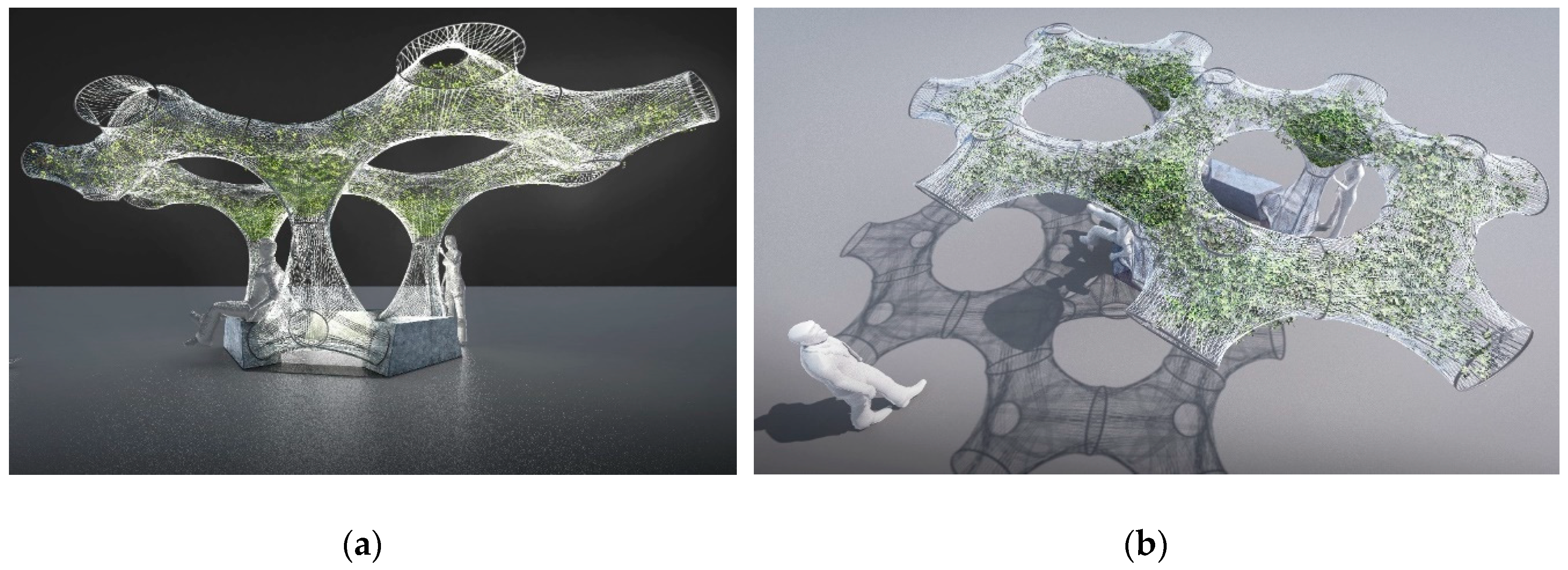
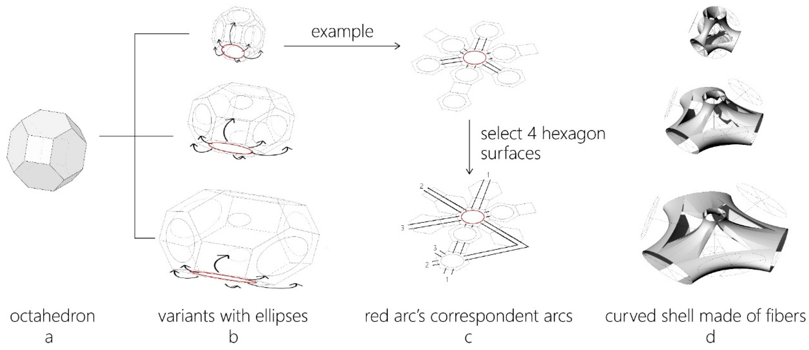
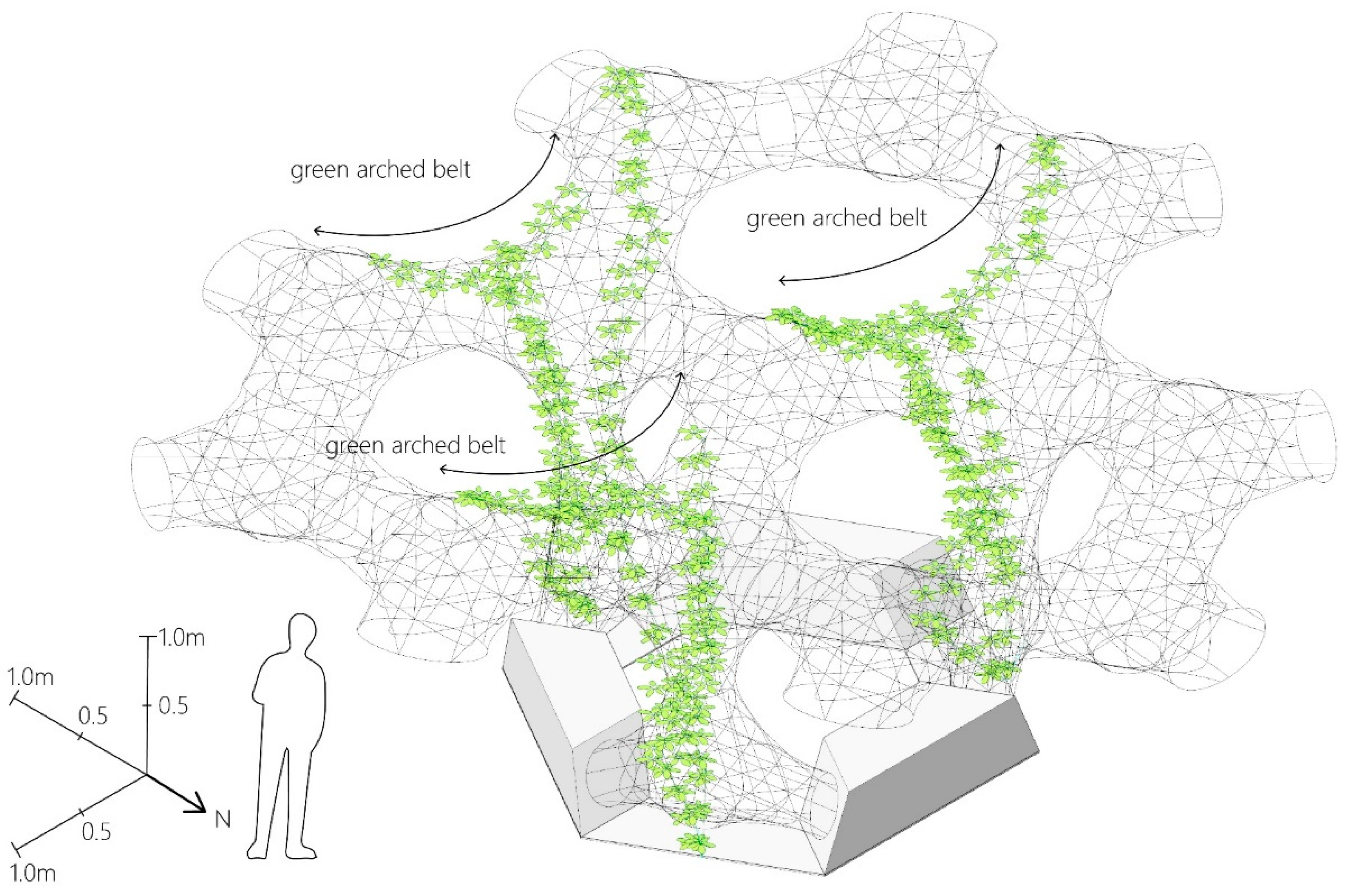
2.1. Concept Development and Design of the Overall Structure

The initial design of UMCC was developed by a team of eight students from architecture, landscape architecture, and civil engineering of the Technical University of Munich (TUM) in a studio project. The constructive goal was to develop lightweight elements that can accommodate plants. The structure should be able to adapt to different spatial requirements and local conditions, and plants should be integrated to improve the outdoor comfort. The former works by FibR and the Institute for Computational Design (ICD) at the University of Stuttgart [15] and the work of research group Baubotanik at TUM [16,17,18] were introduced to the students before the group was divided into three sub-groups working on individual concepts. One proposal was finally chosen for in-depth design and realization. The selection criteria were spatial-aesthetic quality, innovative use of parametric design possibilities, and robotic manufacturing technology, convincing integration of the plants and feasibility with regard to production, transport and assembly. As shown in Figure 1, the chosen design for the prototype is a lightweight structure made of fiber composite elements hosting the plants, standing on three wooden foundations that serve also as benches. With this configuration, the structure is intended to act as an “artificial tree” by generating a heterogeneously shaded space that invites people to meet and gather. Unlike the ICD/ITKE Research Pavilion 2013/2014 [15], where glass and carbon fibers were deployed, only glass fibers were used for UMCC. The reasons for this were, firstly, that the bright and semi-transparent glass-fiber structure forms a clear contrast to the dark green foliage of the plants and, secondly, that the light-conducting properties of the glass fibers were utilized for night-time illumination (see Section 2.4). Furthermore, the use of only glass fibers helped to keep the costs of the prototype comparatively low.

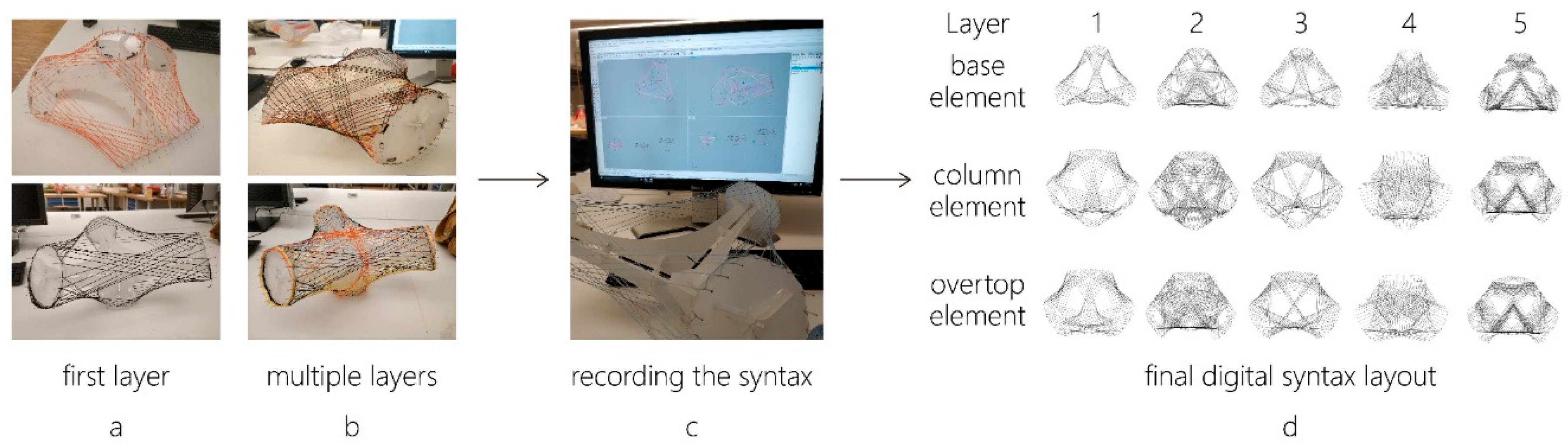
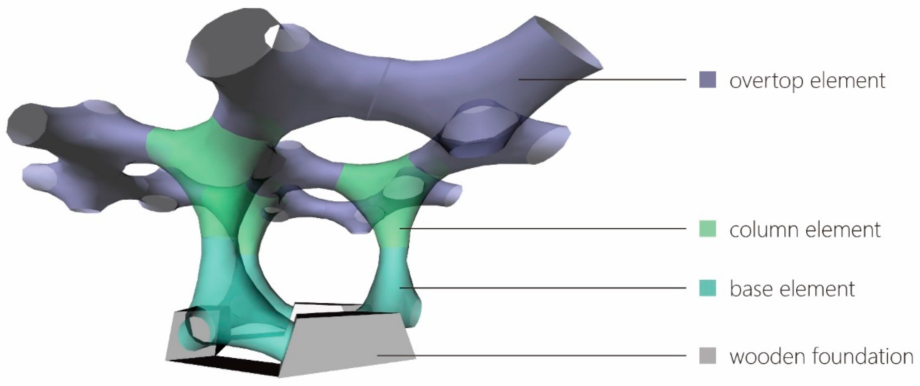
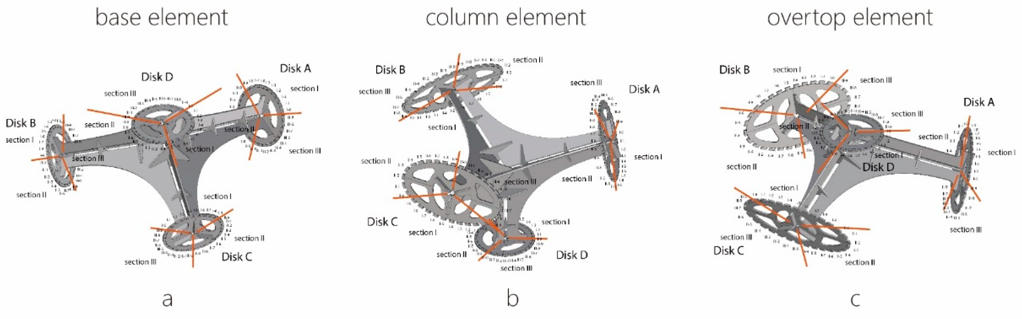
2.2. Design of the Modular Elements

As shown in Figure 2, a truncated octahedron was chosen as the geometrical base of the UMCC (Figure 2a). The shape is a honeycomb with cells that fill a 3-dimensional Euclidean space without gaps [19]. This enables easy permutation and combination of elements. Variants are made by expanding the octahedron in certain axes (Figure 2b). Circles (respectively, ellipses) are drawn on four of the total eight hexagon surfaces of the octahedron. Each circle is divided into six arc sections corresponding to six edges of their hexagons. These arcs have fixed spatial one-to-one correspondences in the octahedron (linked by double lines in Figure 2c). A doubly curved shell geometry emerges between the described elliptical boundary curves by winding the fiber bundles in a specific sequence (Figure 2d). In the concept phase, it was suggested that these geometrical parameters are varied piece-by-piece to create highly specific spatial conditions and functionalities like sitting, screening, and shading. To build the first prototype of UMCC, however, the total number of elements and the shape complexity were reduced in consideration of cost and time limits. As shown in Figure 3, the simplified prototype for manufacture consists of only three variants: three base elements, three column elements, and ten overtop elements which form three ring shaped canopy-like shading areas.
The fiber syntax (sequence of weaving) is key to the appearance and structural performance of the fiber shells of the elements. A sequence of multiple winding layers ensures that all desired performance goals are integrated in the final building component. A series of initial scaffolding sequences define the desired geometry and curvature, while the majority of the anisotropic fiber material should be oriented along the primary load paths. Additional winding sequences ensure sufficient cross linking and bonding between the fiber layers. Careful calibration of these layers allows to meet the structural and process dependent goals with the minimal required material and production time. The main supporting elements require more layers to bear the loads while low-stressed elements should have as few fibers as possible to save material and weight. Based on estimations and qualitative Finite Element Analysis (FEA) of potential forces (Figure 4) as well as on the experience and empirical knowledge of FibR, the base and column elements and the central overtop elements were reinforced by a higher number and thicker fiber bundles while the peripheral overtop elements were made as light as possible. How the winding sequence affects the final result is hard to simulate in a digital model. Therefore, the syntax was developed by crafting 1:10 physical models of the winding frames. Wool threads instead of the glass fiber bundles were used to test the winding syntax. The winding syntax then was rebuilt by polyline paths from one anchor point to another in digital models (Figure 5), which served as input for the robot path generation. The first layer directly connects corresponding arcs on the ellipses (Figure 5a). The following layers are more twisted patterns between the arcs and mostly rely on previously laid fibers as scaffolding. Their interaction and prestressing ensure a stable bond between the fiber layers and contributes to the forming of a curved shell geometry (Figure 5b). Such syntax results in a densification around the edges, what can be considered as beneficial since it reinforces these typically highly stressed areas.

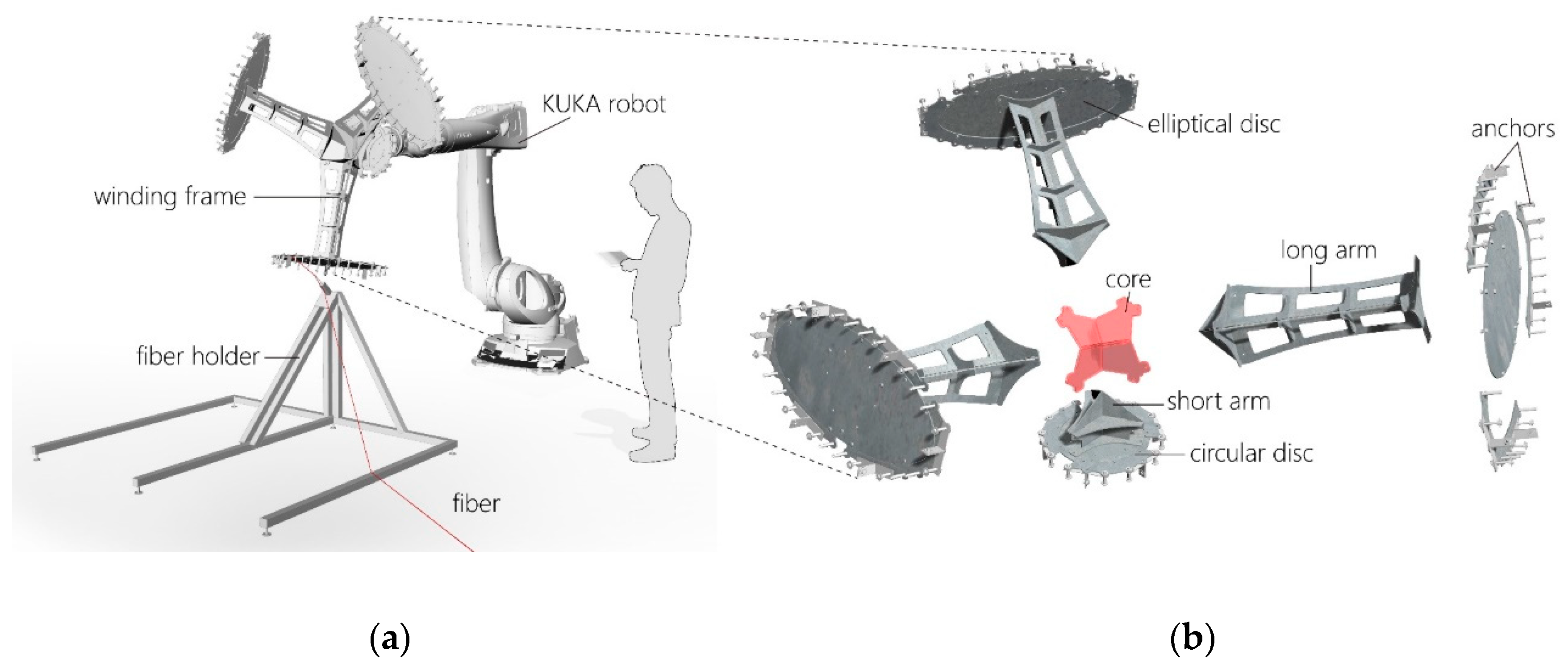
2.3. Development of the Winding Frames and Manufacturing of the Elements

The overall manufacturing process of the fiber composite elements, as fiberglass by FibR, consists of three steps: first, configuration of the modular winding frame and generation of the component specific robot code according to the previously developed winding sequence; second, robotic filament winding of resin impregnated fiber strands; third, curing and tempering of the fiber composite material. Only after the third step does the compound structure gain sufficient strength to become self-supporting and load bearing. Therefore, a dismountable, re-usable and re-configurable supporting frame is required to hold the fiber composite material during the winding and curing process. This winding frame should have sufficient deforming resistance against the weight of the fiber plus resin and especially against the tensions which occur during the winding process.
For manufacturing the UMCC specifically, developing the winding frames in the geometry of the elements was difficult as four elliptical (or circular) discs should be fixed to no perpendicular planes. Figure 6 shows a principal solution: each disc is held by an arm which consists of three non-coplanar joists. These joists are accordingly coplanar with one joist from each other disc. Four arms assembled together lock the discs in the required spatial positions. The supporting frames were finally made of laser cut steel plates which were welded into the specific frame elements.
The detailed design for the winding frame takes dismantling and economic aspects into consideration (final outcome in Figure 7). The solidified fiber structure completely encloses the frames (Figure 7d). To remove the frame, the arms and discs therefore must be dismountable into smaller elements that can be passed through the openings (Figure 7f). To produce three different winding frames with minimum material, the frames are designed as modular (Figure 7e): by combining different modules, the three different frames needed for the production can be created. These modules include the welded core onto which short or long arms can be attached, which themselves can hold circular or elliptical discs (Figure 7b). The frame for the base elements consists of three long arms and one short arm with only circular discs; the frame for the column elements consists of four long arms with three elliptical discs and one circular disc; the frame for the overtop elements consists of three long arms and one short arm with three elliptical discs and one circular disc (Figure 6).
The actual processes for manufacturing the 16 elements in the three described variations took two weeks. For each element, the metal frame was firstly assembled, then tubular aluminum sleeves were placed on the disks where fiber bundles should be fixed or where they should turn winding directions. In a similar way, galvanized steel brackets were integrated, which later serve to connect the individual elements with each other (Figure 7g). The winding frame was then installed on a KUKA industrial robot at the disk with the shortest arm (see Figure 7a,c); The movements of the robot arm were controlled in such a way that resin-impregnated glass fibers were wound on the frames following a digital path input; after winding, the fiber structure together with its frame were sent to a thermostatic chamber for curing and tempering at a stable temperature of 60 °C Celsius; finally, the winding supports were dismantled from inside the fiber structure.

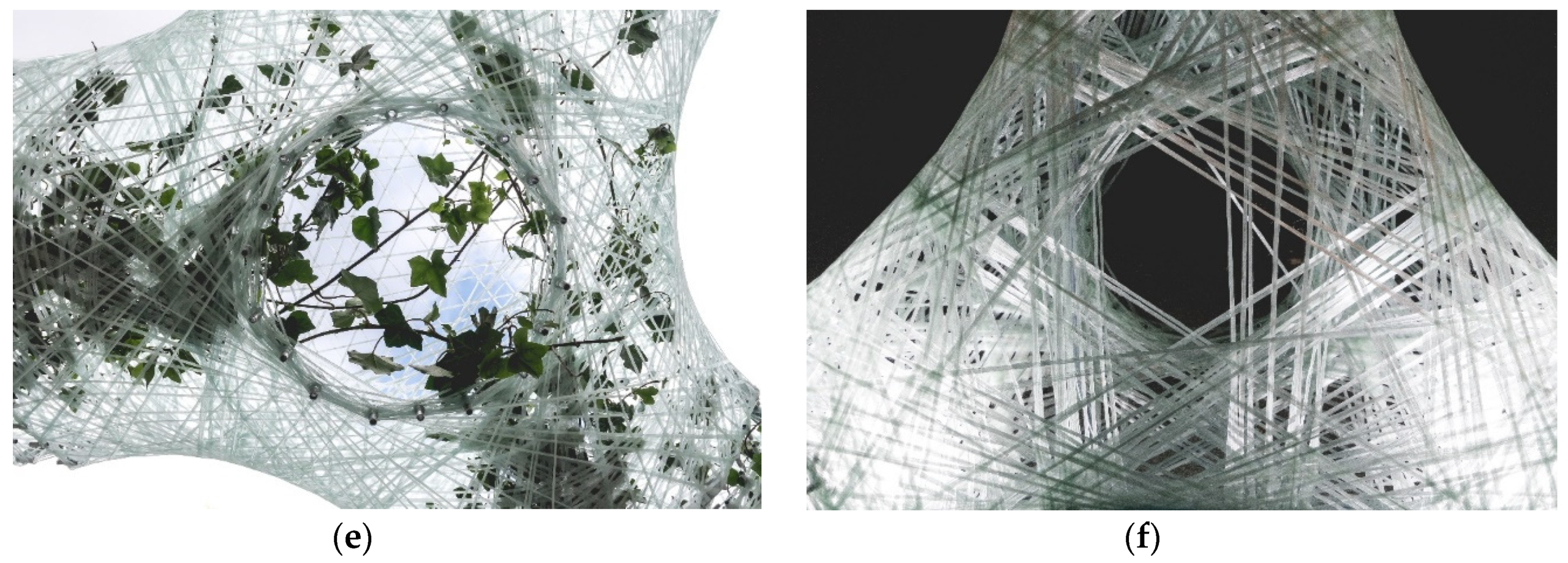
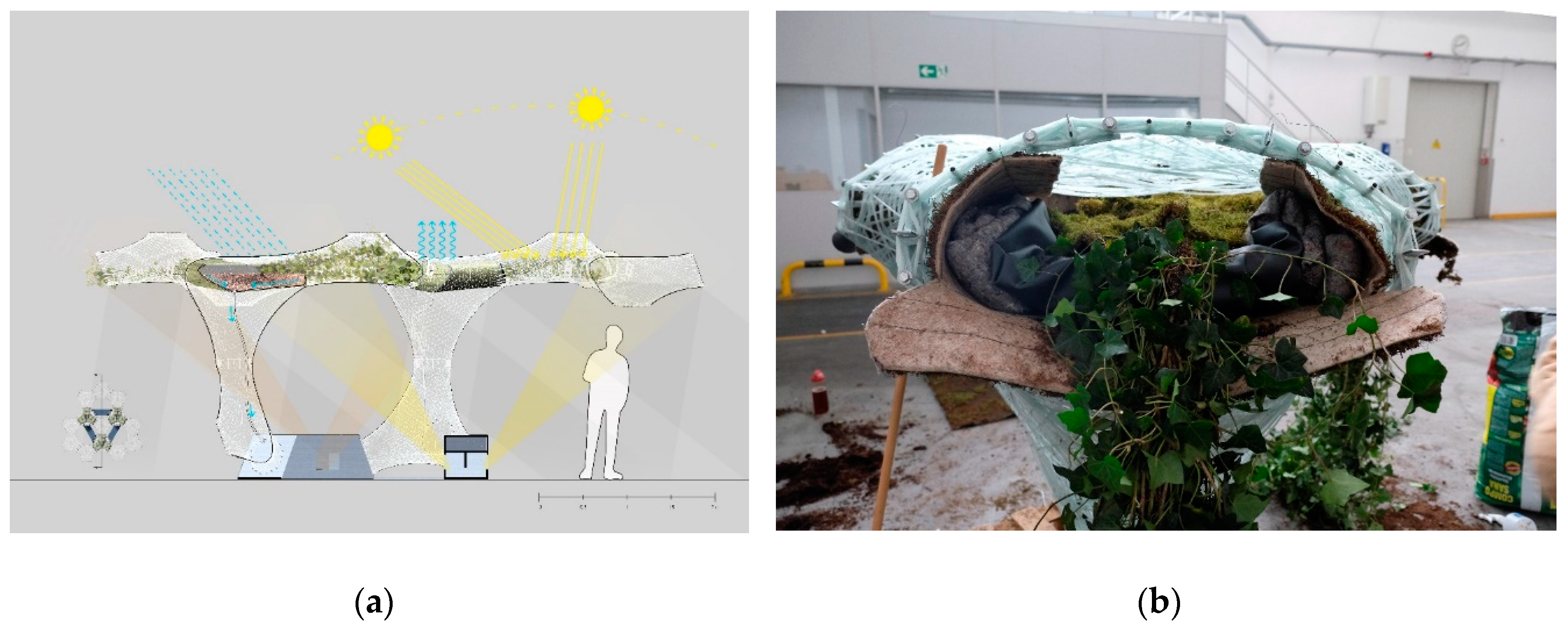
2.4. Planting And Lighting Design for the Temporary Installation

At the concept stage, the main idea was to plant climbers at the bottom in the box-like wooden foundations. As they grow, these plants were supposed to climb up to the overtop elements and extend their branches inside the fiber structure. Combinations with herbs or mosses at the column elements were also taken into account to create an impression of “a forest inside the city” and to enhance biodiversity. The selection criteria for the climbing plant species were firstly, frost tolerance as they were scheduled to be exhibited outdoors at Frankfurt am Main in March for a week, where the temperature could drop below zero degrees Celsius; secondly, the maximum length available on the market because the temporary installation doesn’t wait for the plant’s growth; and thirdly, the fact that the plants should have foliage when installed. An evergreen species was sought.
The only species that meets these requirements is ivy (hedera helix), the maximum length available in nurseries being three meters. With such length, the ivy leaves would not reach the central canopy element from the ground. Therefore, a compromised solution was implemented for the exhibition purposes: a planting area was installed in the upper part of the column elements on a wire mesh that was spanned between the fiber structure (Figure 8a). This installation consists of a pre-cultivated moss mat, an EPDM (ethylene propylene diene monomer) plastic sheet as a waterproofing layer, a root protection mat, and a mixture of expanded clay and garden soil (Figure 8b). Three ivy plants were placed in each of these three planting areas, the plant shoots were manually arranged in the overtop elements. For the relatively short-term installation, no irrigation system was installed; watering took place by hand. This solution made it possible that the shoots reached all areas of the overtop elements immediately. At the same time, this arrangement had the advantage that the lower parts of the structure—approximately up to eye level—remained free of plants, thus demonstrating how light and delicate the supporting structure actually is.
In addition to the planting design, the lighting design and the night-time effect played an important role. During the design phase, different possibilities for integrated distribution of LEDs within the fiber structure during production were discussed. However, this was later ruled out due to the high technical complexity and the modular design which would cause a great deal of electrical interlocking. Instead, an attempt was made to use the light-conducting effect of glass fibers. For this purpose, two LED spotlights were installed in each wooden foundation, which illuminate the lowest fiber elements, from where the light spreads over the entire structure by conduction and reflection. In addition to this lighting equipment, the wooden boxes were filled with concrete slabs to act as a mass foundation, avoiding mechanical anchoring to the ground.

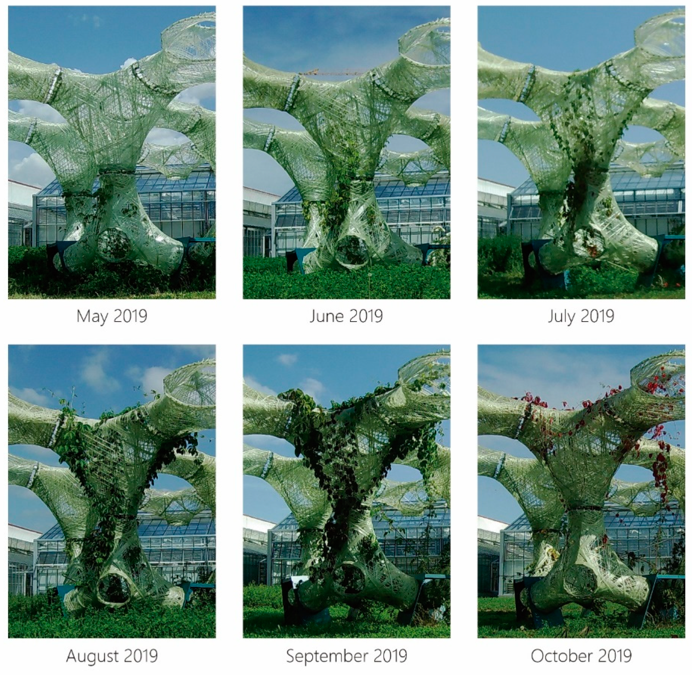
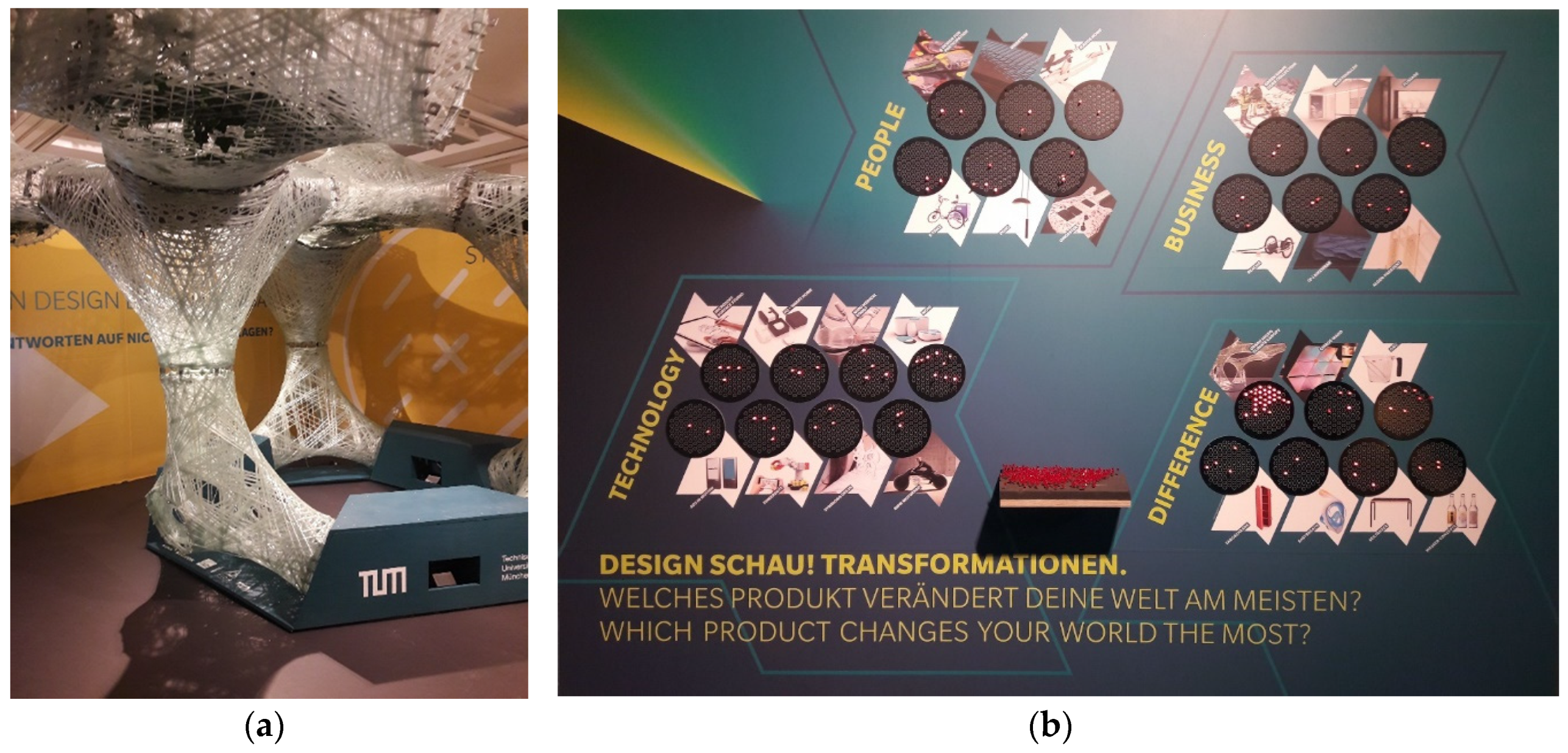
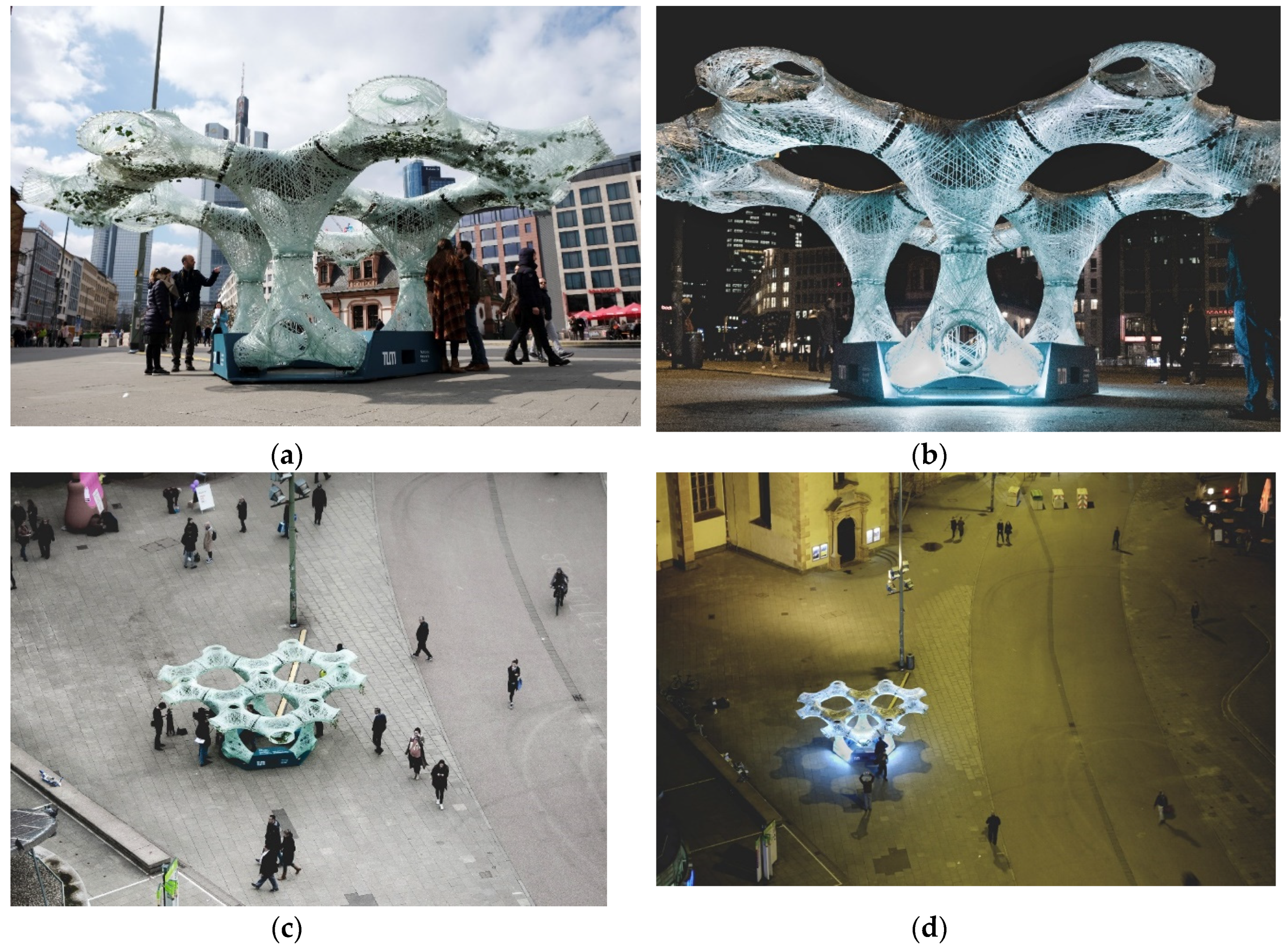
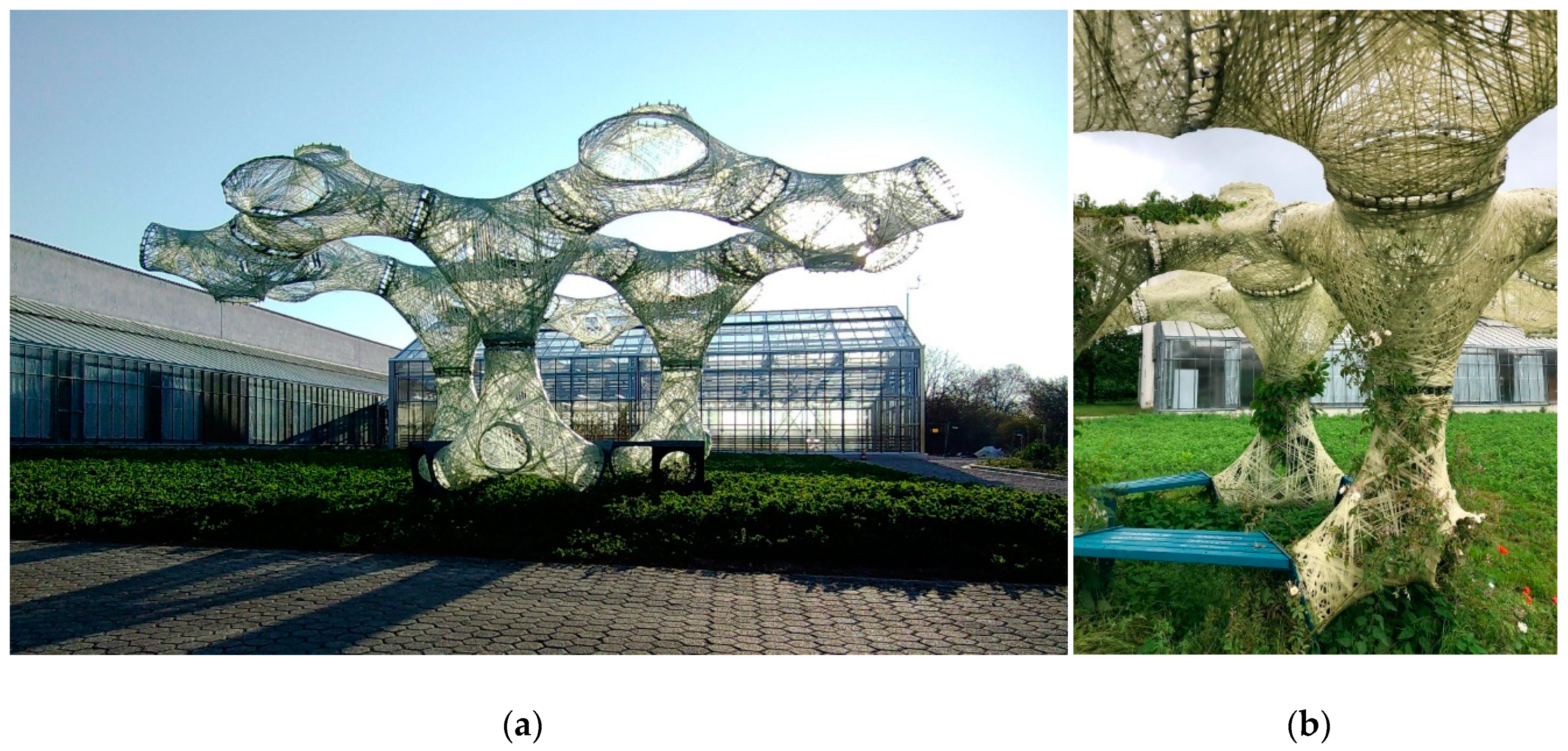
2.5. Temporary Installations and Their Perception

As mentioned in the introduction, the UMCC prototype was presented to the public in the context of two different events. The first installation took place at the Munich Creative Business Week 2018 in the German Museum. The aim of this indoor exhibition was to demonstrate the principle approach by presenting some assembled elements (Figure 9a). When visitors were polled with the question “which product changes your world the most?” in the first two day of the exhibition, UMCC received by far the most votes among the exhibits (Figure 9b).
The first outdoor and complete installation of the UMCC took place at Hauptwache, Frankfurt in the context of the biennial for light art and urban design LUNINALE. The overall structure with its 16 fiber elements, the three wooden foundations, the plants, as well as the lighting was installed within two days. During the installation process, about a dozen passers-by came close being curious about the materials and techniques. During the week of the LUMINALE, UMCC was often seen surrounded by attracted visitors who also used the place to rest and gather on the base elements. At night, the illuminated fiber structure stood out from the plaza context, serving the site as a unique urban furniture (Figure 10).

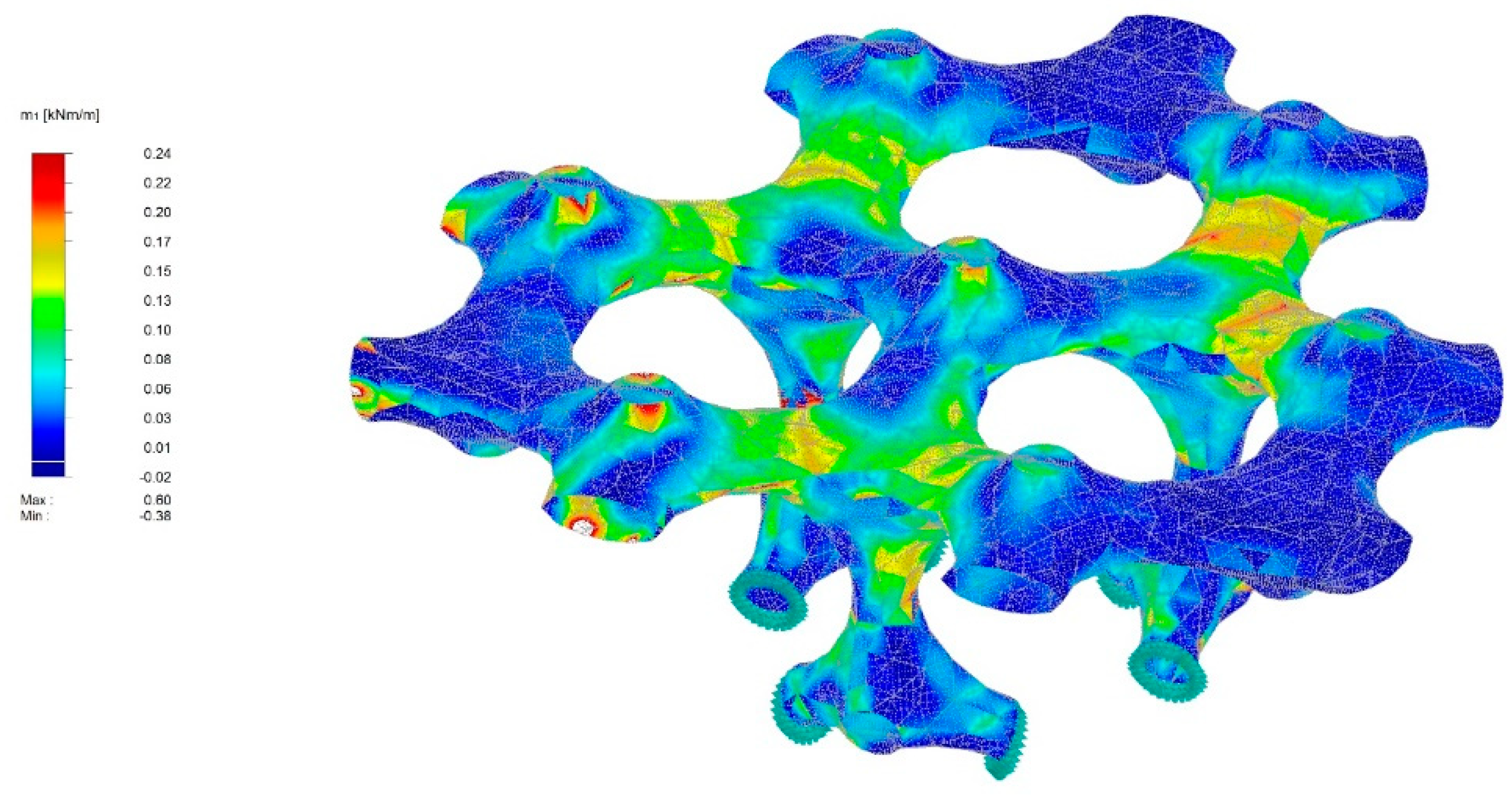
3. Reflection of the Outcome

As the visitor poll during the Munich Creative Business Week clearly demonstrates, the idea of combining an innovative design and production process with green architecture can be regarded as an overall convincing approach. During the design process it was confirmed that various design requirements (e.g., different requirements regarding the load-bearing capacity or transparency) can be addressed by variations of the winding pattern, the thickness of the fiber bundles and the number of layers. The specific characteristics of the compound fiber structure in the form of double curved surfaces achieved both functional and aesthetical standards. Deep comprehension of the design and fabrication technology enables utilization of the fiber material.
In contrast to the design and production of these technical parts, using plants as integral natural elements in the design posed a particular challenge. Unlike the technical components, plants are not finished elements, but develop over time based on their inherent growth patterns in reaction to the setting’s growth factors (compare e.g., [18,20], see also [21]). However, due to the need to create a representative pavilion that can be exhibited in minimal time, plants had to be used in exactly that way here: the ivies at the temporary exhibition were not demanded to really grow. In the design process, this was reflected in the fact that, for example, the size of the plants at the time of installation and not their growth characteristics were considered as decisive design parameters. In a long-term application, however, the question of how the plants will grow in the geometrically complex structure that offers a multitude of possible growth paths and complex growing conditions is much more important as it is decisive for the spatial, aesthetic, and microclimatic effect.
In order to design projects like UMCC in such a way that they achieve high microclimatic effects (e.g., through optimal shading or maximal evapotranspiration) it is therefore necessary to forecast plant growth during the design process and, building on this, the microclimatic effect of the plants (as done e.g., by [22] or [23]). In a next step, the findings from such simulations can then be used to modify the structure in an iterative design process in such a way that preferred growth pathways are created that guide the growth in desired directions. Accordingly, the aim of a comprehensive design approach in living architecture must be that the specific characteristics of the plants become the starting point for an iterative design approach.

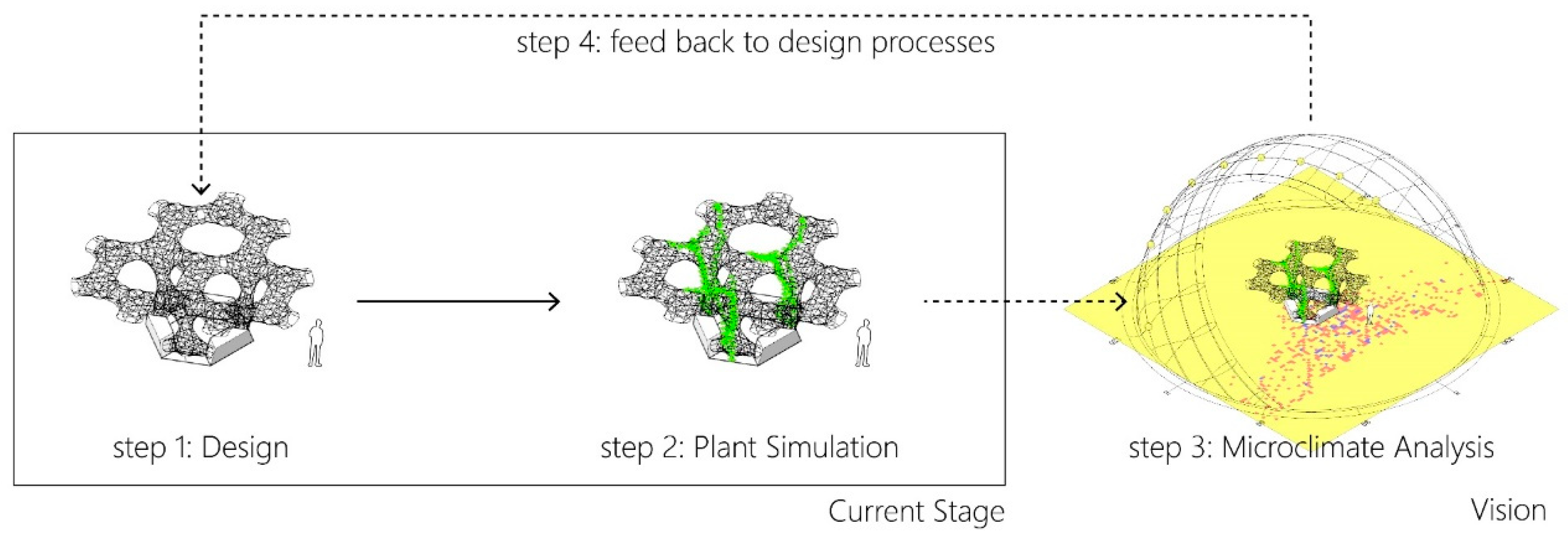
4. Moving towards an Iterative Design Approach

4.1. Prerequisites to Integrate Plant Growth in a Parametric Design Process

A design approach in which the growth behavior of plants is integrated in an iterative design process requires at least four steps (Figure 11): (1) a parametric design of the technical structure (2) a plant growth simulation to forecast the development of the plants under the given conditions; (3) an analysis of the plant-technical hybrid system’s performance; (4) a feedback system which allows—on the basis of the performance analysis—to change the input parameters of the technical structure and thus the growth conditions of the plants in such a way that the desired performance is improved. These four steps have to be repeated until an aimed indicator setup is reached (e.g., the shading effect in Figure 11). This iterative approach can be seen as a pre-occupancy evaluation (unlike post-occupancy evaluation [24]) that evolves the proposal already during the design process. UMCC offers an essential prerequisite for this approach since it is based on a parametric design methodology (step 1). The geometry as well as the winding syntax of the elements can be altered by altering input parameters which would drastically change the growing conditions for plants such as the possible pathway a climbing plant could follow. Regarding step 3, evaluating indicators such as building’s environmental impact [25] or material properties during digital fabrication [26] have been covered in previous studies. Considering microclimatic effects as indicators, existing environmental engines like Ladybugs [27] and ENVI-met [28] provide models for common microclimate analysis, such as shading effect based on the sun path and radiation. To adjust the input parameters in step 4, an enumeration method is feasible when parameters are given small ranges and strict rules (i.e., Table A in [25]). To deal with combinations of a larger range of parameters and multi-criteria problems, generative design is a solution to vary parameters partly randomly based on a historical vector graphical database system [29].
Regarding step 2 of the planned iterative design process, corresponding functional-structural plant models (FSPM) are required to depict plants’ 3D presentation based on physiological processes [30]. Although FSPMs are studied for different purposes (e.g., for peach gains [31], for crop growth [32], for animation [33]), no systematic description exists for simulating climbing plants growth on a geometrically complex network like supporting structures. This is why a first approach of a novel functional-structural model for twining plant growth on 3D trellises is introduced.

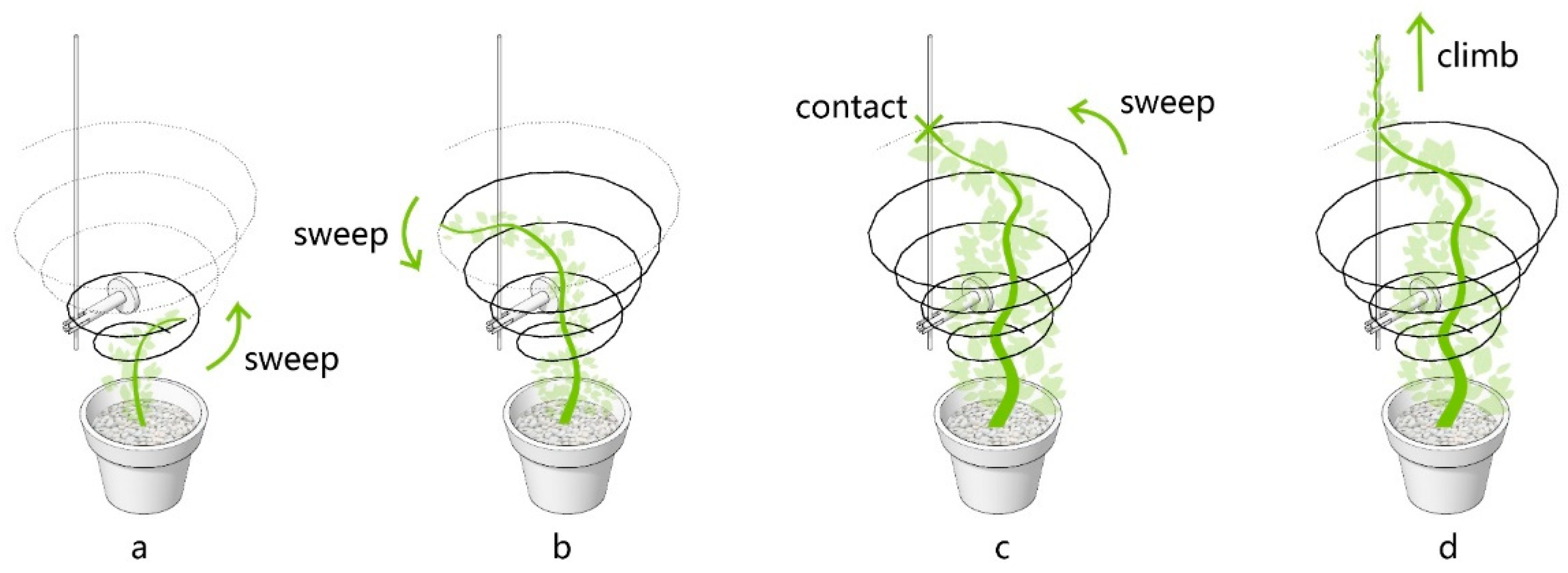
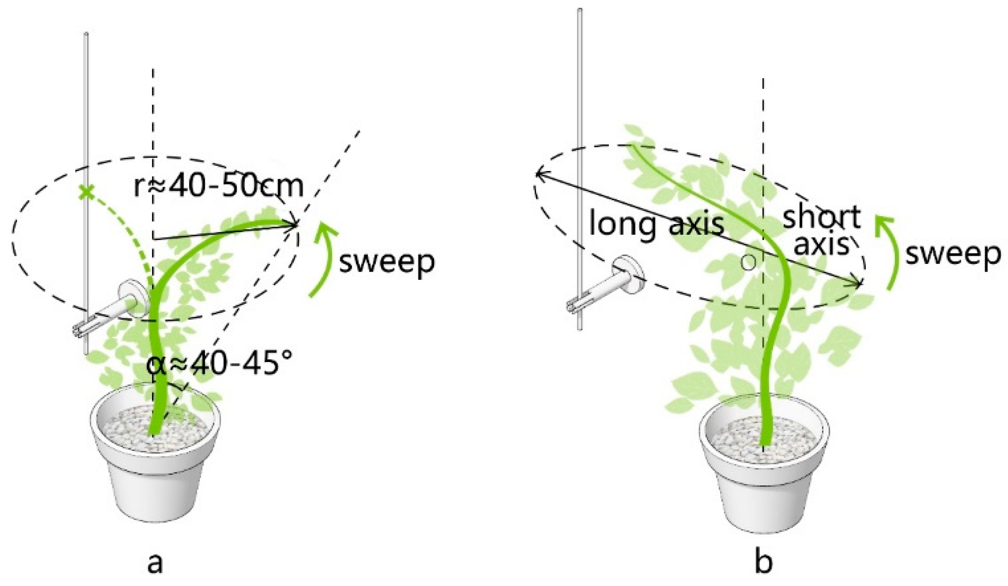
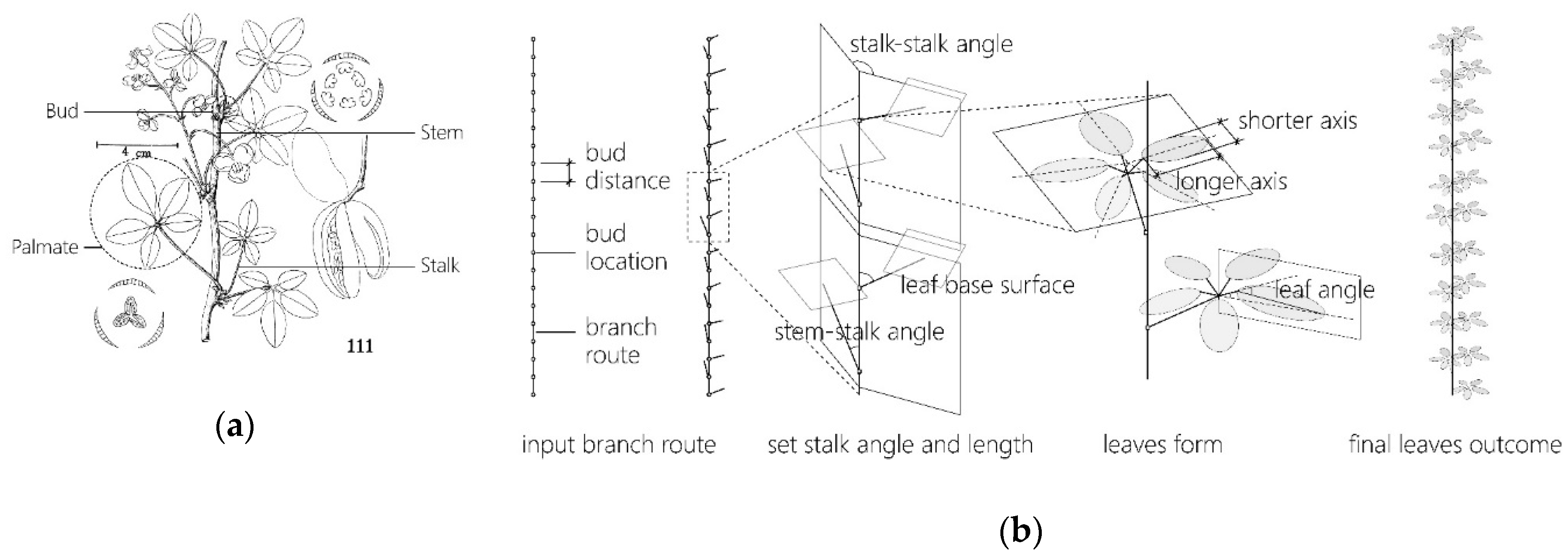
4.2. Physiological and Morphological Basis for this Simulation

A functional-structural model (FSM) for plant growth is a combination of a process-based model (PBM) that is developed on plants’ physiological processes and a structural model that defines the geometry [30]. FSMs can be achieved by either adding physiological information to a structural model or in the opposite, increasing the structural detail from a process based, functional model [30].
Starting from the structural side, the most commonly used models for plants in general are L-systems [34,35,36]. Particularly, climbing plant models adapted from L-systems can be sensitive to some environmental factors, for example light [37] or gravity and collisions [38]. By introducing physical engines, the branches of the climbing plants acquire interactions with the wind [39]. These models are well applied in the computer game and film industries. For such applications, tools with improved handling for end users have been developed [39]. With these features in environment sensing, these tools are powerful for virtual rendering; however, they are not feasible for predicting climbing plants’ pattern within a performance-oriented design process. The gap between these revised L-systems and potentially correct forecast of climbing plants’ growth is large. Therefore, a growth simulation for UMCC requires a stronger physiological basis.
Starting from the functional (process based) side, climbing plants can be categorized according to climbing mechanism: plants that twine at stem around a support; plants that have clinging roots or tendrils with adhesive pads; plants with twining petioles or tendrils; and plants with thorns or other hooked structures [40]. In our simulation, twining plants are the only focus to narrow down the problem. There are two crucial characteristics of twining plants’ behavior: firstly, when twining plants grow without prior attachment to a support structure, searcher shoots actively search for adjacent supports to continue growing along. Secondly, shoots searching for their next anchorage point sweep through the air in a helix, called circumnutation (Figure 12a). One rotation usually takes 1–2 h, but both the helix diameter and the circumnutating rate vary with species and environmental conditions [40,41]. Using modern time-lapse video methods, it has been found that changes in aspects of the circumnutation (radius, orientation, and speed of rotation) are a plant’s visible reaction to certain environmental conditions [42]. Reaction to stimuli like light and gravity were studied using particular species like Morning Glory (Ipomoea nil) [43]. Experiments have shown that rotational movement was modified into an ellipse with the long axis oriented towards the support (Figure 12b), perhaps due to negative phototropism [40]. Nonetheless, the physiology underpinning the phenomenon of circumnutation is still under investigation and there is, as yet, neither a universal model for circumnutation nor conclusions regarding the relationship between relevant stimuli and the twining behavior.
Prusinkiewicz et al. mention the possibility for a parametrized model of twining plants winding around a supporting pole using an L-system [44]. Adaptions to environmental stimuli are not involved in this study, and unlike pole-shaped structures that have a certain diameter, the thickness of the fiber glass bundles of UMCC is negligible. Therefore, this study is not directly applicable to simulating twining plants’ growth on UMCC, but it indicates a great potential to apply the circumnutating movement as a physiological model to twining plants’ growth: a searching shoot repeatedly moves its head from a current location in a spiral space to search for supporting structures that can be climbed on. The computational solution, accordingly, can use a polyline that connects touch points of the plant with the supporting structure in sequence to represent the main branch. Based on circumnutating movement affected by environmental conditions, the simulation presented here puts forwards a novel approach to generating a single growing path of a twining plant on a network like 3D supporting structure.
Circumnutating movements of twining plants can be very complex in relation to environmental conditions. This study focusses solely on and accounts only for two highly important factors: light and gravity, and the corresponding plant responses of phototropism and gravitropism. The following are preconditions for modelling:
(1)
The species considered must be a twining plant that uses searching shoots to find support;
(2)
Soil conditions including water, nutrition, and gas exchange are in idealized condition, not affecting the plant’ s performance;
(3)
The growing process requires support systems; stems cannot stand on their own;
(4)
Stems overlain on the same supporting locations or on previous stems are excluded;
(5)
No wind effects on the circumnutating movement are considered;
(6)
No plant diseases or extreme weather events that could interrupt the growth process are considered.

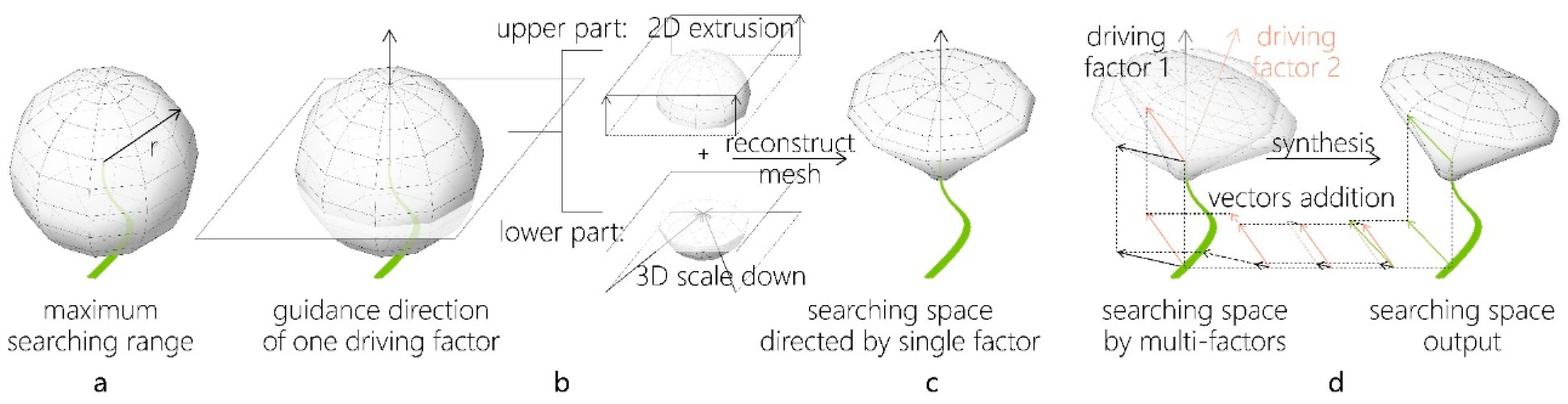
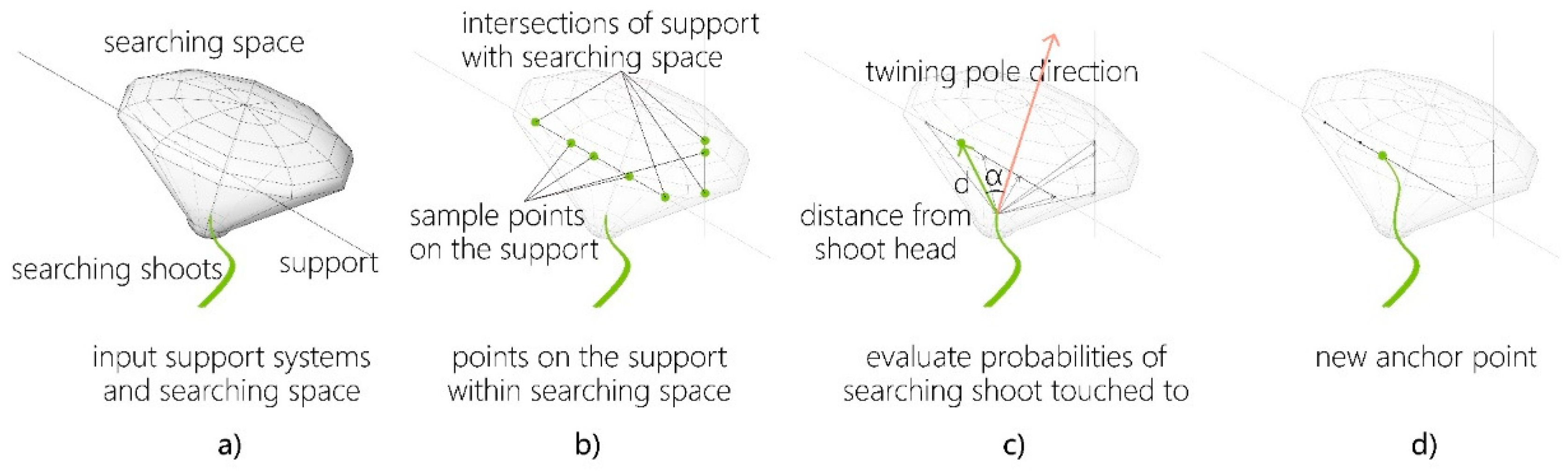
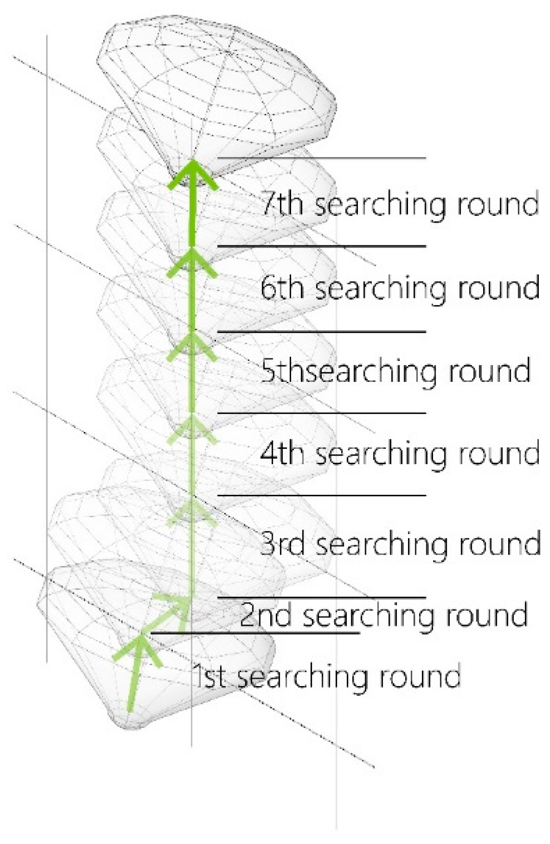
4.3. Core Models of the Simulating Process

In general, a simulation of twining plant growth should represent characteristics of all kinds of plants that show circumnutation as a main pattern of growth. To accomplish this task, two core models are suggested, namely the “searching space model” and the “climbing steps model.”
The “searching space model” describes how a searching shoot circumnutates to find a support (Figure 13). It is assumed that at each anchored point, a shoot head’s searching space is defined by the maximum searching range (a physiological limit) and the circumnutating behavior. The searching range defines firstly a maximum spherical searching space of the shoot (Figure 14a); Circumnutating behavior is an adaption to this searching space by driving factors. For example, if only directed by a single factor like gravity, the shoot head begins sweeping with a circle of smaller radius at lower height, and then moves higher (against gravity) with bigger range (Figure 13). Such movement results in a funnel-shaped searching space, which is seen as a mesh transformed from the original sphere (Figure 14b,c). In the same way, the searching space can also follow other circumnutation driving factors, e.g., light (either towards brightness or darkness). The “driving factors function” converts these driving factors into guidance directions. Most of these driving factors (and therefore guidance directions) vary depending on the anchorage point (position in space). The final searching space output is the weighted synthesis of all the funnel-shaped meshes by different guidance directions (Figure 14d). With this model, it is possible to modify “driving factors function” to simulate different species. Support sections positioned inside this final searching space can be found by the shoot.
The “climbing steps model” is a superordinate model consisting of iterative rounds of growth (Figure 15). Each round includes the “searching space model” as well as two functions, the “anchor selection function” and the “timed loop function” (Figure 16). Searching space is set at the beginning of each searching round where the searching shoot is anchored. A new anchored location is picked out within this searching space by the “anchor selection function.” This new anchor point acts as the base of the next searching round. All anchor points lined up in sequence shape the route of one branch.

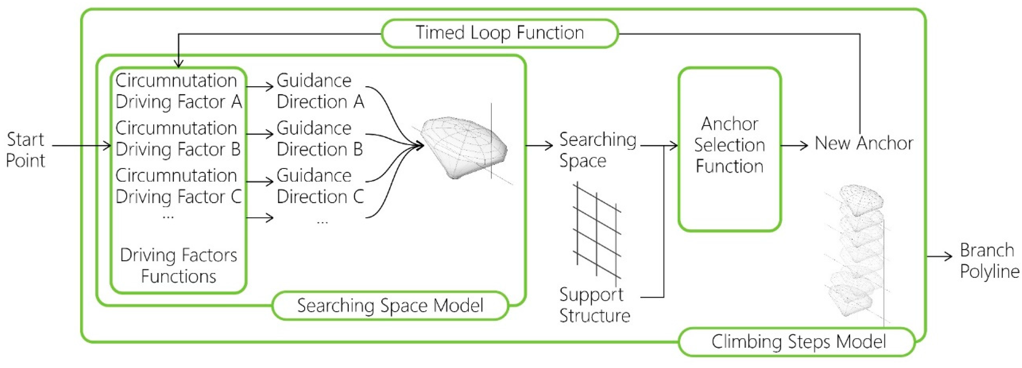
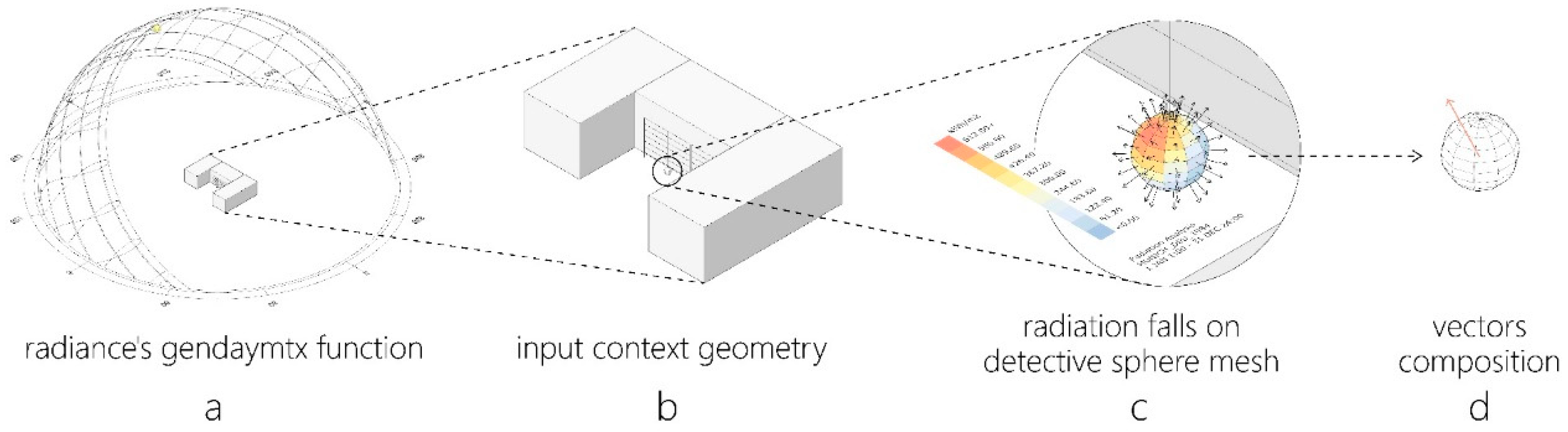
4.4. Simulating Framework and Additional Functions

Having framed the simulating process (Figure 16), definitions of the “driving factors function” and “anchor selection function” become crucial for the performance of this method. These two functions require strong physiological knowledge about specific species to work out reliable results. Presented in this paper are simplified setups to allow a preliminary completion of the program for a generic twining plant. It is expected that these functions can later be individually improved or adapted for specific species.
For driving factors function, two guidance directions of environmental stimuli are applied: gravity is a constant downwards direction (usually Z-axis) in a 3D working space. Light direction adopts maximum received radiation direction at the plant’s position. This is in our case calculated by using annually average sky matrix radiation data of Munich and the surroundings that may block the sun (Figure 17) [45]. Maximum searching range of the virtual generic plant is set to 0.5 m and the respective weighting of gravity direction to light direction is 0.2 to 0.8.
For selecting a new anchor point at the supporting structure within the searching space (Figure 18), as the shoot circumnutates in a helix, the probability of anchorage varies between points, depending on two evaluated characteristics. A point located closer to the shoot head (smaller distance d) is more likely to become the next anchor. Also, a narrower angle α (Figure 18c) between the central axis of the searching space and the line of connection from shoot head to evaluated point leads to a higher probability. Tests in this study input an equation cos α × 2.5 d to calculate a score for each proposed point. The point with the highest score is selected as the new anchor point in this searching round (Figure 18d) and becomes the shoot head of the next searching round.
Additionally, a “leaf pattern function” is introduced to roughly imitate leaf and bud distribution along the output branch route for visual effect. This is achieved by defining the bud distance, angles between stalks and stems, and elliptical shape of each palmate leaf (Figure 19).
Finally, the branching problem is overall a complex issue. In woody plants it is controlled by internal patterns (mainly apical dominance) and external parameters (e.g., lighting conditions, orientation in space etc. (see e.g., [46,47])). To overcome this complexity and to allow multiple branches in the simulation, a temporary working solution is suggested here which picks out some buds near possible unoccupied supports to start new branches. In order to avoid new branches overlaying previous ones, the later branch uses the evaluation equation cos α × 2.5 d + lg ( d ) instead of the original one for anchor selection, where d is the shortest distance from the anchor candidate to any previous branch.

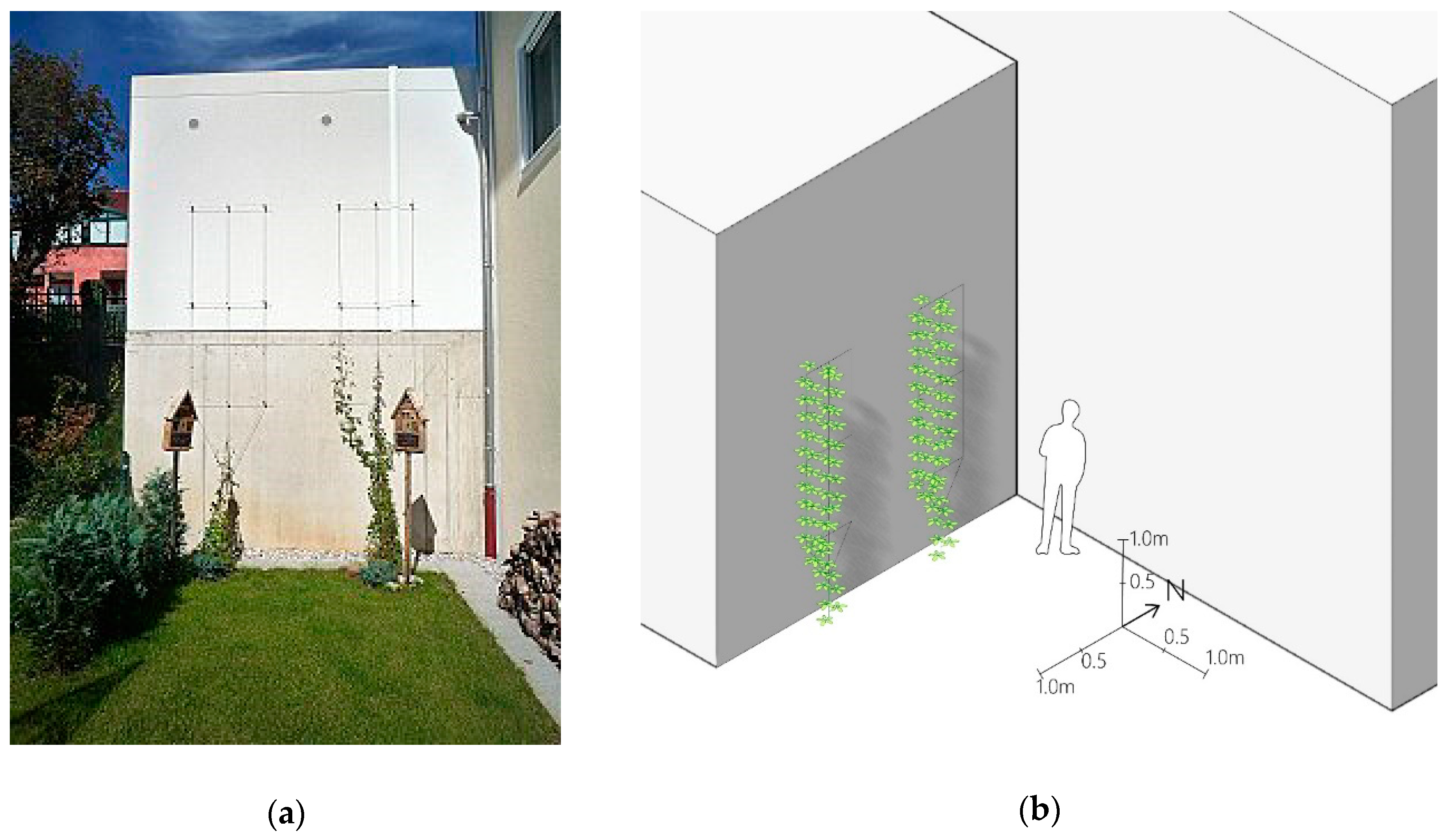
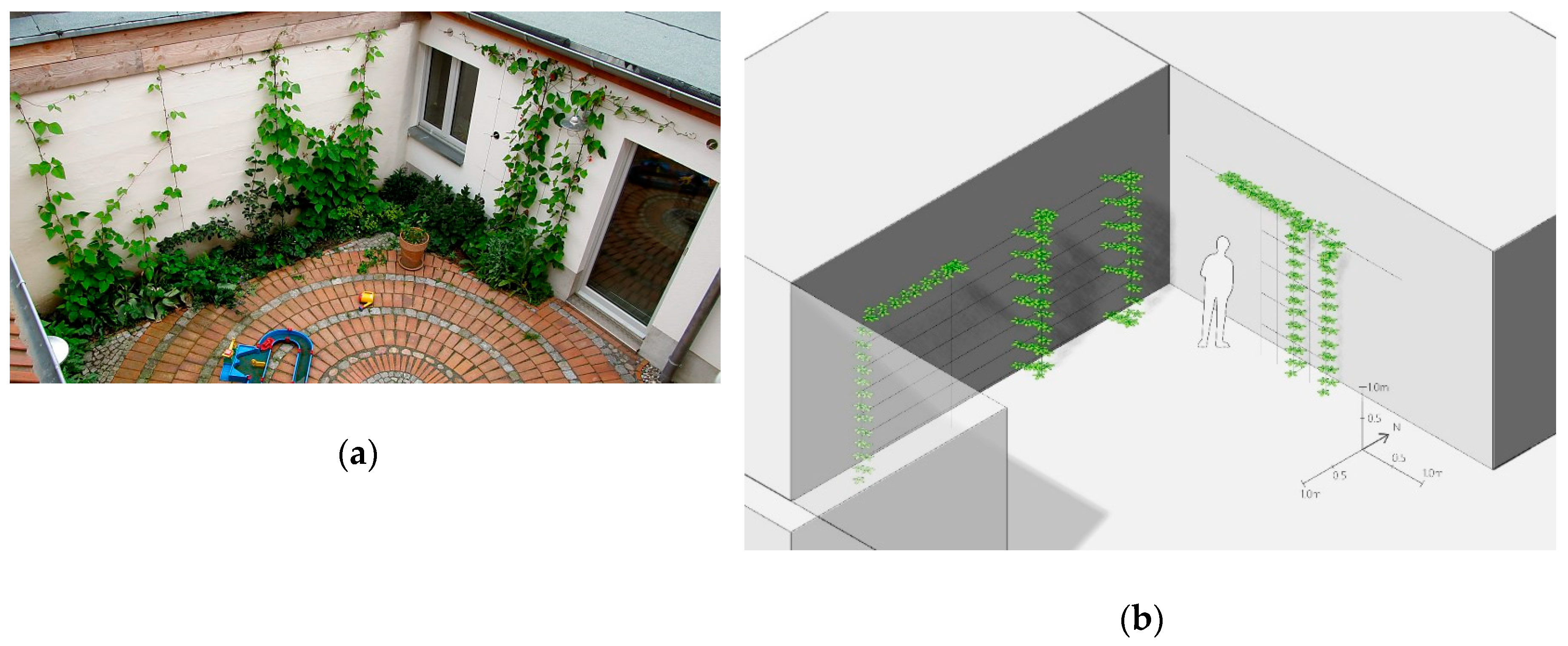
4.5. Plausibility Test of the Simulation Approach Using Case Studies

As already mentioned, all setups in Section 4.4 do not represent a specific species of twining plants, but instead a generic prototype. To make accurate forecasts for the growth of specific species these functions require further studies. To gain a preliminary understanding of the feasibility of the simulating model, virtual 3D models of existing situations are built where twining plants are growing on a trellis and compared the simulation result with the photos of the grown plants. (the testing scenes and source codes are available in Supplementary Materials) The results of two such plausibility checks are presented below.
In Figure 20a, two sets of the same support systems are installed on a building’s exterior wall next to each other. Figure 20b is the simulated result for the scene. Compass direction is added to the model without precise reference to the scene’s true orientation though a rough estimation seems to be appropriate here. In the model, the first stem grows on the southernmost support. The second generated branch that can’t overlay the previous branch climbs up along the middle support. This result shows how searching space affects branch route “decision” on support systems: owing to the buildings blocking sky radiation from the north and west sides, the most sunlight radiation comes from south and east in this scene. Therefore, among the three vertical parallel support lines, the southernmost one is most likely to be chosen by the twining plant.
Figure 21a shows two sets of grid support systems in a courtyard. A twining plant starts growing from the bottom of different vertical cables. Simulation results of this scene are shown in Figure 21b. Here especially, the simulated plants on the east oriented wall show interesting patterns. The two northern ones develop branches at each intersection point of the grid which grow all to the south. This can be explained by the orientation of the searching cone, which is oriented to the south here (Figure 22). The southernmost plant grows in an area which is heavily shaded by the building in the south. It does not show branches and grows straight upwards to the highest horizontal support. Along the vertical support, the search cone is slightly oriented to the north since this is the direction of the light under the southern wall’s shade. Nonetheless, this orientation does not lead to the growth of branches along the north oriented supports at the intersections. An explanation for this “behavior” is that the deviation of the searching cone is below the threshold of the branching function. At the top point, where the north-oriented horizontal support is the only possible growth direction, the plant turns right and follows this support. It is of interest that the plant stops growing at the middle of this top horizontal support. As the southern sunlight increases (and the shadow’s influence decreases), the searching space turns to the south (see Figure 22). Growth stops when the searching space does not include a viable point that avoids overlaying. In the simulation, the selected anchor point falls on an existing branch route. In the real world, twining plants indeed behave this way, making U-turns and climbing backwards along their own branches or may simply continue growing even though they are not reaching a better-lit space. However, the simulator does not currently allow stems to overlay, so the climbing steps model ends here.

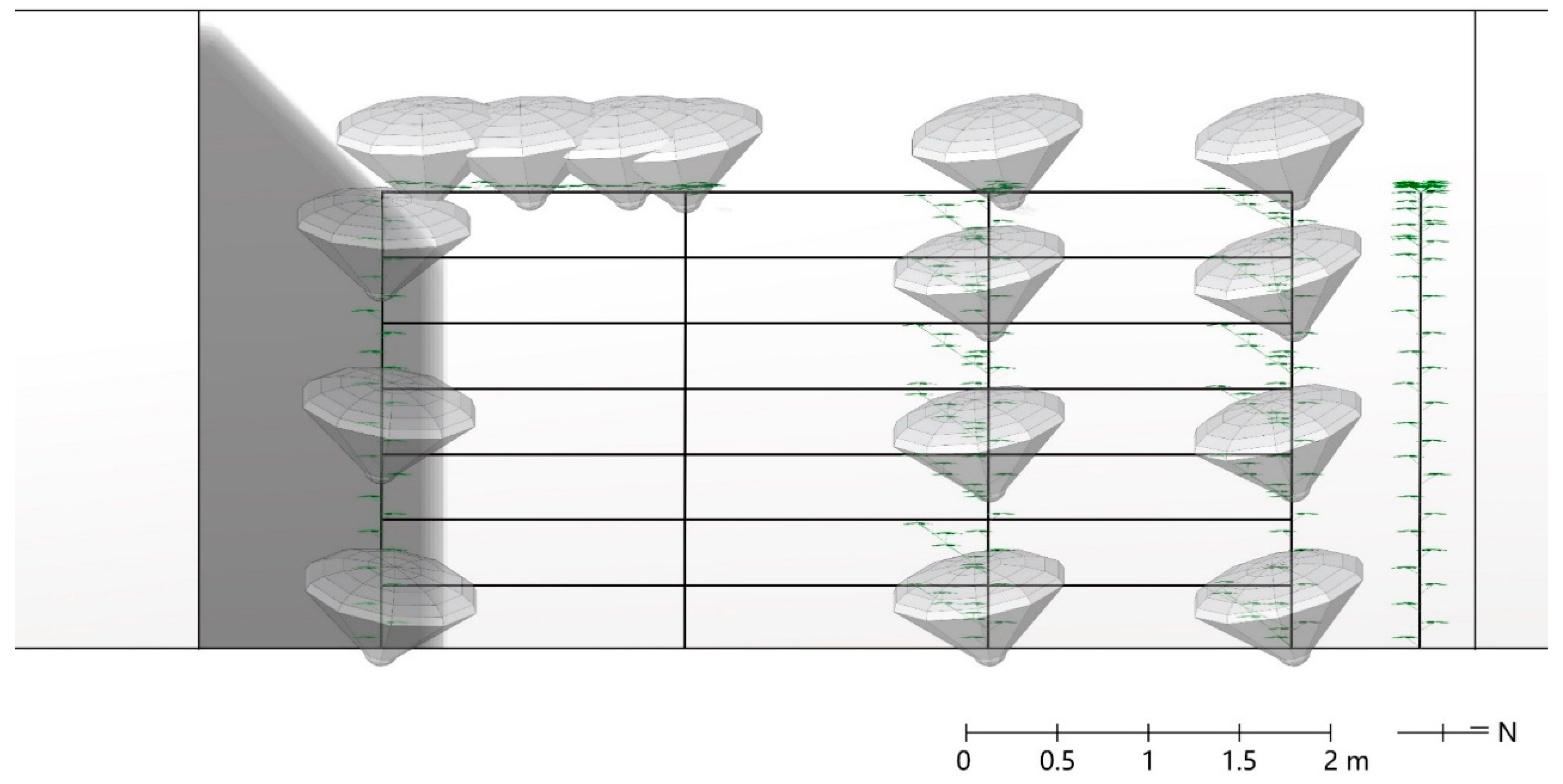
4.6. Growth Simulation on the UMCC

The fiber structure of the Urban Microclimate Canopy (as described in Section 2) has a great fiber density, which makes for a complex support structure and a high calculation load. Therefore, this simulation uses a simplified version of the original canopy, which only consists of around one tenth of the original support elements. However, an over-simplified structure may cause difficulties for shoots jumping over gaps between two canopy modules. A second simplification to keep calculation load low is that shading of the (very light and transparent) fiber structure was not simulated here. Radiation inside the canopy also cannot be simulated here. The result (Figure 23) is generated in two branching rounds, having three primary branches and nine secondary branches. All the branches climb generally towards the sun direction (south). As the canopy’s overhead modules form three tori, the stems climb around the edge forming green arched belts.

5. Redesign and Setup as a Long-Term Experiment

To acquire more knowledge about the real interactions between the artificial fiber networks and climbing plants during their growth, the structure was set up for long-term observation at a test field at TU Munich in September 2018. The fiber elements were reused without any changes while the wooden box-like foundations were replaced by a foundation of precast concrete and arch-like steel elements with wooden coverings (see Figure 24). Within each of these elements, two climbing plants were planted and their shoots guided into the lower, round openings of the fiber structure. Three distinct types with different climbing patterns were used: Virginia creeper (Parthenocissus quinquefolia) as an example for a plant with tendril adhesive pads, Bavarian Hardy Kiwi (Actinidia arguta ‘Weiki’) as an example of a twining plant, and the rambler rose Bobbie James (Rosa ‘Bobbie James’) as an example for a hook climber.
This installation has been set for about 20 months as this article is written, which cannot yet provide meaningful results but only first impressions. At least five years of growth observations are planned. What is visible so far is that the Virginia creeper is developing very vigorously, weaving in and out the fiber glass structure seeking supports. The shoots reached the top of the structure easily within the first growth period in 2019. Some shoots could not find hold on the structure and were hanging down by up to one meter (Figure 25). The Hardy Kiwi grew much less in the first year and the few circumnutating shoots could not find their way through the structure or could not loop around fiber bundles. Therefore, they fell back and the plants did not grow out of the base element. It was not until May 2020 that longer and stronger shoots emerged, which were able to find their way through the openings in the fiber structure, to find hold and continue growth upwards (Figure 24). In contrast, the roses grew very vigorously from the start. However, only a few, rather short shoots grew as intended within the fiber elements. The majority sprouted vertically at the base and one shoot reached the overtop element directly from there without any further support. In winter 2019/2020, the hanging shoots of the Virginia Creeper were removed or inserted into the structure. The shoots of the roses growing outside the fiber elements were also removed or cut back for the most part.

6. Discussion and Conclusion

This paper documents the UMCC project from design to manufacture, simulation, and installations. It was carried out based on a research by design approach in the field of living architecture. The design and temporary installation of UMCC with its advantages and disadvantages has been discussed in Section 3. The integrated design approach that was developed on this basis required a new simulation framework for the growth of climbing plants. The simulation results suggest that the framework is feasible for reflecting the phototropism and gravitropism in climbing plants’ growth on fiber-like supporting networks. However, the simulation tool presented here must be seen as a first step, which is as yet not able to predict climbing paths close to reality. The limitations lie in the exclusion of branch overlay, the fact that the anchor selection function is lacking a physiological basis and that the leaf pattern, bud distribution, and branching problems are not deeply analyzed in this simulator. Also, other environmental factors like wind need to be taken into account. Nevertheless, the simulation method put forward in this paper shows a novel framework and its potential in climbing plant simulation. While some obstacles remain, a combination of the new approach and existing simulators that cover aspects such as branching in high detail appear promising (compare e.g., [51]).
Furthermore, experiments are needed to derive the relevant parameters for different climbing plants. Findings in this regard for the example of Hardy Kiwi will certainly be provided by the long-term observations in a few years’ time. Regardless of the relatively short growth period of 20 months, this test set-up already provides some qualitative findings and draws attention to aspects that need to be taken into account when further developing the approach. In the current simulation, no overhanging branches can occur, as was the case with Virginia Creeper. The fact that these branches have been cut back or manually tied into the fiber structure shows that another factor, beyond plant-structure interaction, has to be taken into account: in the long term, the interaction with maintenance and manipulation by humans must be considered. There are several possible reasons that the Hardy Kiwi could not establish well in the structure in the first year. Firstly, it is very likely that the plants first had to establish themselves in the new location after transplanting. Such delays should also be taken into account if a time component is added to the simulation, which is currently not the case. Secondly, the Hardy Kiwi seems to have problems finding its way through the openings in the dense areas of the structure. This is a well-known problem with climbing plants on specific climbing support systems, but it is not represented by the approach with the searching cone and could not occur in the actual simulation due to the simplification of the structure.
The simulation allows environmental stimuli to affect the growth behavior of the twining plants. This model helps execute the first two steps in the iterative design approach of UMCC and comparable future applications. Admittedly, the gap in fully achieving a feedback process in living architecture design is still large.
The long-term setup was installed on a test field in a very green, open area where the plant could be planted in the ground. This location was chosen since it allows for undisturbed development and permanent observation to gain further knowledge. To measure the microclimatic impact of such a structure, a second prototype in an urban heat island needs to be installed. On the present location, microclimatic measurements would not be very meaningful. Yet it can be concluded that the iterative, parametric, and performance-oriented design approach presented here can contribute significantly to overcoming current constraints in the design and implementation of living architecture, thus promoting a broader and more diverse and meaningful green architecture.

Supplementary Materials

The following are available online at https://www.mdpi.com/2071-1050/12/15/6004/s1, model of simulation scenes: Urban Microclimate Canopy_Supplementary_simulation test scenes.3dm, source code: Urban Microclimate Canopy_Supplementary_simulator code.gh.

Author Contributions

Conceptualization, F.L., M.D.; methodology, F.L., M.D., D.S., and Q.S.; software, Q.S. and M.D.; investigation, Q.S.; data curation, Q.S.; writing—original draft preparation, Q.S., W.M., and F.L.; writing—review and editing, Q.S., W.M., F.L., M.D., and D.S.; visualization, Q.S.; supervision, F.L.; project administration, F.L. and M.D. All authors have read and agreed to the published version of the manuscript.

Funding

This research received no research funding; see sponsors in the acknowledgement.

Acknowledgments

Thanks to the extremely hard working students of the UMCC team (alphabetical order, excluding authors of this paper): Teodor Andonov, Andrea Fölbach, Carlo Guernier, Luciano Majorano, Francesco Martini, Björn Siegmund, Marco Zanchetta; teaching staff Lorenz Boigner and HiWi Johannes Schmitt at the chair of GTLA; supports from FibR team Ondrej Kyjanek, Léonard Balas, Yen-Cheng Lu. Their extraordinary contributions make the design, manufacturing, and exhibitions of the first UMCC prototype possible. The first UMCC prototype has partnerships with or is sponsored by the following institutions: FibR GmbH (www.fibr.tech); KUKA Roboter GmbH (www.kuka.com); Hexion Inc. (www.hexion.com); Owens Corning (www.owenscorning.com); Bruns Pflanzen-Export GmbH & Co. KG (www.bruns.de); Vertiko GmbH (www.vertiko-gmbh.de); Bayerischer Bauindustrieverband (www.bauindustrie-bayern.de). Sincere thanks to Swantje Duthweiler from Weihenstephan University of Applied Sciences, who warmly shared her deep understanding of climbing plants and provided crucial and constructive advice to this study.

Conflicts of Interest

The authors declare no conflicts of interest. The funders had no role in the design of the study; in the collection, analyses, or interpretation of data; in the writing of the manuscript, or in the decision to publish the results.

References

  1. Block, A.H.; Livesley, S.J.; Williams, N.S. Responding to the Urban Heat Island: A Review of the Potential of Green Infrastructure; Victorian Centre forClimate Change Adaptation Research: Melbourne, VIC, Australia, 2012. [Google Scholar]
  2. Köhler, M. Green Facades—A View Back and Some Visions. In Urban Ecosystems; Springer: Berlin/Heidelberg, Germany, 2008; Volume 11, p. 423. [Google Scholar]
  3. Wong, N.H.; Tan, A.Y.K.; Chen, Y.; Sekar, K.; Tan, P.Y.; Chan, D.; Chiang, K.; Wong, N.C. Thermal evaluation of vertical greenery systems for building walls. In Building and Environment; Elsevier: Amsterdam, The Netherlands, 2010; Volume 45, pp. 663–672. [Google Scholar]
  4. Köhler, M.; Ansel, W.; Appl, R.; Mann, G.; Ottelé, M.; Betzler, F.; Wünschmann, S. Handbuch Bauwerksbegrünung: Planung-Konstruktion-Ausführung; Rudolf Müller: Cologne, Germany, 2012. [Google Scholar]
  5. Brandwein, T. Bessere Kletterhilfen für Bessere Fassadenbegrünungen. Neue Landsch. 2012, 11, 30. [Google Scholar]
  6. Blanc, P. Vertical Gardens; WW Norton & Company: New York, NY, USA, 2012. [Google Scholar]
  7. Hindle, R.L. A Vertical Garden: Origins of the Vegetation-Bearing Architectonic Structure and System (1938). Stud. Hist. Gard. Des. Landscapes 2012, 32, 99–110. [Google Scholar] [CrossRef]
  8. Pfoser, N.; Jenner, N.; Henrich, J.; Heusinger, J.; Weber, S.; Schreiner, J. Gebäude Begrünung Energie: Potenziale und Wechselwirkungen; Bundesministeriums für Verkehr, Ed.; Technische Universität Darmstadt Technische Universität Braunschweig: Braunschweig, Germany, 2013. [Google Scholar]
  9. Prado, M.; Dörstelmann, M.; Schwinn, T.; Menges, A.; Knippers, J. Core-less filament winding. In Robotic Fabrication in Architecture, Art and Design 2014; Springer: Berlin/Heidelberg, Germany, 2014; pp. 275–289. [Google Scholar]
  10. Milburn, L.-A.S.; Brown, R.D. The relationship between research and design in landscape architecture. Landsc. Urban Plan. 2003, 64, 47–66. [Google Scholar] [CrossRef] [Green Version]
  11. Nijhuis, S.; Bobbink, I. Design-related research in landscape architecture. J. Des. Res. 2012, 10, 239. [Google Scholar] [CrossRef]
  12. Otto, F.; IUrukov, I.; Kraichkova, E. Frei Otto; Arterigere: Varese, Italy, 1991. [Google Scholar]
  13. Dahy, H.; Petrs, J.; Bos, D.H.; Baszynski, P.; Habraken, A.P.; Teuffel, P.M. BioMat Pavilion 2018: Development, Fabrication and Erection of a Double Curved Segmented Shell from Biocomposite Elements. In Proceedings of the International Association for Shell and Spatial Structures (IASS), Barcelona, Spain, 7–10 October 2019. [Google Scholar]
  14. Hensel, M.; Santucci, D.; Sunguroğlu Hensel, D.; Auer, T. The Lampedusa Studio: A Multimethod Pedagogy for Tackling Compound Sustainability Problems in Architecture, Landscape Architecture, and Urban Design. Sustainability 2020, 12, 4369. [Google Scholar] [CrossRef]
  15. Parascho, S.; Knippers, J.; Dörstelmann, M.; Prado, M.; Menges, A. Modular fibrous morphologies: Computational design, simulation and fabrication of differentiated fibre composite building components. In Advances in Architectural Geometry; Springer: Berlin/Heidelberg, Germany, 2014; pp. 29–45. [Google Scholar]
  16. Well, F.; Ludwig, F. Blue–green architecture: A case study analysis considering the synergetic effects of water and vegetation. Front. Arch. Res. 2020, 9, 191–202. [Google Scholar] [CrossRef]
  17. Ludwig, F.; Schönle, D. Growth as a Concept. In Hortitecture—The Power of Architecture and Plants; JOVIS: Berlin, Germany, 2018; pp. 65–71. [Google Scholar]
  18. Ludwig, F. Baubotanik: Designing with Living Material. In Materiality and Architecture; Löschke, S., Ed.; Routledge: Abingdon, UK, 2016; pp. 206–216. [Google Scholar]
  19. Weisstein, E.W. Space-filling Polyhedron. From MathWorld-A Wolfram. Available online: https://mathworld.wolfram.com/Space-FillingPolyhedron.html (accessed on 16 July 2020).
  20. Ludwig, F.; Schwertfreger, H.; Storz, O. Living Systems: Designing Growth in Baubotanik. Arch. Des. 2012, 82, 82–87. [Google Scholar] [CrossRef]
  21. Van Dooren, N. Drawing Time: The Representation of Change and Dynamics in Dutch Landscape Architectural Practice After 1985. Ph.D Thesis, Amsterdam Institute for Humanities Research, Amsterdam, The Netherlands, 2017. [Google Scholar]
  22. Wong, N.H.; Tan, A.Y.K.; Tan, P.Y.; Wong, N.C. Energy Simulation of Vertical Greenery Systems. Energy Build. 2009, 41, 1401–1408. [Google Scholar] [CrossRef]
  23. Vos, P.E.; Maiheu, B.; Vankerkom, J.; Janssen, S. Improving local air quality in cities: To tree or not to tree? Environ. Pollut. 2013, 183, 113–122. [Google Scholar] [CrossRef]
  24. Göçer, Ö.; Hua, Y.; Göçer, K. Completing the missing link in building design process: Enhancing post-occupancy evaluation method for effective feedback for building performance. Build. Environ. 2015, 89, 14–27. [Google Scholar] [CrossRef]
  25. Basbagill, J.P.; Flager, F.; Lepech, M. A multi-objective feedback approach for evaluating sequential conceptual building design decisions. Autom. Constr. 2014, 45, 136–150. [Google Scholar] [CrossRef]
  26. Lloret, E.; Shahab, A.R.; Linus, M.; Flatt, R.J.; Gramazio, F.; Kohler, M.; Langenberg, S. Complex concrete structures. Comput. Des. 2015, 60, 40–49. [Google Scholar] [CrossRef]
  27. Roudsari, M.S. Ladybug Tools (by Mostapha Sadeghipour Roudsari). Available online: https://www.food4rhino.com/app/ladybug-tools (accessed on 14 November 2018).
  28. Huttner, S.; Bruse, M. Numerical modeling of the urban climate–a preview on ENVI-met 4.0. In Proceedings of the 7th International Conference on Urban Climate ICUC-7, Yokohama, Japan, 29 June–3 July 2009. [Google Scholar]
  29. Krish, S. A practical generative design method. Comput. Des. 2011, 43, 88–100. [Google Scholar]
  30. Sievänen, R.; Nikinmaa, E.; Nygren, P.; Ozier-Lafontaine, H.; Perttunen, J.; Hakula, H. Components of functional-structural tree models. Ann. For. Sci. 2000, 57, 399–412. [Google Scholar] [CrossRef] [Green Version]
  31. Allen, M.T.; Prusinkiewicz, P.; DeJong, T.M. Using L-systems for modeling source-sink interactions, architecture and physiology of growing trees: The L-PEACH model. New Phytol. 2005, 166, 869–880. [Google Scholar] [CrossRef] [PubMed] [Green Version]
  32. Vos, J.; Vos, J.; Evers, J.B.; Buck-Sorlin, G.H.; Andrieu, B.; Chelle, M.; De Visser, P.H. Functional–structural plant modelling: A new versatile tool in crop science. J. Exp. Bot. 2010, 61, 2101–2115. [Google Scholar] [CrossRef] [PubMed]
  33. Palubicki, W.; Horel, K.; Longay, S.; Runions, A.; Lane, B.; Měch, R.; Prusinkiewicz, P. Self-organizing tree models for image synthesis. ACM Trans. Graph. 2009, 28, 1–10. [Google Scholar] [CrossRef] [Green Version]
  34. Lindenmayer, A. Mathematical models for cellular interactions in development I. Filaments with one-sided inputs. J. Theor. Boil. 1968, 18, 280–299. [Google Scholar] [CrossRef]
  35. Prusinkiewicz, P. Modeling of spatial structure and development of plants: A review. Sci. Hortic. 1998, 74, 113–149. [Google Scholar] [CrossRef]
  36. Prusinkiewicz, P.; Lindenmayer, A.; Hanan, J. Development models of herbaceous plants for computer imagery purposes. In Proceedings of the SIGGRAPH88: 15th Annual conference on Computer Graphics, Atlanta, GA, USA, 1–5 August 1988. [Google Scholar]
  37. Beneš, B.; Millán, E.U. Virtual climbing plants competing for space. In Proceedings of the of Computer Animation 2002 (CA 2002), Geneva, Switzerland, 21 June 2020. [Google Scholar]
  38. Knutzen, J.; Saito, S. Generating Climbing Plants Using l-Systems; Chalmers University of Technology: Göteborg, Sweden, 2009. [Google Scholar]
  39. Hädrich, T.; Benes, B.; Deussen, O.; Pirk, S. Interactive Modeling and Authoring of Climbing Plants. In Computer Graphics Forum; Wiley: Hoboken, NJ, USA, 2017. [Google Scholar]
  40. Putz, F.E.; Mooney, H.A. The Biology of Vines; Cambridge University Press: Cambridge, UK, 1991. [Google Scholar]
  41. Hart, J.W. Plant Tropisms: And other Growth Movements; Springer: Berlin/Heidelberg, Germany, 1990. [Google Scholar]
  42. Stolarz, M. Circumnutation as a visible plant action and reaction. Plant Signal. Behav. 2009, 4, 380–387. [Google Scholar] [CrossRef]
  43. Kitazawa, D.; Hatakeda, Y.; Kamada, M.; Fujii, N.; Miyazawa, Y.; Hoshino, A.; Iida, S.; Fukaki, H.; Morita, M.T.; Tasaka, M.; et al. From The Cover: Shoot circumnutation and winding movements require gravisensing cells. Proc. Natl. Acad. Sci. USA 2005, 102, 18742–18747. [Google Scholar] [CrossRef] [Green Version]
  44. Prusinkiewicz, P.; Hammel, M.; Hanan, J.; Měch, R. Visual models of plant development. In Handbook of Formal Languages; Springer: Berlin/Heidelberg, Germany, 1997; pp. 535–597. [Google Scholar]
  45. Energy Plus. EnergyPlus | EnergyPlus. Available online: https://energyplus.net/ (accessed on 2 December 2018).
  46. Wareing, P.; Nasr, T. Gravimorphism in trees: 1. Effects of gravity on growth and apical dominance in fruit trees. Ann. Bot. 1961, 25, 321–340. [Google Scholar] [CrossRef]
  47. Brown, C.L.; McAlpine, R.G.; Kormanik, P.P. Apical dominance and form in woody plants: A reappraisal. Am. J. Bot. 1967, 54, 153–162. [Google Scholar] [CrossRef]
  48. Drawing of the plant. Attribution-NonCommercial-ShareAlike 3.0 Unported (CC BY-NC-SA 3.0). Available online: http://temperate.theferns.info/image/Akebia+quinata (accessed on 10 July 2020).
  49. Fassadengruen.de. Mittlerer Bausatz auf der Rückfront einer Garage, Distanzhalter für Betongaragen WM 10081, Akebie und Clematis. Available online: https://www.fassadengruen.de/uw/drahtseil/uw/spaliersysteme/uw/sys7020/sys7020.html (accessed on 10 July 2020).
  50. Fassadengruen.de. Climbing Plants on a Climbing aid in a Courtyard. Available online: https://www.fassadengruen.de/en/ideas.htm (accessed on 10 July 2020).
  51. Kohek, Š.; Guid, N.; Tojnko, S.; Unuk, T.; Kolmanič, S. EduAPPLE: Interactive teaching tool for apple tree crown formation. HortTechnology 2015, 25, 238–246. [Google Scholar] [CrossRef] [Green Version]
Figure 1. Renderings of the final design of the Urban Microclimate Canopy (UMCC) prototype. (graphic by UMCC student design team): (a) perspective at the height of human eye; (b) bird’s-eye view.
Sustainability 12 06004 g001
Figure 2. Deduction of UMCC’s form from octahedron to the curved shell in the concept phase: (a) octahedron is the geometrical base (b) variations on the basic shape (c) the one-to-one correspondence of circular/elliptical arcs in space; (d) curved shells emerge corresponding arcs.
Sustainability 12 06004 g002
Figure 3. Three elements with specific functions on the UMCC prototype (graphic by UMCC student design team).
Sustainability 12 06004 g003
Figure 4. Finite Element Analysis (FEA)-Model visualizing qualitative force distribution in a simplified isotropic shell model under self-weight, wind load and point loads of potentially climbing persons (graphic by UMCC student design team).
Sustainability 12 06004 g004
Figure 5. Fiber syntax design from physical model tests to digital paths: (a) the first wool layer on physical testing models to outline the geometry; (b) multiple wool layers on physical testing models to densify the shell; (c) manually recording the winding sequence in 3D modeling software with polylines; (d) an overview of all digitally recorded fiber layouts.
Sustainability 12 06004 g005
Figure 6. Principal solution for the supporting frames to solve the problem of spatial orientation in a modular system: (a) assembly method for base element; (b) assembly method for column element; (c) assembly method for overtop element.
Sustainability 12 06004 g006
Figure 7. Winding frame structure and the robot setup for fabricating the UMCC (graphic (a,b) are made by UMCC student design team): (a) setup of KUKA robot, fiber holder and winding frame; (b) modules of the winding frame for overtop element; (c) at the beginning of the digital winding process; (d) during the winding process; (e) all modules for assembling three different winding frames; (f) winding frame being dismantled from the fiber shell; (g) galvanized steel brackets to connect two fiber elements.
Sustainability 12 06004 g007aSustainability 12 06004 g007b
Figure 8. (a) Planting concept for the temporary installation; (b) Integration of the planting areas on the column elements.
Sustainability 12 06004 g008
Figure 9. (a) Urban Microclimate Canopy test setup as a temporary installation with integrated climbing plants to demonstrate the general approach at MCBW 2018; (b) Visitors’ poll; UMCC is the top left project in the section DIFFERENCE.
Sustainability 12 06004 g009
Figure 10. UMCC at the LUMINALE 2018 during the daylight and illuminated by LED at night: (a) daytime appearance; (b) lighting effect at night; (c) aerial view during daytime; (d) aerial view at night; (e) ivy leaves inside the an overtop element during daytime; (f) detail of the illumination in a base element at night.
Sustainability 12 06004 g010aSustainability 12 06004 g010b
Figure 11. Planned iterative design and simulation process. The content of this study is the first two steps of this process (Current Stage).
Sustainability 12 06004 g011
Figure 12. Circumnutating movement of twining plants (based on [40] p. 76): (a) parameters for common circumnutation; (b) an adaption to the movement in certain environmental condition.
Sustainability 12 06004 g012
Figure 13. Circumnutation driven by gravity direction in, a simplified form of Stolarz’s study [42]: (a) shoot head starts sweeping in a spiral path; (b) circumnutation continues; (c) shoot head contacts with a supporting structure; (d) further climbing up the supporting structure.
Sustainability 12 06004 g013
Figure 14. Cone-shaped searching space by multiple guidance directions of driving factors: (a) searching space in a sphere if not given any driving factor; (b) rules for a driving factor applying transformations on the searching space by a guidance vector; (c) the result after transformation is a funnel-shaped shape; (d) final searching space is synthesis of shapes by all different driving factors.
Sustainability 12 06004 g014
Figure 15. Process of repeating searching rounds.
Sustainability 12 06004 g015
Figure 16. Simulation Processes Overview.
Sustainability 12 06004 g016
Figure 17. Maximum sunlight radiation direction using annually average sky matrix radiation and building context data: (a) sun path at a given location; (b) buildings nearby are context that may block the sun light; (c) calculating the average light radiation falling on each sub-surface of a detective sphere mesh; (d) composing normal vectors of all sub-surfaces into one vector, where maximum radiation comes.
Sustainability 12 06004 g017
Figure 18. Process of selecting a new anchor point within the searching space.
Sustainability 12 06004 g018
Figure 19. (a) Akebia leaf (original graphic [48], the original photo has been modified); (b) leaf pattern function to imitate akebia leaf as an example on the given branch route.
Sustainability 12 06004 g019
Figure 20. (a) Photo of Akebia growing on a support system built by a German facade greening company [49]; (b) simulation of twining plant prototype on the support system of the left photo.
Sustainability 12 06004 g020
Figure 21. (a) Runner bean growing on a support system built by a German facade greening company [50]; (b) simulation of twining plant prototype on the support system of the left photo.
Sustainability 12 06004 g021
Figure 22. Searching space in elevation view of the support system in Figure 21 on east oriented wall.
Sustainability 12 06004 g022
Figure 23. Simulation of twining plant prototype on Urban Microclimate Canopy.
Sustainability 12 06004 g023
Figure 24. Urban Microclimate Canopy long term setup at TU Munich: (a) directly after installation; (b) situation in June 2020. Virginia Creeper has already reached the roof (top left); Hardy Kiwi in the background starting to twine up the column element; roses growing partly inside, partly outside the fiber elements (foreground right).
Sustainability 12 06004 g024
Figure 25. Time-lapse camera photos of UMCC’s long-term installation at Technical University of Munich (TUM) from May to October 2019, mainly showing the development of Virginia Creeper in the foreground.
Sustainability 12 06004 g025

