Article

A Comprehensive Performance Evaluation of Different Mobile Manipulators Used as Displaceable 3D Printers of Building Elements for the Construction Industry

by
Robert Guamán Rivera
1,
Rodrigo García Alvarado
2,
Alejandro Martínez-Rocamora
3 and
Fernando Auat Cheein
1,*
1
Department of Electronics Engineering, Universidad Técnica Federico Santa María, Valparaíso 1680, Chile
2
Department of Design and theory of Architecture, Universidad de Bio-Bio, Concepción 1202, Chile
3
ArDiTec, Department of Architectural Constructions II, IUACC, Higher Technical School of Building Engineering, Universidad de Sevilla, Av. Reina Mercedes 4-a, 41012 Sevilla, Spain
*
Author to whom correspondence should be addressed.
Sustainability 2020, 12(11), 4378; https://doi.org/10.3390/su12114378
Submission received: 23 March 2020 / Revised: 30 April 2020 / Accepted: 2 May 2020 / Published: 27 May 2020
(This article belongs to the Special Issue 3D Printing Applications and Sustainable Construction)

Abstract

:
The construction industry is currently technologically challenged to incorporate new developments for enhancing the process, such as the use of 3D printing for complex building structures, which is the aim of this brief. To do so, we show a systematic study regarding the usability and performance of mobile manipulators as displaceable 3D printing machinery in construction sites, with emphasis on the three main different existing mobile platforms: the car-like, the unicycle and the omnidirectional (mecanum wheeled), with an UR5 manipulator on them. To evaluate its performance, we propose the printing of the following building elements: helical, square, circular and mesh, with different sizes. As metrics, we consider the total control effort observed in the robots and the total tracking error associated with the energy consumed in the activity to get a more sustainable process. In addition, to further test our work, we constrained the robot workspace thus resembling real life construction sites. In general, the statistical results show that the omnidirectional platform presents the best results –lowest tracking error and lowest control effort– for circular, helicoidal and mesh building elements; and car-like platform shows the best results for square-like building element. Then, an innovative performance analysis is achieved for the printing of building elements, with a contribution to the reduction of energy consumption.

1. Introduction

Construction automation (CA) is defined as the integration of intelligent machines (e.g., building robots and/or embedded and dedicated systems) [1], printing methods (such as 3D printing, concrete printing, contour crafting, D-Shape [2]), traditional construction methods [3] and advanced construction technologies (such as i) extrusion-based AM and ii)binder jetting) [4]. CA promises several benefits to the construction industry to enhance the productivity, quality, and sustainability of architectural practices and building construction [5].
Additive Manufacturing (AM) technologies allow the horizon of the 3D printing to be expanded in the construction sector. In this context, binder jetting AM is a technology that performs the selective deposition of a binder solution through a print nozzle onto a previously deposited powder layer [6]. Furthermore, the additive manufacturing of concrete extrusion-based has recently employed in the construction industry. This technology involves extruding the cement-based material with nozzles of different sizes to build a layered structure model [7].
The technology of 3D printing in construction applications can be considered as a process where various materials are successively solidified layer upon layer by extrusion, to form solid models [8]. The major applications of 3D printing in large scale infrastructure are divided into three scenarios: D-Shape [9], contour crafting (CC) [10] and concrete printing [11]. The former, D-Shape, is based on binder injection and, despite its high effectiveness, it is only used for customized constructions [12]. For the second case, CC, it is a computer-controlled method with portability and cost improvements: it enables to build smooth surfaces in a short time [13,14]. Finally, concrete printing is very similar to CC, but it is associated with the development of components without formwork [15].
The success of 3D printing in CA depends on the quality of the materials. The printable mixture is similar and varies in composition from the traditional cement paste. For this reason, the printing materials must have appropriate rheological and compositional properties that allow: easy extrusion, strong adhesion between the printing layers, avoid the collapse of the structure and maintain the printing pattern during and after the material deposition process [4]. In this context, [16] presents an ultra-high performance concrete (UHPC) developed to accelerate the printing process and to improve the mechanical strength for layer-by-layer construction. One of the main motivations to consider UHPC is the high mechanical performance to build concrete-based structures, which is an alternative to more traditional construction methods (see [17,18,19] for further details). Furthermore, to achieve structural integrity, durability, reliability, and robustness without any support structures. Thus, ref. [20] presents a 3D printing based on Engineered Cementitious Composites (ECC), whose advantages are sustainable mix design, rheology control, and long-term durability of the 3D printing.
Additive Manufacturing (AM) technology using the extrusion-based method has been improving with the integration of robotic systems; specifically, a robot manipulator handling the extrusor and controlling the material deposition [21,22,23]. For example, in [24,25] it is shown the customisation of a robotic arm in the construction industry, aimed at printing concrete walls of different geometries. The main advantage of using robot manipulators is their workload capacity, their accuracy in repetitive tasks and the flexible programming [26,27]. Nevertheless, robot manipulators in construction applications are mainly used as fixed machinery, without interacting with the environment or moving within the construction site [16].
The construction industry uses robots for assembly and disassembly of various components. In particular, ref. [28] identifies four stages for assembling building components: (i) no assembly components, (ii) assembly of a large element formed with several small components, (iii) placement of components in the final position, and (iv) assembly of non-printed external components. In this context, ref. [29] presents a Robotic Prefabrication System (RPS) that allows the automatic disassembly of a prefabricated structure and determinates the needs and gaps in knowledge in the current prefabrication.
Moreover, as a mechanical tools, robotic arms have advantages that attract the attention of the construction industry, such as their dexterity and their reachability. However, such advantages also restrict the scale size of the construction: when fixed in the ground, a robot manipulator with an extrusor (used for printing) can only print elements that fall within its workspace. Otherwise, the robot has to be manually displaced [30,31,32,33].
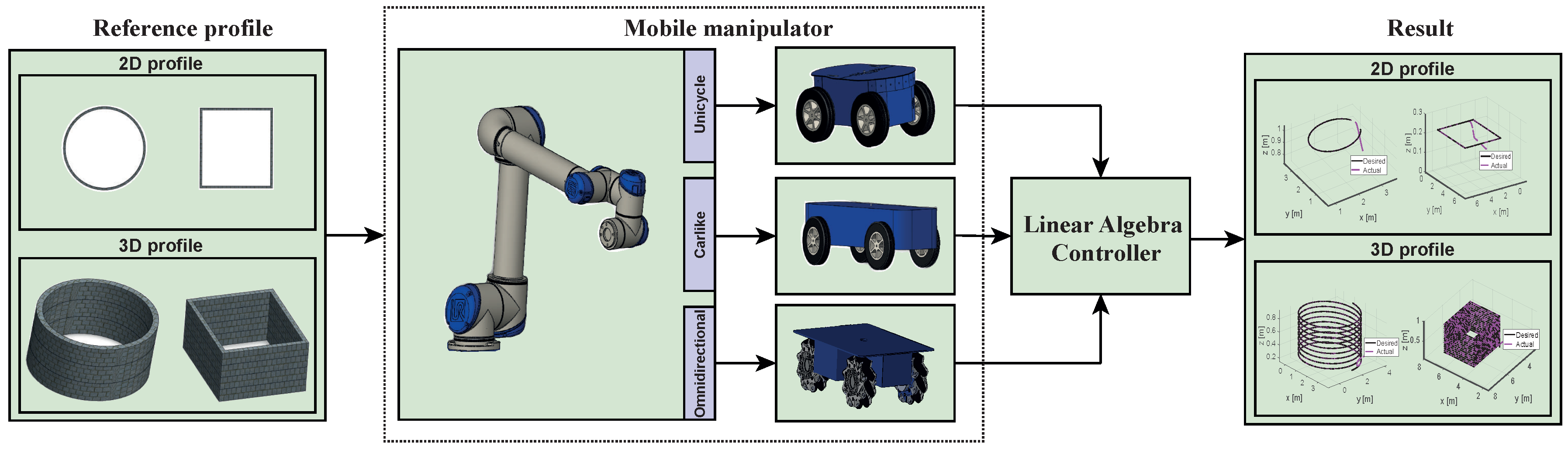
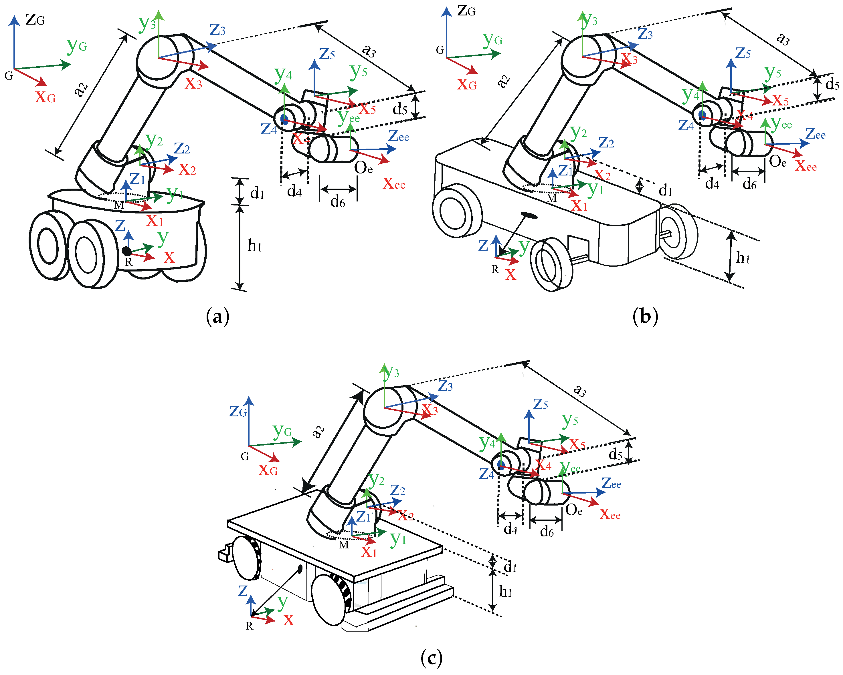
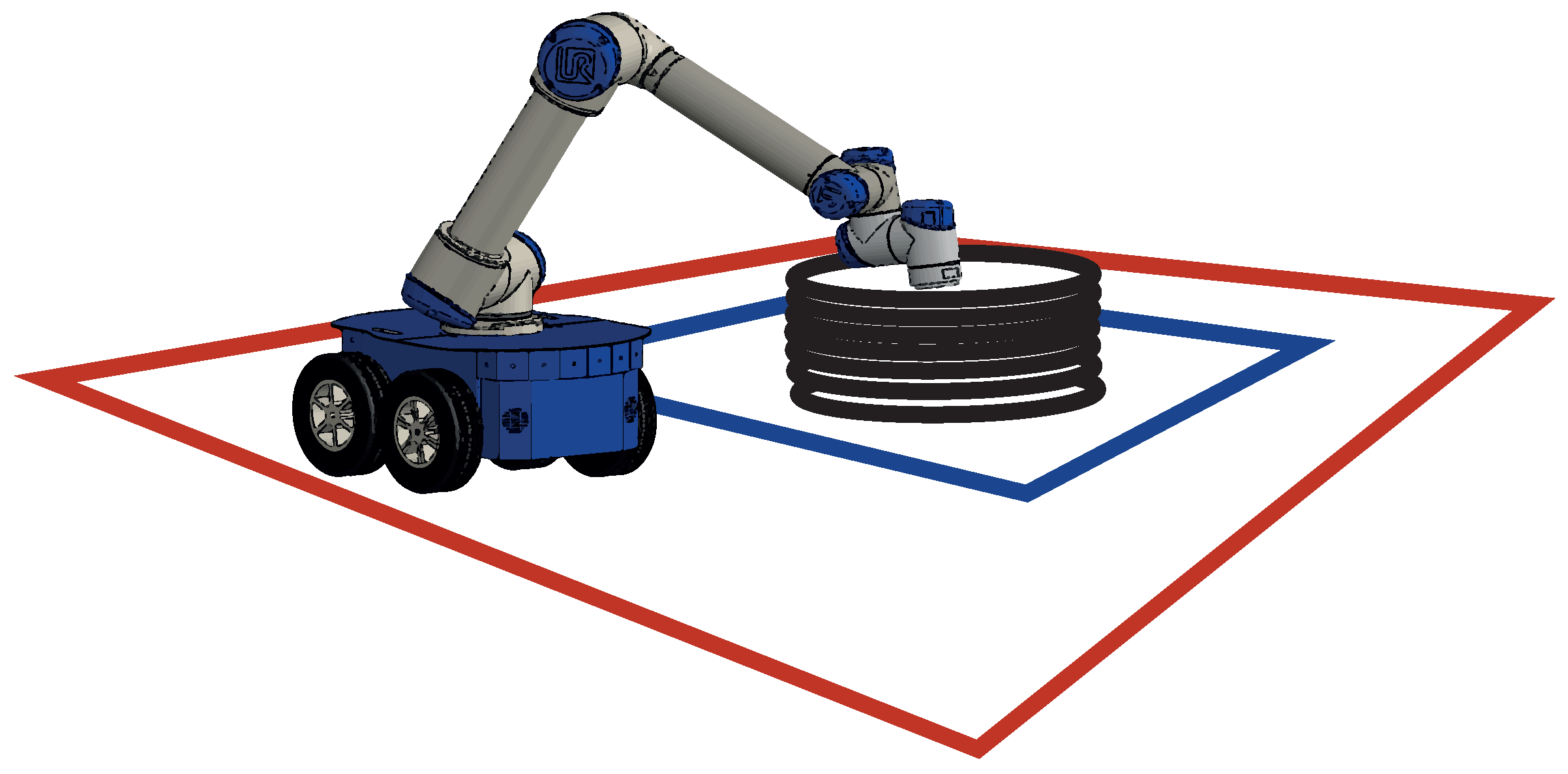
To overcome the later problem, in this work we propose to study the usability of a robotic arm mounted on a mobile platform (also robotic), to cover bigger areas of the construction site and to print convex geometries (for example, the walls of a room). By integrating a mobile platform to the robot manipulator used as 3D printer, we increase its dexterity, its workspace and its capabilities. However, since we use the same robot manipulator, we change the mobile platform to find which one is the most appropriate to be used in the construction site. In particular, we test the following configurations: unicycle, car-like and four wheeled omnidirectional with mecanum wheels [34,35]. We test the performance of the mobile manipulator mounted on the three different platforms in terms of error and effort, when printing several types of building elements. For the remainder of this work, we will refer to the robotic platform as the mobile manipulator.
The selection of proper machine and printing strategy according to the building pieces printed is crucial for a successful efficiency and versatility of this emerging technology for 3D-printed construction with robotic systems. In this context, the efficient use of robotic platforms is related to their operational power consumption [36]. When the robot performs a printing task, the power consumption varies significantly during the operation of the robot, and comprise the actuation systems that will interact with the environment and the construction process.
For example, the use of energy resources of the mobile manipulator depends on the interaction of the platform with the environment and the motion it executes. For this reason, their energy use is governed by the irregularity of the surface of the construction environment, the complexity of the print model, and the payload it supports. In this work, we relate the energy consumption to the cost function in terms of minimum trajectory tracking error with the motion speeds of the mobile manipulator.
As previously stated, this work is focused on studying the usability of mobile manipulator platforms as 3D printing machinery in construction sites, with emphasis in the different existing mobile platforms, in order to provide a novel review and suggest adequate methodologies for buildings construction. Previous work has been done on materials, machines and/or specific printing experiments, but lack of rigorous studies and general approaches about printing procedures with mobile robot platforms. Movement and operation of robots are complex tasks to be combined in a printing process of large pieces, and building execution requires a diversity of elements to be printed in different locations, then to test and define proper strategies is essential to develop the construction with robots. In this context, [8,37] exposes strategies of mobile systems for printing building elements but do not study the toolpath in relation to the machine type and piece design. Such procedure is relevant to develop the printing methodology and define effective approaches and equipments.
This work is organized as follows: Section 2 shows the trajectory profiles in the construction environment, the mathematical derivation of the mobile manipulator model, the strategy followed by the mobile manipulator trajectory tracking controller, and the metrics followed to find mobile platform performance. Section 3 presents the results using the mobile manipulator with the three different mobile platforms previously introduced for different building scenarios. Section 4 shows a discussion about the tasks performed by the mobile manipulator in the construction environments. Finally, the conclusions are shown in Section 5.

2. Materials and Methods

Figure 1 shows the general scheme of the architecture proposed in this work for evaluating the performance of mobile manipulators in the 3D printing case of building elements. To the left, we have two reference profiles: circular and square, in two different views: 2D (two dimensional) and 3D. Such profiles represent the building elements to be printed. When sent to the manipulator, the building elements are converted into path references to be tracked by the end effector (where the extrusor is located) of the manipulator. We consider three mobile platforms where the manipulator is going to be mounted: unicycle type, car-like type (Ackerman) and omnidirectional type (four wheeled with mecanum wheels). The trajectory references are then transformed into motion control commands through a linear algebra controller to ensure that the system mobile manipulator behaves as expected: its end effector—to which the nozzle is attached—moves describing the building element to be printed. In the following subsections, each part of Figure 1 is explained in detail.

2.1. Robot Manipulator

The robotic arm used to perform 3D printing of the building elements is the UR5, manufactured by Universal Robots. This manipulator has six degrees of freedom and a control unit that provides basic joints control as well as a companion computer-computational system in charge of data processing and broadcasting. It supports a payload of 5 kg; its maximum speed is π rad/s and its repeatability is ±0.1 mm. Table 1 shows the main features of this manipulator.
One of the main advantages of this robot is that it offers low-level programing with high cycle time. The robot can be modelled using Denavit-Hartenberg parameters or geometrical model and it has been used in novel applications in different industries [38]. Although we used the UR5 robotic arm in this work, the procedure followed and presented herein can be extended to other manipulators.

2.2. Mobile Robot

Table 2 shows the kinematic models in continuous and discrete-time of the non-holonomic (i.e., unicycle and carlike) and holonomic (i.e., omnidirectional robot) platforms studied in this work. We chose such three mobile platforms since they are the most used ones as reported in the literature [39,40,41]. However, as also stated for the UR5 case, if needed, the procedure presented in this work can be adapted to other types of platforms.
As it is shown in Table 2, the three robots have three degrees of freedom, named as x , y and ψ , which apply to rotation and translation of the robot in the plane, considering only planar terrains. In the case of the unicycle robot, it can turn around its control point [42]; however, the car-like model has to follow a circle based path [43], making it impossible to turn without displacing [44]. On the other hand, the omnidirectional vehicle can displace at any direction in the plane. More information regarding the kinematic (and dynamic) constraints of each robotic type can be found in [45,46,47].
In Table 2, μ and ω are the linear and angular velocities of the unicycle and car-like robot; a is the distance between the centre of the platform and the centre of mass in global coordinates; δ is the heading of the car-like; L is the length between axles of the car-like robot and ( l + d ) is the distance from the centre of the wheel to the centre of mass of the omnidirectional robot; v 1 , v 2 , v 3 , v 4 are wheel velocities of the omnidirectional robot. Furthermore, γ is defined by cos ψ sin ψ and β is defined by sin ψ + cos ψ . Suffix n represents sampling time.

2.3. Mobile Manipulator

As stated in Section 1, when the robot manipulator is attached to one of the mobile platforms mentioned in Section 2.2, the combined system becomes a mobile manipulator. Its kinematic is the result of also combining the manipulator kinematics with the mobile robot kinematics. Hence, we use the Denavit-Hartenverg convention to derive the mobile manipulator kinematic model, following the guidelines previously published by [38].
Table 3 shows the kinematic model of the robotic arm mounted on the three different mobile platforms. For unicycle and car-like configurations, linear and angular velocity defines the motion of the mobile platform. The orientation of the unicycle robot is defined by angular rotation. However, in the car-like configuration, the rotation is a function of the linear velocity and the length of the mobile platform. For the omnidirectional robot, rotation and linear velocity are a function of the angular velocity described by the wheels.
where,
J = h e e f x , y , ψ , θ 1 , , θ 5
and h e e = [ x e e y e e z e e ] T is the position of the end-effector –with respect to some global reference frame–, and [ θ 1 θ 2 θ 3 θ 4 θ 5 ] T are its joint angles. Furthermore, [ x ˙ e e y ˙ e e z ˙ e e ] T is the velocity of the end-effector; θ ˙ 1 , θ ˙ 2 , θ ˙ 3 , θ ˙ 4 and θ ˙ 5 are angular velocities of the joints. Figure 2 shows the manipulator mounted on three mobile platforms (unicycle, car-like and omnidirectional with four mecanum wheels). Angles and velocities are represented according to a global reference frame G, R is the local coordinate of the mobile robot, M represents the local coordinate of the manipulator UR5 and the coordinate of the end-effector is O e . The manipulator links are represented by d 1 , a 2 , a 3 , d 4 , and d 5 , and the height of the mobile platform is h 1 .

Workspace Restriction

Since this work is focused on analysing the usability of mobile manipulators in construction environments, it becomes necessary to also analyse the workspace surrounding the platform due to the fact that its motion is constrained by the environment layout, the terrain and the task restrictions, the later with the aim of guaranteeing the effectiveness and safety of the operation.
In our work, the first constraint impossed to the system is the restriction of the workspace, by two times the maximum extension of the robot manipulator. Thus, it limits the displacement of the platform by allowing it no more than one time the robot manipulator extension, to ensure the safety of the operation. Other criteria might apply since it is to be noted that the platform does not move freely in a construction site. In the end, the idea is to consider the design requirements and shapes of the building elements to evaluate the most appropriate workspace, to thus avoid excuting tasks at the maximum point of operation, or to invade an area beyond the printed building element [19]. Figure 3 summarizes the restrictions considered in this work for all the building elements studied, where the solid red line represents the outer limit imposed on the mobile platform, this limit may not exceed twice the maximum length of the robotic arm; the solid blue line is the inner limit and cannot exceed the maximum arm length.

2.4. Building Elements

The construction industry uses complex building element profiles to build houses and buildings. These surfaces result in high profile projects or iconic architecture designs. The main challenges of building element profiles are their complex geometries, size and repeatability of the task, which can affect the performance of the robotic systems [48,49]. Therefore the need of using mobile manipulators.
We generate four trajectory profiles following the guidelines presented in [26]. Such profiles are then converted into reference trajectories fed to the mobile manipulator, parametrized in time and discretized with sampling time of 0.1 s (however, other sampling criterion might apply). The building elements studied in this work are: circle, helical, mesh and square; which are also depicted in Figure 4.
We tested three different sizes of the above building element: small (length = 1 m, width = 1 m, height = 1.2 m); medium (length = 2 m, width = 2 m, height = 1.2 m); and large (length = 5 m, width = 5 m, height = 1.2 m), following the guidelines presented in [50,51]. Such building elements are uniform, except for the corners in square building elements, where the change is abrupt and might affect the orientation of the mobile platform. For the circle and helical case, the diameter proposed was of 1 m (small size), 2 m (medium size) and 4 m (large size).
The generation of the building elements is divided into 2D layers to generate 3D model geometries. Each building element is represented by circular and square geometries. Additionally, for printing purposes, we added the following constraints: printing speed between 0.01 and 1 ms 1 [52]; maximum mobile platform speed of 0.7 ms 1 ; and we limited the maximum angles of the joints to 2 π to 2 π rad [53].

2.5. Motion Control

In this work, we propose a trajectory tracking algorithm for the mobile manipulator to ensure 3D printing of building elements at constant speed. To this end, a trajectory tracking algorithm is implemented using the controller proposed by Scaglia et al. [54]. This controller guarantees velocity regulation between the end effector and the printing task.
The kinematic model presented in Table 3 can be expressed as follows:
h ˙ t = f Γ , θ 1 ˙ , θ 2 ˙ , θ 3 ˙ , θ 4 ˙ , θ 5 ˙
The control variables of the mobile platform are represented by Γ . We then defined Γ for each mobile platform and replaced it in Equation (2), where Γ = μ , ω represents the control variables of the unicycle robot, Γ = μ , μ L is defined for a car-like robot and Γ = v 1 , v 2 , v 3 , v 4 represents the control signals of the omnidirectional robot.
The continuous system shown in Equation (2) can be rewritten discretized using an Euler approach as shown below, for the three models:
h n + 1 = h n + n T o n + 1 T o f Γ , θ ˙ 1 , θ 2 ˙ , θ 3 ˙ , θ 4 ˙ , θ 5 ˙ d t
h n + 1 h n + T 0 f Γ n , θ 1 n , θ 2 n , θ 3 n , θ 4 n , θ 5 n
f Γ n , θ 1 n , θ 2 n , θ 3 n , θ 4 n , θ 5 n = J n Γ n θ 1 n θ 2 n θ 3 n θ 4 n θ 5 n
where J n is the discrete Jacobian matrix of J from Table 3 at each sampling time. The values of h t at discrete time t = n T o , where T o is the sampling period, and n 0 , 1 , 2 , , are denoted as h n = x e e n , y e e n , z e e n T and h n + 1 = x e e n + 1 , y e e n + 1 , z e e n + 1 T . The kinematic model of the mobile manipulator, is defined by:
x e e n + 1 x e e n T o y e e n + 1 y e e n T o z e e n + 1 z e e n T o = J n U n
where U n = Γ n θ 1 n θ 2 n θ 3 n θ 4 n θ 5 n T . The proposed control law is defined by:
U c n = J n + x e e d n + 1 k x x e e d n x e e n x e e n y e e d n + 1 k y y e e d n y e e n y e e n z e e d n + 1 k z z e e d n z e e n z e e n ,
where J n + is the Jacobian pseudo-inverse matrix of the mobile manipulator, the position of the end-effector is defined by [ x e e ( n ) y e e ( n ) z e e ( n ) ] T framed in a global reference system, and K = [ k x k y k z ) ] T is the set of tuning parameters. The desired path of the end-effector is given by [ x e e d ( n ) y e e d ( n ) z e e d ( n ) ] T . Furthermore, U c n represents the linear and angular velocities necessary to make the mobile manipulator move from the current state n to the desired one at n + 1 , where n represents time instant.
Assuming perfect speed tracking, it has U n U c n and replacing Equation (7) in Equation (6), it is obtained:
x e e n + 1 x e e n y e e n + 1 y e e n z e e n + 1 z e e n = x e e d n + 1 k x x e e d n x e e n x e e n y e e d n + 1 k y y e e d n y e e n y e e n z e e d n + 1 k z z e e d n z e e n z e e n
In Equation (7), k x , k y and k z are tuning parameters (see [55] for further reading on how to tune such parameters).

2.6. Evaluation Metrics

To quantify the mobile manipulator performance, we used the cost function defined by the actuators effort to reach the reference trajectory [55] and the integral absolute error index (IAE) between the trajectory of the mobile manipulator and the desired trajectory [56]. In particular, we use the cumulative control effort and cumulative error defined by:
C μ , ω , θ i ˙ Ω = 1 2 t = 0 # Ω μ 2 + ω 2 + λ θ ˙ 1 2 + θ ˙ 2 2 + θ ˙ 3 2 + θ ˙ 4 2 + θ ˙ 5 2
C x , y , z Ω = 1 2 t = 0 # Ω | x r e f x e e | d t 2 + | y r e f y e e | d t 2 + | z r e f z e e | d t 2 2
where, Equations (9) and (10) show the cumulative controller effort and cumulative integral absolute error-index respectively; Ω is the desired trajectory given to the controller, # Ω the number of desired points.
Finally, the cumulative total cost can be defined as the sum of the cumulative control effort and cumulative integral absolute error-index, as shown in Equation (11):
C T o t Ω = C x , y , z Ω + α C μ , ω , θ ˙ 1 5 Ω
where λ (in Equation (9)) and α (in Equation (11)) are coefficients that allow the sum of terms from different dimensions. It is to be noted that both the control effort and the IAE index, can be considered as metrics of the effectiveness of the robotic process. We do not evaluate the quality of printing task per se, nor of its material.
The cumulative controller effort and cumulative integral absolute error-index are normalized in the range 0 , 1 , since the total cost is a non-dimensional value.

3. Results

To implement the trajectory tracking controller shown in Section 2.5, we first set the tuning parameters presented in Equation (7), presented in Table 4 below.
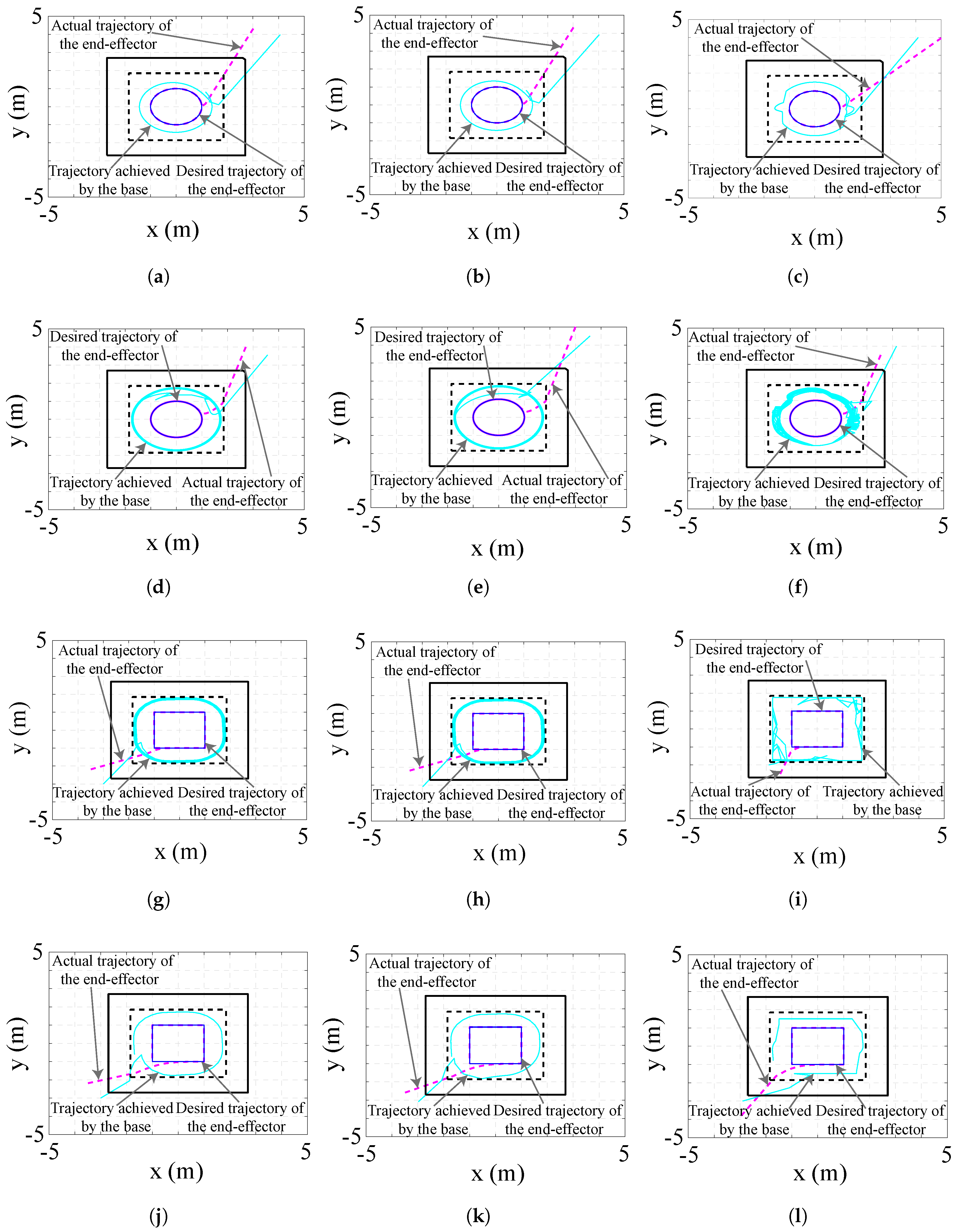
Figure 5 shows the computational analysis obtained in the experiments for the three mobile manipulators with the four trajectory profiles. The first column corresponds to the unicycle robot, the second and third column correspond to the car-like and omnidirectional robot, respectively. The reference trajectory of the end-effector is described by the solid blue line whereas the dashed magenta line corresponds to the actual tracked trajectory. In addition, we have included the trajectory of the mobile platform in the solid cyan line. The solid black line represents the outer limit imposed on the mobile platform, whereas the dashed black line, the inner limit.
The experiments in Figure 5 consisted of printing four medium-sized building elements (length = 2 m, width = 2 m). It is possible to observe that the tracked trajectory profile –dashed magenta line– converges to the reference path –solid cyan line– for each studied platform. The performance comparison of the mobile platforms as they are printing the building elements is shown in Figure 5a–c, corresponding to the unicycle, car-like and omnidirectional platforms, respectively. It is worth noting that the mobile robot trajectory is independent of the end-effector trajectory.
The second experiment consisted of printing a medium-size helical building element (length = 2 m, width = 2 m, height = 0.92 m), and are shown in Figure 5d–f. This profile is formed by 50 circular layers and the distance between layers is 0.01 m. The solid cyan line shows the displacement of the unicycle and car-like robot, as shown in Figure 5d,e. These two platforms have a circular motion that increases as printing progresses, without exceeding the proposed inner limit of the workspace. The omnidirectional platform follows a circular trajectory with a sinusoidal movement, as can be seen in Figure 5f.
The third experiment consists of printing a mesh profile, as shown in Figure 5g–i. The profile is of medium size (length = 2 m, width = 2 m, height = 0.55 m) and is formed by 50 square layers; the distance between layers is 0.01m. The displacement of the mobile platform is described by a solid cyan line. Figure 5g,h show the trajectory described by the unicycle and car-like robot, respectively. Both mobile robots have a nearly square trajectory with curves in the corners, in contrast to the omnidirectional robot that describes a square trajectory with sharp turns at the corners, as shown in Figure 5i.
The performance comparison between mobile platforms for a medium-size square profile of length = 2 m, width = 2 m, height = 0.26 m is shown in Figure 5j–l. The solid cyan line describes of displacement of the mobile platforms. Figure 5j,k show that the unicycle and car-like robot performs a quasi-circular trajectory. Both mobile robots have a transient before the desired trajectory is achieved. On the other hand, the omnidirectional robot describes a quasi-square trajectory without a transient, this result can be seen in Figure 5l.
The results obtained from the printing of building elements –circular and helical– of different sizes are summarized in Table 5. The statistical analysis was performed based on the cost function defined in Section 2.6. It can be seen that the omnidirectional robot has the lowest cost function.
For the square and mesh profiles, the platform performance is shown in Table 6. For small and large sizes of square profiles, the platform with the lowest costs is the omnidirectional robot. For the medium square profile, the car-like platform presents the lowest cost. The omnidirectional robot has the lowest cost function for all sizes of the mesh profile.

4. Discussion

In this work, we proposed a performance comparison of a robotic arm mounted on three different widely used mobile platforms. Table 7 summarises the capabilities and skills of the different mobile platforms considered in this work, showing their pros and cons in the problem faced herein. The analysis of results shows that the omnidirectional robot is the best option for 3D printing of building elements used in the construction industry. In terms of the cost function, the omnidirectional robot has the lowest cost function for the mesh and square trajectory. For circular and helical trajectory, the best platform is the omnidirectional robot.
The car-like robot has a high sensitivity to the initial state error of the robot, which produces an error at the beginning of the printing that is then corrected. However, the unicycle robot has a lower initial state error. The initial state of the robot varies with the trajectory (see [55] for further details).
Controlling the height between layers is an important parameter during printing to avoid deviation in either direction that influences the quality, geometry, and appearance of the final printed product. In this work, we considered a height between layers of 0.01 m, which is the minimum distance of printing in the construction process [57] and a vertical displacement of 0.50 m for our experiments.
A crucial factor in 3D printing is the velocity of operation of the robotic system. Our work tries to address this challenge, which is a function of the printing material. For all the tests carried out, we set the velocity to a maximum of 0.01 ms 1 . However, the velocity might vary depending on the trajectory shape, size and the complexity of the geometry profile. A pre-analysis of the effect of speed on the different trajectory profiles is an advantage in the area of construction to improve the performance of 3D printing.
The workspace is another important item to consider. In the experiments carried out, a square-shaped workspace is proposed, that establish the limits of operation of the mobile manipulator, considering that the end-effector does not invade the printing area. Under real site conditions, the system should be modified to avoid obstacles (e.g., people and construction tools).
This work proposes a kinematic model of the mobile manipulator, whose analysis is based on the application of 3D printing for the construction industry. This analysis does not consider the dynamic model of the system and the forces involved in 3D printing. Furthermore, a future analysis may be to study the effects of putting a nozzle on the end-effector, where variables such as weight, size and diameter of the nozzle are considered.

5. Conclusions

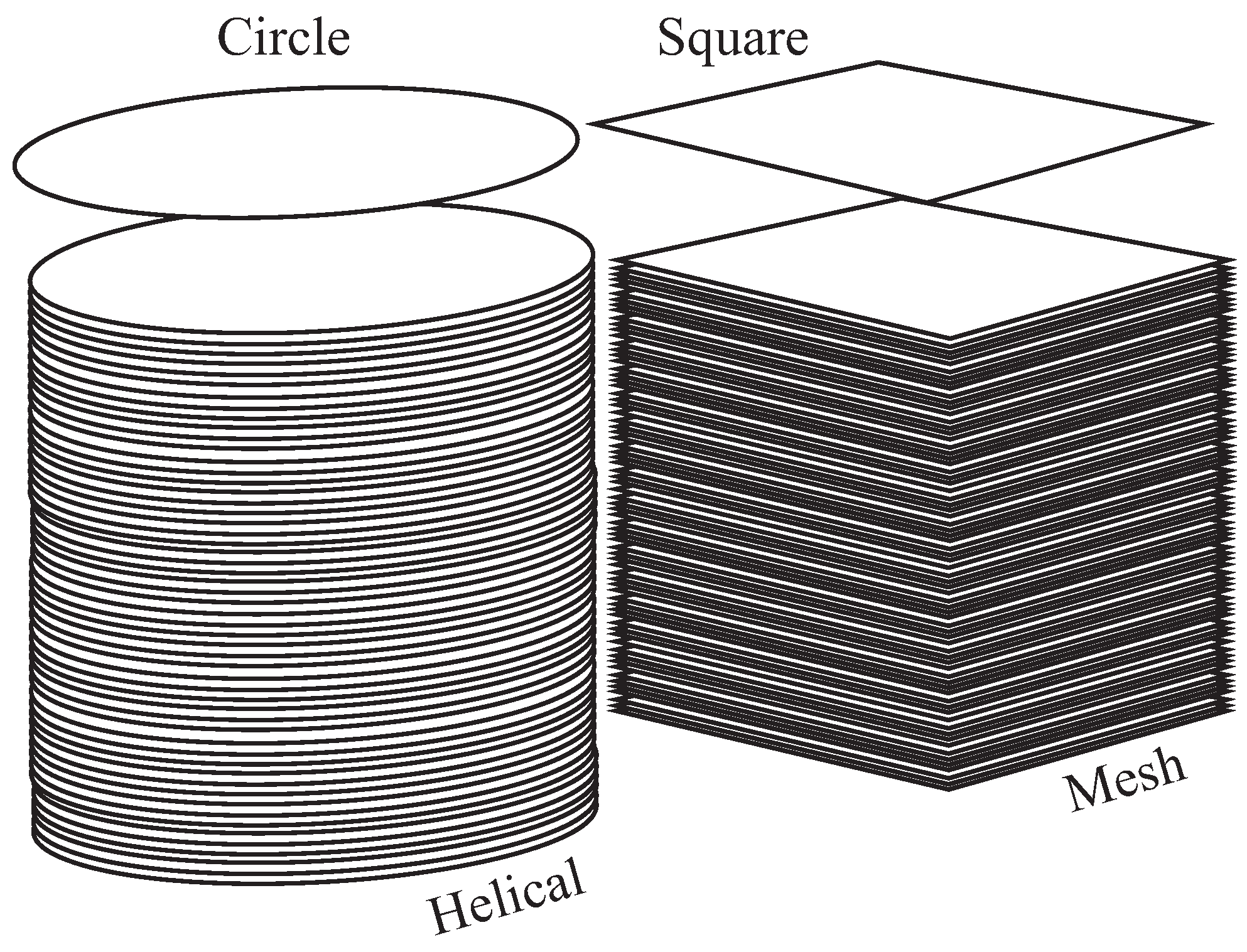
An experimental comparison of a robotic arm mounted on three mobile platforms in 3D printing applications was presented. The evaluation of the printing performance was based in two well known metrics used in robotics: the cumulative control effort and cumulative integral absolute error index. As a case study, we proposed four profiles (circular, helical, mesh and square), which are representative of the geometry of building elements usually printed using robotic technology. Three mobile platforms were used: unicycle like, car-like and omnidirectional with four mecanum wheels; combined with a robotic arm UR5. The experiments have shown that the printing error converges to zero for all three proposed trajectories and that the car-like showed the lowest cost for squared and mesh building elements. On the other hand, the car-like and unicycle showed the lowest cost for the circle and helical profile. The omnidirectional showed promising results, but the nature of its wheels makes the platform difficult to use in non-flat terrains, as it is in construction sites.
On the other hand, the greater effectiveness demonstrated by the mobile platforms studied to print circular and helical building elements is probably driving a preference for these architectural forms in the first printed constructions carried out. That suggests buildings with curved and sinuous walls that can have new spatial expressions.
Future developments will be focused on studying and modelling the dynamics of the system. As the performance of cooperative installations for the impression of constructive elements. As well as the effectiveness of different architectural forms.

Author Contributions

Conceptualization: All authors; The research was performed under the supervision of F.A.C. Literature Review: R.G.R., F.A.C., R.G.A. and A.M.-R. Research Method: R.G.R. and F.A.C.; Software: R.G.R. Drafting the article based on the results: R.G.R. and F.A.C. Reviewed the paper R.G.A. and A.M.-R. All authors have read and agreed to the published version of the manuscript.

Funding

This research was funded by ANID (ex CONICYT) FONDECYT 1181015 and the Advanced Center of Electrical and Electronic Engineering AC3E CONICYT FB008, DGIIP-UTFSM Chile.

Acknowledgments

The authors would like to the AC3E-UTFSM.

Conflicts of Interest

The authors declare no conflict of interest.

References

  1. Gramazio, F.; Kohler, M. Made by Robots: Challenging Architecture at a Larger Scale; John Wiley & Sons: London, UK, 2014. [Google Scholar]
  2. Tay, Y.W.D.; Panda, B.; Paul, S.C.; Noor Mohamed, N.A.; Tan, M.J.; Leong, K.F. 3D printing trends in building and construction industry: A review. Virtual Phys. Prototyp. 2017, 12, 261–276. [Google Scholar] [CrossRef]
  3. Bock, T. The future of construction automation: Technological disruption and the upcoming ubiquity of robotics. Autom. Constr. 2015, 59, 113–121. [Google Scholar] [CrossRef]
  4. Valente, M.; Sibai, A.; Sambucci, M. Extrusion-Based Additive Manufacturing of Concrete Products: Revolutionizing and Remodeling the Construction Industry. J. Compos. Sci. 2019, 3, 88. [Google Scholar] [CrossRef] [Green Version]
  5. Li, S.; Liu, L.; Peng, C. A Review of Performance-Oriented Architectural Design and Optimization in the Context of Sustainability: Dividends and Challenges. Sustainability 2020, 12, 1427. [Google Scholar] [CrossRef] [Green Version]
  6. Gibson, I.; Rosen, D.W.; Stucker, B. Additive Manufacturing Technologies; Springer: New York, NY, USA, 2014; Volume 17. [Google Scholar]
  7. Paul, S.C.; Tay, Y.W.D.; Panda, B.; Tan, M.J. Fresh and hardened properties of 3D printable cementitious materials for building and construction. Arch. Civ. Mech. Eng. 2018, 18, 311–319. [Google Scholar] [CrossRef]
  8. Dritsas, S.; Soh, G.S. Building robotics design for construction. Constr. Robot. 2019, 3, 1–10. [Google Scholar] [CrossRef]
  9. Tibaut, A.; Rebolj, D.; Perc, M.N. Interoperability requirements for automated manufacturing systems in construction. J. Intell. Manuf. 2016, 27, 251–262. [Google Scholar] [CrossRef]
  10. Khoshnevis, B.; Hwang, D.; Yao, K.T.; Yeh, Z. Mega-scale fabrication by contour crafting. Int. J. Ind. Syst. Eng. 2006, 1, 301–320. [Google Scholar] [CrossRef] [Green Version]
  11. Lim, S.; Le, T.; Webster, J.; Buswell, R.; Austin, A.; Gibb, A.; Thorpe, T. Fabricating construction components using layered manufacturing technology. In Proceedings of the Global Innovation in Construction Conference, Loughborough, UK, 13–16 September 2009; pp. 512–520. [Google Scholar]
  12. Cesaretti, G.; Dini, E.; De Kestelier, X.; Colla, V.; Pambaguian, L. Building components for an outpost on the Lunar soil by means of a novel 3D printing technology. Acta Astronaut. 2014, 93, 430–450. [Google Scholar] [CrossRef]
  13. Mueller, R.P.; Howe, S.; Kochmann, D.; Ali, H.; Andersen, C.; Burgoyne, H.; Chambers, W.; Clinton, R.; De Kestellier, X.; Ebelt, K.; et al. Automated additive construction (AAC) for Earth and space using in-situ resources. In Proceedings of the Fifteenth Biennial ASCE Aerospace Division International Conference on Engineering, Science, Construction, and Operations in Challenging Environments (Earth & Space 2016), Orlando, FL, USA, 11–15 April 2016; American Society of Civil Engineers: Reston, VA, USA, 2016. [Google Scholar]
  14. Zareiyan, B.; Khoshnevis, B. Interlayer adhesion and strength of structures in Contour Crafting-Effects of aggregate size, extrusion rate, and layer thickness. Autom. Constr. 2017, 81, 112–121. [Google Scholar] [CrossRef]
  15. Marchment, T.; Sanjayan, J. Mesh reinforcing method for 3D Concrete Printing. Autom. Constr. 2020, 109, 102992. [Google Scholar] [CrossRef]
  16. Gosselin, C.; Duballet, R.; Roux, P.; Gaudillière, N.; Dirrenberger, J.; Morel, P. Large-scale 3D printing of ultra-high performance concrete–a new processing route for architects and builders. Mater. Des. 2016, 100, 102–109. [Google Scholar] [CrossRef] [Green Version]
  17. Bong, S.H.; Nematollahi, B.; Nazari, A.; Xia, M.; Sanjayan, J. Method of Optimisation for Ambient Temperature Cured Sustainable Geopolymers for 3D Printing Construction Applications. Materials 2019, 12, 902. [Google Scholar] [CrossRef] [PubMed] [Green Version]
  18. Paolini, A.; Kollmannsberger, S.; Rank, E. Additive manufacturing in construction: A review on processes, applications, and digital planning methods. Addit. Manuf. 2019, 30, 100894. [Google Scholar] [CrossRef]
  19. Furet, B.; Poullain, P.; Garnier, S. 3D printing for construction based on a complex wall of polymer-foam and concrete. Addit. Manuf. 2019, 28, 58–64. [Google Scholar] [CrossRef]
  20. Li, V.C.; Bos, F.P.; Yu, K.; McGee, W.; Ng, T.Y.; Figueiredo, S.C.; Nefs, K.; Mechtcherine, V.; Nerella, V.N.; Pan, J.; et al. On the emergence of 3D printable Engineered, Strain Hardening Cementitious Composites (ECC/SHCC). Cem. Concr. Res. 2020, 132, 106038. [Google Scholar] [CrossRef]
  21. Dharmawan, A.G.; Sedore, B.W.C.; Foong, S.; Soh, G.S. An agile robotic system mounted on scaffold structures for on-site construction work. Constr. Robot. 2017, 1, 15–27. [Google Scholar] [CrossRef] [Green Version]
  22. Bard, J.; Cupkova, D.; Washburn, N.; Zeglin, G. Robotic concrete surface finishing: A moldless approach to creating thermally tuned surface geometry for architectural building components using Profile-3D-Printing. Constr. Robot. 2018, 2, 53–65. [Google Scholar] [CrossRef]
  23. Dörfler, K.; Hack, N.; Sandy, T.; Giftthaler, M.; Lussi, M.; Walzer, A.N.; Buchli, J.; Gramazio, F.; Kohler, M. Mobile robotic fabrication beyond factory conditions: Case study Mesh Mould wall of the DFAB HOUSE. Constr. Robot. 2019, 3, 53–67. [Google Scholar] [CrossRef] [Green Version]
  24. Reinhardt, D.; Titchkosky, N.; Bickerton, C.; Watt, R.; Wozniak-O’Connor, D.; Candido, C.; Cabrera, D.; Page, M.; Bohnenberger, S. Towards onsite, modular robotic carbon-fibre winding for an integrated ceiling structure. Constr. Robot. 2019, 3, 23–40. [Google Scholar] [CrossRef] [Green Version]
  25. Bos, F.; Wolfs, R.; Ahmed, Z.; Salet, T. Additive manufacturing of concrete in construction: Potentials and challenges of 3D concrete printing. Virtual Phys. Prototyp. 2016, 11, 209–225. [Google Scholar] [CrossRef] [Green Version]
  26. Davtalab, O.; Kazemian, A.; Khoshnevis, B. Perspectives on a BIM-integrated software platform for robotic construction through Contour Crafting. Autom. Constr. 2018, 89, 13–23. [Google Scholar] [CrossRef]
  27. Mechtcherine, V.; Nerella, V.N.; Will, F.; Näther, M.; Otto, J.; Krause, M. Large-scale digital concrete construction–CONPrint3D concept for on-site, monolithic 3D-printing. Autom. Constr. 2019, 107, 102933. [Google Scholar] [CrossRef]
  28. Perrot, A.; Amziane, S. 3D Printing in Concrete: General Considerations and Technologies. 3D Print. Concr State Art Chall. Digit. Constr. Revolut. 2019, 1–40. [Google Scholar] [CrossRef]
  29. Kasperzyk, C.; Kim, M.K.; Brilakis, I. Automated re-prefabrication system for buildings using robotics. Autom. Constr. 2017, 83, 184–195. [Google Scholar] [CrossRef] [Green Version]
  30. Perrot, A.; Rangeard, D.; Pierre, A. Structural built-up of cement-based materials used for 3D-printing extrusion techniques. Mater. Struct. 2016, 49, 1213–1220. [Google Scholar] [CrossRef]
  31. de Soto, B.G.; Agustí-Juan, I.; Hunhevicz, J.; Joss, S.; Graser, K.; Habert, G.; Adey, B.T. Productivity of digital fabrication in construction: Cost and time analysis of a robotically built wall. Autom. Constr. 2018, 92, 297–311. [Google Scholar] [CrossRef]
  32. Ngo, T.D.; Kashani, A.; Imbalzano, G.; Nguyen, K.T.; Hui, D. Additive manufacturing (3D printing): A review of materials, methods, applications and challenges. Compos. Part B Eng. 2018, 143, 172–196. [Google Scholar] [CrossRef]
  33. Buchanan, C.; Gardner, L. Metal 3D printing in construction: A review of methods, research, applications, opportunities and challenges. Eng. Struct. 2019, 180, 332–348. [Google Scholar] [CrossRef]
  34. Wang, C.; Liu, X.; Yang, X.; Hu, F.; Jiang, A.; Yang, C. Trajectory tracking of an omni-directional wheeled mobile robot using a model predictive control strategy. Appl. Sci. 2018, 8, 231. [Google Scholar] [CrossRef] [Green Version]
  35. Pappalardo, C.M.; Guida, D. Forward and Inverse Dynamics of a Unicycle-Like Mobile Robot. Machines 2019, 7, 5. [Google Scholar] [CrossRef] [Green Version]
  36. Martínez-Rocamora, A.; García-Alvarado, R.; Casanova-Medina, E.; González-Böhme, L.F.; Auat-Cheein, F. Parametric Programming of 3D Printed Curved Walls for Cost-Efficient Building Design. J. Constr. Eng. Manag. 2020, 146, 04020039. [Google Scholar] [CrossRef]
  37. Giftthaler, M.; Sandy, T.; Dörfler, K.; Brooks, I.; Buckingham, M.; Rey, G.; Kohler, M.; Gramazio, F.; Buchli, J. Mobile robotic fabrication at 1: 1 scale: The in situ fabricator. Constr. Robot. 2017, 1, 3–14. [Google Scholar] [CrossRef] [Green Version]
  38. Kebria, P.M.; Al-Wais, S.; Abdi, H.; Nahavandi, S. Kinematic and dynamic modelling of UR5 manipulator. In Proceedings of the 2016 IEEE International Conference on Systems, Man, and Cybernetics (SMC), Budapest, Hungary, 9–12 October 2016; pp. 4229–4234. [Google Scholar]
  39. Vallejo-Alarcón, M.; Castro-Linares, R.; Velasco-Villa, M. Unicycle-type robot & quadrotor leader-follower formation backstepping control. IFAC-PapersOnLine 2015, 48, 51–56. [Google Scholar]
  40. Moreno, J.; Clotet, E.; Lupiañez, R.; Tresanchez, M.; Martínez, D.; Pallejà, T.; Casanovas, J.; Palacín, J. Design, implementation and validation of the three-wheel holonomic motion system of the assistant personal robot (APR). Sensors 2016, 16, 1658. [Google Scholar] [CrossRef] [PubMed] [Green Version]
  41. Li, X.; Zell, A. Motion control of an omnidirectional mobile robot. In Informatics in Control, Automation and Robotics; Springer: Berlin/Heidelberg, Germany, 2009; pp. 181–193. [Google Scholar]
  42. Kamel, M.A.; Zhang, Y. Decentralized leader-follower formation control with obstacle avoidance of multiple unicycle mobile robots. In Proceedings of the 2015 IEEE 28th Canadian Conference on Electrical and Computer Engineering (CCECE), Halifax, NS, Canada, 3–6 May 2015; pp. 406–411. [Google Scholar]
  43. Song, Z.; Ren, H.; Zhang, J.; Ge, S.S. Kinematic analysis and motion control of wheeled mobile robots in cylindrical workspaces. IEEE Trans. Autom. Sci. Eng. 2015, 13, 1207–1214. [Google Scholar] [CrossRef]
  44. Raj, J.; Raghuwaiya, K.; Vanualailai, J.; Sharma, B. Navigation of Car-Like Robots in Three-Dimensional Space. In Proceedings of the 2018 5th Asia-Pacific World Congress on Computer Science and Engineering (APWC on CSE), Nadi, Fiji, 10–12 December 2018; pp. 271–275. [Google Scholar]
  45. Patle, B.; Pandey, A.; Parhi, D.; Jagadeesh, A. A review: On path planning strategies for navigation of mobile robot. Def. Technol. 2019, 15, 582–606. [Google Scholar] [CrossRef]
  46. Rathinam, S.; Manyam, S.G.; Zhang, Y. Near-Optimal Path Planning for a Car-Like Robot Visiting a Set of Waypoints With Field of View Constraints. IEEE Robot. Autom. Lett. 2019, 4, 391–398. [Google Scholar] [CrossRef]
  47. Sun, Z.; Dai, L.; Liu, K.; Xia, Y.; Johansson, K.H. Robust MPC for tracking constrained unicycle robots with additive disturbances. Automatica 2018, 90, 172–184. [Google Scholar] [CrossRef]
  48. Tahmasebinia, F.; Niemelä, M.; Ebrahimzadeh Sepasgozar, S.; Lai, T.; Su, W.; Reddy, K.; Shirowzhan, S.; Sepasgozar, S.; Marroquin, F. Three-Dimensional Printing Using Recycled High-Density Polyethylene: Technological Challenges and Future Directions for Construction. Buildings 2018, 8, 165. [Google Scholar] [CrossRef] [Green Version]
  49. Tomé, A.; Vizotto, I.; Valença, J.; Júlio, E. Innovative Method for Automatic Shape Generation and 3D Printing of Reduced-Scale Models of Ultra-Thin Concrete Shells. Infrastructures 2018, 3, 5. [Google Scholar] [CrossRef] [Green Version]
  50. Bogue, R. 3D printing: The dawn of a new era in manufacturing? Assem. Autom. 2013, 33, 307–311. [Google Scholar] [CrossRef]
  51. Kietzmann, J.; Pitt, L.; Berthon, P. Disruptions, decisions, and destinations: Enter the age of 3-D printing and additive manufacturing. Bus. Horiz. 2015, 58, 209–215. [Google Scholar] [CrossRef]
  52. Izard, J.B.; Dubor, A.; Hervé, P.E.; Cabay, E.; Culla, D.; Rodriguez, M.; Barrado, M. Large-scale 3D printing with cable-driven parallel robots. Constr. Robot. 2017, 1, 69–76. [Google Scholar] [CrossRef]
  53. Universal Robots. 2020. Available online: https://www.universal-robots.com/es/ (accessed on 20 April 2020).
  54. Scaglia, G.; Montoya, L.Q.; Mut, V.; di Sciascio, F. Numerical methods based controller design for mobile robots. Robotica 2009, 27, 269–279. [Google Scholar] [CrossRef] [Green Version]
  55. Scaglia, G.; Serrano, E.; Rosales, A.; Albertos, P. Linear interpolation based controller design for trajectory tracking under uncertainties: Application to mobile robots. Control Eng. Pract. 2015, 45, 123–132. [Google Scholar] [CrossRef]
  56. Deepyaman, M.; Ayan, A.; Mithun, C.; Amit, K.; Ramdoss, J. Tuning PID and PIλ Dμ controllers using the integral time absolute error criteria. In Proceedings of the 4th International Conference on Information and Automation for Sustainability ICIAFS, Colombo, Sri Lanka, 12–14 December 2008; pp. 457–462. [Google Scholar]
  57. Bos, F.P.; Ahmed, Z.Y.; Wolfs, R.J.; Salet, T.A. 3D printing concrete with reinforcement. In High Tech Concrete: Where Technology and Engineering Meet; Springer: Cham, Switzerland, 2018; pp. 2484–2493. [Google Scholar]
Figure 1. Construction process of a trajectory profile developed by a mobile robotic system. Mobile manipulator with three configurations for robot mobile. The robotic structure is formed of base mobile (unicycle, car-like and omnidirectional) and manipulator.
Sustainability 12 04378 g001
Figure 2. Mobile manipulator model: robotic arm with six degree freedom mounted in mobile platform; (a) shows the unicycle case, (b) shows the car-like case and (c) the omnidirectional case with four mecanum wheels.
Sustainability 12 04378 g002
Figure 3. Constraints of the workspace. The solid red line represents the maximum limit of operation of the mobile platform and the minimum limit is in a solid blue line. Therefore, the mobile robot should not trespass both squares.
Sustainability 12 04378 g003
Figure 4. Building elements proposed in this work.
Sustainability 12 04378 g004
Figure 5. The reference trajectory is in solid blue line, and the tracked trajectory in dashed magenta line. Each column represents the type of mobile robot used: unicycle, carlike and omnidirectional, respectively. Also, we consider two limits for the tests, the outer limit is in solid black line and inner limit in dashed black line. The trajectory of the mobile robot is in solid cyan line. The first row represents a circular trajectory. While the other three rows are helical, mesh and square trajectories respectively.
Sustainability 12 04378 g005
Table 1. Robot manipulator: UR5 main features.
FeatureValue
Weight18.4 kg
Payload5 kg
Reach850 mm
Joint Ranges±2 π
Speed π rad/s
I/O power supply24 V 2 A
CommunicationTCP/IP 100 Mbit:IEEE 802.3u, 100BASE-TX
ProgramingPolyscope graphical user interface
TemperatureThe robot can work in a temperature range of 0–50 degrees
Table 2. Kinematic model of each mobile platform.
ModelContinuos TimeDiscrete Time
Unicycle [39] x ˙ = μ cos ψ a ω sin ψ x n + 1 = x n + μ n cos ψ n a ω n sin ψ n
y ˙ = μ sin ψ + a ω cos ψ y n + 1 = y n + μ n sin ψ n + a ω n cos ψ n
ψ ˙ = ω ψ n + 1 = ψ n + ω n
Car-like [40] x ˙ = μ cos ψ a ω sin ψ x n + 1 = x n + μ n cos ψ n a ω n sin ψ n
y ˙ = μ sin ψ + a ω cos ψ y n + 1 = y n + μ n sin ψ n + a ω n cos ψ n
ψ ˙ = μ L tan δ ψ n + 1 = ψ n + μ n L tan δ n
Omnidirectional [41] x ˙ = 1 4 γ v 1 1 4 β v 2 + 1 4 γ v 3 + 1 4 β v 4 x n + 1 = x n + 1 4 γ v 1 n 1 4 β v 2 n + 1 4 γ v 3 n + 1 4 β v 4 n
y ˙ = 1 4 β v 1 1 4 γ v 2 + 1 4 β v 3 + 1 4 γ v 4 y n + 1 = y n + 1 4 β v 1 n 1 4 γ v 2 n + 1 4 β v 3 n + 1 4 γ v 4 n
ψ ˙ = v 1 4 l + d v 2 4 l + d + v 3 4 l + d + v 4 4 l + d ψ n + 1 = ψ n v 1 n 4 l + d v 2 n 4 l + d + v 3 n 4 l + d + v 4 n 4 l + d
Table 3. Kinematic model of the mobile manipulator.
Mobile ManipulatorKinematic Model
Unicycle [ x ˙ e e y ˙ e e z ˙ e e ] T = J [ μ ω θ ˙ 1 θ ˙ 2 θ ˙ 3 θ ˙ 4 θ ˙ 5 ] T
Car-like [ x ˙ e e y ˙ e e z ˙ e e ] T = J [ μ μ L θ ˙ 1 θ ˙ 2 θ ˙ 3 θ ˙ 4 θ ˙ 5 ] T
Omniderectional [ x ˙ e e y ˙ e e z ˙ e e ] T = J [ v 1 v 2 v 3 v 4 θ ˙ 1 θ ˙ 2 θ ˙ 3 θ ˙ 4 θ ˙ 5 ] T
Table 4. Adjustment of tuning parameters k x , k y and k z of the proposed controller for unicycle, car-like and omnidirectional robots.
Size1 (m)2 (m)5 (m)
Circular 0.70 0.70 0.70 0.80 0.80 0.80 0.65 0.65 0.65
Helical 0.75 0.75 0.75 0.80 0.80 0.80 0.80 0.80 0.80
Size 1 × 1 (m) 2 × 2 (m) 5 × 5 (m)
Mesh 0.24 0.24 0.24 0.24 0.24 0.24 0.34 0.34 0.34
Square 0.76 0.76 0.76 0.74 0.74 0.74 0.80 0.80 0.80
Table 5. Analysis of control effort necessary to reach the desired helical and circular trajectory.
SizeProfile C x , y , z Ω C μ , ω , θ i ˙ Ω C Tot Circle C x , y , z Ω C μ , ω , θ i ˙ Ω C Tot Helical
1 mUnicycle0.4070.3680.7760.3340.3890.723
Car-like0.3290.3610.6910.3650.3830.748
Omnidirectional0.2630.2700.5330.3010.2280.529
2 mUnicycle0.2830.3680.6510.3330.4060.739
Car-like0.4420.3760.8180.3760.3780.755
Omnidirectional0.2760.2570.5330.2910.2160.506
5 mUnicycle0.4200.3520.7720.3190.4110.731
Car-like0.3180.3710.6890.4030.4100.813
Omnidirectional0.2610.2770.5380.2780.1780.457
Table 6. Analysis of control effort necessary to reach the desired trajectory for square and mesh profile.
SizeProfile C x , y , z Ω C μ , ω , θ i ˙ Ω C Tot Square C x , y , z Ω C μ , ω , θ i ˙ Ω C Tot Mesh
1 × 1 mUnicycle0.3380.3900.7280.4340.4080.843
Car-like0.3450.3410.6860.2970.4020.699
Omnidirectional0.3120.2690.5810.2680.1890.458
2 × 2 mUnicycle0.3780.3910.7700.4400.4150.855
Car-like0.2320.3810.6130.3180.4180.736
Omnidirectional0.3890.2280.6180.2420.1670.409
5 × 5 mUnicycle0.4540.3960.8500.3740.4350.801
Car-like0.3230.4500.7730.3270.4410.767
Omnidirectional0.2230.1540.3770.2990.12410.423
Table 7. Analysis parameters of mobile robots (unicycle, car-like and omnidirectional).
Mobile PlatformComplexityAvailablePower ConsumptionControllabilityApplications
UnicycleMediumSmall application (laboratories, small spaces and low load)HighLow (decoupled control variables)Mainly used for experimental applications.
Car-likeHighMedium application (Industrial loads)HighHigh (non-linear model)Platform used in industrial applications.
OmnidirectionalHighSmall application (proof of concept by size constraint)LowMedium (its complexity depends on the number of wheels and the type).Robot used in laboratory tests.

