Author Contributions
Conceptualization, T.-W.C.; methodology, T.-W.C. and C.-H.H.; investigation, C.H.W., W.-H.L. and T.-W.C.; date curation, W.-H.L.; writing—original draft preparation, C.-H.W. and T.-W.C.; writing—review and editing, C.-H.W. and T.-W.C.; supervision, T.-W.C.; C.-H.H. and Y.-F.L.; project administration, C.-H.H.; funding acquisition, T.-W.C.; C.-H.H. and Y.-F.L. All authors have read and agreed to the published version of the manuscript.
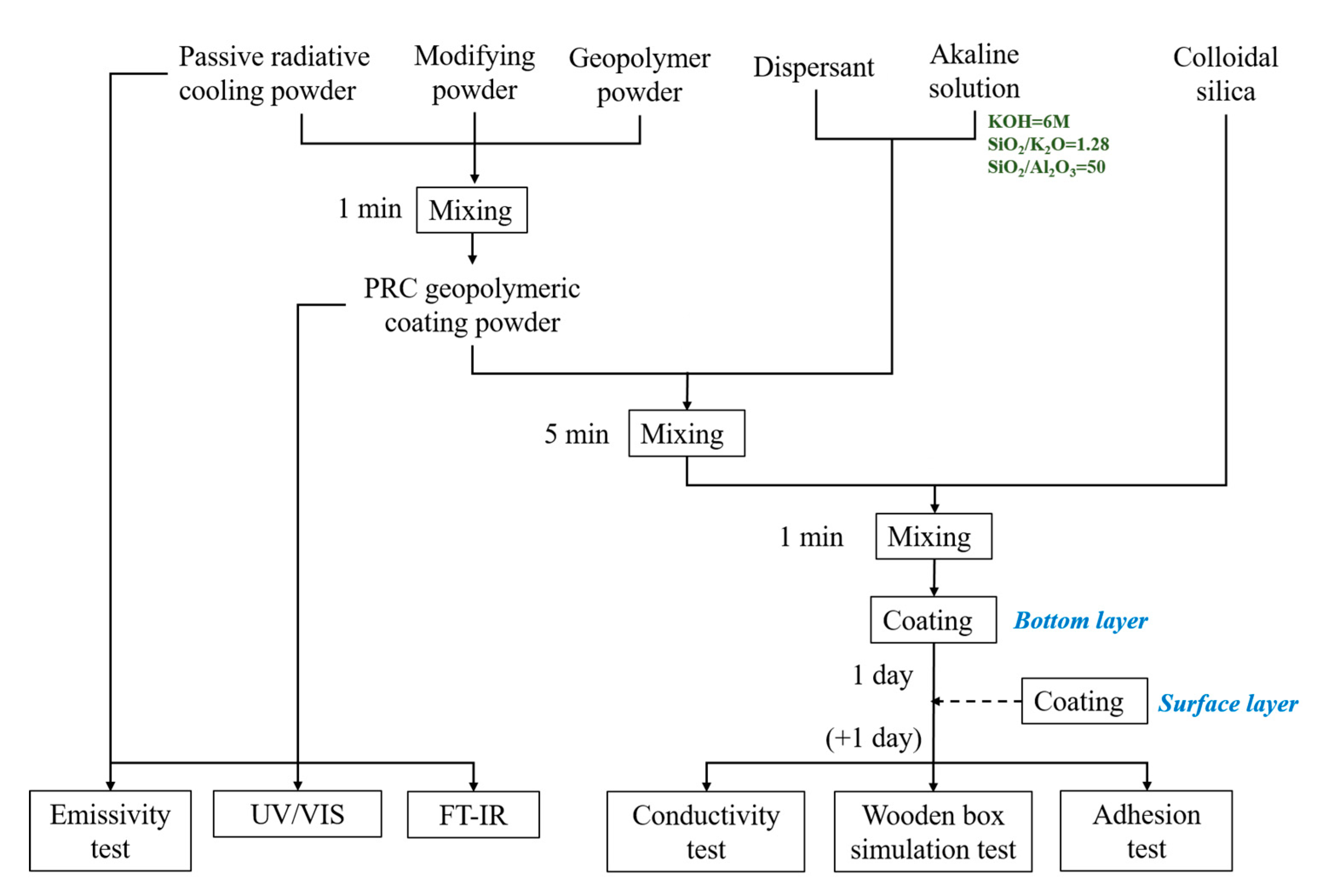
Figure 1.
Overall experiment procedure.
Figure 1.
Overall experiment procedure.
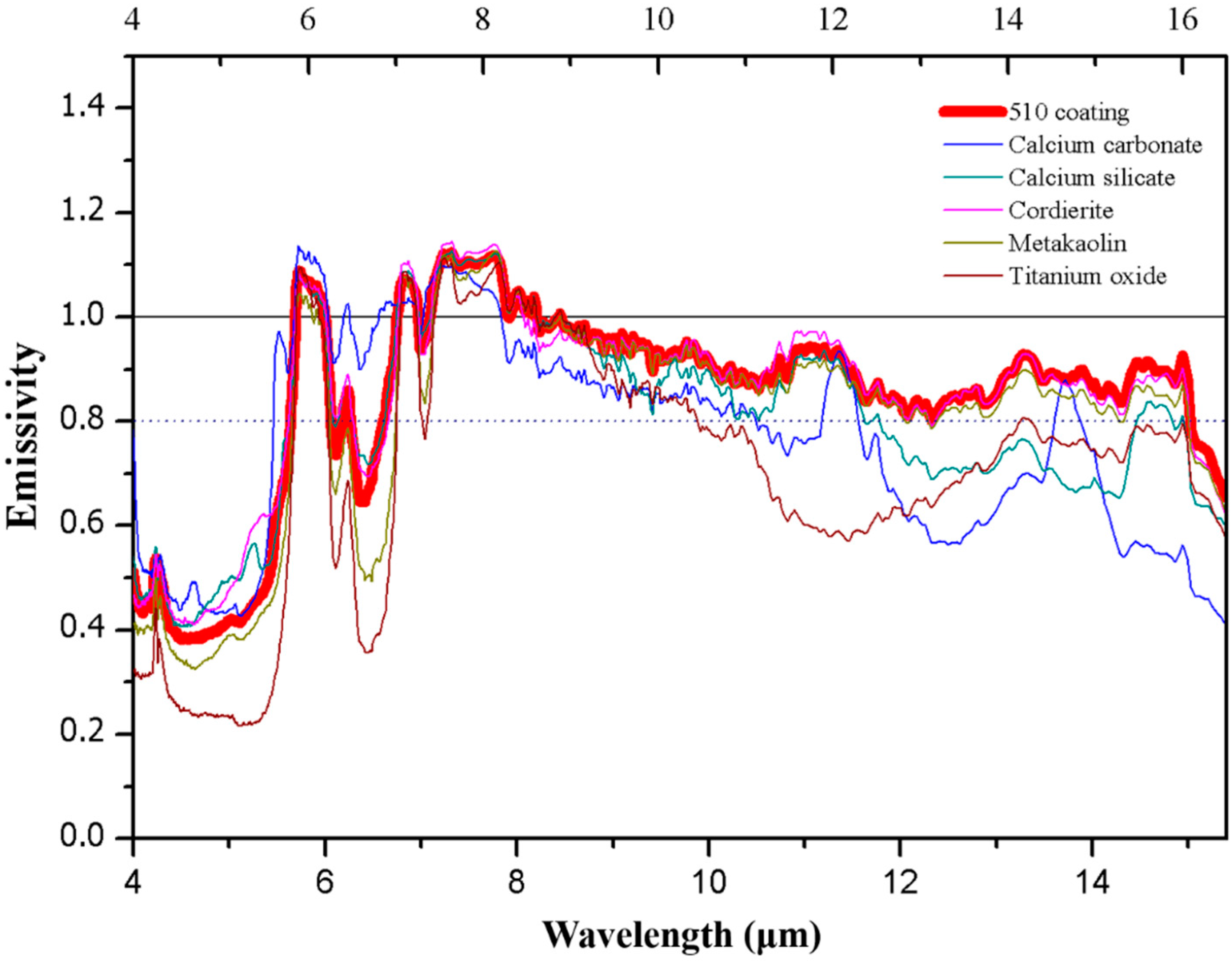
Figure 2.
The emissivity of 510 coating powder and its composition.
Figure 2.
The emissivity of 510 coating powder and its composition.
Figure 3.
The emissivity of BOF coating powder and its composition.
Figure 3.
The emissivity of BOF coating powder and its composition.
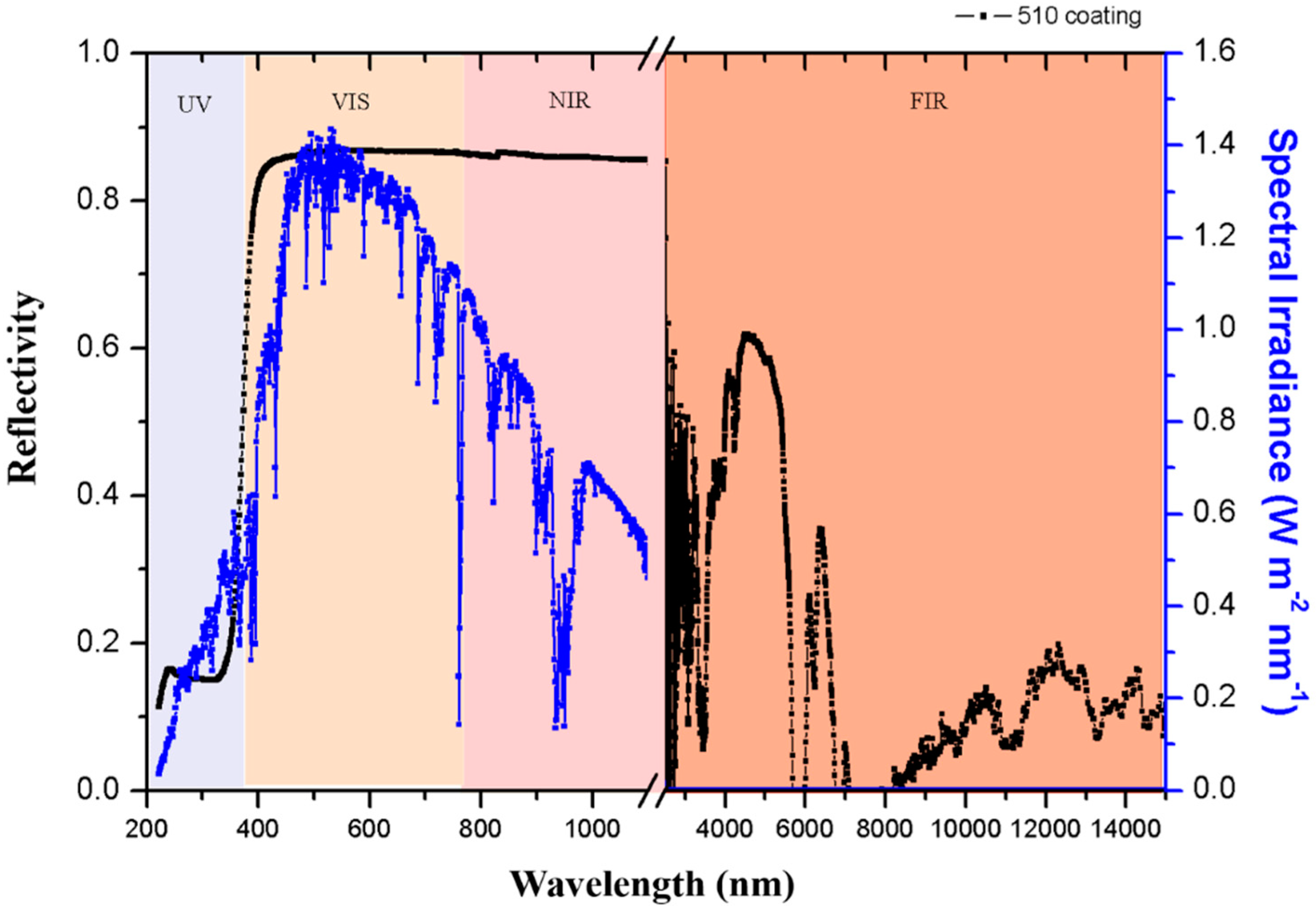
Figure 4.
Reflectivity at UV-VIS-NIR-FIR wavelengths.
Figure 4.
Reflectivity at UV-VIS-NIR-FIR wavelengths.
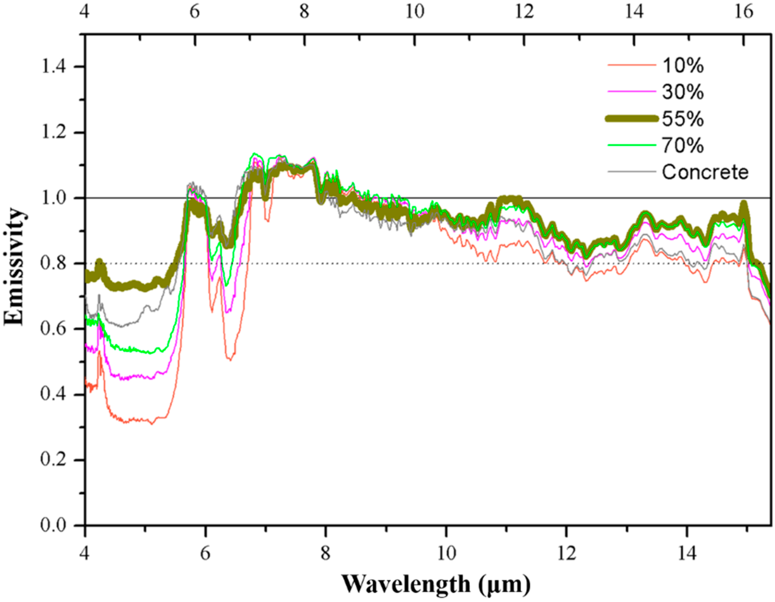
Figure 5.
The emissivity of different amounts of basic oxygen furnace slag (BOFs) added to the BOF coating.
Figure 5.
The emissivity of different amounts of basic oxygen furnace slag (BOFs) added to the BOF coating.
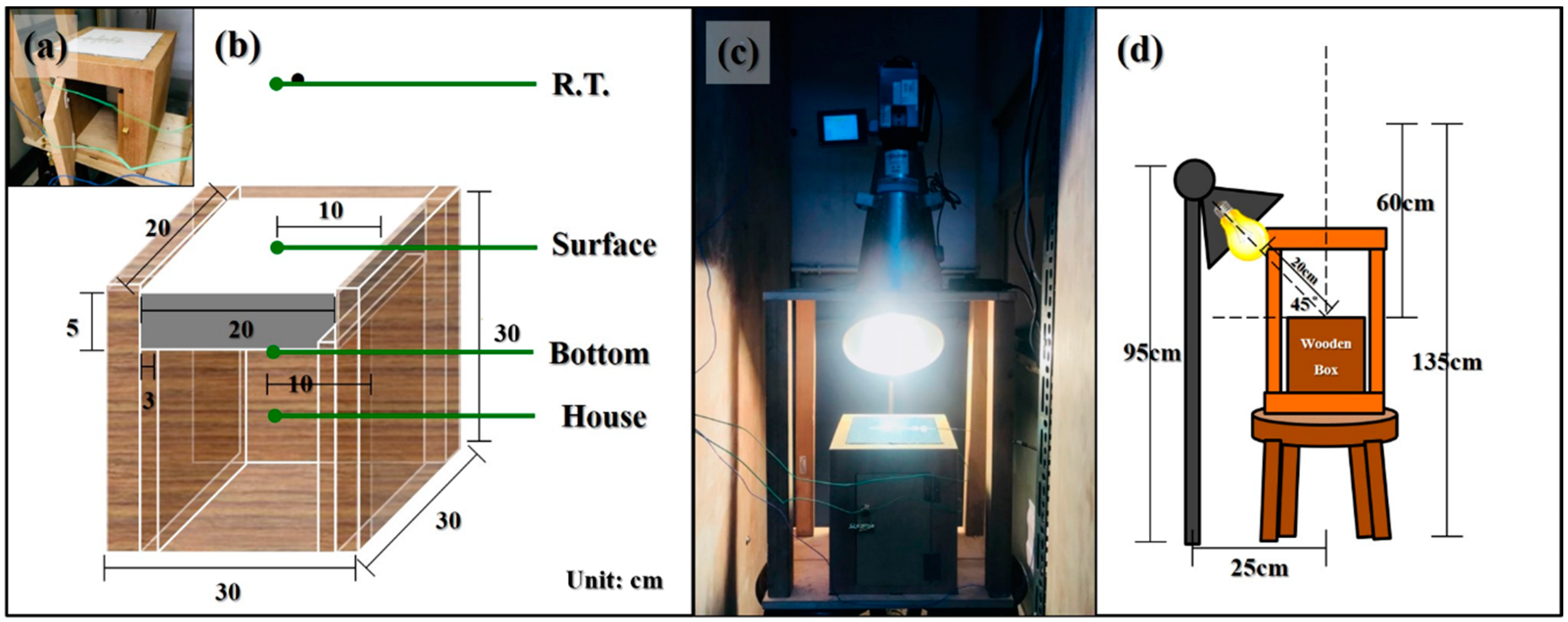
Figure 6.
(a) Photo of the wooden box. (b) Perspective illustration of the wooden box. (c) Photo of the apparatus working in progress. (d) Perspective illustration of the apparatus.
Figure 6.
(a) Photo of the wooden box. (b) Perspective illustration of the wooden box. (c) Photo of the apparatus working in progress. (d) Perspective illustration of the apparatus.
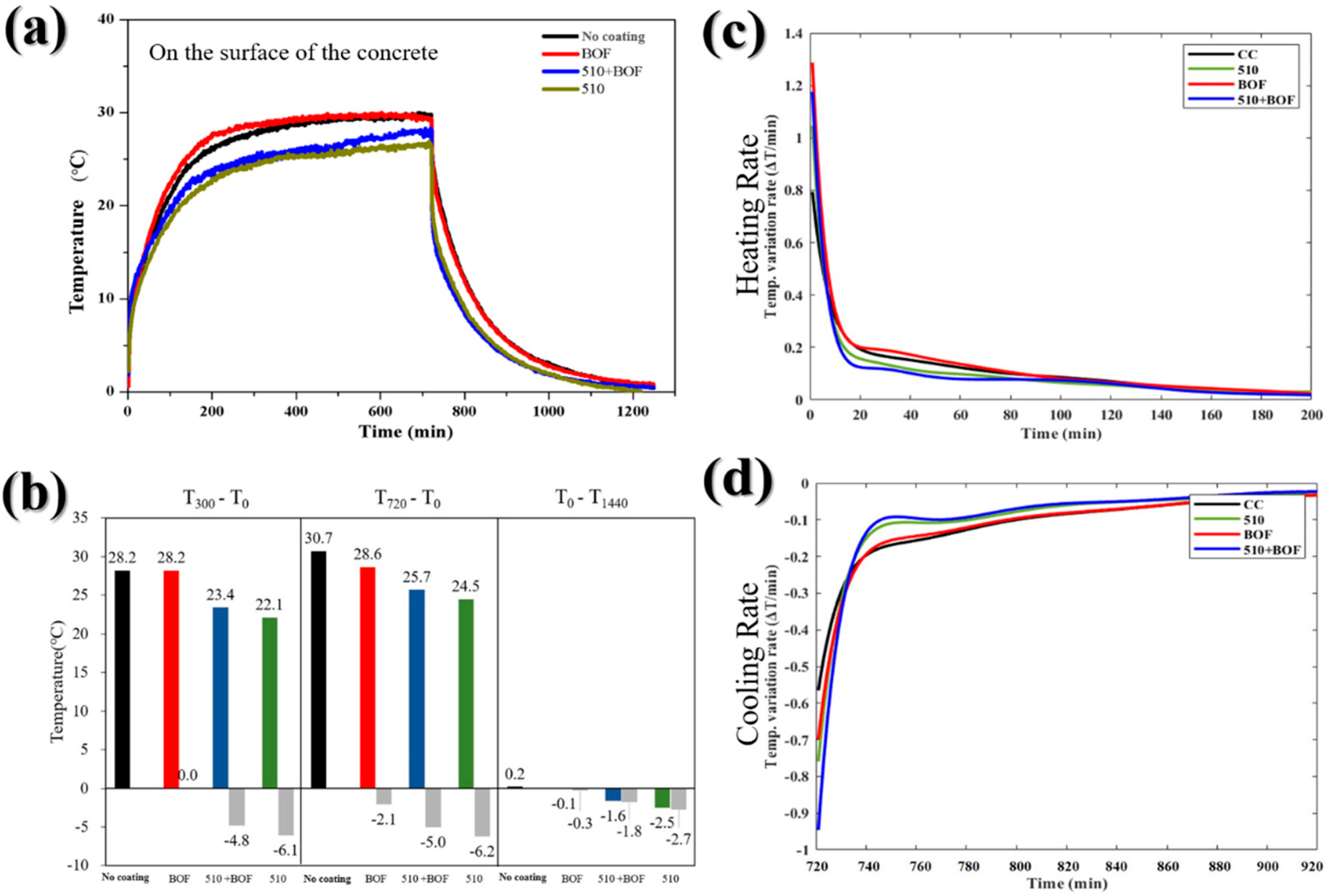
Figure 7.
The influence of BOF, 510, and 510+BOF coatings on the concrete’s surface: (a) the temperature variation in daytime and nighttime; (b) temperature difference at 300, 720, and 1440 min; (c) heating rate; (d) cooling rate.
Figure 7.
The influence of BOF, 510, and 510+BOF coatings on the concrete’s surface: (a) the temperature variation in daytime and nighttime; (b) temperature difference at 300, 720, and 1440 min; (c) heating rate; (d) cooling rate.
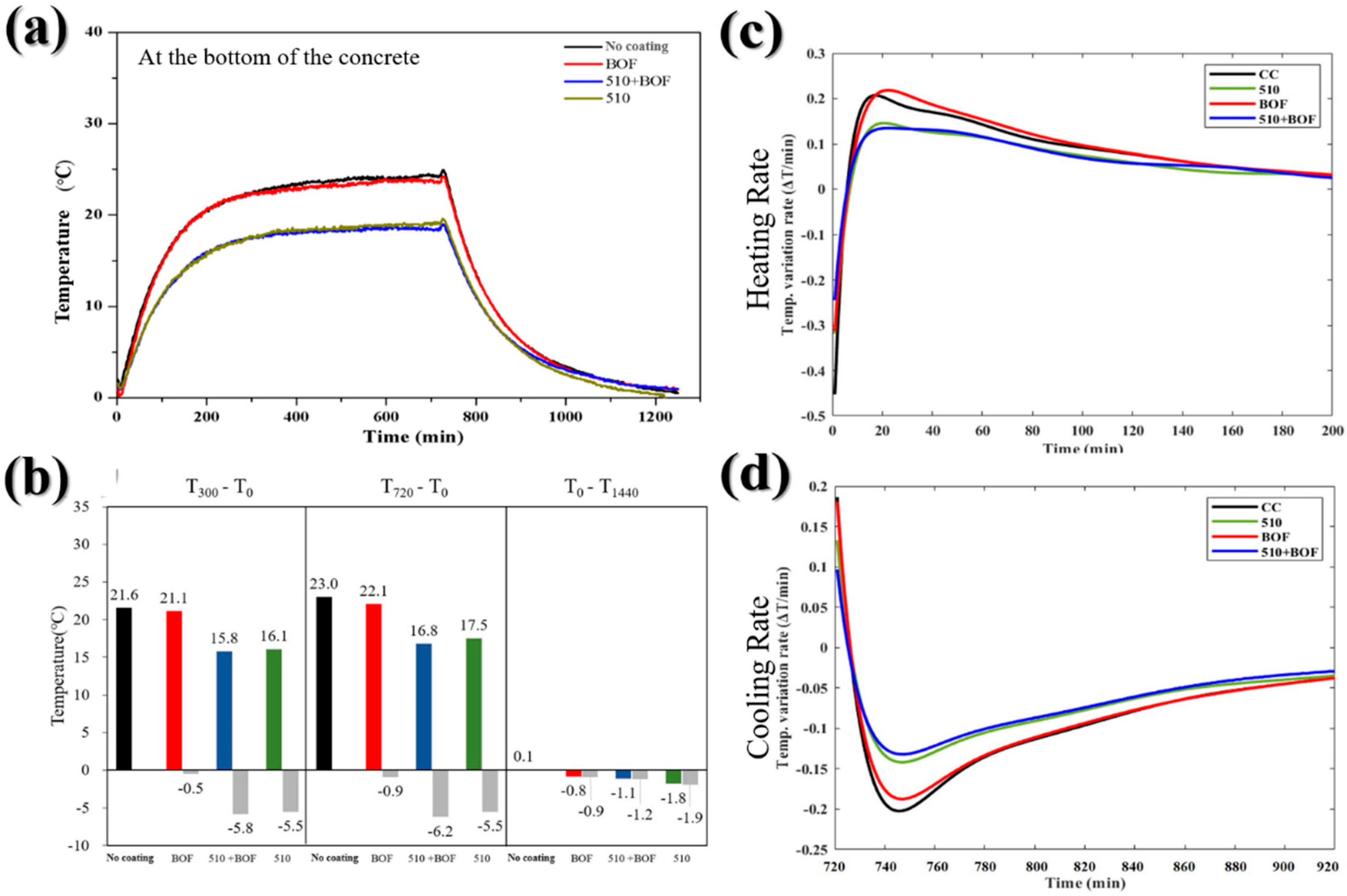
Figure 8.
The influence of BOF, 510, and 510+BOF coatings on the bottom of the concrete: (a) the temperature variation in daytime and nighttime; (b) temperature difference at 300, 720, and 1440 min; (c) heating rate; (d) cooling rate.
Figure 8.
The influence of BOF, 510, and 510+BOF coatings on the bottom of the concrete: (a) the temperature variation in daytime and nighttime; (b) temperature difference at 300, 720, and 1440 min; (c) heating rate; (d) cooling rate.
Figure 9.
The influence of BOF, 510, and 510+BOF coatings in internal wooden box: (a) the temperature variation in daytime and nighttime; (b) the temperature difference at 300, 720, and 1440 min; (c) heating rate; (d) cooling rate.
Figure 9.
The influence of BOF, 510, and 510+BOF coatings in internal wooden box: (a) the temperature variation in daytime and nighttime; (b) the temperature difference at 300, 720, and 1440 min; (c) heating rate; (d) cooling rate.
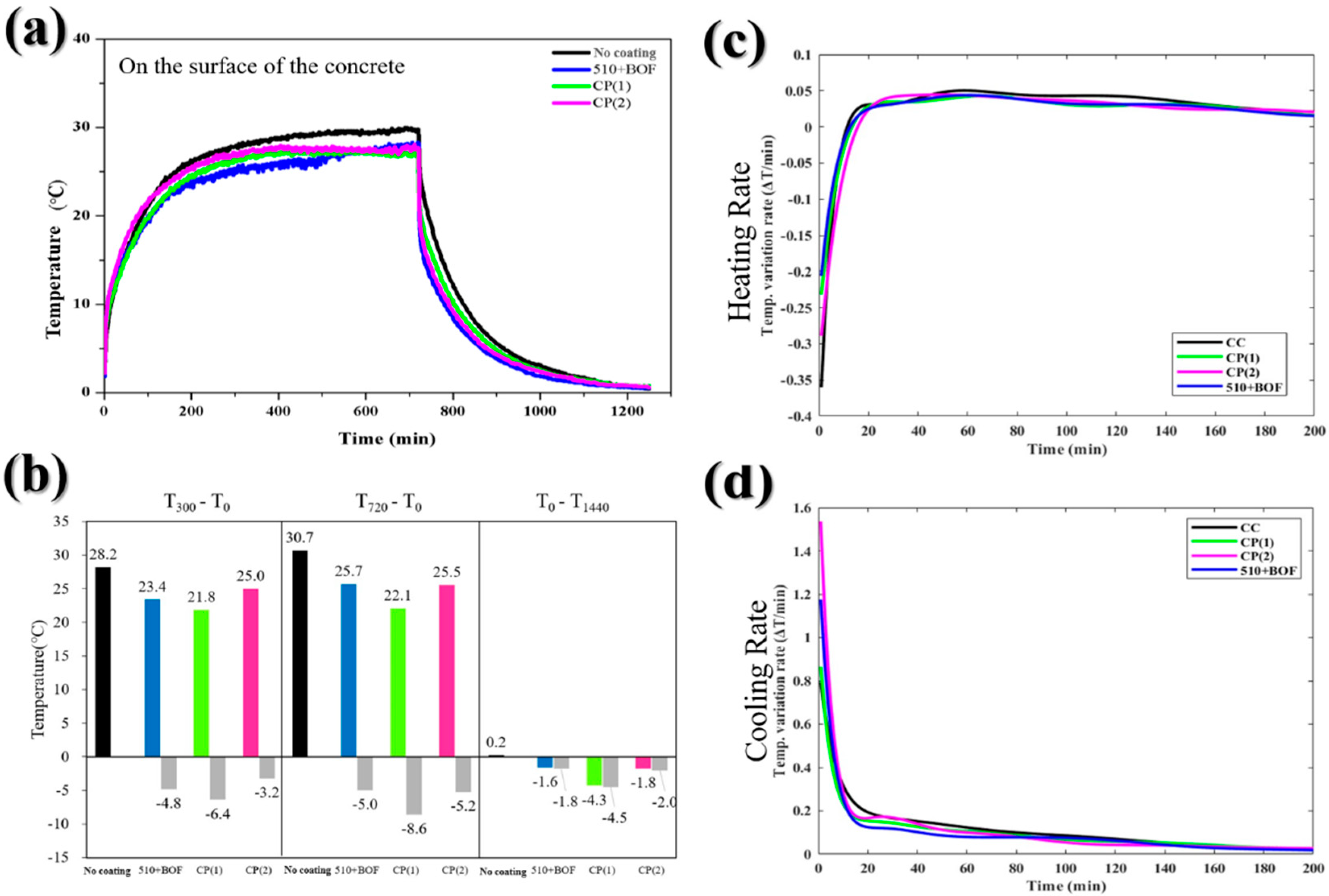
Figure 10.
The influence of double-layer coating and commercial paint on the concrete’s surface: (a) the temperature variation in daytime and nighttime; (b) the temperature difference at 300, 720, and 1440 min; (c) heating rate; (d) cooling rate.
Figure 10.
The influence of double-layer coating and commercial paint on the concrete’s surface: (a) the temperature variation in daytime and nighttime; (b) the temperature difference at 300, 720, and 1440 min; (c) heating rate; (d) cooling rate.
Figure 11.
The influence of the double-layer coating and commercial paint on the bottom of the concrete: (a) the temperature variation in daytime and nighttime; (b) the temperature difference at 300, 720, and 1440 min; (c) heating rate; (d) cooling rate.
Figure 11.
The influence of the double-layer coating and commercial paint on the bottom of the concrete: (a) the temperature variation in daytime and nighttime; (b) the temperature difference at 300, 720, and 1440 min; (c) heating rate; (d) cooling rate.
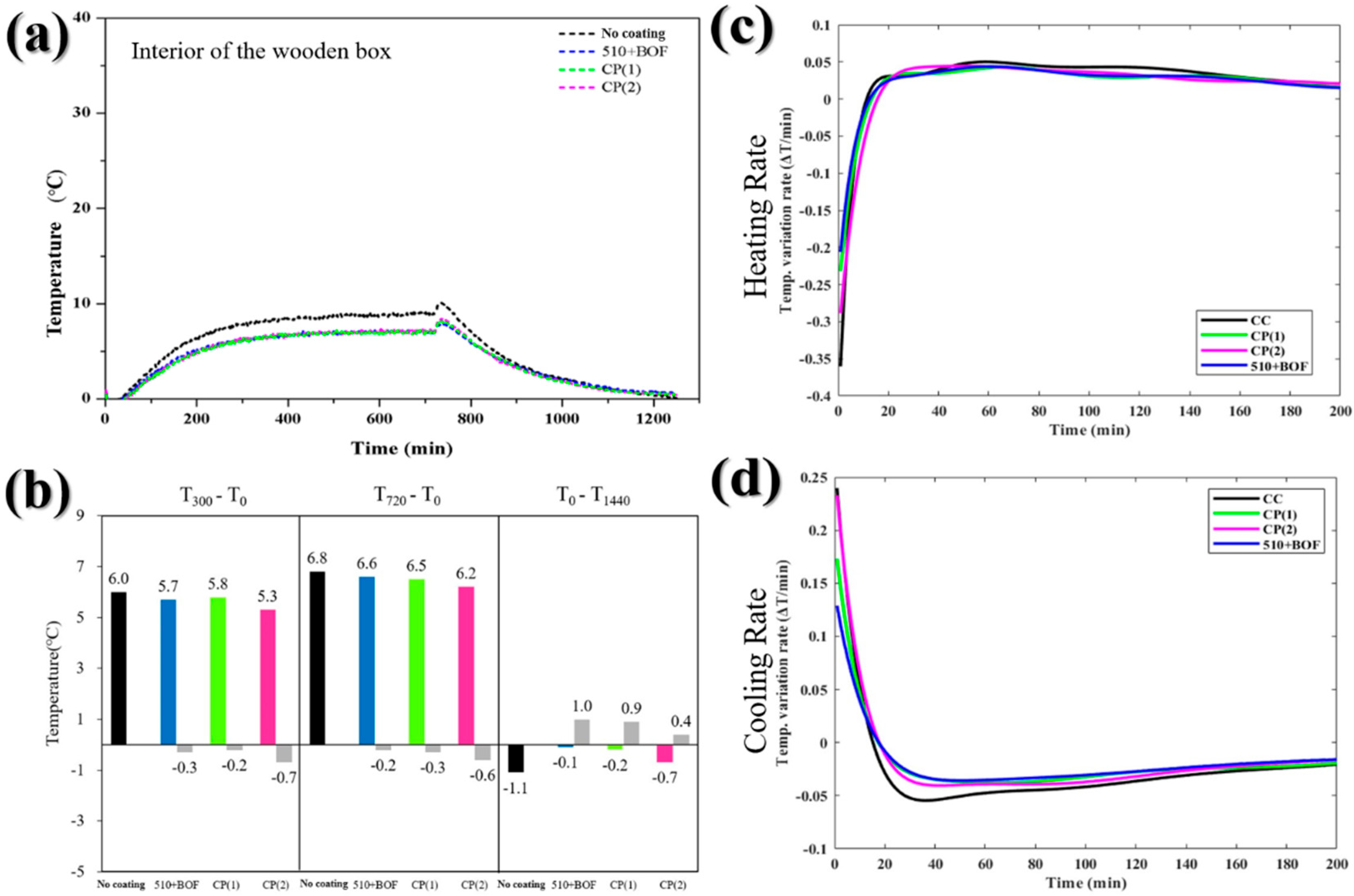
Figure 12.
The influence of the double-layer coating and commercial paint in internal wooden box: (a) the temperature variation in daytime and nighttime; (b) the temperature difference at 300, 720, and 1440 min. (c) heating rate; (d) cooling rate.
Figure 12.
The influence of the double-layer coating and commercial paint in internal wooden box: (a) the temperature variation in daytime and nighttime; (b) the temperature difference at 300, 720, and 1440 min. (c) heating rate; (d) cooling rate.
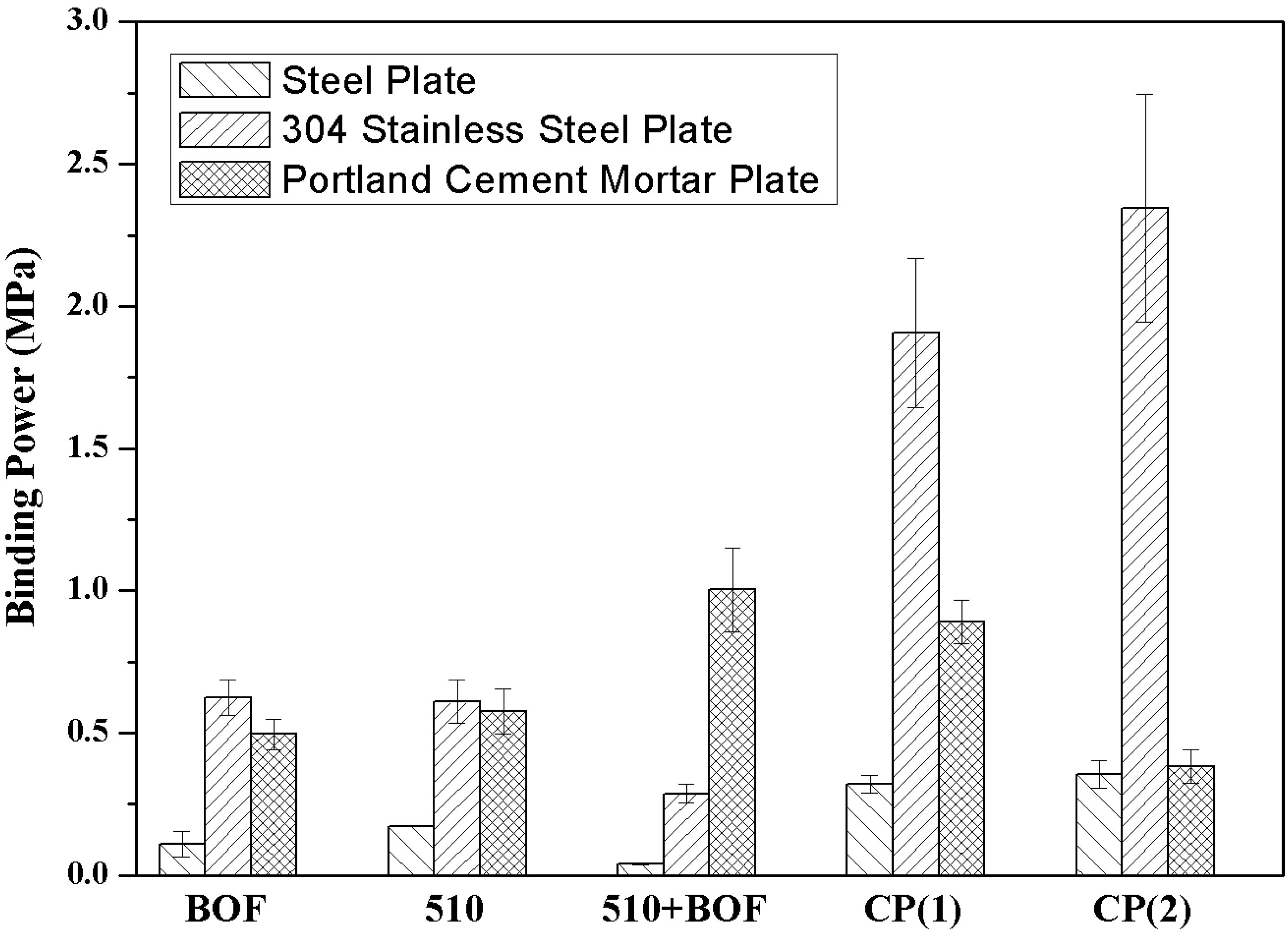
Figure 13.
The adhesion of geopolymeric coatings and commercial paintings on different substrates.
Figure 13.
The adhesion of geopolymeric coatings and commercial paintings on different substrates.
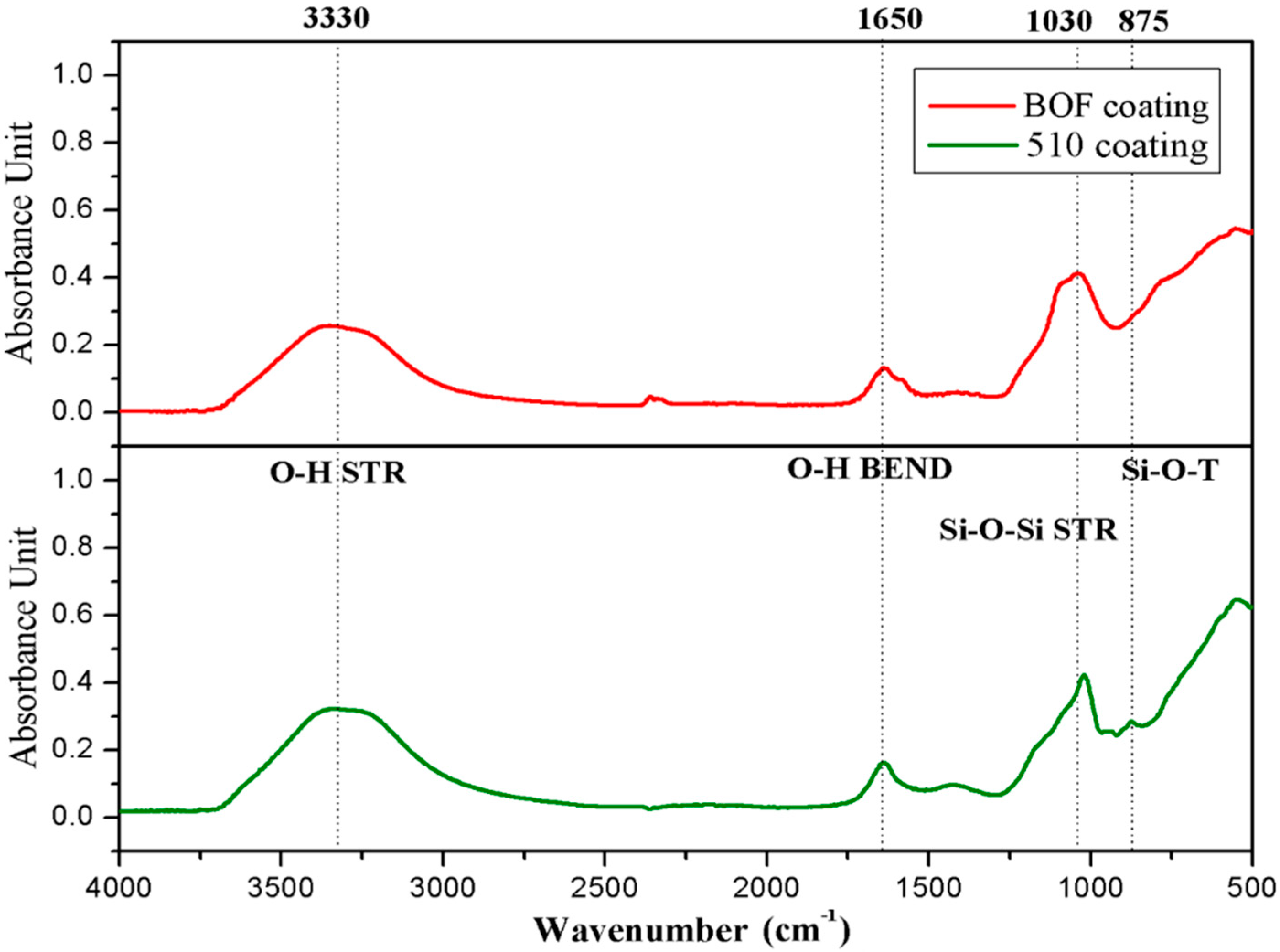
Figure 14.
The FT-IR spectra of geopolymeric coating.
Figure 14.
The FT-IR spectra of geopolymeric coating.
Table 1.
Chemical composition and D50 of materials.
Table 1.
Chemical composition and D50 of materials.
| | Composition (wt.%) | SiO2 | Al2O3 | TiO2 | Fe2O3 | K2O | CaO | ZnO | MgO | Others | L.O.I | D50 (μm) |
|---|
| Material | |
|---|
| Metakaolin | 55.2 | 39.6 | 2.4 | 0.7 | - | - | - | - | 0.1 | 1.5 | 4.7 |
| Calcium silicate | 58.3 | 33.1 | - | 2.7 | 1.5 | 0.3 | - | - | 1.7 | 0.6 | 27.1 |
| Cordierite | 47.4 | 31.5 | - | - | - | - | - | 11.3 | 6.1 | 2.8 | 48.9 |
| Titanium oxide | 0.6 | 1.3 | 96.3 | - | - | - | 0.3 | - | 1.1 | 0.3 | 0.4 |
| Calcium carbonate | 0.6 | - | - | - | - | 56.5 | - | 4.4 | - | 37.5 | 24.9 |
| BOF slag | 11.5 | 4.5 | 0.5 | 21.6 | - | 39.4 | - | 6.4 | 12.1 | 3.9 | 13.6 |
Table 2.
Composition of the white cordierite coating.
Table 2.
Composition of the white cordierite coating.
| Code | Powders (wt.%) | Solution (wt.%) |
|---|
| Cordierite | Calcium Carbonate | Titanium Oxide | Metakaolin | Calcium Silicate | Alkaline Solution | Colloidal Silica | Dispersant |
|---|
| 510 | 30 | 20 | 20 | 20 | 10 | 40 | 40 | 1 |
Table 3.
Composition of the basic oxygen furnace (BOF) inorganic coating.
Table 3.
Composition of the basic oxygen furnace (BOF) inorganic coating.
| Code | Powders (wt.%) | Solution (wt.%) |
|---|
| BOFs | Metakaolin | Calcium Silicate | Alkaline Solution | Colloidal Silica | Dispersant |
|---|
| BOF | 55 | 35 | 10 | 40 | 40 | 1 |
Table 4.
Composition of improved BOF inorganic coating.
Table 4.
Composition of improved BOF inorganic coating.
| Code | Powders (wt.%) | Solution (wt.%) |
|---|
| BOFs | Metakaolin | Calcium Silicate | Alkaline Solution | Colloidal Silica | Dispersant |
|---|
| BOF-10% | 10 | 80 | 10 | 40 | 40 | 1 |
| BOF-30% | 30 | 60 |
| BOF | 55 | 35 |
| BOF-70% | 70 | 20 |
Table 5.
Mean emissivity of 510 and BOF powders and their composition.
Table 5.
Mean emissivity of 510 and BOF powders and their composition.
| Mean Wavelength | 510 Coating | Calcium Carbonate | Calcium Silicate | Cordierite | Metakaolin | Titanium Oxide | BOF Coating | BOFs |
|---|
| 8~13 μm | 0.92 | 0.81 | 0.88 | 0.93 | 0.91 | 0.80 | 0.95 | 0.92 |
| 2.5~15.4 μm | 0.87 | 0.65 | 0.63 | 0.64 | 0.59 | 0.51 | 0.75 | 0.82 |
Table 6.
Mean emissivity of different amounts of BOFs added to the BOF coating.
Table 6.
Mean emissivity of different amounts of BOFs added to the BOF coating.
| | BOFs Addition | 10% | 30% | 55% | 70% | Concrete |
|---|
| Mean Wavelength | |
|---|
| 8~13 μm | 0.93 | 0.96 | 0.97 | 0.98 | 0.91 |
| 2.5~15.4 μm | 0.73 | 0.75 | 0.80 | 0.78 | 0.71 |
Table 7.
Conductivity of one-layer and double-layer coatings on Portland cement concrete.
Table 7.
Conductivity of one-layer and double-layer coatings on Portland cement concrete.
| Code | Non-Coating | BOF | 510 | 510+BOF |
|---|
| Conductivity (W/m2k) | 1.86 | 2.27 | 2.00 | 2.26 |
Table 8.
Conductivity of 510+BOF coatings compared with two different commercial coating on Portland cement concrete.
Table 8.
Conductivity of 510+BOF coatings compared with two different commercial coating on Portland cement concrete.
| Code | Non-Coating | 510+BOF | CP(1) | CP(2) |
|---|
| Conductivity (W/m2k) | 1.86 | 2.26 | 2.00 | 2.16 |


