Abstract
One of the basic tasks of powered roof support is to protect the longwall excavation against deformation of the rock mass during the underground exploitation of hard coal. The behavior of the rock mass during mining is difficult to predict. Therefore, the loads acting on the support are diverse in terms of nature, direction and force. The dynamic load resulting from rock bursts, relaxation and tremors may lead to particularly dangerous consequences involving the functionality of the workings and the safety of the crew. The powered roof support will function properly only if the elements dynamically loaded are under control at the moment of impact. The article presents the results of tests of the basic powered roof support’s element − a hydraulic leg impacted by dynamic load. The source of the load was a free falling impact mass dropped from a certain height. The tests covered the actual hydraulic leg with all hydraulic equipment used in the powered roof support. During the tests, the original measurement-recording system developed by the authors was used, in which, among others, a high-speed dynamic camera was used to record movements of the leg’s elements. The original research methodology developed together with the measurement system enabled the registration of many parameters of the leg’s work under dynamic load. In particular, this applies to time series of pressure in the leg and the value of its withdrawal depending on the energy of the impact. The individual phases of the leg’s work were also registered, including the opening and closing of the safety valve protecting the leg against overloading. The obtained results broaden knowledge in the field of hydraulic legs used in the mining support under dynamic load. At the same time, they are a valuable source of information for mine maintenance services and should be applied to the design process, selection and operation of a powered roof support in dynamic conditions. The subject of the article fits in with the philosophy of sustainable development, especially in the field of full use of options of the support and ensuring safe and environmentally friendly mining processes.
1. Introduction
Difficult and not entirely predictable mining and geological conditions in which the underground exploitation of hard coal is conducted pose a threat to the working environment of the crew and machines, therefore proper safety system and protection measures are crucial. The randomness of external conditions necessitates the use of reliable and high technical parameters of machines. This particularly applies to mining roof supports [1,2,3,4,5,6,7,8]. Their primary task is to protect mining excavations against deformation caused by the rock mass [1,2,3,4,5,6,7,8,9,10]. Therefore, in order to protect mine workings, various types of mining roof support are used [1,2,3,11,12]. The roof support is also subject to a number of impacts that may lead to its failure. The support is exposed to various hazards, mainly fire and ventilation hazards [13,14,15,16,17,18,19].
One particularly dangerous hazard is the methane hazards associated with the outflow of large amounts of gas to the mine atmosphere and often also to the environment [13,14,15,18,19]. Therefore, a well-designed and exploited mining support has a significant impact on the sustainable development of the mining industry. It will ensure the safety of employees and positively affect the environment. In particular, this concerns the efficiency of the mining process, with which methane emissions are strictly related. Consequently, it is crucial to conduct research aimed at ensuring an effective use of machines.
In the case of longwall workings in which the main mining process is carried out, the basic type of support is a powered roof support. It consists of powered sections. Figure 1 [20] presents the powered roof support section in a longwall working with its main mechanical, hydraulic and control elements.
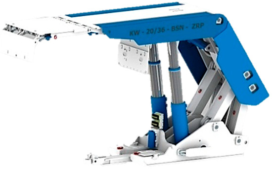
Figure 1.
A powered roof support section in longwall working during operation. Modified from [20].
The support sections, treated as machines, consist of three basic systems. These are mechanical, hydraulic and control systems. For effective and reliable operation, the importance of these systems is practically comparable. However, the hydraulic system and its control system are of particular importance due to the efficiency of the operation process itself, and the possibility of impact on the operating parameters of the section and the support. In this respect, hydraulic legs fulfil are executive elements that largely determine the effectiveness of the entire support being exposed to static and dynamic loads [6,7,20,21].
Both types of load impacting on the support are random because it is difficult to accurately determine the deformation impact of the rock mass on the longwall, and thus also on the support. It is obvious that dynamic load may lead to much greater damage to the support. Its sources are rock bursts, rock mass rests and tremors [10,12,22,23,24,25]. Such a load is defined as a sudden action on the support of external or inertial force resulting from the acceleration of its mass [21,22,23,24]. Dynamic loads acting on the longwall support usually have an impulse nature [11,12,24,26,27]. It consists in a short-term sudden action of external force or pulsation load associated with dynamic movements of the rock mass [12,22,27,28]. The purpose of the roof support is to transfer these loads and limit damage to the longwall working as much as possible.
This task is mainly carried out by the support’s legs and the hydraulic system together with the entire control and safety system. Proper operation, condition and maintenance of safety valves are extremely important for the whole system. Their task is to prevent a critical pressure increase in the hydraulic system, which could lead to its damage or destruction [11,27]. Properly functioning safety valves should make the support yielded by reducing the volume of the hydraulic fluid, and thus dissipate energy resulting from its load. This, in turn, should effectively limit the negative impact of the deformation caused by the rock mass on the longwall working. It can therefore be assumed that the importance of safety valves for effective and safe operation of sections and the entire support is crucial. This particularly refers to dynamic loads impacting on the support. The reliability and effectiveness of the applied safety systems of hydraulic legs should constantly improve. This is the consequence of common occurrence of loads, mainly impulse generated by rock mass. For this reason, it is necessary to conduct research in order to learn the characteristics of the work of the legs together with the safety valves used in the powered roof support. These characteristics determine the time series of pressure in the legs depending on the safety system applied and the energy resulting from the load.
This type of research is desirable and fundamental as mining exploitation is carried out in increasingly unfavorable mining and geological conditions. Greater depths of exploitation, tectonic disturbances in the rock mass and high intensity of exploitation cause the mining process to be inseparable from the occurrence of dynamic phenomena. In addition, the mining support, in accordance with the new regulations [29,30,31], should also support the mining process itself. Appropriate yielding should ensure safe and effective exploitation and its cooperation with the rock mass. The main element yielding the powered roof support is the hydraulic leg and its safety system. Therefore, it is necessary to determine the impact of dynamic load on the work of a leg and the entire hydraulic system.
The paper presents the results of tests on hydraulic leg together with the hydraulic system under dynamic load. The source of the load was the impact of free falling mass. The research was based on the new research methodology developed by the authors. In particular, it included the use of an innovative system for registering a leg’s operation parameters as well as its control and safety system. The high-speed dynamic camera enabled the research team to register movements of individual elements of the leg and to unambiguously determine the size of slide in the leg during the dynamic load. It was also possible to follow the operation of the safety valve. In particular, this operation concerns its opening and closing as well as the outflow of hydraulic fluid. In addition to determining the leg’s performance characteristics, it was also possible to evaluate the effectiveness of its safety system (the effectiveness of the safety valve) and to assess the functioning of the entire hydraulic system (in terms of its tightness, resistance to damage and smooth movements during slides).
The developed methodology, the research carried out and the obtained results confirmed the validity of the research assumptions. In relation to the research conducted so far in this respect [16,19], a much more detailed analysis of the operation of the leg and the entire hydraulic system together with the safety valve was carried out. It significantly extends this knowledge in the field of hydraulic leg and the safety system subjected to dynamic load. Obtained results should therefore, in a wide range, be applied to the design process, selection and operation of powered roofs in conditions of dynamic impact of the rock mass.
2. Research Methodology
Research on the impact of dynamic load on the work parameters of the mining powered roof support’s hydraulic leg was carried out on a test stand at the Opava TLO in the Czech Republic. The tests were carried out for the Hydrotech-19/36-POz roof support, together with hydraulic and safety systems [30]. The leg was subjected to a dynamic load, free-falling mass dropped from a certain height. The testing station, its layout and basic components are shown in Figure 2.
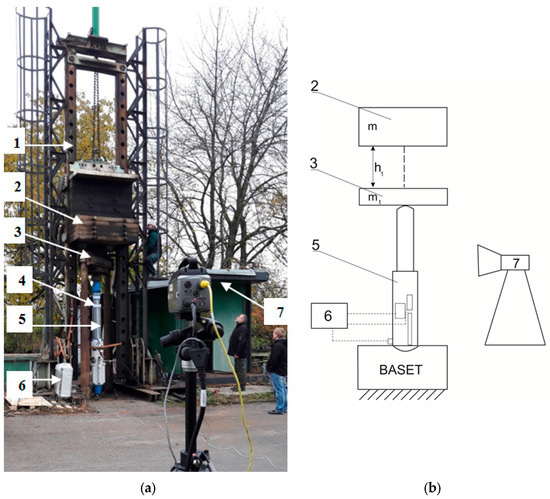
Figure 2.
Testing station for hydraulic leg with the impact of free-falling mass (a) and its layout (b): 1—impact weight guides, 2—impact mass, 3—traverse, 4—bolt blocking the traverse in the station frame, 5—hydraulic leg, 6—measuring system, 7—high-speed camera.
As mentioned, the source of the load impacting on the leg was impact mass (m) falling freely from selected height (h). The impact mass (2) falls on the traverse (3) located on the hydraulic leg (5) from different heights in relation to the top of the leg. The volume of the impact mass and the height of its drop determine the energy of the impact, which is calculated from the following equation:
where m is impact mass (drop weight), kg, v is speed at which the drop weight hits the mass of the traverse, m/s, h is impact mass drop height, m and g is gravitational acceleration equal to 9.81 m/s2.
The value of the speed at which the impact mass hits the traverse is calculated as follows:
The energy of an impact acting on the leg is calculated applying the principle of momentum, according to the following equation:
where mT is cross-bar mass, kg and vu is impact mass velocity, m/s.
Taking into account equation (3), the dependence on the kinetic energy of stroke (Eku) can be determined as follows:
In accordance with the presented diagram, the test consisted in axial loading of the hydraulic leg with impact mass (m) falling from a specified height (h) on a traverse resting on the leg, weighing 1800 kg (mT). In this case, the weight of the impact mass was 20,000 kg. The tests were carried out for seven different heights from which the impact mass was dropped.
These heights were selected so that the characteristics of the determined parameters of the leg’s work together with the hydraulic system were as close as possible to the real range of changes in the impact energy.
During the tests, temporary changes in the pressure value in the space under the piston of the hydraulic leg and displacement of its elements were recorded. The innovative measurement-recording system [31] and a high-speed dynamic camera were used to record these quantities. For fast-changing shots, a Phantom camera, model v9.1 with a recording speed of 3000 frames per second was used. The use of this camera has also made it possible to record the opening and closing moments of the safety valve and the outflow of hydraulic fluid from this valve.
The measurement and recording system used in this research [31] enabled direct registration of pressure waveforms at many points of the leg‘s hydraulic system. It is built from a control and intermediary module, enabling the examination of individual control elements of the powered roof support and its hydraulic components. It uses National Instruments cRIO9030 cards and features two different operator interfaces. Communication with the system takes place via an Ethernet link, and its software was made in the LabVIEW environment [31].
The test was based on an axial loading with a dynamic impulse (drop-weight) of the hydraulic leg. A safety valve and valve block were connected to the space under the piston of the leg. A pressure sensor is located in the connection that links the safety valve with the under-piston space of the leg. The pressure sensor was connected to the space under the piston of the leg and the valve block. The tests were conducted for a leg with an extended piston with a height of 2.6 m. These dimensions were maintained during all tests. The length of the leg’s extension has a significant impact on the results obtained. The tests adopted this specific height due to the fact that in practice such a length occurs most often.
One of the sensors for measuring the pressure in the under-piston space of the leg (its results are presented later in the paper) and the mounted safety valve are shown in Figure 3.
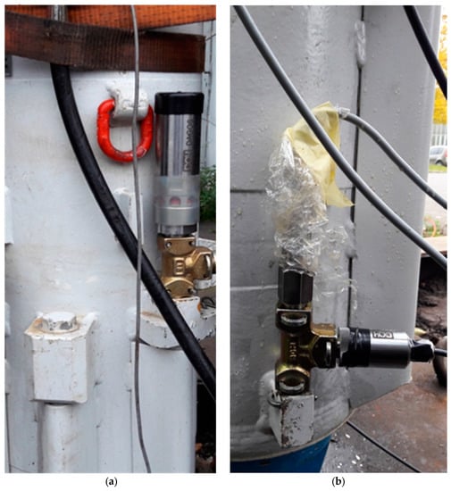
Figure 3.
A safety valve (a) installed in the tested hydraulic leg and the pressure sensor (b) for measurements in the space under the piston.
The main purpose of the conducted research was to determine the dynamic characteristics of the work of the hydraulic leg loaded with a free-falling mass. These characteristics determine the temporal changes in hydraulic fluid pressure in the leg’s operating space during load. In addition, the displacement of the leg’s piston with regard to movements of the entire leg during the test was determined. Determination of displacements of additional points located on the leg’s casing enabled a very accurate analysis of piston withdrawal during load. The leg behaves like a spring system and as a result of the impact load, in addition to the movement of the piston, what leads to movements of the entire leg and vibrations of the testing station. These additional movements made it possible to determine the actual values of the slid during the load. This was possible thanks to the use of a high-speed dynamic camera and the analysis of displacements in the leg.
The kinetic energy of the hydraulic leg’s mass is transmitted by the drop weight (impact mass m) to the traverse and then to the tested leg. This energy causes the piston to move in the leg, and thus increase the pressure in the cylinder. When pressure reaches the value of the safety valve setting, the valve opens and the fluid outflows from the leg’s cylinder. The outflow causes further movement of the piston and a decrease in the pressure in the cylinder. When its value drops below the set value, the safety valve closes and the fluid stops flowing.
A significant part of the impact energy moves the cylinder in the leg. This occurs when the safety valve of the leg is opened. The rest is dispersed in the hydraulic and mechanical system. If the safety valve does not open, the whole energy is supplied by hydraulic and mechanical systems of the leg. It is also worth taking into account that in this energy balance, a part of the energy is dispersed to the testing station (vibrations and elastic deformation of the station’s elements).
Subsequently, after the impact, the drop weight’s movement is stopped, which is synonymous with the loss of kinetic energy by the drop weight. Immediately after that, the elastic energy of the leg’s cylinder and fluid lifts the drop weight. The whole process can be repeated several times until all the energy of the impact is dispersed. Impact weight loading the hydraulic leg causes an increase in pressure in its under-piston space. In contrast, the upward movement results in relief and pressure drop in this space. The dependencies determining the time pressure changes in the space under the piston of the hydraulic leg determine the operating characteristics of the leg at a given impact energy.
3. Results and Discussion
Studies on the impact of dynamic loading on hydraulic leg’s work parameters were performed for seven different values of impact energy. The values resulted from the height of the impact mass drop. The test leg was equipped with a safety valve with a slider-piston construction with a cylindrical spring. During the test, the opening pressure of this valve was set at 400 bar (40 MPa).
The paper presents and describes more precisely the time series of the examined values for three largest impact energies.
Figure 4 shows the time course of pressure changes in a hydraulic leg loaded with a free-falling impact mass dropped from a height of 0.7 m (Eu = 137.3 kJ).
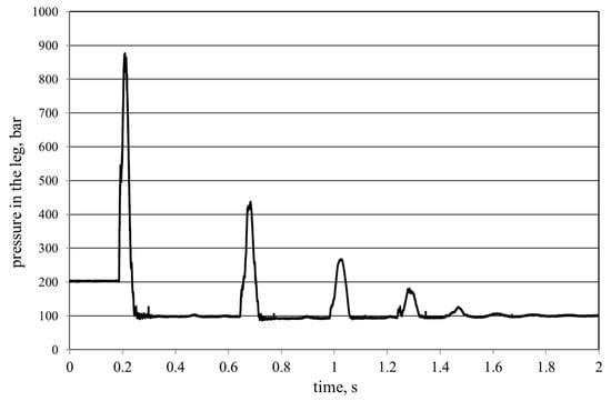
Figure 4.
Performance characteristics of a hydraulic leg loaded with a free-falling impact mass from a height of 0.7 m.
The analysis of the obtained course indicates that a sudden increase in pressure in the working space of the leg occurs as a result of the impact. The maximum value of this pressure in this case was 87.71 MPa. It is noticeable that the initial hit is followed by another one. The leg behaves like a spring system, and the impact mass after rebounding from it after about 0.5 seconds again hits the leg. The maximum pressure in the leg in this case is already significantly lower and amounts to 43.75 MPa. The next impact occurs after about 0.35 seconds, and the maximum pressure reaches 26.7 MPa. The analysis shows dissipation of the impact energy and after about 1.6 seconds the whole system stabilizes.
The application of the high-speed camera allowed us to register movements of individual elements of the leg during the test and to track the operation of its safety valve. The recorded time courses of movements of leg’s elements are shown in Figure 5. The figure also present the places where measurement points were located − the displacement of the leg’s piston (point B) and two points on its casing (points A1 and A2). The registration of the movement of these points was aimed at determining their displacements and applying them during determining the actual movement of the piston. The research team decided to mark two points on the casing of the leg because there was a probability that the outflowing fluid might cover one of them during the opening of the safety valve (Figure 6). Therefore, when analyzing the waveforms of their displacements in Figure 5, they should be treated as points determining the movement of the leg’s casing, as a rigid body. The difference between the displacement of the point B and the points A1 and A2 determines the actual value of sliding the piston in the leg during the test.
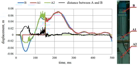
Figure 5.
Trends in the position of points A1, A2, B in the direction of the vertical axis and the difference in position between points A and B during the fall of the impact mass from the height of 0.7 m.
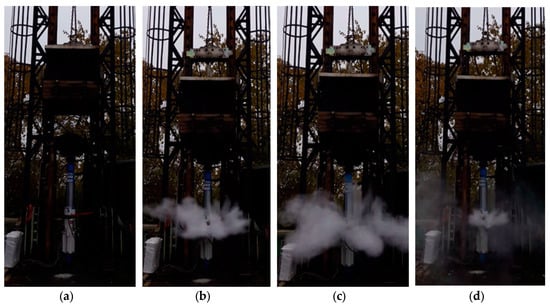
Figure 6.
Four phases of the safety valve’s operation during the tests of the hydraulic leg loaded with impact mass falling from a height of 0.7 m ((a) valve prior opening, (b) initial opening phase, (c) fluid outflow, (d) closing phase).
While analyzing the obtained characteristics, it is possible to determine the individual phases of operation of the hydraulic leg loaded with the impact of the mass. In the first phase, as a result of the drop in the impact weight on the leg, the pressure increased rapidly. When the value of this pressure exceeded the value of the valve setting, the valve was opened and the piston slid. At the same time, as a result of the impact and reflection of the impact mass from the leg, the pressure value increased. At this point, the safety valve closed. Then, the elastic vibrations of the leg’s piston occurred, resulting from the equalization of pressure in the cylinder of the leg. In the presented case, the value of the slide in the leg amounted to 26.6 millimeters, while the safety valve opened after 26 ms from the start of contact of the impact mass with the cross bar. In this case, due to the outflow of fluid from the safety valve, it was impossible to read the displacement of point A2 after 151.3 milliseconds. That is when the relocation of point A1 was recorded.
The use of a high-speed camera allowed to observe the work of the leg and the entire hydraulic system together with the safety valve. The four phases of operation of this valve during the loading of the leg with impact mass falling from the height of 0.7 meters are shown in Figure 6. These phases determine the moment before impact of the impact mass (a), after opening the valve (b), with full outflow of hydraulic fluid from the valve (c) and just before its closing (d).
Temporary waveforms of pressure change in the leg and displacements of its elements when loaded with a mass falling from a height of 0.8 m are presented in Figure 7 and Figure 8.
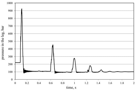
Figure 7.
Performance characteristics of a hydraulic leg loaded with a free-falling impact mass from a height of 0.8 m.
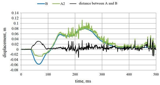
Figure 8.
The course of changes in the position of points A1, A2, B in the direction of the vertical axis and the difference in the position between points A and B during the fall of the impact mass from the height of 0.8 m.
Energy of impact mass reached 157 kJ. The pressure in the leg reached 92.58 MPa, and the slide of piston in the leg was 31.6 mm.
The waveforms obtained indicate that an increase in the impact energy caused the pressure in the hydraulic leg to increase. The maximum value recorded for this case was 92.58 MPa (Figure 7). Subsequent increases in the pressure in the leg as a result of successive impacts of the reflecting impact mass were noted. In this case, three distinct increases in this pressure were recorded.
During the entire tests, the A2 point located on the leg’s casing was visible.
Figure 9 and Figure 10 show the time series of pressure values in the leg and displacement of its elements during loading with impact mass falling from a height of 0.9 m (Eu=176.58 kJ). In this case, the highest pressure value in the leg was recorded during the tests. It amounted to 99.35 MPa (Fig. 9), while the slide of the piston in the leg reached 38 mm.
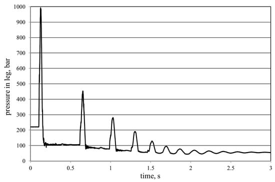
Figure 9.
Performance characteristics of a hydraulic leg loaded with a free-falling impact mass from a height of 0.9 m.
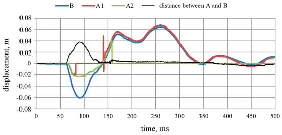
Figure 10.
The course of the changes in the position of points A1, A2, B in the direction of the vertical axis and the difference in the position between points A and B during the fall of the impact mass from the height of 0.9 m.
The analysis of the obtained results indicates that the dynamic load in the form of a shock pulse caused by the free-falling mass cause large pressure rises in the hydraulic leg. The acquired characteristic is similar to the previous examples. Also, in this case, subsequent impacts of the impact mass and increases in the leg’s pressure were registered.
The list of maximum values of the recorded pressure in the leg for the tested impact energy together with the effectiveness of the safety valve is shown in Figure 11. The valve efficiency index was defined as the ratio of the maximum pressure of the fluid in the space under the piston of the leg against the energy of the impact mass.
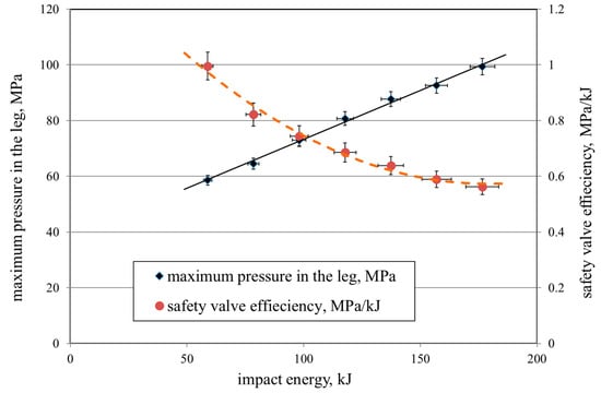
Figure 11.
The maximum pressure values in the tested legs and the corresponding values of the safety valve efficiency index for the tested impact energy.
4. Conclusions
Dynamic load impacting the elements of the roof support leads to dangerous increases in pressure in its hydraulic system. This is confirmed by the performance characteristics of the leg determined during the tests.
Very high increases in pressure values were registered during the tests on the leg type which is widely used in practice. For the highest impact energy (176.58 kJ), a pressure value of up to 99.35 MPa was recorded in the under-piston space of this leg. In mining practice even higher values of energy acting on the support are expected, which can result in even higher pressure values in the legs. Therefore, properly constructed and operating safety valves are crucial for safe operation of individual sections of mining roof supports. The valve applied in the tested leg largely fulfilled its task without damaging the leg.
In each case, this valve worked properly and made it possible to transfer the load through the leg. Its effectiveness is also demonstrated by recorded slides. For low impact energy its efficiency seems sufficient to protect the entire support sections. However, in the case of higher impact energy (above 150 kJ), the efficiency of this valve decreases, which may result in excessive overloading of the leg and its damage. Therefore, it seems reasonable to use more effective methods for securing the legs against higher impact energy.
The results presented in the paper are only a part of the material recorded during the research. They indicate that the developed methodology, and the measurement and recording system work correctly. This is a great opportunity to conduct further research, the aim of which would be to develop an effective wireless control system for the powered roof support unit.
Undoubtedly, further tests of legs and their hydraulic systems under dynamic load should be continued. The presented methodology, and recording and measuring system with a high-speed dynamic camera create very favorable conditions for analyzing the work of the entire hydraulic system of the leg, and in particular the work of the safety valve.
The authors believe that the presented results will contribute to the improvement of work safety and operation of the powered roof support, and thus will improve the efficiency of the entire mining process.
Results of the research should also have a positive impact on the entire mining exploitation process, which is currently perceived as very negatively affecting the natural environment. The use of new effective technical solutions, such as those proposed in this paper, should limit this negative impact. Sustainable development of the economy should mainly be considered by the mining industry in order to improve its image and reduce negative impacts on the environment.
Author Contributions
Conceptualization, D.S. and J.B.; methodology, J.B. and D.S.; software, D.S.; validation, D.S. and J.B.; formal analysis, D.S. and J.B.; investigation, J.B. and D.S.; resources, D.S. and J.B.; data curation, D.S. and J.B.; writing of the original draft preparation, J.B.; writing of review and editing, J.B.; visualization, J.B. and D.S.; supervision, J.B.; project administration, J.B.; funding acquisition, D.S.
Funding
The work was carried out within the project “Innovative electro-hydraulic control system for powered roof support” No. POIR.01.01.01-00-1129/15. The Operational Programme Smart Growth 2014–2020 carried out by the National Centre for Research and Development.
Conflicts of Interest
The authors declare no conflicts of interest.
References
- Brodny, J. Determining the working characteristic of a friction joint in a yielding support. Arch. Min. Sci. 2010, 55, 733–746. [Google Scholar]
- Brodny, J. Tests of Friction Joints in Mining Yielding Supports Under Dynamic Load. Arch. Min. Sci. 2011, 56, 303–318. [Google Scholar]
- Brodny, J.; Tutak, M. Performance characteristics of the friction joint used in the mining support. In Proceedings of the 16th International Multidisciplinary Scientific Geo Conference, Albena, Bulgaria, 28 June–7 July 2016. [Google Scholar]
- Gumuła, S. A new concept of hydraulic mechanized supports resistant to the crumps. Arch. Min. Sci. 2005, 50, 275–288. [Google Scholar]
- Guo, W.B.; Wang, H.S.; Dong, G.W.; Li, L.; Huang, Y.G. A Case Study of Effective Support Working Resistance and Roof Support Technology in Thick Seam Fully-Mechanized Face Mining with Hard Roof Conditions. Sustainability 2017, 9, 935. [Google Scholar] [CrossRef]
- Hussein, M.A.; Ibrahim, A.R.; Imbaby, S.S. Load calculations and selection of the powered supports based on rock mass classification and other formulae for abutartur longwall phosphate mining conditions. J. Eng. Sci. 2013, 41, 1–15. [Google Scholar]
- Liang, Y.; Li, L.; Li, X.; Wang, K.; Chen, J.; Sun, Z.; Yang, X. Study on Roof-Coal Caving Characteristics with Complicated Structure by Fully Mechanized Caving Mining. Shock Vib. 2019, 2019, 6519213. [Google Scholar] [CrossRef]
- Singh, R.; Singh, T.N. Investigation into the behavior of a support system and roof strata during sublevel caving of a thick coal seam. Geotech. Geol. Eng. 1999, 17, 21–35. [Google Scholar] [CrossRef]
- Stoiński, K.; Mika, M. Dynamics of Hydraulic Leg of Powered Longwall Support. J. Min. Sci. 2003, 39, 72–77. [Google Scholar] [CrossRef]
- Brady, B.H.G.; Brown, E.T. Rock Mechanics for Underground Mining; Kluwer Academic Publishers: New York, NY, USA, 2005. [Google Scholar]
- Stoiński, K. Obudowy górnicze w warunkach zagrożenia wstrząsami górotworu; Publisher of the Central Mining Institute: Katowice, Poland, 2000. [Google Scholar]
- Stoiński, K. Zmechanizowane obudowy ścianowe do warunków zagrożenia wstrząsami górotworu; Publisher of the Central Mining Institute: Katowice, Poland, 2018. [Google Scholar]
- Tutak, M.; Brodny, J. Analysis of Influence of Goaf Sealing from Tailgate on the Methane Concentration at the Outlet from the Longwall. IOP Conf. Ser. Earth Environ. Sci. 2017, 95, 042025. [Google Scholar] [CrossRef]
- Brodny, J.; Tutak, M. Analysis of gases emitted into the atmosphere during an endogenous fire. In Proceedings of the 16th International Multidisciplinary Scientific GeoConference SGEM 2016, Vienna, Austria, 2–5 November 2016; Curran Associates, Inc.: Red Hook, NY, USA Book 4. ; Volume 3, pp. 75–82. [Google Scholar] [CrossRef]
- Brodny, J.; Tutak, M. Analysis of methane emission into the atmosphere as a result of mining activity. In Proceedings of the 16th International Multidisciplinary Scientific Geo Conference SGEM 2016, Vienna, Austria, 2–5 November 2016. [Google Scholar] [CrossRef]
- Brodny, J.; Tutak, M. Determination of the zone endangered by methane explosion in goaf with caving of operating longwalls. In Proceedings of the 16th International Multidisciplinary Scientific GeoConference SGEM 2016, Albena, Bulgaria, 28 June–7 July 2016; Curran Associates, Inc.: Red Hook, NY, USA Book 1. ; Volume 2, pp. 299–306. [Google Scholar] [CrossRef]
- Brodny, J.; Tutak, M.; John, A. Analysis of Influence of Types of Rocks Forming the Goaf with Caving on the Physical Parameters of Air Stream Flowing Through These Gob and Adjacent Headings. Mechanics 2018, 24, 43–49. [Google Scholar] [CrossRef]
- Brodny, J.; Tutak, M. Analysis of methane hazard conditions in mine headings. Tehnički vjesnik 2018, 25, 271–276. [Google Scholar]
- Zawadzki, J.; Fabijańczyk, P.; Badura, H. Estimation of methane content in coal mines using supplementary physical measurements and multivariable geostatistics. Int. J. Coal Geol. 2013, 118, 33–44. [Google Scholar] [CrossRef]
- Gil, J. Analiza przepływów w układach ograniczających ciśnienie przestrzeni roboczej stojaka hydraulicznego w zmechanizowanej obudowie ścianowej. Doctoral Dissertation, Akademia Górniczo-Hutnicza, Kraków, Poland, 2014. [Google Scholar]
- Axin, M. Mobile Working Hydraulic System Dynamics. Linköping Studies in Science and Technology. Doctoral Dissertation, Tekniska Högskolan. No. 1697. Universitetet (Linköping), Linköping, Poland, 2015. [Google Scholar]
- Dubiński, J.; Konopko, W. Tąpania—Ocena, Prognoza, Zwalczanie; Główny Instytut Górnictwa: Katowice, Poland, 2000. [Google Scholar]
- Rajwa, S. Main reasons for the loss of longwall excavation stability. Bezpieczeństwo Pracy i Ochrona Środowiska w Górnictwie 2017, 3, 3–12. [Google Scholar]
- Szurgacz, D. Dynamic phenomena in a powered support caused shocks of the strata. Wiadomości Górnicze 2011, 10, 561–567. [Google Scholar]
- Turek, M. Basics of underground mining of coal seams; Główny Instytut Górnictwa: Katowice, Poland, 2010. [Google Scholar]
- Stoiński, K.; Madejczyk, W. Stojaki dwuteleskopowe z wierconymi płaszczami cylindrów; KOMAG Publishers: Gliwice, Poland, 2004. [Google Scholar]
- Stoiński, K.; Szurgacz, D. Case study of rock burst which occurred during mining works–roof support unit. Przegląd Górniczy 2017, 7, 8–17. [Google Scholar]
- Jacobi, O. Praxis der Gebirgsbeherrschung 2. Auflage; Glückauf: Essen, Germany, 1981. [Google Scholar]
- Polish Standard. PN-EN 1804-1+A1:2011. Maszyny dla górnictwa podziemnego – Wymagania bezpieczeństwa dla obudowy zmechanizowanej – część 1: Sekcje obudowy i wymagania ogólne; The Polish Committee for Standardization: Warsaw, Poland, 2011. [Google Scholar]
- Polish Standard. PN-EN 1804-2+A1:2012. Maszyny dla górnictwa podziemnego – Wymagania bezpieczeństwa dla obudowy zmechanizowanej – Część 2: Stojaki i pozostałe siłowniki; The Polish Committee for Standardization: Warsaw, Poland, 2011. [Google Scholar]
- Polish Standard. PN-EN 1804-3+A1:2012. Maszyny dla górnictwa podziemnego – Wymagania bezpieczeństwa dla obudowy zmechanizowanej – Część 3: Hydrauliczne układy sterowania; The Polish Committee for Standardization: Warsaw, Poland, 2011. [Google Scholar]
© 2019 by the authors. Licensee MDPI, Basel, Switzerland. This article is an open access article distributed under the terms and conditions of the Creative Commons Attribution (CC BY) license (http://creativecommons.org/licenses/by/4.0/).