Article

Analysis of a CO2 Transcritical Refrigeration Cycle with a Vortex Tube Expansion

University of Shanghai for Science and Technology, Shanghai 200093, China
*
Author to whom correspondence should be addressed.
Sustainability 2019, 11(7), 2021; https://doi.org/10.3390/su11072021
Submission received: 25 January 2019 / Revised: 12 March 2019 / Accepted: 19 March 2019 / Published: 4 April 2019
(This article belongs to the Section Sustainable Engineering and Science)

Abstract

:
A carbon dioxide (CO2) refrigeration system in a transcritical cycle requires modifications to improve the coefficient of performance (COP) for energy saving. This modification has become more important with the system’s more and more widely used applications in heat pump water heaters, automotive air conditioning, and space heating. In this paper, a single vortex tube is proposed to replace the expansion valve of a traditional CO2 transcritical refrigeration system to reduce irreversible loss and improve the COP. The principle of the proposed system is introduced and analyzed: Its mathematical model was developed to simulate and compare the system performance to the traditional system. The results showed that the proposed system could save energy, and the vortex tube inlet temperature and discharge pressure had significant impacts on COP improvement. When the vortex tube inlet temperature was 45 °C, and the discharge pressure was 9 MPa, the COP increased 33.7%. When the isentropic efficiency or cold mass fraction of the vortex tube increased, the COP increased about 10%. When the evaporation temperature or the cooling water inlet temperature of the desuperheater decreased, the COP also could increase about 10%. The optimal discharge pressure correlation of the proposed system was established, and its influences on COP improvement are discussed.

1. Introduction

In recent years, the ever-increasing menace of ozone layer depletion and global warming has caused a great deal of attention to be paid by environmental protection and energy-saving refrigerant insiders. The natural refrigerant CO2, which is a probable replacement for conventional refrigerants such as HCFCs (R22) or HFCs (R134a and R404A), is environmentally friendly (ODP (Ozone Depletion Potential) = 0, GWP (Global Warming Potential) = 1), nonflammable, and nontoxic. At a given saturation temperature and pressure, the surface tension, liquid viscosity, and ratio of liquid to vapor density of CO2 are the lowest [1]. CO2 also has excellent heat transfer coefficients and compatibility with the materials of refrigeration systems. As an environmentally friendly refrigerant that replaces traditional refrigerants, CO2 has been popularized in heat pump water heaters, automotive air conditioners, and heating applications [2]. However, CO2 has a relatively high operating pressure due to its low critical temperature (31.1 °C) and high critical pressure (7.38 MPa): A transcritical cycle system is usually adopted. When an expansion valve is used for isenthalpic expansion, the irreversible loss it causes is as high as 40%, which is higher than that of a compressor [3]. Therefore, the coefficient of performance (COP) of a CO2 transcritical refrigeration system is usually low, and reducing cycle irreversible loss becomes an important way to improve the COP of a CO2 system. There are many ways to improve performance, such as a vortex tube, multistaging, an internal heat exchanger, or an expansion turbine and ejector [3,4,5,6,7,8].
A vortex tube is a mechanical device operating as a refrigerating machine without any moving parts, using the Ranque–Hilsch effect to separate a compressed gas stream into a low total temperature region and a high one. Currently, most vortex tube research is generally about compressed air [9,10,11,12,13,14]: There are a few studies on refrigerants such as CO2 existing in a gas–liquid phase transition, but they are not comprehensive enough. In 2000, Li et al. [4] first proposed the use of vortex tubes instead of expansion valves to reduce irreversible losses. A simple thermodynamic analysis and calculation under the same operation conditions to compare the irreversible loss of the expansion valve, vortex tube, and turbine expander as throttle devices of a CO2 transcritical refrigeration cycle were performed by Li and Groll et al. [4,5]. The research showed that the use of a vortex tube as an expansion device in a CO2 transcritical cycle is a promising cycle modification in improving a system performance COP.
These articles focused on the performance of a system under a given operation condition and not under various operation conditions. As is known, due to the particular characteristics of CO2 transcritical refrigeration cycles, there is an optimal discharge pressure under which the COP is at a maximum, and the optimal discharge pressure is a function of the system operation conditions. For CO2 transcritical refrigeration systems with an expansion valve, the optimal discharge pressure correlation has been studied [15]. However, for the proposed system, the optimal discharge pressure correlation is more complex and has not been studied. In addition, the effects of vortex tube characteristics on CO2 transcritical refrigeration cycles need further research.
Based on a thermodynamic analysis and a performance simulation, a CO2 transcritical refrigeration system with a vortex tube (i.e., the proposed system) was studied, and the COP improvement of the proposed system compared to a CO2 transcritical refrigeration system with an expansion valve (i.e., a basic system) was analyzed for this paper. The optimal discharge pressure correlation of the proposed system was established, and COP improvement under the optimal discharge pressure was studied.

2. Materials and Methods

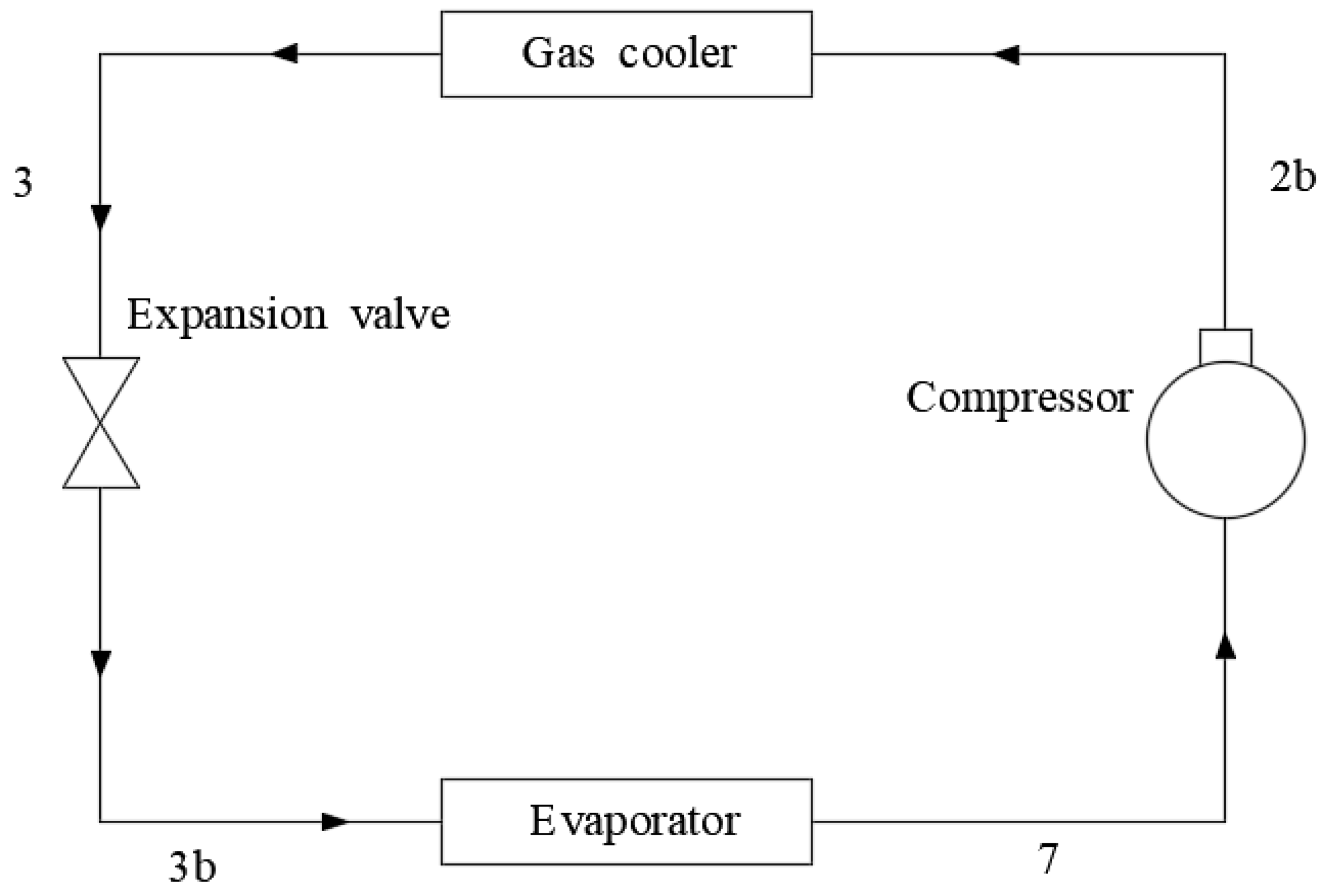
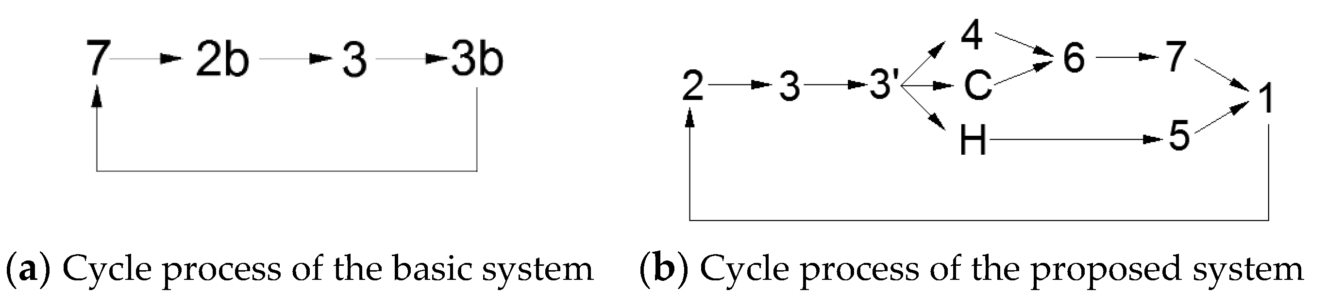
2.1. CO2 Transcritical Refrigeration System with an Expansion Valve (i.e., a Basic System)

In traditional CO2 transcritical refrigeration systems, one expansion valve is used, as shown in Figure 1. From Figure 1, it can be seen that high-pressure and high-temperature CO2 is discharged from the compressor (state 2b), and after a nonphase change heat release process (state 2b to state 3) via a gas cooler, CO2 enters the expansion valve and is expanded from a supercritical state to a vapor–liquid two-phase state (state 3b). Then, it enters the evaporator to absorb heat. Finally, CO2 returns to the compressor.

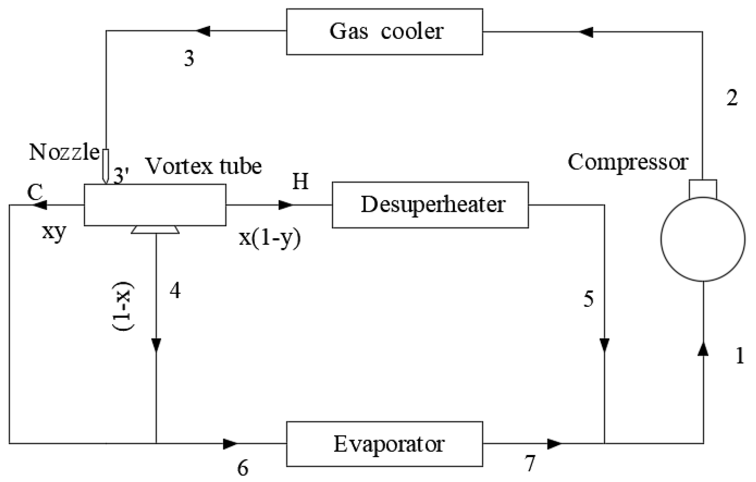
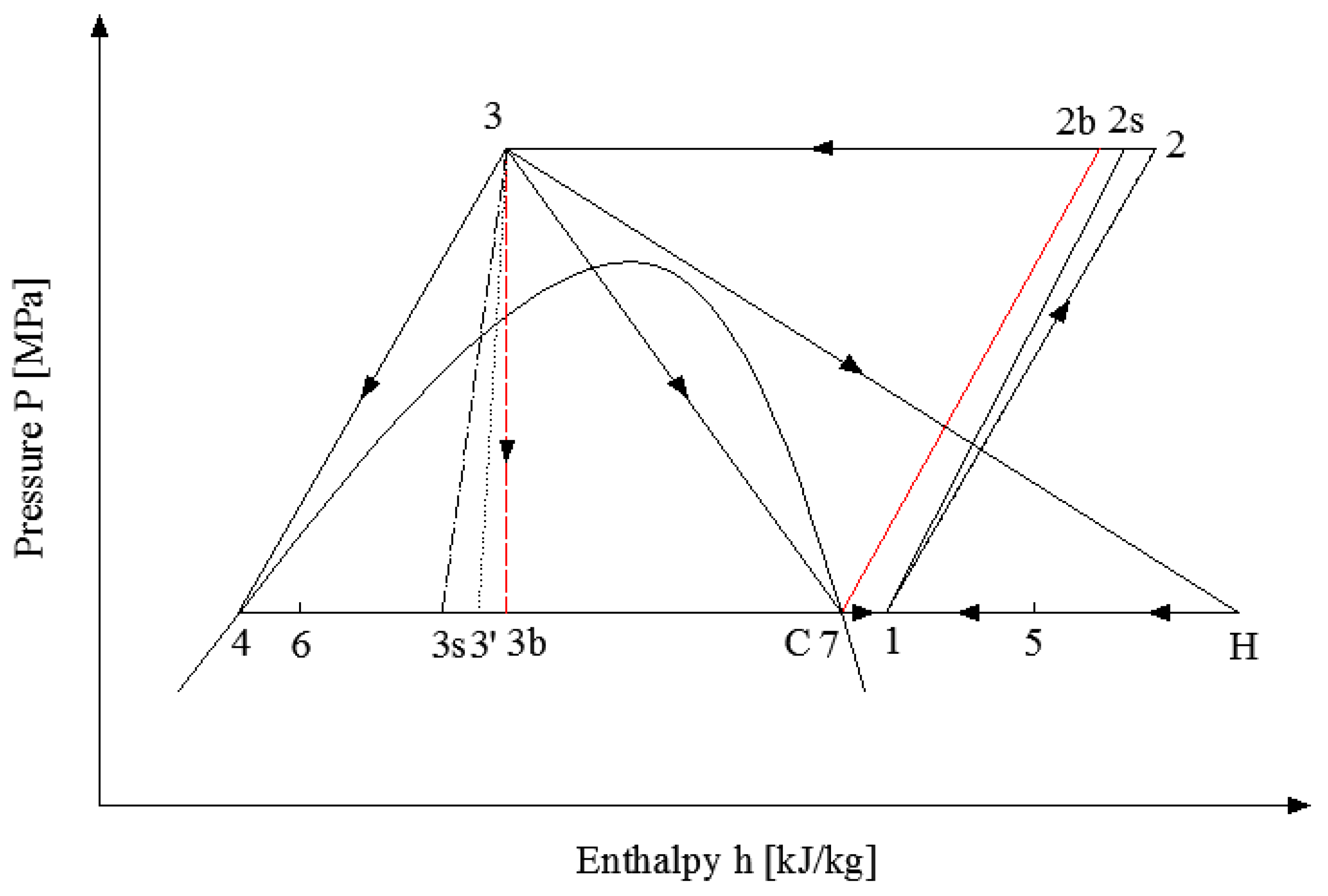
2.2. CO2 Transcritical Refrigeration System with a Vortex Tube (i.e., the Proposed System)

A conventional vortex tube mainly contains an inlet nozzle, a vortex chamber, a cold-end orifice, a hot-end control valve, and a tube. It converts a gas flow initially homogeneous in temperature into two separate flows of differing temperatures. Due to the expansion of high-pressure CO2 through the vortex tube nozzle into the vapor–liquid two-phase zone, the vortex tube in this paper adds a saturated liquid outlet compared to the conventional vortex tube, as shown in Figure 2. The saturated liquid is collected in a ring inside the vortex tube (100% separation efficiency).
The basic cycle and the proposed cycle of CO2 transcritical refrigeration systems (in a pressure (P)–enthalpy (h) diagram) are shown in Figure 3, and each state point code corresponds to the states of systems in Figure 1 and Figure 2. In Figure 3, states 2s and 3s indicate the states when the compression process and the expansion process are isentropic processes, respectively.
From Figure 2 and Figure 3, it can be seen that CO2 is expanded from discharge pressure P (i.e., the gas cooler outlet pressure) to evaporation pressure Pe and divided into three fractions, including saturated liquid (state 4), which is collected by a groove inside the vortex tube; saturated vapor (state C); and superheated gas (state H). The saturated liquid and saturated vapor are mixed again (state 6) and go through the evaporator to give a useful cooling effect. The superheated gas is cooled in the desuperheater to state 5 and then mixed with the gas from the evaporator (state 7) to be state 1 before entering the compressor.
The cycle processes of a basic CO2 transcritical refrigeration system and the proposed system can also be described as shown in Figure 4.
It can be seen from Figure 3 that the enthalpy of the outlet of the vortex tube nozzle (state 3′) is lower than that of the expansion valve outlet (state 3b), and state 3′ is closer to the isentropic state 3s than state 3b. This is due to the higher isentropic effect of the vortex tube nozzle, which reduces the irreversible loss of the CO2 transcritical refrigeration cycle. At the same time, the superheated gas CO2 (state H) separated by the vortex tube is cooled by the desuperheater (state 5) to further reduce the suction temperature of the compressor and improve the system performance COP.

2.3. Mathematical Models and Assumptions

The coefficient of performance of a refrigeration system is the ratio of the cooling capacity provided over the input power of the compressor. According to Figure 3, the calculation of COPb for a basic system with an expansion valve is the following:
COP b = ( h 7 h 3 b ) ( h 2 b h 7 ) .
The vortex tube nozzle outlet enthalpy h3′ at given nozzle efficiency ηn can be calculated by
h 3 = h 3 η n × ( h 3 h 3 s ) .
Then, the vapor quality is found (x = x (Pe, h3′)) by using the thermodynamic property code in Refprop [16].
The definition of the cold mass fraction y can be calculated by
y = m C m H + m C .
Assuming that the refrigerant mass flow rate entering the vortex tube is 1 kg/s, and the liquid (1 − x) kg is separated from the vortex tube, then the total mass flow rate from the cold end at state C and from the hot end at state H is x, i.e.,
m H + m C = x .
Solving Equations (3) and (4), the fraction of saturated vapor is separated as saturated gas at the cold end, mC = x × y, and the rest absorbs all the kinetic energies and is separated as superheated gas at the hot end: mH = x × (1 − y), as shown in Figure 2. Based on the first law of thermodynamics, the enthalpy of the superheated gas hH is given by
h H = h 3 ( 1 x ) × h 4 x × y × h C x × ( 1 y ) .
State 6 is the mixing point of state 4 and state C, so h6 can be found by
h 6 = ( 1 x ) × h 4 + x × y × h 7 ( 1 x + x × y ) .
State 5 can be found by using the effectiveness of desuperheater ε,
t 5 = t H ε × ( t H t w i ) .
State 1 is the mixing point of state 5 and state 7, so enthalpy at state 1 is found by
h 1 = x × ( 1 y ) × h 5 + ( 1 x + x × y ) × h 7 .
For given compressor efficiency and compressor discharge pressure P, enthalpy at state 2 can be found by
h 2 = h 1 + η c × ( h 2 s h 1 ) .
Based on the above calculation, the COPv of the proposed system is obtained by
COP v = ( 1 x + x × y ) × ( h 7 h 6 ) h 2 h 1 .
The code “Imcop” is utilized to describe the COP improvement of the proposed system over the basic system, and it is calculated using the following equation,
Imcop = (COPv − COPb) × 100%/COPb.
The following assumptions are made to simulate the system’s performance:
  • The heat transfer effectiveness of the desuperheater is 0.8;
  • The CO2 compressor isentropic efficiency is 0.8.
The vortex tube characteristics that influence the COP include the vortex tube isentropic efficiency ηn and the cold mass fraction y. The main thermodynamic parameters that influence the COP include the vortex tube inlet temperature T3 (i.e., the gas cooler outlet temperature), the discharge pressure P, the water inlet temperature of the desuperheater Twi, and the evaporation temperature T6. The setting of these parameters is shown in Table 1. The reference values also mean the typical values of the variables. In the following simulation, when the impact of one variable is simulated, the other variables are reference values.
All thermophysical properties of the refrigerant were calculated using the Refprop database [16].

3. Results and Discussions

3.1. Effects of Vortex Tube Characteristics and Thermodynamic Parameters on COP Improvement
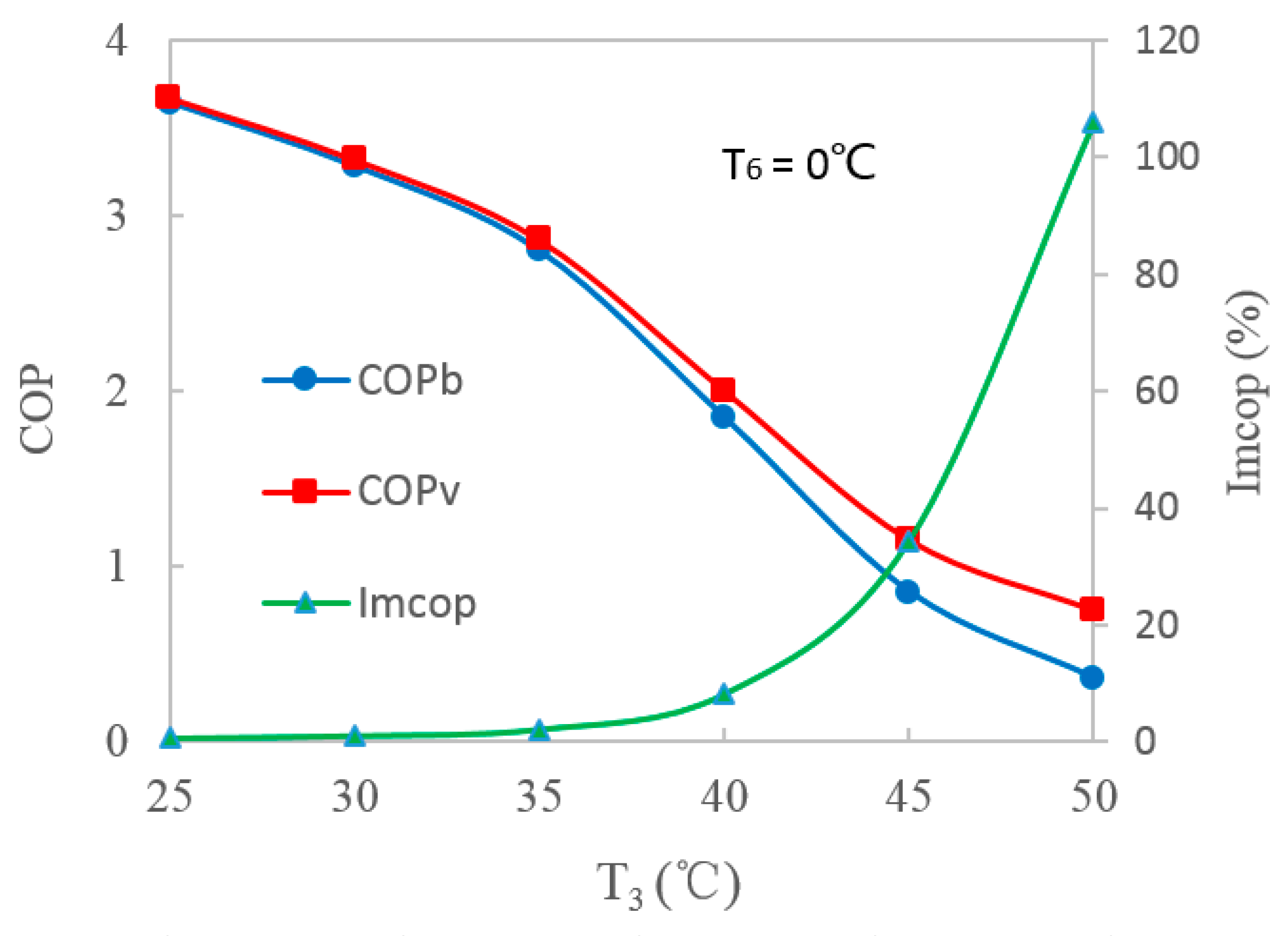
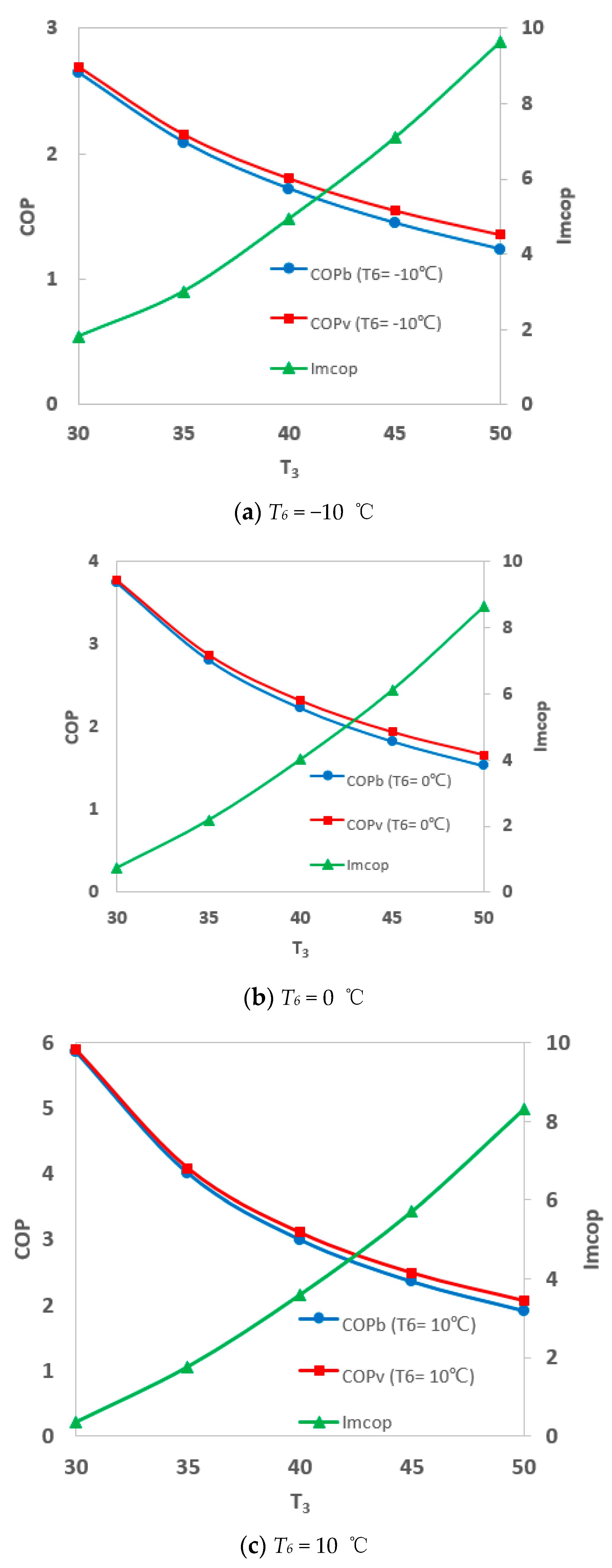
3.1.1. Results

Figure 5 shows the variation in the COPs of the two systems and the COP improvement (i.e., Imcop) of the proposed system with the vortex tube inlet temperature.
From Figure 5, it can be seen that the COP of the basic system and the proposed system decreased with an increase in vortex tube inlet temperature. However, COP improvement increased significantly, especially when the vortex tube inlet temperature T3 was higher than 40 °C. When T3 was 45 °C, the COP of the basic system was 0.86, and the COP of the proposed system was 1.15. Therefore, the COP improvement was 33.7%. The reason was that when the vortex tube inlet temperature was higher, the quality of the CO2 at the outlet of the vortex tube was higher, which caused a more efficient energy separation effect by the vortex tube and benefited COP improvement.
Figure 6 shows the variation in COPs and COP improvement with evaporation temperature T6. It can be seen that COP improvement increased gradually with a decrease in evaporation temperature. When the evaporation temperature was −5 °C, the COP increased from 1.61 to 1.76, and the COP improvement was 9.3%. The reason was that the quality of the CO2 from the nozzle of the vortex tube (state point 3’) increased when the evaporation temperature decreased, and then more CO2 hot gas (state H) entered the desuperheater and was cooled, which led to a lower enthalpy of CO2 (state 1) before entering the compressor. So, the input power of the compressor decreased and caused a higher COP.
The isentropic efficiency of a vortex tube changes with different vortex tube geometries. In order to design a vortex tube, it is necessary to investigate the impact of the isentropic efficiency of a vortex tube on a system’s COP. Figure 7 shows the variation in COPs and COP improvement with vortex tube isentropic efficiency. It can be seen that COP improvement increased obviously with an increase in the vortex tube isentropic efficiency ηn. COP improvement was 11.6% when the expansion in the vortex tube was an isentropic process. Therefore, increasing vortex tube isentropic efficiency was an important way to improve COP, too.
Figure 8 shows the variation in COPs and COP improvement with cold mass fraction. It can be seen that COPv gradually increased with an increase in cold mass fraction y. When the cold mass fraction y was 0.8, the COP of the proposed system was 11.5% higher than that of the basic system. When the cold mass fraction y increased, the hot gas (state H) temperature increased, and heat capacity was rejected from the desuperheater increases, too. Therefore, the temperature and enthalpy of CO2 at the inlet of compress (state 1) decreased, which benefited COP improvement.
Similarly, when the inlet water temperature of the desuperheater decreased, COP improvement increased due to more heat rejection. When Twi was 10 °C, COP improvement was 12.0%, as shown in Figure 9.
Figure 10 shows the variation in COPs and COP improvement with discharge pressure. It can be seen that the COPs of both the basic system and the proposed system increased and then decreased with discharge pressure increases, and there were optimal discharge pressures with maximum cooling COPs for the two systems. However, COP improvement decreased significantly with discharge pressure increases, especially when the discharge pressure was lower than 9 MPa. When the discharge pressure was 8.4 MPa, COP improvement increased by 25.3%.

3.1.2. Discussions

From the above results, it can be found that the discharge pressure was a critical thermodynamic parameter for COP improvement. Therefore, it was extremely important and necessary to research the optimal discharge pressure for the optimal design of the proposed CO2 transcritical refrigeration system with a vortex tube. Therefore, research on the optimal pressure correlation for the proposed system, and its effects on COPs and COP improvement, is developed in the following sections.

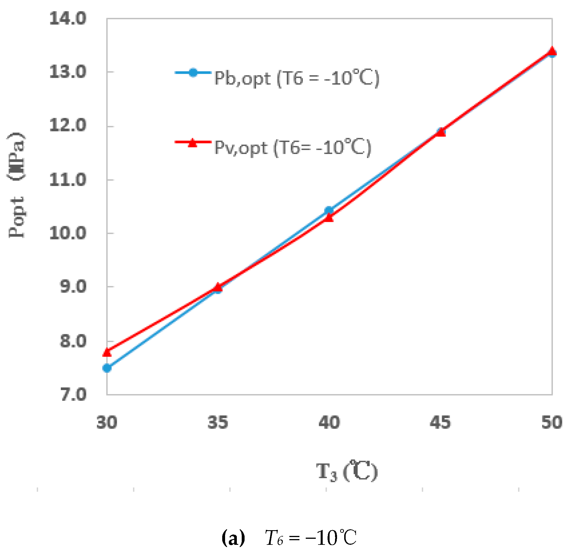
3.2. Regression of Optimal Discharge Pressure Correlation for the Proposed System with a Vortex Tube and a COP Improvement Investigation under Optimal Discharge Pressure

As is known, due to the particular characteristics of CO2 transcritical refrigeration cycles, there is an optimal discharge pressure under which the COP is at a maximum. For a basic system, the optimal discharge pressure correlation has already been researched and given. It is a function of the gas cooler outlet temperature and the evaporation temperature, and it can be described as the following [15]:
Pb,opt = (2.778 − 0.0157 × T6) T3 + (0.381T6 − 9.34).
Similarly, there is also an optimal discharge pressure for the proposed system with a vortex tube. Because the proposed system is more complex than the basic system, the influence factors include not only the vortex tube inlet temperature T3 and the evaporation temperature T6, but also the characteristic parameters of the vortex tube, such as cold mass fraction y, vortex tube isentropic efficiency ηn, and water inlet temperature of the desuperheater Twi. Thus, the optimal discharge pressure is the function Pv,opt = ƒ(T3,T6,y,ηn,Twi).
In order to simplify the correlation, some of the parameters are given as the following assumptions:
  • The cold mass fraction y is 0.5;
  • The vortex tube isentropic efficiency ηn is 0.8;
  • The water inlet temperature of the desuperheater Twi is 25 °C.
Based on the mathematical models in Section 2, the optimal discharge pressures were calculated for the proposed system under different inlet temperatures of the vortex tube and evaporation temperatures, and the optimal discharge pressures of the basic system were also calculated, as shown in Figure 11. From Figure 11, it can be seen that there were slightly differences between the optimal discharge pressure values for the proposed system and the basic system. Therefore, the vortex tube did not much affect the values of the optimal discharge pressure.
Based on the simulation results, the values of the optimal discharge pressure for the proposed CO2 transcritical refrigeration system with a vortex tube were regressed in terms of vortex tube inlet temperature and evaporation temperature, and the correlation was obtained as the following:
Pv,opt = 2.4895 − 0.027T6 + 0.0985T3 + 0.00229T32.
Apart from the conditions (y = 0.5, ηn = 0.8, Twi = 25 °C) set for this correlation, a range in the vortex tube inlet temperature T3 from 30 °C to 50 °C and the evaporation temperature T6 from −10 °C to 10 °C was also required. It is worth mentioning that the coefficient of determination R2 was 99.8%, and the average deviation was less than 5%, which indicated that the relationship between the discharge pressure Pv,opt, vortex tube inlet temperature T3, and evaporation temperature T6 were highly positively correlated. Moreover, the value of the F significant statistic was 2.75 × 10⁻¹⁵, which was far less than the significance level of 0.05, showing a significant regression effect of this regression equation.
According to Equations (12) and (13), the optimal discharge pressures of the basic system and the proposed system could be calculated with various T3 and T6. Then, based on the above mathematical models, the COPs and COP improvement were obtained, as shown in Figure 12.
From Figure 12, it can be seen that the COPs of the proposed system were higher than those of the basic system. COP improvement increased gradually with an increase in the vortex tube inlet temperature T3 and decreased slightly with an increase in the evaporation temperature T6. It should be noted that COP improvement increased obviously when the vortex tube inlet temperature T3 was higher than 40 °C. When the vortex tube inlet temperature T3 was −10 °C and the evaporation temperature T6 was 45 °C, COP improvement was 7.1%.
Based on the above results, when the gas cooler outlet temperature is high, utilizing a vortex tube in a CO2 transcritical refrigeration system can be more beneficial in terms of reducing irreversible loss and improving the COP.

4. Conclusions

A CO2 transcritical refrigeration system with a vortex tube expansion was proposed in this paper. In the proposed system, one vortex tube is used to replace the expansion valve in order to reduce irreversible loss and improve system performance COP. The influences of various parameters on the COP improvement of the proposed system were simulated and analyzed. The optimal discharge pressure correlation of the proposed CO2 transcritical refrigeration system with a vortex tube was regressed and obtained. The following conclusions were drawn:
  • The COP of the proposed system with a vortex tube was higher than that of the basic system with an expansion valve;
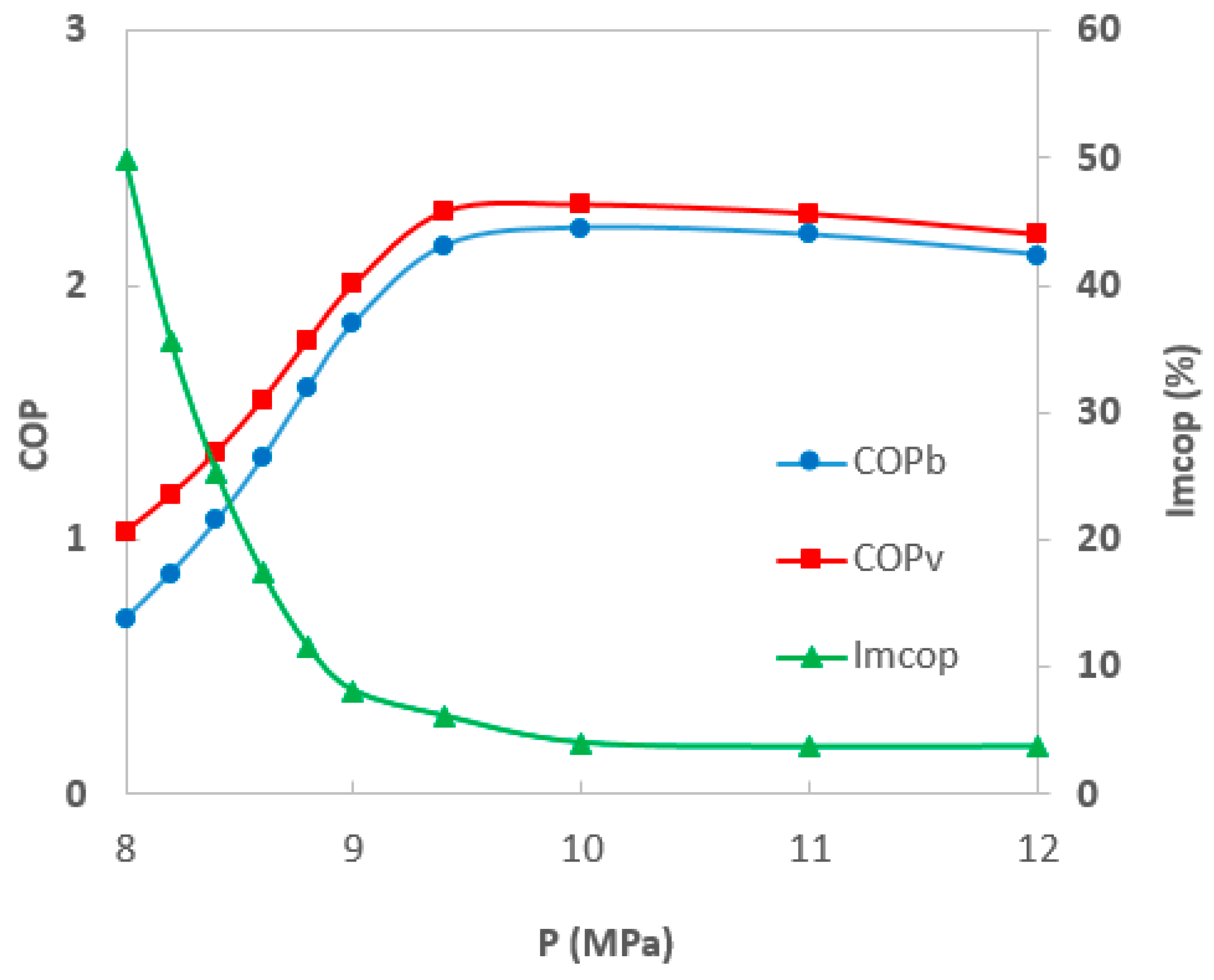
  • The critical influence factors of COP improvement were the inlet temperature of the vortex tube (i.e., the outlet temperature of the gas cooler) and the discharge pressure. The higher the inlet temperature of the vortex tube, the higher COP improvement was. The lower the discharge pressure, the higher COP improvement was. When the inlet temperature of the vortex tube was 45 °C, the discharge pressure was 9 MPa, and the COP increased by 33.7%;
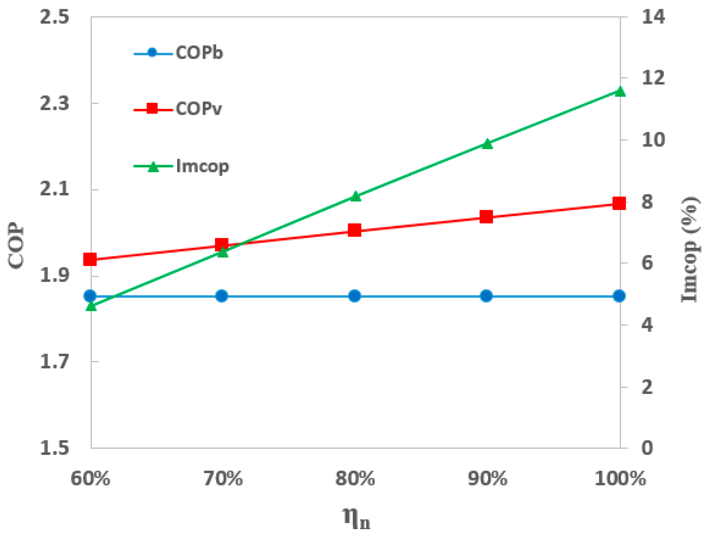
  • The higher the isentropic efficiency of the vortex tube, the higher the COP improvement was. COP improvement could be up to 11.6%;
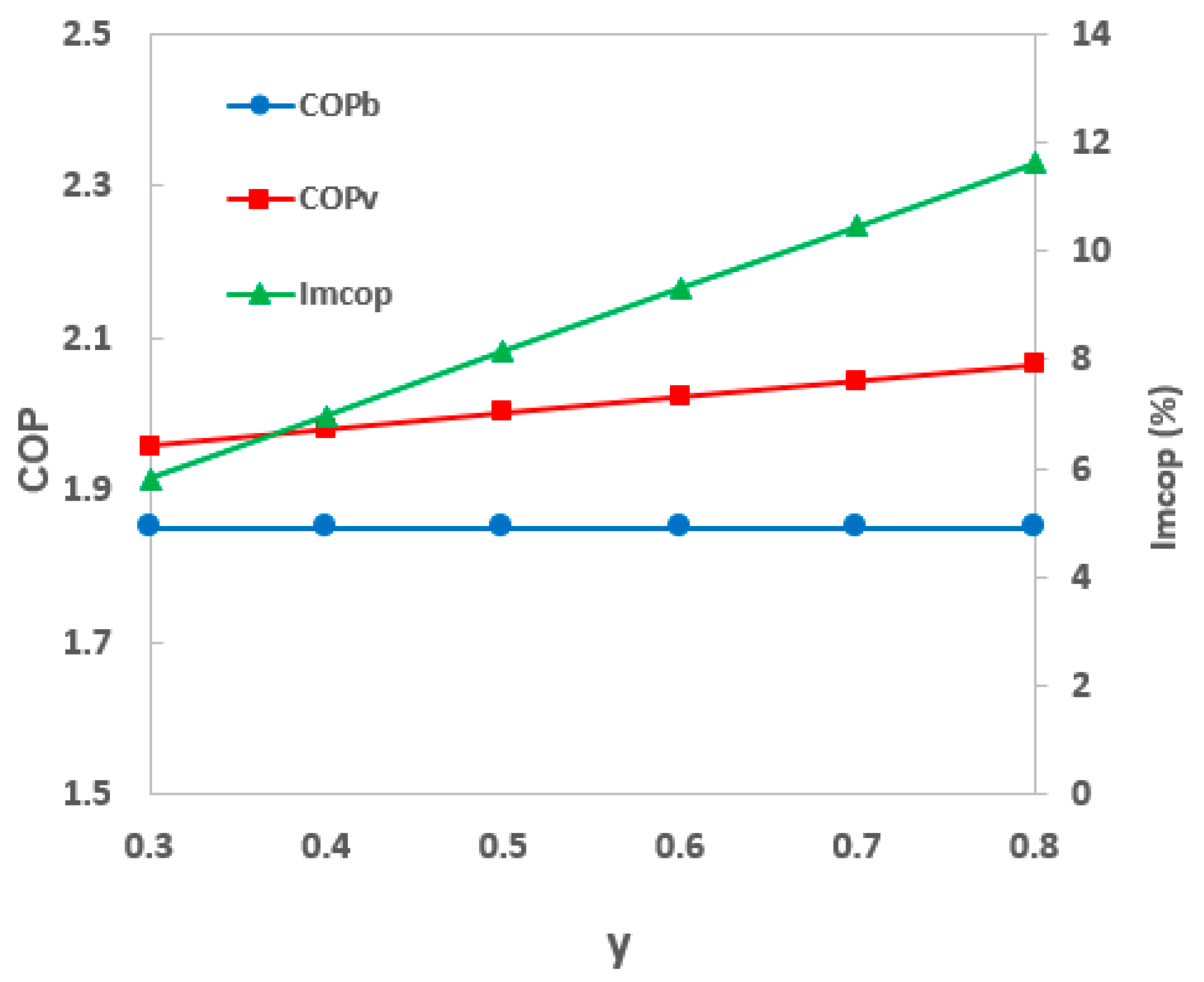
  • The more the cold mass fraction of the vortex tube, the higher the COP improvement was. When the cold mass fraction was 0.8, COP improvement was 11.5%;
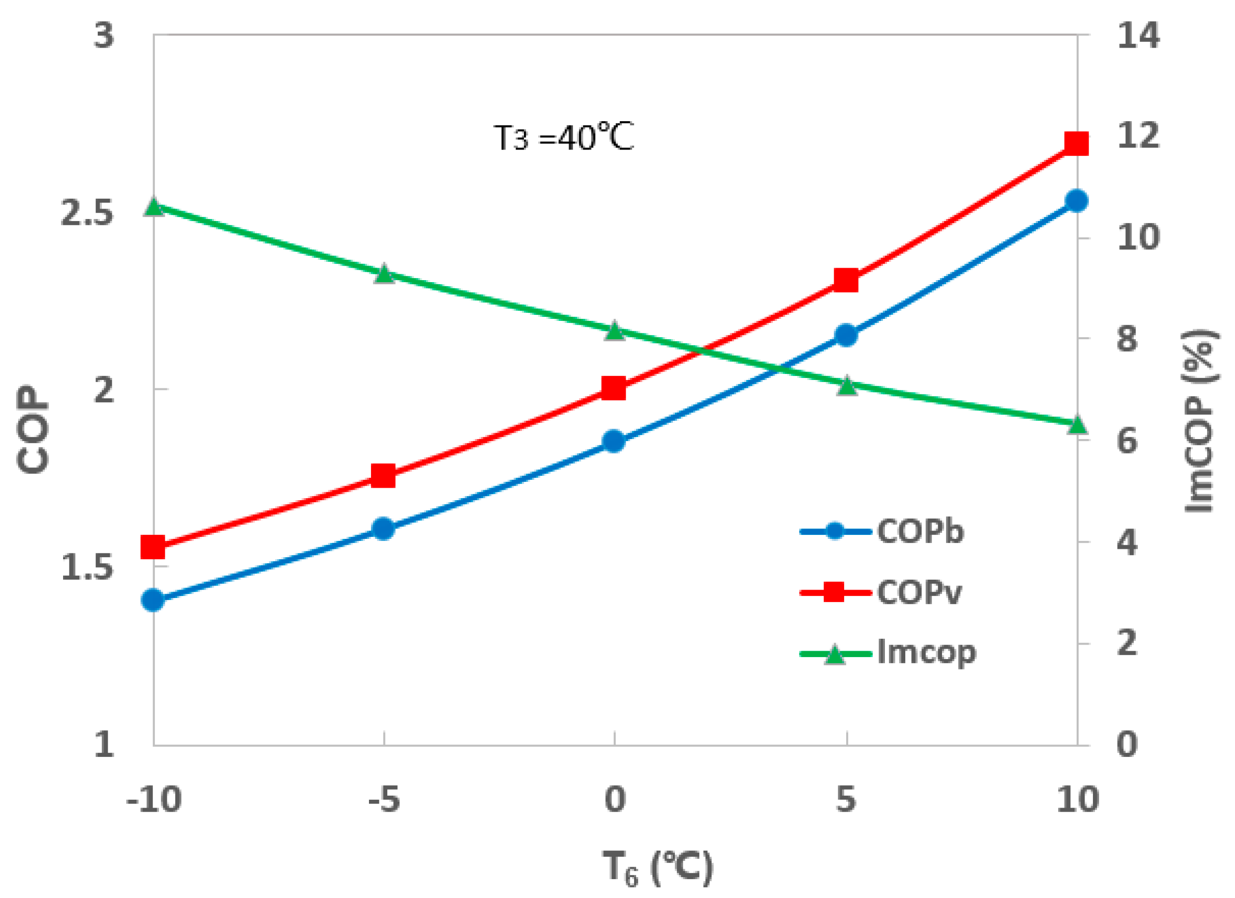
  • The lower the evaporation temperature, the higher COP improvement was. When the evaporation temperature was −5 °C, COP improvement was 9.2%;
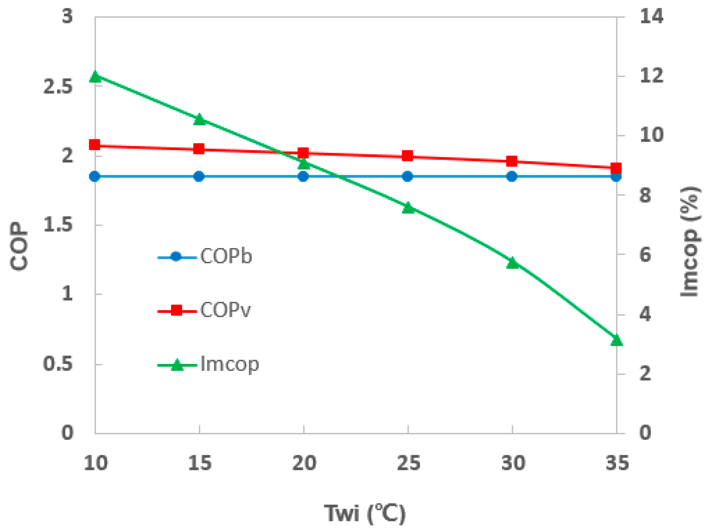
  • The lower the inlet water temperature of the desuperheater, the higher COP improvement was. When the inlet water temperature of the desuperheater was 10 °C, COP improvement was 12.0%;
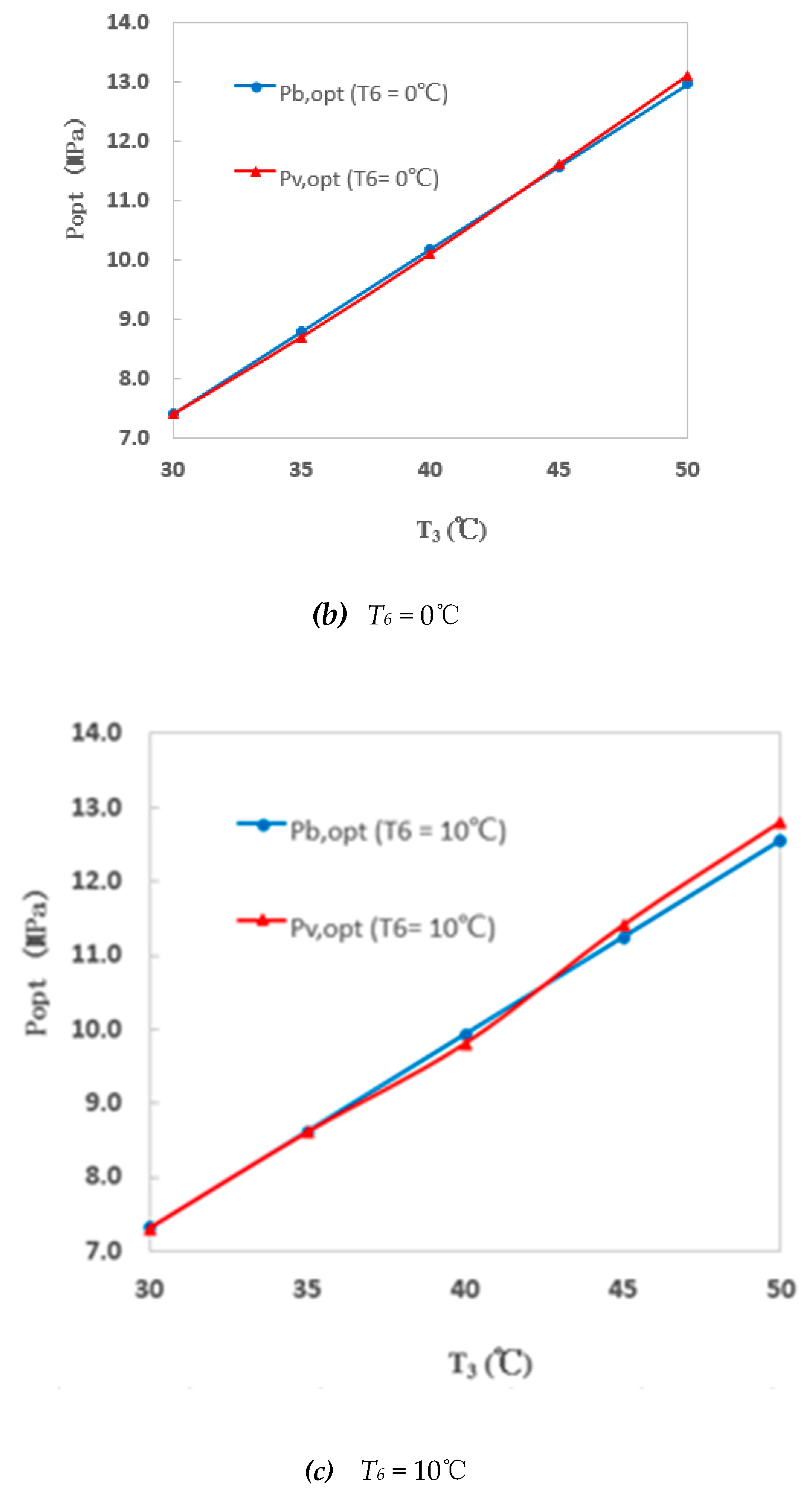
  • Under optimal discharge pressures, COP improvement increased gradually with an increase in vortex tube inlet temperature and decreased slightly with an increase in evaporation temperature. When the vortex tube inlet temperature was −10 °C, and the evaporation temperature was 45 °C, COP improvement was 7.1%.
The effects of the vortex tube inlet temperature and discharge pressure on COP improvement were more significant compared to the isentropic efficiency, evaporation temperature, desuperheater water inlet temperature, and cold mass fraction of the vortex tube in the proposed system. Therefore, the application of a vortex tube is highly recommended when a higher vortex tube inlet temperature and lower discharge pressure are required.
These research results provide a theoretical basis for the following design and experimental research of a CO2 transcritical refrigeration system with a vortex tube.

Author Contributions

Funding acquisition, Y.L.; investigation, Y.S. and D.T.; methodology, Y.L.; validation, Y.S.; writing—original draft, Y.S.; writing—review and editing, Y.L.

Funding

This research was funded by Shanghai Committee of Science and Technology of China, grant number 17PJ1407200.

Acknowledgments

The authors gratefully acknowledge the Shanghai Committee of Science and Technology of China (Shanghai Pujiang Program, grant number 17PJ1407200).

Conflicts of Interest

The authors declare no conflicts of interest.

Nomenclature

English letters
COPcoefficient of performance
COPbCOP of the basic system
COPvCOP of the proposed system
hspecific enthalpy (kJ/kg)
ImcopCOP improvement of the proposed system over the basic system (%)
Pdischarge pressure (MPa)
Ttemperature (°C)
xquality
ycold mass fraction
mmass flow rate (kg/s)
Greek letters
εheat exchanger effectiveness
ηisentropic efficiency
Subscript
bbasic system with expansion valve
ccompressor or cold end of vortex tube
Hhot end of vortex tube
sisentropic process
nvortex tube nozzle
wiwater inlet of desuperheater
vthe proposed system with vortex tube expansion
optoptimal

References

  1. Maina, P.; Huan, Z. A review of carbon dioxide as a refrigerant in refrigeration technology. S. Afr. J. Sci. 2015, 111. [Google Scholar] [CrossRef]
  2. Sawalha, S.; Karampour, M.; Rogstam, J. Field measurements of supermarket refrigeration systems. Part I: Analysis of CO2 trans-critical refrigeration systems. Appl. Therm. Eng. 2015, 87, 633–647. [Google Scholar] [CrossRef]
  3. Robinson, D.M.; Groll, E.A. Efficiencies of CO2 trans-critical cycles with and without an expansion turbine. Int. J. Refrig. 1998, 21, 577–589. [Google Scholar] [CrossRef]
  4. Li, D.; Back, J.S.; Groll, E.; Lawless, P.B. Thermodynamic analysis of vortex tube and work output expansion devices for the CO2 trans-critical cycle. In Proceedings of the Fourth IIR-Gustav Lorentzen Conference on Natural Working Fluids at Purdue, Lafayette, IN, USA, 25–28 July 2000; pp. 433–440. [Google Scholar]
  5. Groll, E.A.; Kim, J.-H. Review Article: Review of recent advances toward CO2 trans-critical cycle technology. HVAC R Res. 2007, 13, 499–520. [Google Scholar] [CrossRef]
  6. Bodys, J.; Smolka, J.; Banasiak, K.; Palacz, M.; Haida, M.; Nowak, A.J. Performance improvement of the R744 two-phase ejector with an implemented suction nozzle bypass. Int. J. Refrig. 2018, 90, 216–228. [Google Scholar] [CrossRef]
  7. Sawalha, S.; Piscopiello, S.; Karampour, M.; Manickam, L.; Rogstam, J. Field measurements of supermarket refrigeration systems. Part II: Analysis of HFC refrigeration systems and comparison to CO2 trans-critical. Appl. Therm. Eng. 2017, 111, 170–182. [Google Scholar] [CrossRef]
  8. Yamaguchi, H.; Zhang, X.R. A novel CO2 refrigeration system achieved by CO2 solid–gas two-phase fluid and its basic study on system performance. Int. J. Refrig. 2009, 32, 1683–1693. [Google Scholar] [CrossRef]
  9. Shamsoddini, R.; Khorasani, A.F. A new approach to study and optimize cooling performance of a Ranque–Hilsch vortex tube. Int. J. Refrig. 2012, 35, 2339–2348. [Google Scholar] [CrossRef]
  10. Kandil, H.A.; Abdelghany, S.T. Computational investigation of different effects on the performance of the Ranque–Hilsch vortex tube. Energy 2015, 84, 207–218. [Google Scholar] [CrossRef]
  11. Chen, J.; Zeng, R.; Zhang, W.; Qiu, L.; Zhang, X. Numerical analysis of energy separation in Ranque-Hilsch vortex tube with gaseous hydrogen using real gas model. Appl. Therm. Eng. 2018, 140, 287–294. [Google Scholar] [CrossRef]
  12. Chang, S.W.; Yu, K.C. Thermal performance of reciprocating two-phase thermo-syphon with nozzle. Int. J. Therm. Sci. 2018, 129, 14–28. [Google Scholar] [CrossRef]
  13. Han, X.; Li, N.; Wu, K.; Zhang, Z.; Tang, L.; Chen, G.; Xu, X. The influence of working gas characteristics on energy separation of vortex tube. Appl. Therm. Eng. 2013, 61, 171–177. [Google Scholar] [CrossRef]
  14. Manimaran, R.; Lund, H.; Kaiser, M.J. Computational analysis of energy separation in a counter-flow vortex tube based on inlet shape and aspect ratio. Energy 2016, 107, 17–28. [Google Scholar] [CrossRef]
  15. Liao, S.M.; Zhao, T.S.; Jakobsen, A. A correlation of optimal heat rejection pressures in CO2 trans-critical cycles. Appl. Therm. Eng. 2000, 20, 831–841. [Google Scholar] [CrossRef]
  16. Lemmon, E.W.; Huber, M.L.; McLinden, M.O. REFPROP, NIST Standard Reference Database 23, v.9.1; National Institute of Standards: Gaithersburg, MD, USA, 2013.
Figure 1. Schematic of a basic CO2 transcritical refrigeration system with an expansion valve.
Sustainability 11 02021 g001
Figure 2. Schematic of the proposed CO2 transcritical refrigeration system with a vortex tube.
Sustainability 11 02021 g002
Figure 3. Pressure (P)–enthalpy (h) diagram of the proposed cycle and the basic cycle.
Sustainability 11 02021 g003
Figure 4. Cycle processes of the basic system and the proposed system: (a) Cycle process of the basic system; (b) Cycle process of the proposed system.
Sustainability 11 02021 g004
Figure 5. Variations in coefficients of performance (COPs) and COP improvement with vortex tube inlet temperature T3.
Sustainability 11 02021 g005
Figure 6. Variation in COPs and COP improvement with evaporation temperature T6.
Sustainability 11 02021 g006
Figure 7. Variation in COPs and COP improvement with vortex tube isentropic efficiency ηn.
Sustainability 11 02021 g007
Figure 8. Variation in COPs and COP improvement with cold mass fraction y.
Sustainability 11 02021 g008
Figure 9. Variation in COPs and COP improvement with inlet water temperature of the desuperheater Twi.
Sustainability 11 02021 g009
Figure 10. Variation in COPs and COP improvement with discharge pressure P.
Sustainability 11 02021 g010
Figure 11. Variation in optimal discharge pressures with the inlet temperature of the vortex tube/expansion valve T3 and evaporation temperature T6 for the proposed system and the basic system: (a) T6 = −10 °C, (b) T6 = 0 °C, (c) T6 = 10 °C.
Sustainability 11 02021 g011aSustainability 11 02021 g011b
Figure 12. Variation in COPs and COP improvement under an optimal discharge pressure with an inlet temperature of the vortex tube/expansion valve T3 and evaporation temperature T6.
Sustainability 11 02021 g012
Table 1. Parameter settings for the performance simulation.
ParametersReference ValueVariation Range
Vortex tube inlet temperature T3, °C4025–45
Evaporation temperature T6, °C0−10–10
Vortex tube isentropic efficiency ηn80%0%–100%
Cold mass fraction y0.50.3–0.8
Water inlet temperature of the desuperheater Twi, °C2510–35
Discharge pressure P, MPa98–12

