Abstract
To maximize the direct insolation received by flat-plate photovoltaic (PV) modules, the tilt angle is usually the site’s latitude and the modules are oriented towards the equator. However, this may not be the optimal placement, as the local climatic conditions will influence the optimal orientation and tilt angle. Transposition models can be used to simulate the insolation on planes with various tilts and azimuths, using a single set of (horizontal) global and diffuse irradiance measurements. Following this method, five maps including optimal orientations, tilt angles, maximum annual tilted irradiations, percentage improvements of the optimally-tilted PV installation versus the conventional latitude-tilted PV installation, and annual diffuse fraction were plotted over the geographical area of Japan. Spatial patterns in these maps were observed and analyzed. The key contribution of this work is to establish a database of optimal PV installations in Japan. Compared to the conventional rule of thumb of tilting the module at latitude facing south, it is shown that the optimally tilted surface receives up to 2% additional annual solar irradiation.
1. Introduction
After the Fukushima nuclear disaster in 2011, the Japanese government announced plans to expand the solar photovoltaic (PV) installations to reduce reliance on nuclear power. Following the implementation of Japan’s renewable energy feed-in-tariff (FIT) scheme in July 2012, photovoltaic (PV) installation has grown rapidly [1]. In this paper, the optimal orientation and tilt angle for maximizing in-plane solar irradiation in Japan was studied to understand the potential of PV adoption in Japan.
The orientation (azimuthal rotation) and tilt angle for fixed array installation are critical parameters that affect a photovoltaic (PV) system performance, directly determining the solar radiation received by the PV modules. Various studies have been carried out to determine the optimal orientation and tilt for different locations [2,3,4,5,6,7,8]. Khoo et al. studied the optimal orientation and tilt angle for maximizing in-plane solar irradiation for fixed-tilt PV modules in Singapore [8]. Using the methodology from previous work and the publicly available countrywide weather data in Japan, this paper presents a visual database of optimal orientation and tilt angles in Japan and correlates it to local climatic conditions such as irradiation intensity and diffuse fraction.
2. Materials and Methods
This section briefly describes the data set used, the model used for the transposition, and method of determining the optimal orientation and tilt angle.
2.1. Data Collection
The global horizontal irradiance (GHI) and diffuse horizontal irradiance (DHI) are the required inputs for determining the optimal orientation and tilt angle. GHI and DHI for locations across Japan were obtained from Japan’s New Energy and Industrial Technology Development Organization (NEDO), using meteorological test data for photovoltaic systems (METPV-11) [9]. The dataset consists of post-processed hourly meteorological data for a 1-year period (similar to a typical meteorological year dataset) at 837 locations extracted from ground measurements spanning 20 years (1990–2009). Similar to typical meteorological year (TMY3) data from the National Solar Radiation Data Base (NSRDB), METPV11 data accurately represent the long-term solar resource distribution across Japan. To promote ease of use of the data for different sites in Japan, NEDO provides a user-friendly web interface app [10]. The locations covered in this study are shown in Figure 1, whereby each colored pixel denotes a station, with the color indicating the annual solar irradiation.
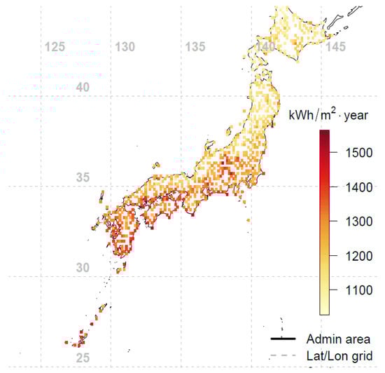
Figure 1.
Geographic locations of the 837 weather stations in Japan used for this study. Each colored pixel denotes a station, while the color indicates the annual global horizontal irradiation value in kWh/m2.
2.2. Transposition Model to Convert Horizontal Irradiance to Tilted Irradiance
To determine the optimal orientation and tilt angle of a flat-plate PV module, first we converted the GHI and DHI into tilted irradiance using a transposition model. The direct beam radiation on a tilted surface can be calculated using geometric relations, whereas the conversion for the diffuse radiation is more complex and has been approached using different models, for example Liu and Jordan [11], Klucher [12], Hay and Davies [13], and Perez et al. [14], etc. For this study, the Perez et al. transposition model is used due to its proven accuracy [8,15,16,17,18,19,20,21].
The Perez et al. model [14] is an empirical model based on a detailed statistical analysis of the sky’s diffuse components. The model breaks the diffuse irradiance into the three components of isotropic background, circumsolar and horizon zone:
where Id,tilt is the total tilted diffuse irradiance, β the tilt angle, θ is the angle of incidence, and θz the zenith angle; F1 and F2 are complex empirically fitted functions to describe circumsolar and horizon brightness [14].
2.3. Determining the Optimal Orientation and Tilt Angle
For each location, the hourly GHI and DHI data over the 1-year period were used as an input to the Perez et al. transposition model to calculate the hourly tilted irradiance for all possible orientations (0° to 360°) and tilt angles (0° to 90°). The hourly tilted irradiance was summed to get the annual tilted irradiation for the different orientations and tilt angles. The results are then represented as a polar contour plot, as can be seen in Figure 2, using Tokyo city as an example. For Tokyo (35.69° N, 139.76° E), a maximum annual tilted irradiation of 1847 kWh/m2 is achievable through a surface oriented around 179° SE with a tilt angle of 35°. Extending the same methodology across 837 locations in Japan, the optimal orientation and tilt angle that yield the highest annual tilted irradiation were then determined, see Figure 3, Figure 4 and Figure 5.
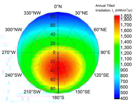
Figure 2.
Polar contour plot of annual tilted irradiation for different tilts and orientations in Tokyo, Japan. A surface facing 179° SE with a tilt angle of around 35° receives the highest annual irradiation of 1847 kWh/m2, shown as the ‘x’ in the polar contour plot.
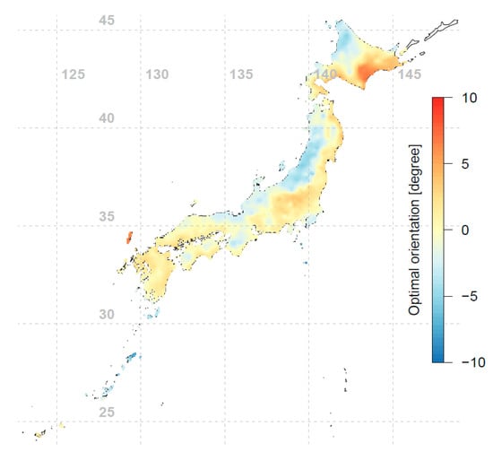
Figure 3.
Optimal orientations for fixed-tilt PV modules in Japan (interpolated using 837 data points). The results are represented as the deviations from the south orientation. A negative (positive) angle means that the module faces slightly eastwards (westwards).
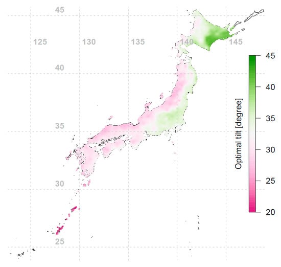
Figure 4.
Optimal tilt angles for fixed-tilt PV installations in Japan (interpolated using 837 data points).
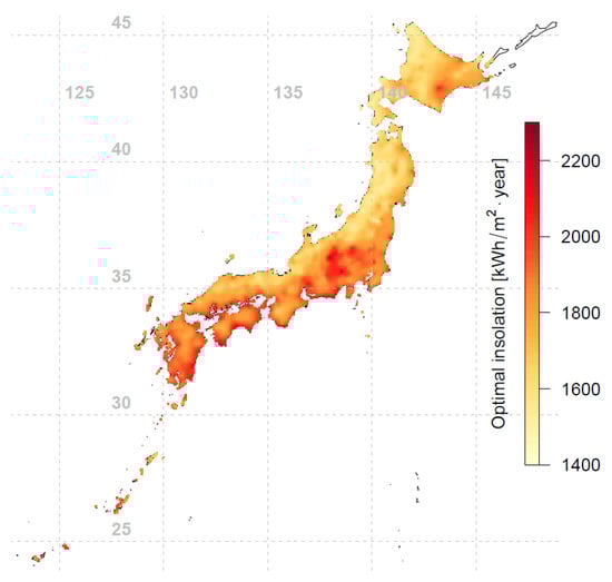
Figure 5.
Optimal annual tilted irradiation for fixed-tilt photovoltaic (PV) modules in Japan (interpolated using 837 data points).
3. Results
Conventional rule of thumb suggests that the PV array should be installed facing the equator and tilted toward the sun’s average elevation, i.e., having a tilt angle equal to the latitude of the array’s location. For Japan, as seen in Figure 3, different locations’ optimal orientations are indeed mostly facing south, within ±10° of true south. However, from Figure 4 we see that the optimal tilt angles for different locations do not necessarily follow the conventional wisdom of using latitude as the tilt angle; the deviation can be up to 15° from the latitude-tilt values. Comparing Figure 1 and Figure 4, an interesting phenomenon is observed: the western side of Japan (which has lower annual irradiation) tends to have lower optimal tilt angles compared to the eastern side of Japan. To further investigate this observation, the annual diffuse fraction for all locations were investigated and plotted in Figure 6. The diffuse fraction is the ratio of diffuse horizontal irradiance (DHI) and global horizontal irradiance (GHI). Figure 6 shows that at a similar latitude, the western side of Japan has a higher annual diffuse fraction compared to the eastern side of Japan. It can be seen that the optimal tilt angle is correlated with annual irradiation and diffuse fraction. Locations with lower annual irradiation are associated with higher precipitation and hence higher annual diffuse fractions (see Figure 6). When the diffuse fraction of the irradiance is high, it is more optimal for the PV module to have a larger viewing area of the sky (i.e., be inclined at a lower tilt angle) to capture a larger proportion of the diffuse irradiance. This effect is also shown in recent studies [22,23]. Comparison of Figure 5 and Figure 6 shows that the locations with a higher annual diffuse fraction tend to have lower annual tilted irradiation, and vice versa.
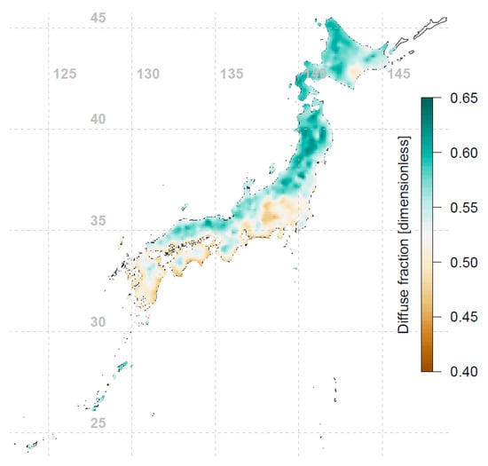
Figure 6.
Annual diffuse fraction map of Japan (interpolated using 837 data points). The diffuse fraction is the ratio of diffuse horizontal irradiance (DHI) and global horizontal irradiance (GHI).
Next, the percentage increase in annual irradiation on a fixed-tilt PV module surface mounted at the optimal orientation and tilt angle compared to a south-facing latitude-tilted PV module was determined (see Figure 7). As can be seen, the increase in annual tilted irradiation for an optimally oriented and tilted PV module is up to 2%. The gain is highest in the northwestern region of Japan. This is because the optimal tilt angles in this region deviate more from latitude, due to the high annual diffuse content.
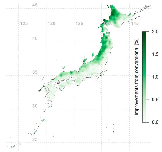
Figure 7.
Percentage increase in annual tilted irradiation on a fixed-tilt PV module surface mounted at optimal orientation and tilt angle compared to a south-facing latitude-tilted PV module (interpolated using 837 data points).
In the real world, the ultimate parameter of interest is the energy output of the PV systems. To accurately calculate the energy output, many loss mechanisms have to be included, as shown in a detailed model by King et al. [24]. To simplify the modeling, the optimal orientation and tilt angle was determined solely from the annual tilted irradiation received by the PV modules. This approach is reasonable because a PV system’s electrical output is proportional to the annual irradiation it receives.
4. Conclusions
METPV-11 provides very comprehensive representative weather conditions across different locations in Japan. Modeling was performed using hourly measured global horizontal irradiance (GHI) and diffuse horizontal irradiance (DHI) from METPV-11 to calculate the hourly tilted irradiance for different orientations and tilt angles for 837 locations in Japan. The flat-plate PV modules’ optimal orientation and tilt angles were then determined by finding the value for which the total radiation on a particular orientation and tilt was the highest. While the optimal tilt angle was found to deviate by up to 15° from the conventional latitude tilt, the increase in annual tilted irradiation for an optimally oriented and tilted PV module is up to 2%. It was also found that annual diffuse fraction plays a major role in determining the optimal tilt angle. For the same latitude, compared to locations with a lower annual diffuse fraction, locations with a higher annual diffuse fraction were found to have a lower optimal tilt angle. It was hypothesized that for locations with a high diffuse fraction, it is more advantageous for PV modules to be tilted at a lower angle, to “see” a larger sky area for capturing the diffuse irradiance.
As there are uncertainties in the data and transposition model, which were not investigated in this study, the percentage gain value presented in this study should only be used as an indication on how to optimally orient and tilt the PV system at the location of interest. For accurate PV system performance modeling, onsite measurements should be carried out.
Author Contributions
All the authors collectively carry out the research and analysis. C.Y. conceived the main idea and led the paper writing with contribution and guidance from Y.S.K. and S.H. C.Y., Y.S.K. and J.C. contributed to the computer simulation, and J.Y. critically revised the manuscript.
Funding
This research was supported by the North China Electric Power University, Solar Energy Research Institute of Singapore (SERIS), and China Three Gorges New Energy Co., Ltd. under China Pingshan 10MW PV system project research grant.
Conflicts of Interest
The authors declare no conflict of interest.
References
- Inoue, M.; Genchi, Y.; Kudoh, Y. Evaluating the Potential of Variable Renewable Energy for a Balanced Isolated Grid: A Japanese Case Study. Sustainability 2017, 9, 119. [Google Scholar] [CrossRef]
- Pourgharibshahi, H.; Abdolzadeh, M.; Fadaeinedjad, R. Verification of Computational Optimum Tilt Angles of a Photovoltaic Module Using an Experimental Photovoltaic System. Environ. Prog. Sustain. Energy 2015, 34, 1156–1165. [Google Scholar] [CrossRef]
- Zang, H.; Guo, M.; Wei, Z.; Sun, G. Determination of the Optimal Tilt Angle of Solar Collectors for Different Climates of China. Sustainability 2016, 8, 654. [Google Scholar] [CrossRef]
- Guo, M.; Zang, H.; Gao, S.; Chen, T.; Xiao, J.; Cheng, L.; Wei, Z.; Sun, G. Optimal Tilt Angle and Orientation of Photovoltaic Modules Using HS Algorithm in Different Climates of China. Appl. Sci. 2017, 7, 1028. [Google Scholar] [CrossRef]
- Nfaoui, M.; El-Hami, K. Optimal tilt angle and orientation for solar photovoltaic arrays: Case of Settat city in Morocco. Int. J. Ambient. 2018, 1–18. [Google Scholar] [CrossRef]
- Rezaei, A.; Hosseini, S.M.; Sharifi, S.; Hekmat, M.; Yektay, N.; Hossein, M.; Bayaz, J.D. Analytical Approaches for Determining Optimal Tilt Angle and Orientation of PV Modules Considering Regional Climate Conditions. In Proceedings of the Iranian Conference on Electrical Engineering (ICEE) 2018, Mashhad, Iran, 8–10 May 2018; pp. 1119–1124. [Google Scholar]
- Al Garni, H.Z.; Awasthi, A.; Wright, D. Optimal orientation angles for maximizing energy yield for solar PV in Saudi Arabia. Renew. Energy 2019, 133, 538–550. [Google Scholar] [CrossRef]
- Khoo, Y.S.; Nobre, A.; Malhotra, R.; Yang, D.; Rüther, R.; Reindl, T.; Aberle, A.G. Optimal Orientation and Tilt Angle for Maximizing in-Plane Solar Irradiation for PV Applications in Singapore. IEEE J. Photovolt. 2014, 4, 647–653. [Google Scholar] [CrossRef]
- New Energy and Industrial Technology Development Organization (NEDO) Meteorological Test Data for Photovoltaic System. Available online: http://www.nedo.go.jp/library/nissharyou.html (accessed on 13 November 2018).
- NEDO Solar Radiation Browsing System. Available online: http://app0.infoc.nedo.go.jp/metpv/metpv.html (accessed on 13 November 2018).
- Liu, B.; Jordan, R. Daily insolation on surfaces tilted towards equator. ASHRAE J. 1961, 10, 53–59. [Google Scholar]
- Klucher, T. Evaluation of models to predict insolation on tilted surfaces. Sol. Energy 1979, 23, 111–114. [Google Scholar] [CrossRef]
- Hay, J.E.; Davies, J.A. Calculation of the solar radiation incident on an inclined surface. In Proceedings of the First Canadian Solar Radiation Data Workshop, Toronto, ON, Canada, 17–19 April 1978; pp. 59–72. [Google Scholar]
- Perez, R.; Seals, R.; Ineichen, P.; Stewart, R.; Menicucci, D. A new simplified version of the perez diffuse irradiance model for tilted surfaces. Sol. Energy 1987, 39, 221–231. [Google Scholar] [CrossRef]
- Polo, J.; Garcia-Bouhaben, S.; Alonso-García, M.C. A comparative study of the impact of horizontal-to-tilted solar irradiance conversion in modelling small PV array performance. J. Renew. Sustain. 2016, 8, 53501. [Google Scholar] [CrossRef]
- Yang, D.; Dong, Z.; Nobre, A.; Khoo, Y.S.; Jirutitijaroen, P.; Walsh, W.M. Evaluation of transposition and decomposition models for converting global solar irradiance from tilted surface to horizontal in tropical regions. Sol. Energy 2013, 97, 369–387. [Google Scholar] [CrossRef]
- Noorian, A.M.; Moradi, I.; Kamali, G.A. Evaluation of 12 models to estimate hourly diffuse irradiation on inclined surfaces. Renew. Energy 2018, 33, 1406–1412. [Google Scholar] [CrossRef]
- Utrillas, M.P.; Martinez-Lozano, J. Performance evaluation of several versions of the Perez tilted diffuse irradiance model. Sol. Energy 1994, 53, 155–162. [Google Scholar] [CrossRef]
- Reindl, D.; Beckman, W.; Duffie, J. Evaluation of hourly tilted surface radiation models. Sol. Energy 1990, 45, 9–17. [Google Scholar] [CrossRef]
- Muneer, T. Solar Radiation and Daylight Models; Routledge: London, UK, 2012. [Google Scholar]
- Duffie, J.A.; Beckman, W.A.; McGowan, J. Solar Engineering of Thermal Processes; Wiley: New York, NY, USA, 1991. [Google Scholar]
- Appelbaum, J.; Aronescu, A. The effect of sky diffuse radiation on photovoltaic fields. J. Renew. Sustain. 2018, 10, 033505. [Google Scholar] [CrossRef]
- De Morais, M.V.B.; De Freitas, E.D.; Marciotto, E.R.; Guerrero, V.V.U.; Martins, L.D.; Martins, J.A. Implementation of Observed Sky-View Factor in a Mesoscale Model for Sensitivity Studies of the Urban Meteorology. Sustainability 2018, 10, 2183. [Google Scholar] [CrossRef]
- Kratochvil, J.A.; Boyson, W.E.; King, D.L. Photovoltaic Array Performance Model; United States Department of Energy: Washington, DC, USA, 2004; pp. 2004–3535. [Google Scholar]


© 2019 by the authors. Licensee MDPI, Basel, Switzerland. This article is an open access article distributed under the terms and conditions of the Creative Commons Attribution (CC BY) license (http://creativecommons.org/licenses/by/4.0/).