Article

Partial Node Failure in Shortest Path Network Problems

Department of Geography, University of Tennessee, Knoxville, TN 37996, USA
*
Author to whom correspondence should be addressed.
Sustainability 2019, 11(22), 6275; https://doi.org/10.3390/su11226275
Submission received: 1 October 2019 / Revised: 31 October 2019 / Accepted: 7 November 2019 / Published: 8 November 2019

Abstract

:
This paper investigates the impact of partial node failure from the perspective of shortest path network problems. We propose a network model that we call shortest path network problems for partial node failure, designed to examine the influence of partial node failures in a flow-based network using a set of indicators. The concept of partial node failure was applied to a special type of hub station, a mandatory transfer in subway or railway systems where multiple lines are arranged for the transfer of passengers. Numerical experiments were carried out on the Washington Metropolitan Area Transit Authority network (WMATA). The results or analysis detail how changes in flow distribution in the network were measured when a station partially failed, as well as ways of identifying heavily impacted stations with respect to different indicators. Various partial node failure scenarios were simulated for origin–destination (OD) flows by days, providing comprehensive information with which to evaluate plans for partial node failures, such as those related to scheduling maintenance, along with insights with which to make contingent plans for potential closure of stations. A major finding emphasizes that the rankings of station criticality are highly sensitive to the different OD flows by days when partial node failures are assumed in network modeling.

1. Introduction

The malfunction of network components has the potential to impact the operation of a network to varying extents and has been highlighted as a major issue of network economy [1,2,3]. In network modeling, all-or-nothing scenarios are frequently simulated to assess how the removal of nodes or links might impact the network operation. However, the underlying assumption could provide too simplistic a perspective, because complete malfunction of a node is not likely to actually occur as a major event [4,5,6]. Partial failures, by contrast, usually take place more frequently than complete failures in the real world, as the former happen commonly in the course of daily operations, sometimes simply to serve administrative or maintenance purposes. For example, in 2016, a partial shutdown of three lines at a few stations in the Metropolitan Area Transit network system in Washington, D.C., required 70% of riders using the stations for these lines to find alternative routes for commuting [7]. Although the effects of partial failures might not be as severe as those of complete failures, the overall impact of partial failures cannot be overlooked, as intermittent failures or incomplete operation could result in substantial time-related effects entailing considerable delays in recovery.
Aside from the complete failure of network facilities, which assumes all-or-nothing disruption as in most literature related to network studies, the issue of partial failure has recently been addressed, with some studies going beyond conventional topological analysis of complete node or link failures. Because a partial failure of network components directly affects the network performance for flow delivery among OD pairs, studies have focused on measuring the change of flow over stations, lines, and areas. Nagurney and Qiang [8] studied the change of network efficiency to determine the impact of varying degrees of link capacity reductions and a range of varying demands, emphasizing that the relative importance of network components could be detected by the change of flow on the network. Sullivan et al. [9] analyzed the influence of various link-based capacity-disruption values on the identification and rankings of critical links in road networks, finding that the criticality ranking of links was quite sensitive to links’ level of capacity reduction. Burgholzer et al. [10] examined the impact of partial disruptions for selected links under different scenarios in multimodal transport networks. The study considered two time-related factors, (1) time of day and duration and (2) level of capacity reduction, to stress the variability of impacts with times. A study by Cats and Jenelius [6] focused on the impact of partial capacity reductions caused by partial failure, using a vulnerability curve, and demonstrated that increased loads were due to partial link failures—a more theoretical approach than used in previous studies.
The concept of partial failure has been addressed and applied to multiline networks, such as subway systems and light and heavy rail networks, which are characterized by a unique structure of sub-networks at transfer stations [1,4,11]. Seen from the perspective of traditional accessibility measures, the failure of a network component assumes total loss of function, that is not likely to occur in most network systems. In an early work, O’Kelly et al. [12] noted that a network would be more resilient than expected if it included several sub-networked nodes within the system (e.g., peering at routing hubs on the Internet). In the case of transportation networks where multiple lines are connected at transfer stations or terminals, such as railway networks, the impact of partial failure might not cause complete malfunction of a transfer station, because passengers can take detours along their journey using available non-affected lines, although they may experience a degree of delay or increased travel times when taking alternative paths. Ye and Kim [4] applied the concept of partial node failure to the U.S. heavy rail systems, with the stations in the network playing the role of transfer points for multiple lines for passengers. In the context of heavy rail systems, partial node failure can be defined specifically as “the failure of a node that still allows traffic to bypass or go through, although the node cannot load, unload, or transfer passengers completely.” The underlying key to understanding partial failure is that partial node failures occur more frequently than complete failures and can be managed by prioritizing the need for facility maintenance and upgrading in daily operations. From a modeling perspective, a network plan such as rerouting or rescheduling trains during times of network disruption or failure does not necessarily require complete investigation of all scenarios feasible within the system. Rather, reviewing the most feasible and reliable ad hoc response to a specific event at the local scale is far more preferred and feasible. Accordingly, assessing feasible scenarios for partial failures of selected critical stations and identifying the best alternative plans in an ad hoc manner is to be desired [13,14]. With a focus on measuring the impact of failures, Ye and Kim [4] demonstrated that a partial-node failure-based accessibility measure outperformed at precisely identifying node criticality through simulations compared with classical complete node failure-based measures.
The aim of this research is to assess the impact of partial node failure on network flow distribution, assuming that all flows would travel by the shortest paths from origin to destination. Specifically, this research is intended to answer the following question: If an important transfer station has to be partially closed (i.e., allows traffic to go through only available lines) for at least one day per week as a result of scheduled heavy maintenance or facility upgrading, how can decision-makers determine which day is best for closure so as to minimize the total additional network cost resulting from the partial closing? To address this problem, shortest path problems for all OD pairs to disruption scenarios, together called the SPN model for partial node failure (SPNPr), and the concept of partial node failure with mandatory transfer (MT) are introduced, and the procedures for cost update and link attribute are developed to solve the problems. To measure the criticality of nodes, a set of assessment indicators for the impact of partial node failure is presented. The numerical experiments are made using the case of the Washington Metropolitan Area Transit Authority (WMATA) network. The analysis examined the criticality of transfer stations of the WMATA considering the impact of partial node failure, along with variations in criticality rankings with flows at different periods and temporal scales.

2. Background

The problem of finding the shortest path for a single pair comprising origin and destination has been recognized as a fundamental network problem that has been widely adopted and used in various research and applications, where shortest path is that incurring the least cost as measured by travel distance, time, or ticket price. The mathematical formulation of the classical shortest path problems has been extended based on the applications that include a variety of objective functions and constraints to reflect the specific context to be applied (for recent research, readers may refer to works by [11,15,16,17,18,19,20,21]). The types of shortest path problems are the (1) single-source shortest path problem, (2) all-pairs shortest path problem, and (3) multi-shortest path problem [22,23,24,25,26,27,28,29,30,31]. Quite a few methods for assessing the failure of network components (i.e., nodes or links) have been highlighted as a way of measuring the network reliability of transportation systems—information that is directly helpful for network planners and policymakers seeking the best feasible plan [2,5]. Compared with algorithm-based approaches, however, mathematical programming approaches are more flexible in structuring constraints and providing effective modeling, particularly for cases such as all-pairs shortest path problems with facility disruption scenarios, because the specific conditions are easily incorporated into the objective function or translated as constraints [11,25]. In view of this benefit, this research has adopted the mathematical programming approach in the model construction of the SPNSq and SPNPr.

2.1. The Shortest Paths Network Model

As a baseline model, the SPNSq is prescribed through (1) and (3) to find the shortest paths for origin–destination pairs. The SPN is an expanded version of the traditional single-source shortest path (SP) model for all OD pairs on the network [1]. Let G = (N, A) be a directed network of a transportation system with a set of nodes N and a set of arcs A = {(i, j)… (m, n)}. Each arc (i, j) has an attribute Cij, which is the travel cost of the arc—such as the physical length of the arc or the travel time between two nodes i and j. The shortest path for a pair comprising origin s and destination t is determined by the set of arcs that generates the smallest travel cost via the sum of the Cij of the sequenced arcs. The flow from origin s to destination t (Wst) is delivered via the identified shortest path from s to t. The SPNSq is formulated as a form of mixed integer programming:
Minimize
Ω s q = s t i j N i W s t C i j X s t i j
subject to
j N i X s t i j j N i X s t j i = { 1 , i = s 0 , i s , t 1 , i = t s , t , i , j ; s t , i j
X s t i j { 0 , 1 } s , t ,   i , j ; s t , i j
where
  • Ωsq = objective function at status quo,
  • s = index of origin,
  • t = index of destination,
  • i, j = index of operable node,
  • Ni = set of nodes connected directly to node i by an arc (i, j),
  • Wst = amount of flow to be delivered from s to t,
  • Cij = travel cost of arc (i, j),
  • Xstij = 1: if arc (i, j) is the member of the shortest path from s to t; 0: otherwise.
The objective function (1) minimizes total network cost for all pairs of origins (s) and destinations (t) on network G at status quo (i.e., normal status of the network). In our study, the objective calculates the total passenger*miles. Constraints (2) are flow balance constraints intended to ensure that the shortest path is structured for each OD pair so that the set of shortest paths for all OD pairs is identified. Constraints (3) define integer restrictions for decision variable Xstij.

2.2. Partial Node Failure and Mandatory Transfer (MT)

One concept important for assessing the impact of partial failure of a node is MT. According to Ye and Kim [4], mandatory transfer (MT) occurs when “a transfer station… connects more than two stations or a station... connects only two stations but hosts different inbound and outbound rail lines.” To examine the impact of partial failure, the SPNSq must reflect the characteristics of the MT in the model, because a partial node failure at MT will incur a different level of additional cost in network operation. The SPNSq can be extended by two procedures: (1) Updating the cost matrix and link attribute and (2) addition of constraints with which to simulate partial node failure scenarios so as to measure their impact on shortest path networks.

3. Methodology and Formulations

3.1. Updating Cost Matrix and Link Attribute

When the SPN is applied to a metro rail network where multi-rail lines exist and the rail lines are distinct from each other, the cost matrix for travel cost Cij and the attribute of the links must be updated to reflect the topology changes from the partially failed node. The update is used to examine what transfer is available among the lines at a transfer station so as to reidentify the shortest path for an OD pair. To update the cost matrix for multi-rail lines, two conditional equations are developed, described as the cost matrix update Equation (4) and link attribute update Equation (5):
d i j = {     i = r ;   o r   j = r ; o r   i j r ; d i j = ;   l i j = 0 ,   d i r + d r j i j r ;   d i j = ;   l i j = 1 , i , j   N r d i j i j r ;   d i j
where
l i j = { 1 , i f   L i r   a n d   L r j   c o n t a i n   s a m e   v a l u e 0 , o t h e r w i s e
where
  • i, j = index of operable node,
  • r = index of partially failed node,
  • Nr = a set of nodes directly connected to the partially failed node r,
  • d’ij = travel cost between node i and j when node r partially fails,
  • dij = travel cost between node i and j at status quo,
  • lij = link attribute between node i and j,
  • Lir = a set of links between nodes i and r.
Note that dij = ∞ if there is no linkage between nodes i and j (i.e., connectivity = 0). To explain the application of Equations (4) and (5), a sample directional network having five nodes and three lines is presented in Figure 1a. For simplicity, all travel cost among directly connected node pairs is set to 1. In the rail network operation, a line is serviced by a specific route, with trains stopping along the line’s stations. If multiple lines serve a route, the lines are usually distinguished by colors, numbering, or names. In Figure 1a, the green line is serviced by a bidirectional route from nodes A to C to D, the yellow line is serviced by a bidirectional route from nodes A to B to C, and the purple line is serviced by a bidirectional route from nodes C to D to E. In contrast, a link simply refers to the line segment connecting two nodes. For example, there is one link between nodes A and C, and there are two links between nodes C and D. At status quo, four links exist between node C and the node set NC: links LAC (green), LBC (yellow), LDC (green), and LDC (purple). Assume that node C partially fails and that two of the four links, LBC (yellow) and LDC (purple), are disabled as a result, because the partially failed node C becomes a dead end for these two links (note that LBC and LDC do not contain the same value); links LAC and LDC (green) remain operable, because the partially failed node C is merely an “intermediate” node connecting the two links on the green line (note that LAC and LDC contain the same value of “green”). The updated cost matrix (highlighted in red) of the sample network is provided in Figure 1b:
In detail, a four-step procedure is employed to update the cost matrix for this example:
Step 1.
The set of nodes directly connected to node C (i.e., Nc) is identified as follows to decide the travel cost of the node pairs to be updated: NC = {A, B, D}.
Step 2.
The sets of links between node C and the three nodes in NC are as follows:
  • LAC = {green}; LBC = {yellow}; LDC = {green, purple}.
Step 3.
The node pairs among the three nodes contained in NC are AB, AD, and BD. The link attributes of the three node pairs are identified and stored as follows:
  • lAB = 0 (LAC and LBC do not contain the same value);
  • lAD = 1 (LAC and LDC contain the same value of “green”);
  • lBD = 0 (LBC and LDC do not contain the same value).
Step 4.
According to Equations (4) and (5), the updated cost matrix is obtained as follows:
  • when i = r or j = r:d’ij = ∞; therefore, d’AC = ∞, d’BC = ∞, d’DC = ∞, d’CA = ∞, d’CB = ∞, d’CD = ∞.
  • when ijr
    (1)
    If dij =∞
    • If lij = 0, d’ij = ∞; therefore, d’BD = ∞, and d’DB = ∞,
    • If lij = 1, d’ij = dir + drj; therefore, d’AD = dAC + dCD = 2, and d’DA = dDC + dCA = 2,
    (2)
    If dij ≠ ∞, dij = d’ij; therefore, d’AB = dAB = 1, d’BA = dBA = 1.

3.2. The SPN Model for Partial Node Failure (SPNPr)

With the cost matrix updated, the programming structure of the SPNSq is changed in accordance with the SPNPr to solve a partial node failure scenario. Constraints (7) and (8), following, reflect the changed condition of travel cost via alternative routes because of the partial failure of node r. The superscript Pr for Ω, Cij, and Xstij stands for “partial” node failure of node r. It is obvious that the optimal solution by the SPNPr for some of the shortest paths from origin to destination will be different than those of the SPNSq, increasing the total network cost.
Minimize   Ω P r = s t i j N i W s t C i j P r X s t i j P r
subject to
j N i X s t i j P r j N i X s t j i P r = { 1 , i = s 0 , i s , t 1 , i = t s , t , i , j ; s t r , i j r
X s t i j P r { 0 , 1 } s , t ,   i , j ; s t r , i j r
where
  • ΩPr = objective function when node r partially fails,
  • r = index of disabled node(s),
  • CijPr = travel cost of arc (i, j) when node r partially fails (i ≠ j ≠ r),
  • XstijPr = 1: if arc (i, j) is the member of the shortest path from s to t; 0: otherwise when node r partially fails.
When considering arc or node capacity, a massive influx of flows on specific arcs on nodes may occur. Constraints (9) or (10) can be added to impose a maximum amount of flows on arc (i, j) or node k. Under constraints (9), the sum of flows on arc (i, j) cannot exceed a given amount of CAPij. In constraints (10), the sum of flows at node k cannot exceed a given amount of CAPk.
s t W s t X s t i j P r C A P i j s , t ; s t    
s t j N k W s t X s t k j P r + s t i N k W s t X s t i k P r C A P k s ,   t ,   i ,   j ; s t r , i k , j k  

3.3. Assessment Indicators

Nodal criticality by partial node failure can be assessed using various measures. Two venues were considered: topology-based measures and/or flow-based measures depending on the network characteristics (e.g., transportation or social network), methodology (e.g., accessibility or reliability), and availability of data [2,3,5,32]. In this research, three indicators were devised to examine the sensitivity of criticality rankings among stations with partial node failure scenarios. The first indicator measures Flow Reroute Cost (CostPrreroute), calculating the difference of objective functions at status quo and at partial node failure. Equation (11) presents the calculation of CostPrreroute, obtained by subtracting total network cost at status quo from total network cost when node r partially fails (ΩPr). Note that the network cost related to node r is not counted in ΩSq-r, because the network cost at r is the unrealized “routing” trips departing from or arriving at node r.
CostPrreroute = ΩPr − ΩSq-r
where
  • CostPrreroute = flow reroute cost when node r partially fails,
  • ΩSq-r = total network cost at status quo, excluding the network cost related with node r, calculated by the following equation;
  • ΩSq-r = ΩSq ( t ( t r ) i j N i W r t C i j X r t i j + s ( s r ) i j N i W s r C i j X s r i j ) s , t , i , j ; i j .
Second, when the flow reroutes because of the disabled node r, some nodes may have greater flows than at status quo if they become a member of the alternative shortest paths. To see which node sensitively responds to the situation, Equations (12) and (13) are used to calculate ViaFlow, the amount of flows passing through a specific node at node k when node r partially fails (ViaFlowkPr) and at status quo (ViaFlowkSq), respectively. Equation (14) calculates their difference by subtracting ViaFlowkSq from ViaFlowkPr.
ViaFlow k Pr =   N o d e F l o w k P r R i d e r s h i p k P r 2 k r
ViaFlow k S q = N o d e F l o w k S q R i d e r s h i p k S q 2 k r
DiffViaFlow k Pr Sq ViaFlow k Pr ViaFlow k Sq
where
  • k = index of operable node,
  • ViaFlowkPr = amount of flow to be passed through node k when node r partially fails,
  • ViaFlowkSq = amount of flow to be passed through node k at status quo,
  • RidershipkSq = amount of flow at node k at status quo,
  • RidershipkPr = amount of flow at node k when node r partially fails. The ridership is calculated by RidershipkPr = RidershipkSq ( k r W k r + r k W r k ) k r
As another instrument of measure, the term NodeFlow is defined as the sum of all flows at a node, including all flows departing from and arriving at the node as well as all inbound and outbound pass-through flows. Equations (15) and (16) detail the calculation of NodeFlow at node k when node r partially fails (NodeFlowkPr) and at status quo (NodeFlowkSq), respectively:
N o d e F l o w k P r = s t ( t s ) j N k W s t X s t k j P r + s t ( t s ) i N k W s t X s t i k P r s ,   t ,   i ,   j ; s t r , i k r , j k r
N o d e F l o w k S q = s t ( t s ) j N k W s t X s t k j + s t ( t s ) i N k W s t X s t i k s ,   t ,   i ,   j ; s t r , i k r , j k r
where
  • NodeFlowkPr = sum of inbound and outbound flow at node k when node r partially fails,
  • NodeFlowkSq = sum of inbound and outbound flow at node k at status quo.

4. Numerical Experiments

The proposed model with Equations (6) to (16) can be demonstrated using the sample network presented in Figure 1a at status quo and Figure 1b in the case of partial node failure of MTC. For the sake of simplicity, one passenger is assigned to travel between each OD pair, the physical distance is used as the travel cost, and the unit of distance is assigned to be a mile so that the unit of network cost for an OD pair is equal to passenger*miles. Table 1 summarizes the numerical results by SPNSq and SPNPr. If MTC partially fails, the optimal solution increases to 28 passenger*miles (ΩPc), up from 24. Note that the unrealized trips departing from or arriving at MTC are not taken into account when ΩPc is computed, because the trip from node C cannot be delivered. Thus, for fair comparison, the network cost related with MTC at status quo (which is 10 passenger*miles) is deducted from the total network cost at status quo ( Ω s q c = 34 − 10 = 24), resulting in a reroute cost when MTC partially fails of 4 passenger*miles calculated by Equation (11). For ViaFlow, when MTC partially fails, all nodes experience flow decreases except node A, because passengers must reroute through node A, and node A would expect 4 more passengers to pass through than usual (at status quo, no passenger has to pass through node A to reach his or her destination). In detail, on partial node failure of MTC, passengers from node B to D must reroute through the path B-A-D (previously B-C-D at status quo), which travels 1 mile more than the status quo; passengers from node D to B also must travel 1 more mile by detouring through node A. Likewise, passengers from nodes B to E and E to B should reroute via the path B-A-D-E (previously B-C-D-E at status quo), with the detour through node A adding extra 1 mile. Accordingly, there are a 4-passenger*miles increase in the total network cost and a 4-passenger increase in ViaFlow at node A.

4.1. The WMATA Network

When partial node failure occurs in short-haul rail networks, passengers are likely to continue to use the system by rerouting within the network rather than switching to other modes of transportation, because most of the stations are not far from one another and thus the reroute will not be overly lengthy or time-consuming. The selected network for the case study was the Washington Metropolitan Area Transit Authority (WMATA) network.
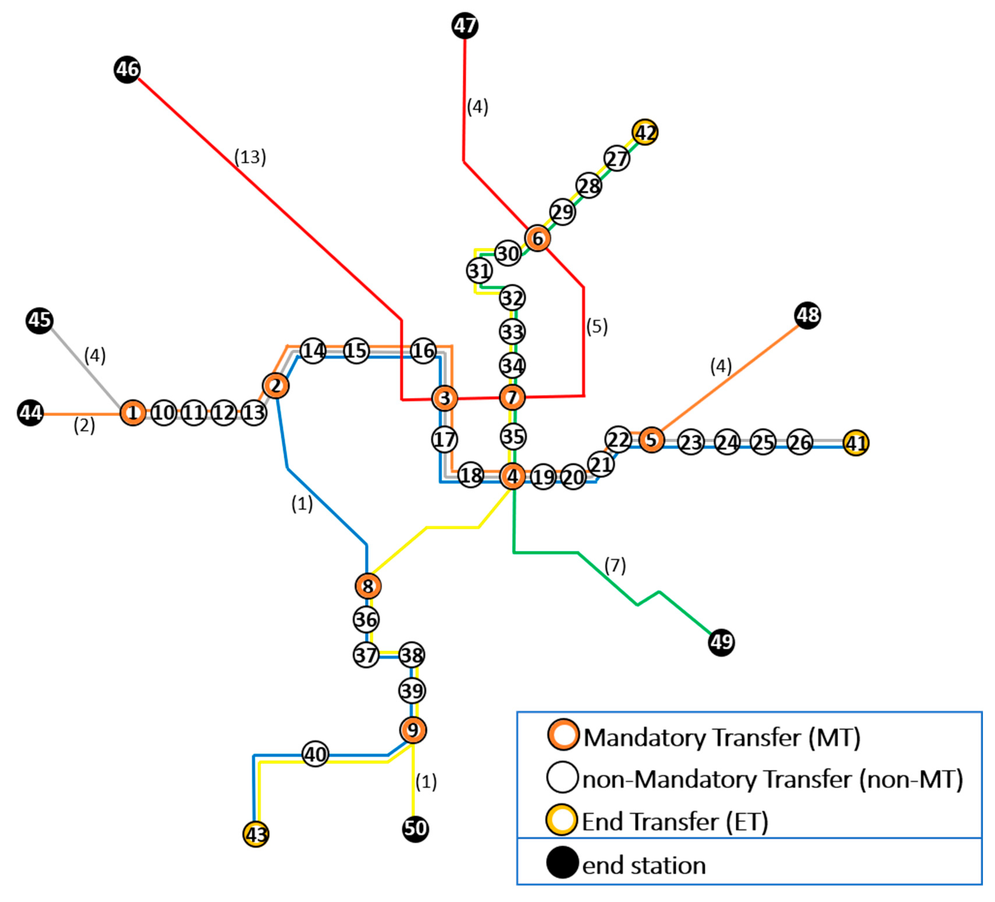
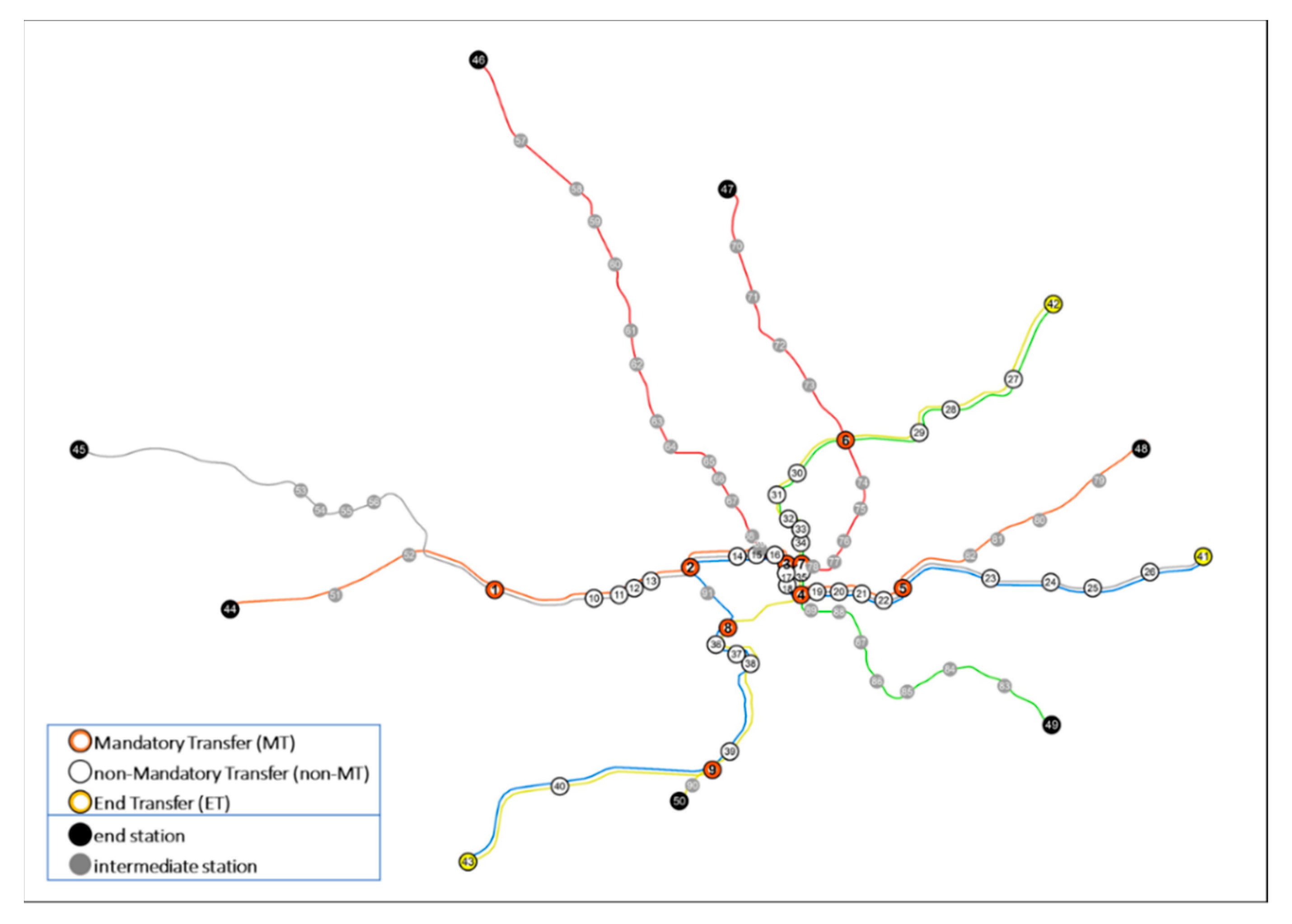
Figure 2 shows the complete structure of the WMATA network, with three types of transfer stations (9 MTs, 31 non-MTs, and 3 ETs) as well as end stations and intermediate stations, as of 2015. The WMATA network has moderate complexity, making it more appropriate for the case study than other rail networks in the United States, which have either an overly simple star- or tree-shaped structure, such as the Metropolitan Atlanta Rapid Transit Authority (MARTA) and the Greater Cleveland Regional Transit Authority (GCRTA) networks, or are too large, with hundreds of nodes such as the New York City Transit (NYCT) network, and too complicated by inner-loop lines such as the Miami-Dade Transit (MDT) network [4].
This research used travel distance between stations from i to j as Cij, because travel distances between stations are a much more reliable measurement than travel time. Travel time in a transit system could include the time involved in waiting, transferring, and scheduling. Theoretically, considering those times as network costs is more desirable. However, those metrics are often less predictable. For example, the durations of waiting and transferring times at stops are significantly influenced by crowding conditions such as those related to peak versus non-peak hours [34]. Thus, we define travel distance as Cij. The station-to-station distance was obtained using the Washington Metropolitan Area Transit Authority API [33]. The distance is given in miles, and the station-to-station distance ranges from 0.29 to 5.65 miles, with an average of 1.25 miles. For a better representation of connectivity information for the WMATA network, a graph is provided in Figure A1. Table 2 lists station names for 9 MT stations and describes their link attributes. For a complete list of stations and station types, refer to Table A1. The OD passenger flow (Wst) of the WMATA network was obtained from the webpage PlanItMetro and Open Data DC of the Washington Metropolitan Area Transit Authority [35,36]. The most recent publicly available OD flow dataset was for October 2015. The dataset provided OD flow information on average daily trips by each day of week (Monday through Sunday) based on all trips during October 2015. Our concern was the 9 MTs, allowing the idea of partial node failures to be applied.
As can be seen in Figure 3, most MTs have their least ridership on Sunday and Saturday and their greatest on Monday, in accordance with the ridership of the entire network for the seven days of week. Accordingly, it was expected that most MT maintenance (which causes only partial node failure at MTs) could be carried out on Sunday and Saturday, specifically avoiding Monday, to minimize its influence on passengers departing from and arriving at the MT. The following section presents the results of analysis in which a passenger reroute is the key point to be addressed when minimizing the influence of partial node failure on network flow distribution.

4.2. Computational Results: The Impact of Partial Node Failure of MTs in the WMATA Network

The analysis focused on the criticality of MTs because of their unique roles in transferring passengers within the network. Table 3 presents the complete list of computational results relating to the impact of partial node failure of MTs for a week during October 2015. With the SPNPr model, nodal disruption scenarios for the nine MTs were conducted; a total of 70 partial failure scenarios were carried out to optimize the network flow distribution based on shortest paths using the model, including 7 scenarios at status quo and 63 scenarios for partial node failure of the nine MTs on Monday to Sunday and monthly as a whole. Among the 72 partial node failure scenarios, each scenario simulated the partial node failure of one MT using OD flow on a specific day. The objective values were for the entire network, assuming that all passengers would take the path offering the shortest distance from origin to destination. All problems were solved to optimality within 12 s using CPLEX 12 on an Intel i7 processor paired with 16 GB of RAM. The performance of the models is also represented based on the number of iterations and the number of nodes in the last column. The number of branches and bounds (B&B), a popular indicator used to examine the model’s performance is 0 for all instances. For comparison with previous work by Kim et al. [5], Table 4 presents the overall criticality of stations using the mean of the objective values for seven days and the ranges for the partial failure of each MT. Given this “averaged” perspective, MT6 is the most critical, followed by MT5 and MT1, unlike in the result obtained by Kim et al. [5], where MT7 was not listed in any top 10 criticality rankings when assessing network reliability measures. However, the mean of CostPrreroute supports the previous research by Kim et al. [5], whose analysis highlighted three bridge stations (L’Enfant Plaza, Metro Center, and Gallery Place) that were critical when they used network reliability measures. Interestingly, the station MT8 (Pentagon), pointed out as a critical station in their study, was ranked low: 8th among nine MTs.
From the perspective of a maintenance schedule, the partial node failure scenarios can present which day is the best, or an alternative day, if partial node failure is expected in MT. Table 5 summarizes on which day of the week a partial node failure of a MT caused the least and second-least flow rerouting costs. The assumption of “best day for MT maintenance” concerned passengers whose origin or destination were not the partially failed MT; they would complete their trips via the alternative path in the enclosed WMATA network without the need for other transportation modes. For each MT, among the seven days of the week, a day was considered the best on which to schedule maintenance for a MT having partial node failure if CostPrreroute was the least. Likewise, the alternative day, which was the second-best day for MT maintenance, could be obtained from the second-smallest value of CostPrreroute. As presented, Sunday was the best day for maintenance of seven MTs, but MT2 and MT8 have different best days of Saturday and Wednesday, respectively. Notice that the lowest amount of flows (objective values) among the seven days did not necessarily indicate the best day for maintenance. Usually, the lowest flows were anticipated on Sunday; however, for MT2 and MT8, the reroute costs were least on Saturday and Wednesday, respectively. The MTs are arranged by descending order of CostPrreroute and thus reflect criticality ranking of MTs. Rankings for both the best day and alternative day for MT maintenance consistently indicate that MT3 was the most critical MT for the maintenance schedule. However, when comparing the percentage increase of flow reroute cost on the best day and the alternative day, the percentage increase ranged widely, from 6.1% to 89.1%, so that for some MTs only the best day might be considered so as to avoid considerable network costs for passengers. For example, MT1′s rerouting cost (ranked 6th) was relatively small, but choosing the second-best day, Saturday, increased the rerouting cost to 89%, so that Sunday was substantially better than Saturday for maintenance MT1. In contrast, the maintenance for MT8 could be conducted either on Wednesday (best) or Tuesday (alternative), whose difference in flow reroute cost was quite small (6.4%).

4.3. Impacted Stations with Increased ViaFlow

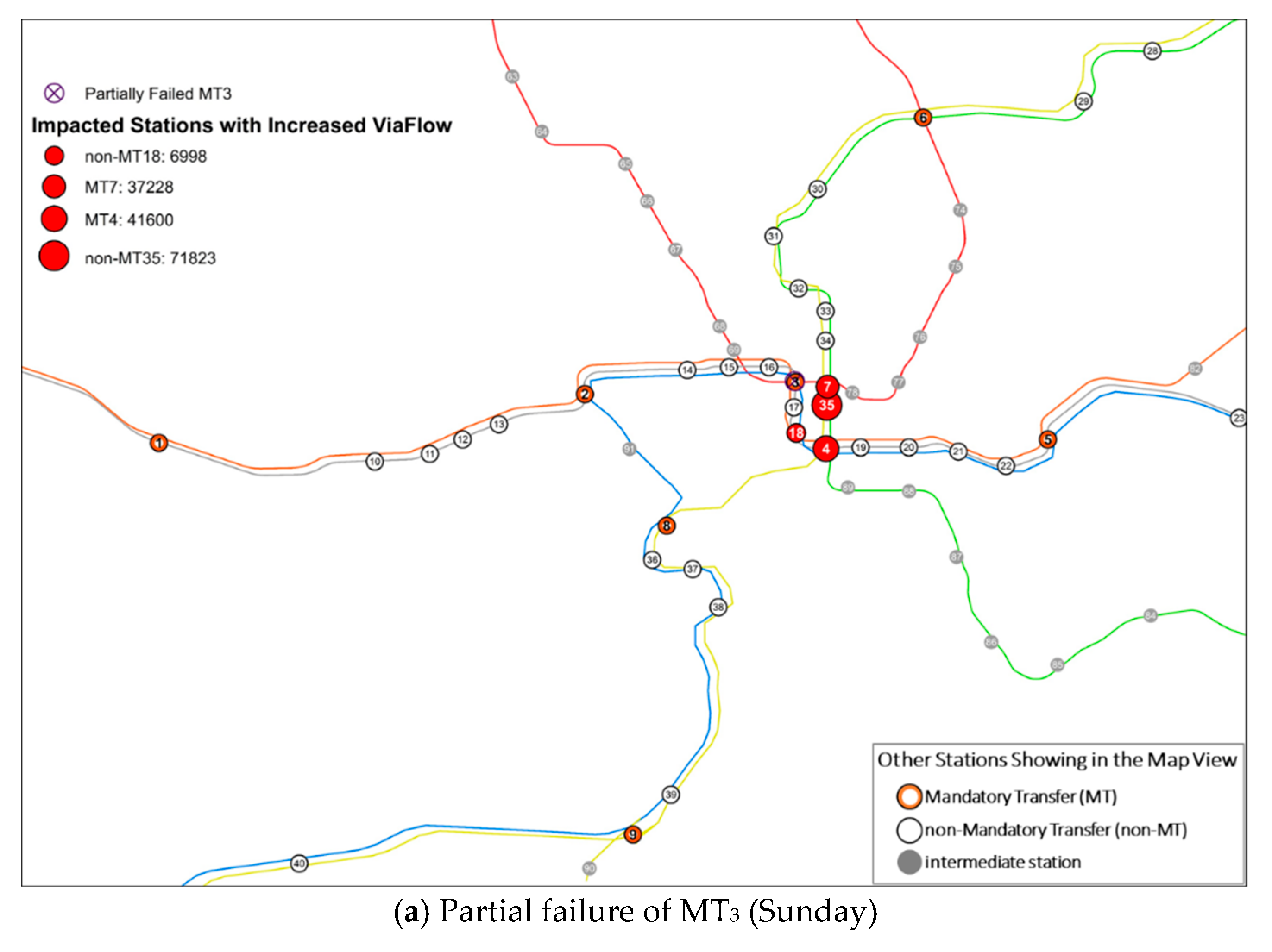
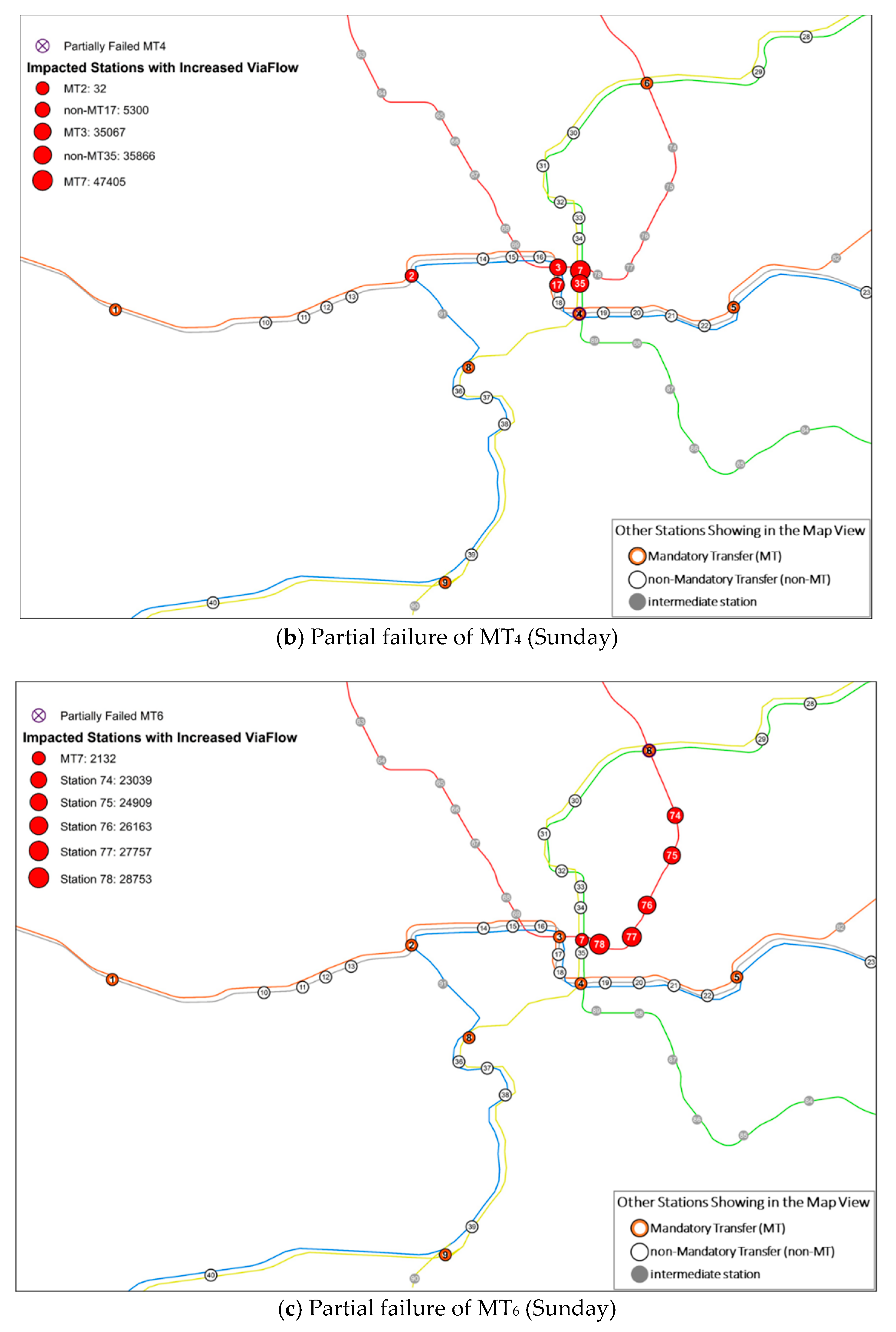
The information regarding increased ViaFlow is important for examining the redistribution of network flow and evaluating the level of traffic load on each station because of the flow reroutes caused by a partially failed MT. With this information, decision-makers and management staff can prepare for a flow increase at specific station(s). In each partial node failure scenario, the DiffViaFlowkPr-Sq at each node could be obtained by subtracting ViaFlowkSq from ViaFlowkPr. If the DiffViaFlowkPr-Sq is positive, the node k has more ViaFlow (i.e., more passengers pass through node k) when MTr partially fails than at status quo. Among the nine MT partial failure scenarios on their best day for maintenance, stations were impacted with increased ViaFlow in only four scenarios—the partial node failures of MT3, MT4, MT6, and MT7. For the other five scenarios, all stations experienced decreased or unchanged ViaFlow. Table 6 summarizes the list of critical stations with increased ViaFlow. Two findings are worthy of note: First, the impact of the partial node failure manifested with a different scope and magnitude over the network. For example, the partial failure of MT3 affected only four stations, but that of MT7 affected nine. Interestingly, a partially failed MT triggered other MTs consecutively, and those affected MTs also could cause a chain of delays or cumulative congestion at the other stations. For example, a partial failure of MT3 directly affected MT4 and MT7, and two MTs delivered their increased flows to other MTs. Thus, a chain reaction resulting from the partial node failure of {MT3 → MT4 → MT7, MT3, MT2} is a feasible scenario. Second, in general, the DiffViaFlow informs decision-makers’ choice of which stations should be prepared for increased passengers (i.e., the greater the value, the more critical). However, comparing the values of ViaFlowkPr with DiffViaFlow can guide understandings of which scenario is more critical than others. For example, the partial failure of MT6 on Sunday resulted in the least increase of passengers (+2,132) at station 7, which was not a substantial figure compared with stations 78, 77, 76, 75, and 74 (> +20,000). However, station 7 kept the largest ViaFlow after partial failure of MT6, which might experience a more critical situation than other affected stations. In short, examination of changes in flow balance by partial node failure provides a more realistic guideline for decision-makers to prepare pre- or post-failure plans.
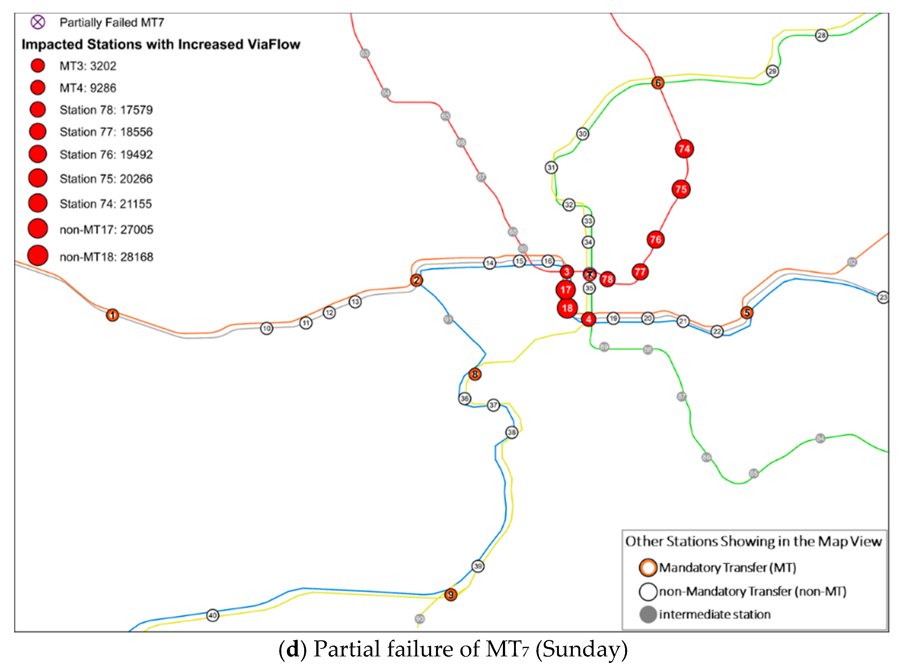
Combined with Table 6, Figure 4 visualizes the scenarios, showing how the partial failure of the MTs listed in Table 5 affected the stations (indicated by red dots). The figures clearly show the locations of impacted stations and how much they were impacted. Note that when a MT partially failed, not only did some of the directly connected stations experience an increase of ViaFlow, but so also did some of the indirectly connected stations, despite being far from the failed MT. Figure 4a displays a typical scenario where the impact manifested only near stations. In contrast, Figure 4b exhibits a different type of scenario from that dealt with in Figure 4a, because the partial failure of the MT4 affected not only the directly connected station 37 with the increase of 35,866 of ViaFlow but also some nearby indirectly connected stations (i.e., MT3, MT7, MT2 and station 17) hosting 32 to 47,405 more ViaFlows. Figure 4c,d shows another type of scenario in which the impact was formed over the stations in one direction through a single line, but other lines were not significantly affected.

5. Concluding Remarks

The concept of a partial node failure is a critical concern for networks that are mainly operated with a mandatory transfer station, because MTs usually face partial disruption rather than complete failure of operation. Given this assumption, examining partial MT failure scenarios for the MTs is a more realistic practice for managing networks with a view to making their operation more reliable. The influence of partial node failure on the entire network can be assessed by measuring increased network costs, in terms of reroute costs for the partial node scenarios. The assessments were focused on identifying the critical MTs, gauging the magnitude of the impact from the partial node failure of MTs, and proposing the best and alternative days if the maintenance schedule was of concern. The major contributions of this paper are summarized as follows. First, the study extended the SPN model by adding two elements for partial node failure: cost update (d’ij) and link attribute (lij). To implement partial node failure in the SPN model, the cost matrix is updated for each scenario; the link attribute was necessary for computation of the cost update. Second, two indicators were constructed with which to assess the impact of partial node failures on network flow distribution based on the shortest paths: the additional network cost caused by flow reroute cost (CostPrreroute) and the change in flow passing through each node (DiffViaFlowkPr-S). Third, from a practical perspective, the assessment procedure in this study demonstrated a way of identifying the proper day for scheduling heavy maintenance or a major upgrade to a rail station in terms of least additional network cost caused by passenger reroutes and of predicting the change in pass-through traffic at every station so long as OD flow can be accurately estimated for a future period. Fourth, the study addressed the impact of temporal scales on the criticality rankings of stations, emphasizing the importance of identifying proper temporal scale for data analysis in transportation planning. Various results regarding partial node failures are specifically useful for policymaking and operations management, because partial node failures are more likely than extreme scenarios in real-world situations.
Based on our studies, the study can be extended and further developed in several directions. The first possible direction is to implement the arc flow constraint or node flow constraint in the numerical experiment if information on the arc capacity or node capacity is available. As underscored by a study by Ye and Kim [11] and a nuance from the results in Figure 4, the impact of nodal disruption can manifest differently geographically over the network when arc capacity for flow distributions is considered than when considering the results from non-capacitated models. A second possible direction involves analyzing the reassignment of unrealized flows (i.e., flows departing from and arriving at the partially failed node) at the partially failed node—a possibility that nonetheless has not been considered in this paper, for two reasons: First, the amount of unrealized flows could be easily identified by looking at ridership at status quo; second, reassignment of these flows at the partially failed node could be complicated by other modes in practice (e.g., it is uncertain how passengers or cargos would access the network by connecting to other transportation modes such as bus, taxi, bicycle, or even foot).
Future research could study how to allocate the unrealized travel demand at a partially failed station, assuming that passengers would take the metro rail to reach their destinations in any event. Taking the partial node failure of a MT in the WMATA network as an example, if the partially failed MT is not their origin or destination, passengers can complete their trip—at most via a longer reroute path—because none of the partially failed MTs would separate the WMATA network into two or more subnetworks. However, if the partially failed MT is their origin, passengers might walk or bike or take a bus to a nearby alternative station to get on the train. If the partially failed MT is their destination, passengers might choose to get off the train at a nearby alternative station and walk or cycle or take a bus to their destination. Here the alternative stations are defined as those stations that directly connect with the partially failed MT. Finally, it is beneficial to analyze the reassignment of unrealized flows by incorporating networks of other transportation modes such as bus routes to find out whether there is any better alternative plan for rerouting passengers so as to minimize the additional network costs.

Author Contributions

Conceptualization, H.K. and Q.Y.; methodology, H.K. and Q.Y.; formal analysis, H.K. and Q.Y.; writing—original draft preparation, Q.Y.; writing—review and editing, H.K.; visualization, Q.Y.

Funding

This research received no external funding.

Conflicts of Interest

The authors declare no conflict of interest.

Appendix A

Figure A1. The Washington Metropolitan Area Transit Authority (WMATA) network, Washington, DC. Note: The network was drawn by the authors based on the WMATA information [37]. Only transfer nodes and end nodes are shown in the network. The value in parentheses indicates the number of intermediate nodes on that arc. The graph is dedicated to present network connectivity, not proportional to physical distance.
Sustainability 11 06275 g0a1
Table A1. Station ID, name, type, and link attribute of the WMATA network, 2015.
Station IDStation NameTypeLink Attribute *
1East Falls ChurchMTO, S
2RosslynMTB, O, S
3Metro CenterMTB, O, R, S
4L’Enfant PlazaMTB, G, O, S, Y
5Stadium-ArmoryMTB, O, S
6Fort TottenMTG, R, Y
7Gallery Place/ChinatownMTG, R, Y
8PentagonMTB, Y
9King St-Old TownMTB, Y
10Ballston-MUnon-MTO, S
11Virginia Square-GMUnon-MTO, S
12Clarendonnon-MTO, S
13Court Housenon-MTO, S
14Foggy Bottom-GWUnon-MTB, O, S
15Farragut Westnon-MTB, O, S
16McPherson Squarenon-MTB, O, S
17Federal Trianglenon-MTB, O, S
18Smithsoniannon-MTB, O, S
19Federal Center SWnon-MTB, O, S
20Capitol Southnon-MTB, O, S
21Eastern Marketnon-MTB, O, S
22Potomac Avenon-MTB, O, S
23Benning Rdnon-MTB, S
24Capitol Heightsnon-MTB, S
25Addison Rd/Seat Pleasantnon-MTB, S
26Morgan Blvdnon-MTB, S
27College Park-U of Mdnon-MTG, Y
28Prince George’s Plazanon-MTG, Y
29West Hyattsvillenon-MTG, Y
30Georgia Ave-Petworthnon-MTG, Y
31Columbia Heightsnon-MTG, Y
32U St/African-Amer Civil War Memorial/Cardozonon-MTG, Y
33Shaw-Howard Univnon-MTG, Y
34Mt Vernon Sq/7th St-Convention Centernon-MTG, Y
35Archives/Navy Memorial-Penn Quarternon-MTG, Y
36Pentagon Citynon-MTB, Y
37Crystal Citynon-MTB, Y
38Ronald Reagan Washington National Airportnon-MTB, Y
39Braddock Rdnon-MTB, Y
40Van Dorn Stnon-MTB, Y
41Largo Town CenterETB, S
42GreenbeltETG, Y
43Franconia-SpringfieldETB, Y
44Vienna/Fairfax-GMUESO
45Wiehle-Reston EastESS
46Shady GroveESR
47GlenmontESR
48New CarrolltonESO
49Branch AveESG
50HuntingtonESY
51Dunn Loring/MerrifieldISO
52West Falls Church/VT/UVAISO
53Spring HillISS
54GreensboroISS
55Tysons CornerISS
56McLeanISS
57RockvilleISR
58TwinbrookISR
59White FlintISR
60Grosvenor-StrathmoreISR
61Medical CenterISR
62BethesdaISR
63Friendship HeightsISR
64Tenleytown-AUISR
65Van Ness-UDCISR
66Cleveland ParkISR
67Woodley Park/Zoo/Adams MorganISR
68Dupont CircleISR
69Farragut NorthISR
70WheatonISR
71Forest GlenISR
72S SpringISR
73TakomaISR
74Brookland-CUAISR
75Rhode Island Ave/BrentwoodISR
76NoMa-Gallaudet UISR
77Union StationISR
78Judiciary SquareISR
79LandoverISO
80CheverlyISO
81DeanwoodISO
82Minnesota AveISO
83SuitlandISG
84Naylor RdISG
85Southern AveISG
86Congress HeightsISG
87AnacostiaISG
88Navy Yard-BallparkISG
89WaterfrontISG
90Eisenhower AveISY
91Arlington CemeteryISB
Note: MT: mandatory transfer, non-MT: non-mandatory transfer, ET: end transfer (i.e., transfer station located at the end of the line), IS: intermediate station, and ES: ending station (i.e., station located at the end of line). * Link attribute: R: red, O: orange, G: green, Y: yellow, B: blue, S: silver.

References

  1. O’Kelly, M.E. Network hub structure and resilience. Netw. Spat. Econ. 2015, 15, 235–251. [Google Scholar] [CrossRef]
  2. Matisziw, T.; Murray, A.; Grubesic, H. Exploring the vulnerability of network infrastructure to interdiction. Ann. Reg. Sci. 2009, 43, 307–321. [Google Scholar] [CrossRef]
  3. Kim, H. Geographical analysis on network reliability of public transportation systems: A case study of subway network system in Seoul. J. Korean Geogr. Soc. 2009, 44, 187–205. [Google Scholar]
  4. Ye, Q.; Kim, H. Assessing network vulnerability of heavy rail systems with the impact of partial node failures. Transportation 2019, 46, 1591–1614. [Google Scholar] [CrossRef]
  5. Kim, H.; Kim, C.; Chun, Y. Network reliability and resilience of rapid transit systems. Prof. Geogr. 2016, 68, 53–65. [Google Scholar] [CrossRef]
  6. Cats, O.; Jenelius, E. Beyond a complete failure: The impact of partial capacity degradation on public transport network vulnerability. Transportmetrica B 2016, 6, 77–96. [Google Scholar] [CrossRef]
  7. Duggan, P.; Siddiqui, F.; Aratani, L. Washington Post: For Metro Riders, Summer Starts with Partial Shutdown of 3 Rail Lines. Available online: https://www.washingtonpost.com/local/trafficandcommuting /for-metro-riders-summer-starts-with-a-partial-shutdown-of-three-rail-lines-as-part-of-safetrack/2016/06/20/b932e62e-3668-11e6-a254-2b336e293a3c_story.html (accessed on 17 October 2019).
  8. Nagurney, A.; Qiang, Q. Robustness of transportation networks subject to degradable links. Europhys. Lett. 2007, 80, 68001. [Google Scholar] [CrossRef]
  9. Sullivan, J.L.; Novak, D.C.; Aultman-Hall, L.; Scott, D.M. Identifying critical road segments and measuring system-wide robustness in transportation networks with isolating links: A link-based capacity-reduction approach. Transp. Res. Part A 2010, 44, 323–336. [Google Scholar] [CrossRef]
  10. Burgholzer, W.; Bauer, G.; Posset, M.; Jammernegg, W. Analysing the impact of disruptions in intermodal transport networks: A micro simulation-based model. Decis. Support Syst. 2013, 54, 1580–1586. [Google Scholar] [CrossRef]
  11. Ye, Q.; Kim, H. Assessing network vulnerability using shortest path network problems. J. Transp. Saf. Secur. 2019. [Google Scholar] [CrossRef]
  12. O’Kelly, M.E.; Kim, H.; Kim, C. Internet reliability with realistic peering. Environ. Plan. B 2006, 33, 325–343. [Google Scholar] [CrossRef]
  13. Matisziw, T.; Murray, A.; Grubesic, H. Strategic network restoration. Netw. Spat. Econ. 2010, 10, 345–361. [Google Scholar] [CrossRef]
  14. Kim, H.; Ryerson, M. The q-Ad hoc hub location problem for multi-modal networks. Netw. Spat. Econ. 2017, 17, 1015–1041. [Google Scholar] [CrossRef]
  15. Chen, Y.; Yang, H. Shortest paths in traffic-light networks. Transp. Res. Part B 2000, 34, 241–253. [Google Scholar] [CrossRef]
  16. Sherali, H.D.; Hobeika, A.G.; Kangwalklai, S. Time-Dependent, Label-Constrained Shortest Path Problems with Applications. Transp. Sci. 2003, 37, 278–293. [Google Scholar] [CrossRef]
  17. Santosa, L.; Coutinho-Rodrigues, J.; Current, J.R. An improved solution algorithm for the constrained shortest path problem. Transp. Res. Part B 2007, 41, 756–771. [Google Scholar] [CrossRef] [Green Version]
  18. Cappanera, P.; Scaparra, M.P. Optimal allocation of protective resources in shortest-path networks. Transp. Sci. 2011, 45, 64–80. [Google Scholar] [CrossRef]
  19. Wang, L.; Yang, L.; Gao, Z. The constrained shortest path problem with stochastic correlated link travel times. Eur. J. Oper. Res. 2016, 255, 43–57. [Google Scholar] [CrossRef]
  20. Shi, N.; Zhou, S.; Wang, F.; Tao, Y.; Liu, L. The multi-criteria constrained shortest path problem. Transp. Res. Part E 2017, 101, 13–29. [Google Scholar] [CrossRef]
  21. Strehler, M.; Merting, S.; Schwan, C. Energy-efficient shortest routes for electric and hybrid vehicles. Transp. Res. Part B 2017, 103, 111–135. [Google Scholar] [CrossRef]
  22. Dijkstra, E.W. A note on two problems in connexion with graphs. Numer. Math. 1959, 1, 269–271. [Google Scholar] [CrossRef] [Green Version]
  23. Whiting, P.D.; Hillier, J.A. A method for finding the shortest route through a road network. J. Oper. Res. Soc. 1960, 11, 37–40. [Google Scholar] [CrossRef]
  24. Ford, L.R., Jr. Network Flow Theory; Paper P-923; RAND Corporation: Santa Monica, CA, USA, 1956. [Google Scholar]
  25. Bellman, R. On a routing problem. Q. Appl. Math. 1958, 16, 87–90. [Google Scholar] [CrossRef] [Green Version]
  26. Floyd, R.W. Algorithm 97: Shortest path. Commun. ACM. 1962, 5, 345. [Google Scholar] [CrossRef]
  27. Johnson, D.B. Efficient algorithms for shortest paths in sparse networks. J. ACM. 1977, 24, 1–13. [Google Scholar] [CrossRef]
  28. Bock, F.; Kantner, H.; Haynes, J. An Algorithm (the rh Best Path Algorithm) for Finding and Ranking Paths Through a Network; Research Report; Armour Research Foundation: Chicago, IL, USA, 1957. [Google Scholar]
  29. Bellman, R.; Kalaba, R. On kth best policies. J. Soc. Ind. Appl. Math. 1960, 8, 582–588. [Google Scholar] [CrossRef]
  30. Clarke, S.; Krikorian, A.; Rausan, J. Computing the N best loopless paths in a network. J. Soc. Ind. Appl. Math. 1963, 11, 1096–1102. [Google Scholar] [CrossRef]
  31. Kuby, M.; Xu, Z.; Xie, X. A minimax method for finding the k best “differentiated” paths. Geogr. Anal. 1997, 29, 298–313. [Google Scholar] [CrossRef]
  32. Grubesic, T.H.; Matisziw, T.C.; Murray, A.T.; Snedicker, D. Comparative approaches for assessing network vulnerability. Int. Reg. Sci. Rev. 2008, 31, 88–112. [Google Scholar] [CrossRef]
  33. Washington Metropolitan Area Transit Authority API. Available online: https://developer.wmata.com (accessed on 11 November 2017).
  34. Haywood, L.; Koning, M. Estimating Crowding Costs in Public Transport. DIW Berlin Discussion Paper No. 1293. 2013. Available online: http://dx.doi.org/10.2139/ssrn.2256332 (accessed on 17 October 2019).[Green Version]
  35. PlanItMetro. Metrorail Ridership Data by Washington Metropolitan Area Transit Authority. Available online: https://planitmetro.com/?s=Metrorail+Ridership+Data+Download%2C+October+2015 (accessed on 11 November 2017).
  36. Open Data DC. Available online: https://opendata.dc.gov/datasets/metro-stations-regional; https://opendata.dc.gov/datasets/metro-lines-regional (accessed on 2 April 2018).
  37. WMATA. Available online: https://www.wmata.com/about/upload/Metro-Facts-2015.pdf (accessed on 11 November 2017).
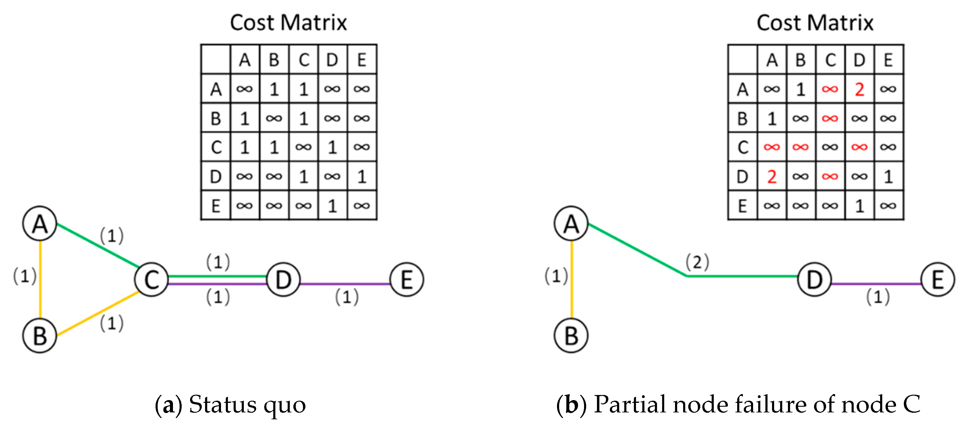
Figure 1. The procedure of cost update in cost matrix after partial node failure.
Sustainability 11 06275 g001
Figure 2. The Washington Metropolitan Area Transit Authority (WMATA) network (proportional to real physical distance), 2015. Note: The network was drawn by the authors using GIS based on the WMATA information [33].
Sustainability 11 06275 g002
Figure 3. Daily average ridership of the nine MTs in October 2015.
Sustainability 11 06275 g003
Figure 4. Impacted stations with increased ViaFlow on the best day for maintenance of MT3, MT4, MT6, and MT7 of the WMATA network in October 2015.
Sustainability 11 06275 g004aSustainability 11 06275 g004bSustainability 11 06275 g004c
Table 1. Numerical results of the sample network at status quo and when MTC partially fails.
Key ElementsValue
ΩPc28
Ω S q c 34 − 10 = 24
cos t r e r o u t e P c 28 − 24 = 4
NodeFlowASq8
RidershipASq8
NodeFlowAPc14
RidershipAPc6
ViaFlowASq(8 − 8)/2 = 0
ViaFlowAPc(14 − 6)/2 = 4
DiffViaFlowAPc-Sq4 − 0 = +4
Table 2. Mandatory transfer (MT) stations and link (line) attributes of the WMATA network, 2015.
Type of StationStation NameLink (Line) Attribute
MT1East Falls ChurchOrange, Silver
MT2RosslynBlue, Orange, Silver
MT3Metro CenterBlue, Orange, Red, Silver
MT4L’Enfant PlazaBlue, Green, Orange, Silver, Yellow
MT5Stadium–ArmoryBlue, Orange, Silver
MT6Fort TottenGreen, Red, Yellow
T7Gallery Place/ChinatownGreen, Red, Yellow
MT8PentagonBlue, Yellow
MT9King St.–Old TownBlue, Yellow
Note: MT: mandatory transfer station.
Table 3. Results of partial node failure scenarios for MTs for all seven days of the week.
Partial Node FailureDayObj. Values C o s t r e r o u t e P r Sol. Time (sec.)# of Iterations
Status quoMonday8,938,458N/A9.9150,742
Tuesday7,011,337N/A9.9550,929
Wednesday7,064,503N/A9.9250,858
Thursday7,353,972N/A11.1751,002
Friday7,408,573N/A10.1350,742
Saturday4,816,424N/A11.3650,609
Sunday3,526,568N/A11.1649,939
MT1Monday8,823,26769749.2549,767
MT1Tuesday6,918,68755409.4149,549
MT1Wednesday6,971,92256479.5249,695
MT1Thursday7,255,28759929.3849,775
MT1Friday7,304,42667029.5849,789
MT1Saturday4,703,42338789.2549,399
MT1Sunday3,436,93420519.5848,607
MT2Monday8,725,02342,4259.0044,382
MT2Tuesday6,856,64834,8409.0844,289
MT2Wednesday6,910,94035,5959.1644,192
MT2Thursday7,203,26438,8939.0344,159
MT2Friday7,262,98340,3259.3044,400
MT2Saturday4,730,39225,0039.0643,911
MT2Sunday3,356,16932,2739.2743,394
MT3Monday8,609,317180,9339.0043,811
MT3Tuesday6,785,886146,5729.0043,759
MT3Wednesday6,841,368149,8358.9744,161
MT3Thursday7,136,343160,3628.9144,019
MT3Friday7,218,614171,3089.7843,665
MT3Saturday4,729,130121,5668.8943,350
MT3Sunday3,472,25782,5169.1343,013
MT4Monday8,739,334114,4878.3832,916
MT4Tuesday6,815,57796,7678.4532,954
MT4Wednesday6,869,54499,3148.4832,867
MT4Thursday7,168,453107,2438.4233,004
MT4Friday7,286,959116,1259.1633,049
MT4Saturday4,778,63990,1388.4132,736
MT4Sunday3,491,88460,2868.5332,329
MT5Monday8,890,79118919.6649,911
MT5Tuesday6,963,51815509.3449,716
MT5Wednesday7,005,76114669.7249,863
MT5Thursday7,302,76517719.8449,736
MT5Friday7,287,289196010.2249,767
MT5Saturday4,662,28115839.6449,322
MT5Sunday3,473,95812449.4548,970
MT6Monday8,848,17094,3016.3927,903
MT6Tuesday6,944,76470,1246.4227,894
MT6Wednesday6,995,61670,2296.4127,863
MT6Thursday7,282,47372,8706.5927,949
MT6Friday7,339,10778,7516.9527,960
MT6Saturday4,776,99460,1946.3427,636
MT6Sunday3,495,97139,6066.4827,255
MT7Monday8,607,38391,9788.7747,265
MT7Tuesday6,760,52773,4109.0047,257
MT7Wednesday6,818,07574,3459.3847,220
MT7Thursday7,100,14677,8629.3447,179
MT7Friday7,149,93790,14010.2547,342
MT7Saturday4,613,31365,9479.3646,796
MT7Sunday3,406,13238,6378.8846,421
MT8Monday8,724,54412069.6148,469
MT8Tuesday6,813,7128059.4448,547
MT8Wednesday6,862,9687579.3748,444
MT8Thursday7,151,36110579.3648,610
MT8Friday7,219,60798211.2548,662
MT8Saturday4,763,01713209.6148,255
MT8Sunday3,309,21416289.5947,575
MT9Monday8,662,7227159.3849,706
MT9Tuesday6,804,82659410.0349,959
MT9Wednesday6,854,9736119.5249,627
MT9Thursday7,136,9226129.7249,809
MT9Friday7,190,44567110.1749,785
MT9Saturday4,663,0324139.6649,589
MT9Sunday3,408,3512879.5048,999
Note: The branch and bound value is 0 for all instances.
Table 4. Overall criticality rankings based on the mean of objective values and the range for a week.
Criticality *StationMean of obj. ValuesStationMean of C o s t r e r o u t e P r
1MT66,526,156MT3144,727.4
2MT56,512,338MT497,765.7
3MT16,487,707MT773,188.4
4MT46,450,056MT669,439.3
5MT26,435,060MT235,622.0
6MT86,406,346MT15254.9
7MT36,398,988MT51637.9
8MT96,388,753MT81107.9
9MT76,350,788MT9557.6
* Note: 1 = most critical, 9 = least critical.
Table 5. Best day for MT maintenance under partial node failure scenarios.
MTDay C o s t r e r o u t e P r
Best Day for MT MaintenanceMT3Sunday82,516
MT4Sunday60,286
MT6Sunday39,606
MT7Sunday38,637
MT2Saturday25,003
MT1Sunday2051
MT5Sunday1244
MT8Wednesday757
MT9Sunday287
Alternative Day for MT MaintenanceMT3Saturday121,566 (47.3%)
MT4Saturday90,138 (49.5%)
MT7Saturday65,947 (70.7%)
MT6Saturday60,194 (52.0%)
MT2Sunday32,273 (29.1%)
MT1Saturday3878 (89.1%)
MT5Wednesday1466 (17.9%)
MT8Tuesday805 (6.4%)
MT9Saturday413 (43.9%)
Table 6. MTs with increased ViaFlow on their best day for maintenance of the WMATA network.
Station IDViaFlowksqViaFlowkPrDiffViaFlowkPr-sq
MT3 Partially Fails (Sunday)3560,854132,677+71,823
4153,684195,284+41,600
7117,004154,232+37,228
1865,23372,231+6998
Total increase: +157,649
MT4 Partially Fails (Sunday)7117,004164,409+47,405
3560,85496,720+35,866
3148,726183,793+35,067
1777,82083,120+5300
277,62077,652+32
Total increase: +123,670
MT6 Partially Fails (Sunday)7835,89964,652+28,753
7718,97946,736+27,757
7615,92142,084+26,163
7512,24637,155+24,909
74682329,862+23,039
7117,004119,136+2132
Total increase: +132,753
MT7 Partially Fails (Sunday)1865,23393,401+28,168
1777,820104,825+27,005
74682327,978+21,155
7512,24632,512+20,266
7615,92135,413+19,492
7718,97937,535+18,556
7835,89953,478+17,579
4153,684162,970+9286
3148,726151,928+3202
Total increase: +164,709