Article

Structural Monitoring and Safety Assessment during Translocation of Mahavira Hall of Jade Buddha Temple

1
Department of Disaster Mitigation for Structures, Tongji University, Shanghai 200092, China
2
Department of Architecture, Tohoku Institute of Technology, Sendai 982-8577, Japan
3
School of Civil and Environmental Engineering, Harbin Institute of Technology, Shenzhen 518055, China
*
Author to whom correspondence should be addressed.
Sustainability 2019, 11(19), 5477; https://doi.org/10.3390/su11195477
Submission received: 20 August 2019 / Revised: 24 September 2019 / Accepted: 30 September 2019 / Published: 2 October 2019
(This article belongs to the Section Sustainable Urban and Rural Development)

Abstract

:
The Mahavira Hall of the Jade Buddha Temple in Shanghai, China is a century-old traditional timber structure with a post-and-lintel construction. To improve the temple’s architectural layout and enhance the lintel structural integrity, the Mahavira Hall was moved 30.66 m and then elevated 1.05 m in September 2017. To assist in the structural translocation and uplift, the authors designed a monitoring system to continuously measure the relative displacement and inclination of the overall structure, individual components, and inside statues to ensure the integrity of the hall and its contents. This article presents and summarizes the priority issues and principles of monitoring the ancient Chinese timber structure. The time series of monitored data are decimated in order to minimize the fluctuation of data. The structural integrity of the Mahavira Hall was evaluated based on the inclination angle of its vital members. Finally, combined with the limit value regulated by code and the predicted early warning threshold values, which are based on extreme value theory, the effect of the translocation on the structural performance was obtained using fuzzy logic.

1. Introduction

The Mahavira Hall of the Jade Buddha Temple represents a traditional Chinese timber architecture and is the main hall for religious ceremonies [1]. In order to extend the space in front of the main hall for religious ceremonies, the Mahavira Hall was moved north by 30.66 m and then lifted up by 1.05 m in September 2017. Because structural translocation will not change the original appearance of the building, it usually leads to lower cost and shorter time compared with rebuilding [2,3,4].
As a traditional Chinese timber architecture, the Mahavira Hall has bracket systems known as Dou-Gou and mortise-tenon joints used as connections [5,6]. As a crucial part of the timber structure, the Dou-Gon and its joints have significant effects on the overall structural behaviors [7]. The connections are often the weakest links in timber structures [8], and the degradation of connections are often the cause of crucial structural deformation and deterioration [9]. In addition, all the inside Buddha statues, which have wooden skeletons and clay surfaces, were moved together with the hall. Considering the vulnerable aspects of the Mahavira Hall, this project required more stringent process control during translocation. Several critical steps, including structural strengthening, monitoring, soil treatment, and translocation control [10,11,12], were adopted to minimize the safety risk during the moving process.
To evaluate the effect of translocation on the structural integrity, assessment methods were needed to appraise the structural safety during the translocation. Riggio et al. [13] summarized the official standards, guidelines, and procedures suitable for the assessment of heritage timber structures, pointing out that these standards are limited as they often apply to specific structural types. Therefore, it is imperative to choose an appropriate method to assess the performance of Mahavira Hall. Dietsch and Kreuzinger [14] summarized various common assessment methods for timber structures, which included visual inspection, sounding, mapping of cracks, measurement of environmental conditions and timber moisture content, shear tests, load tests, X-rays, dynamic response, and so on. Among these methods, the most basic method is visual inspection since it can provide information about critical elements and joints in timber structures [15]. Visual inspection aims to assess the original features of the structure by surveying the material, loads, geometry, structural movement, deterioration, and damage. Therefore, a thorough visual inspection must be conducted before translocation, which provides preliminary data for subsequent construction and assessment. However, the information provided by visual inspection is not enough to assess the full effect of translocation on a building.
Structural monitoring is increasingly emerging as an efficient approach toward verifying support for preservation of historic buildings [16,17]. Therefore, a new monitoring system was designed as a complement to visual inspection by providing more information on non-visible features and the overall performance of the temple hall’s structure. For instance, the inclination angle of the structural base, the vertical members, and the Buddha statues were measured by hydrostatic leveling, inclinometers, and laser range finders. However, multi-sensor monitoring creates new challenges since different types of sensors are based on different structural features. In this situation, Sandak et al. [18] developed a multi-sensor method in timber structural evaluation. With the monitoring data in place, multivariate analysis techniques were considered to assess the performance of the timber structure. Sandak et al. [18] summarized these multivariate methods, including cluster analysis, identity tests, multiple linear regression, expert systems, neural networks, fuzzy logic, smart algorithms, and so on. Among these methods, an expert system was developed based on fuzzy logic [18,19], which can handle uncertain data and be easily adopted by both experts and non-experts.
In this paper, the authors present their approach to the translocation of a Buddhist temple. Visual inspection was first conducted and then a monitoring system was developed to detect structural deformation, especially the inclination angle of the structural base, the vertical members, and the Buddha statues. Considering the limitation of the monitoring data and the uncertainty of the structure [19,20], an expert system based on fuzzy logic was developed and proposed to evaluate the effect of the translocation on the structural performance of Mahavira Hall.

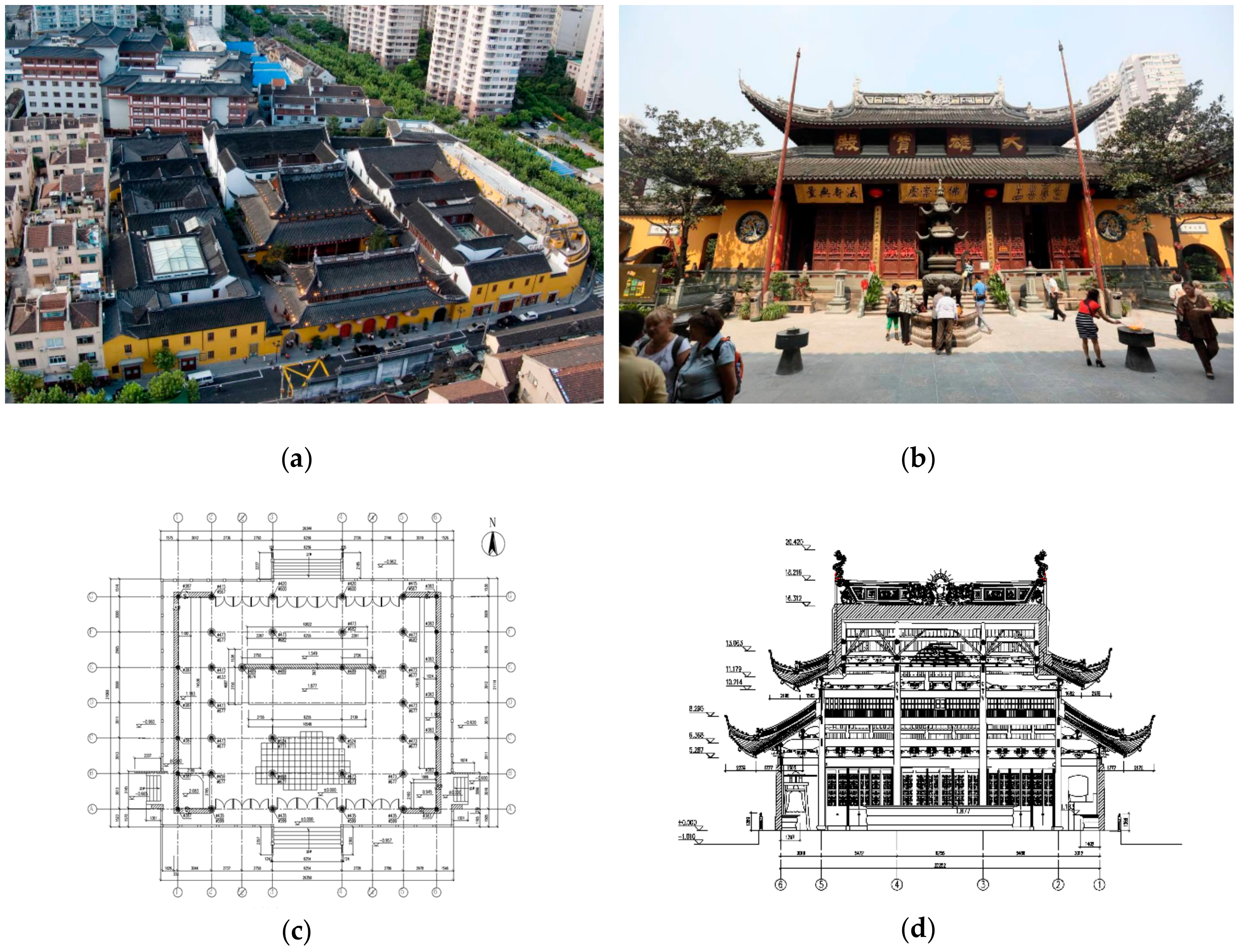
2. Structural Characteristics of the Building

The Jade Buddha Temple was initially built in 1882 in Jiangwan, Shanghai with two jade Buddha statues and was imported to Shanghai from Myanmar by sea. After the temple was destroyed during the war, the statues were preserved and moved to its current location in Anyuan Road, Shanghai. The existing Jade Buddha Temple was built from 1918 to 1928. It represents a highly valued historical and cultural temple of China [9]. Mahavira Hall is the main part of the temple and was built using the traditional Chinese timber architecture with post-and-lintel construction (Figure 1).
As a traditional Chinese timber architecture, the Mahavira Hall has the following unique characteristics (Figure 2):
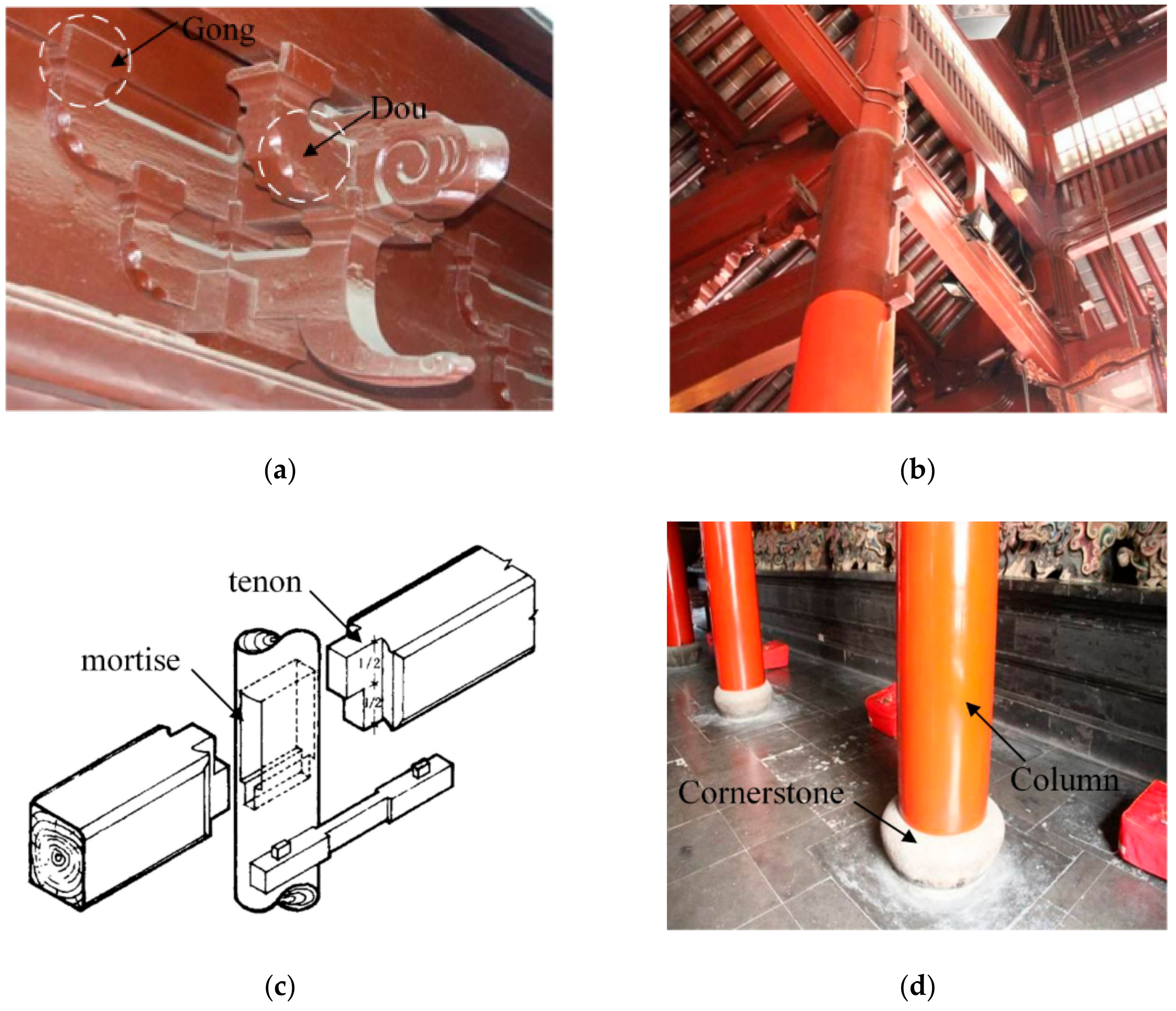
  • The Dou-Gong (bracket set) is a bracket system in Chinese buildings. Each bracket consists of a bow-shaped arm, called a Gong, and a square block of wood, called a Dou (Figure 3a). This system is placed on the top of the column to support the roof and also functions as a typical decoration.
  • Beams and columns are connected by mortise and tenon joints. This kind of connection is a slot-plug type without any metal fasteners as illustrated in Figure 3b,c.
  • The weight of the roof is transferred from the purlins to the top of the Dou-Gong, and then transferred to the beams and columns of the main frame. The columns are simply supported by cornerstones (Figure 3d).

3. Visual Inspection before Translocation

Failures are defined as events which directly or indirectly have or could have implied risk for human lives, which are mainly related to the ultimate limit state and serviceability [21]. For timber structures, the typical failure modes and causes for failures are summarized as follows [22,23]:
  • Material performance has great effects on the structural performance. For instance, low-quality joints in timber structures leads to a poor integrity and stiffness of structures, which might cause structural deformation or movement during construction or an accidental event.
  • Environmental effects often lead to the deterioration of timber structures. For instance, cracks often take place in timber structures which are exposed to moisture conditions. Damage from rot and similar effects are a slow process. Such damage is often hidden, remaining undetected for long periods of time.
  • Human errors have led to most failures. They can be divided into three categories: Errors of knowledge, errors of performance, and errors of intent. For instance, inadequate appreciation of load effects can be considered as design errors, i.e., failure to consider certain loads can cause insufficient bearing capacity of structural components.
Therefore, visual inspection, which is the preliminary step for any assessment of timber structures, was conducted to provide information about the original or historic characteristics of the structure. It also allowed for the detection of visible damage and deterioration of the members as well as the whole structure, such as decay of timbers, cracks, and so on. Colla et al. [24] summarized the most common examples of damage and deterioration to timber structures identified by visual inspection.
Considering engineering practice, a thorough visual inspection was performed before the translocation. The results of visual inspection showed that the whole building was basically intact, and the load-bearing structure was in good condition even though some timber components were deteriorated, and cracks were detected. The whole load-bearing system had characteristics of definite load conditions and a clear load transfer route. In addition, the Buddha statues were in good condition with no significant cracks or abrasions. In summary, as the preliminary step of structural assessment, visual inspection supports the feasibility of translocation and provides guidance for construction.

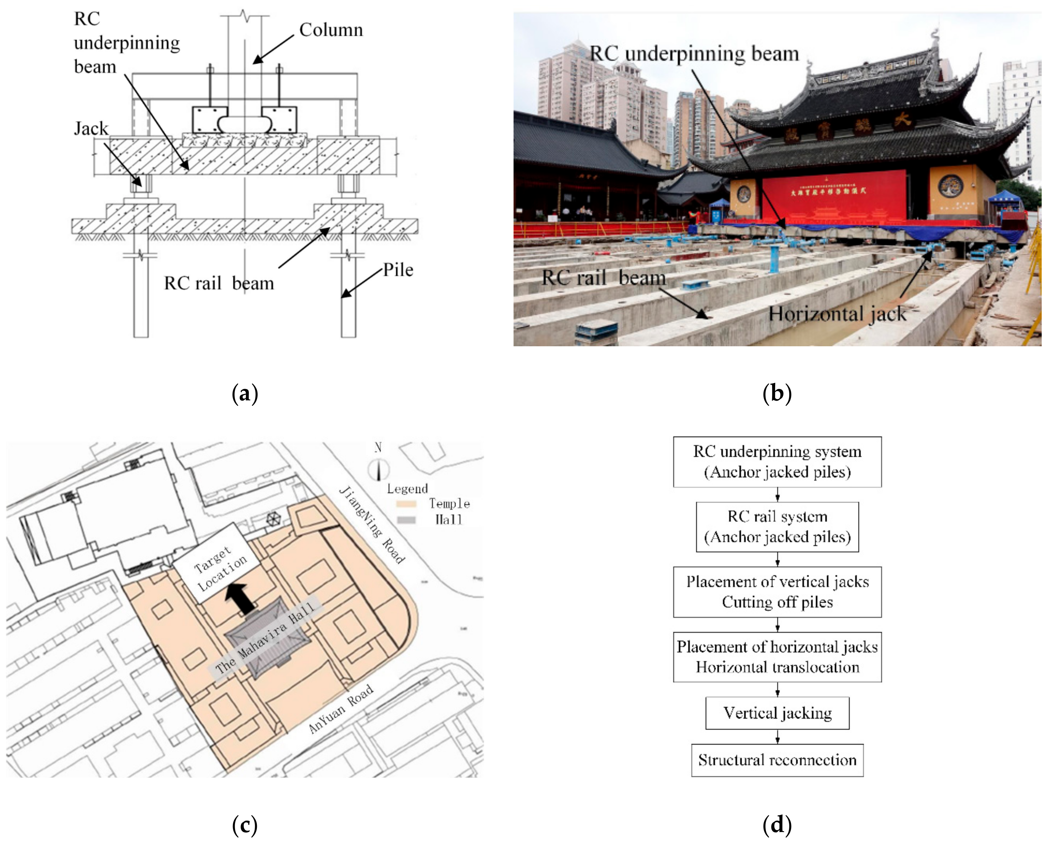
4. The Translocation Survey and Planning

The critical areas and potential risks of the structure were identified based on the structural characteristics and visual inspection of the architecture. As noted earlier, the joints of a structure are typically considered as a structure’s weakest link [4]. In the Mahavira Hall of the Jade Buddha Temple, all the timber columns are simply supported by cornerstones. These weak connections lead to poor integrity and stiffness of structure. In addition, the Buddha statues are made of clay, which are prone to deformation and even cracks during translocation. To ensure the structural safety of the Mahavira Hall and to protect the Buddha statues during translocation, increasing the structural integrity and protecting the statues must be a priority.
Considering that the building was weak in both structural integrity and stiffness, reinforced concrete underpinning joints were manufactured at the root of each column and wall and were tied by transverse reinforced concrete underpinning beams to form a horizontal frame, which provided in-plane stiffness and transferred the horizonal propelling forces. Anchor-jacked piles were pressed into the ground underneath the underpinning beams to transfer vertical loads to the foundation.
Then, the soil beneath the underpinning beams was excavated and reinforced concrete rail beams were constructed and cast with piles. To provide enough support for the rail system, anchor-jacked piles were also pressed underneath the rail beams in the transition section. After that, vertical jacks were placed between the underpinning beams and rail beams, and the pipe piles were cut off between the underpinning beams and rail beams. Hence, the vertical loads were transferred by vertical jacks to the piles (Figure 4a).
Horizontal hydraulic jacks were installed to push the building forward to the destination (Figure 4b. The translocation began on the morning of 2 September, 2017 and lasted six days. The building was moved a required 30.66 m. The translocation route is described in Figure 4c. After the building reached its final destination, it was lifted up by 1.05 m using vertical jacks and then connected with the rail beams, which provided the new foundation for the main hall. The project flowchart is illustrated in Figure 4d.

5. Structural Monitoring of Mahavira Hall During Translocation

5.1. Design Objectives of Monitoring System

As previously mentioned, several critical measures should be taken to ensure structural safety during the translocation. The following objectives, steps, and evaluation of the monitoring design, implementation, and evaluation are delineated in this paper. To guide the remedial construction accurately and to evaluate the effect of translocation quantitatively, design objectives were established, including the potential risks to the structure during the translocation. The corresponding design principles of the monitoring system are presented as follows:
  • The weak connections of the Mahavira Hall lead to poor integrity and structural stiffness. During the translocation, the structural base may have a vertical differential movement, causing the overall structure to tilt, which leads to the tilt of the columns, walls, and statues. Therefore, a monitoring system was designed to provide information relating to configuration of the overall structure and inclination angle of key structural members.
  • The Buddha statues, which are made of clay, are planned to move synchronously with the overall structure. Considering the vulnerability of the Buddha statues, a real-time monitoring system was designed to monitor the deformation of the Buddha statues, which can detect abnormal process of the translocation and ensure the safety of construction.

5.2. Design Scheme of Monitoring System

The configuration of the overall structure and the inclination angle of the columns, walls, and statues are the monitoring measurement during translocation of the Mahavira Hall. Accordingly, hydrostatic leveling (HL), inclinometers (IC), and laser displacement meters (LD) were used to gather various data. They helped to obtain a complete and reasonable overview of the problems that had to be addressed due to the complementary functions of all the instruments and the specific nature of the data gathered.

5.2.1. Vertical Differential Movement of the Structural Base

The relative vertical displacement at every point was measured by hydrostatic leveling. The positions of the hydrostatic leveling are shown in Figure 5 and were labelled as from HL-1to HL-6. The position of HL-5 was set as the reference point of all the observation points. According to the principle of deformation coordination, the relative positions of all the hydrostatic leveling were established. This made it possible to obtain the overall structure’s vertical differential movement.

5.2.2. Inclination Angle of the Vertical Members

Figure 6 shows the position of the ICs. Figure 6a shows ICs 1-12. ICs 1-2, ICs 3-4, and IC 5-12, which were placed so they could directly measure the inclination angle of the walls, Buddha platform, and columns, respectively. ICs 1-6 are biaxial inclinometers measuring the inclination angle in the X and Y direction. ICs 7-12 are uniaxial inclinometers, which can only measure the inclination angle in the X direction.

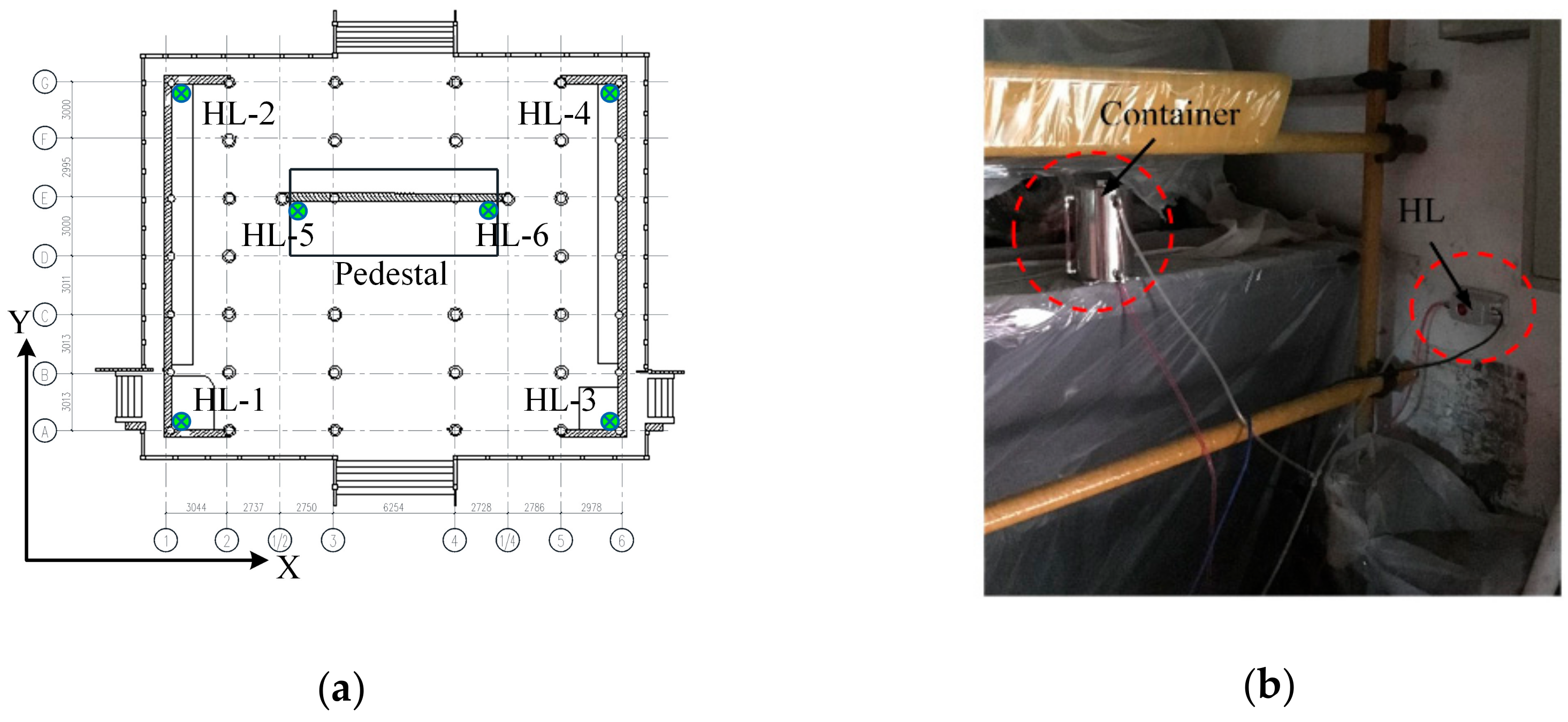
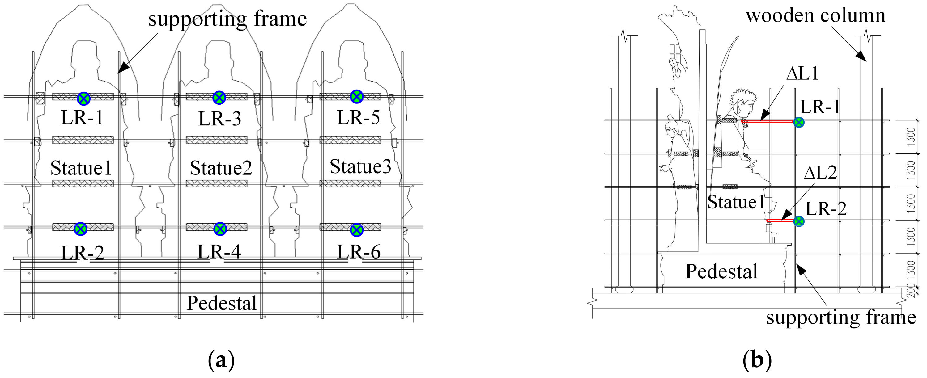
5.2.3. Inclination Angle of the Buddha Statues

Figure 7 shows LRs installed on the supporting frame of the Buddha statues and the pedestal. Figure 7a shows the position of the LRs 1–6 (two LRs per statue). Three of them (LR-1,3,5) were installed at 6.7 m above the ground, facing the top of the statues, and three of them (LR-2,4,6) were installed at 2.8 m above the ground, facing the bottom of statues. It is known that the distance between the LRs on the higher and lower position of the supporting frame is 3.9 m. As an example, Figure 7b shows the position of the LR-1 and LR-2, with the variation of distance measured by the laser range finders, recorded as Δ L 1 and Δ L 2 , the inclination angle in the Y direction of the Buddha statue 1 was calculated by dividing the difference between Δ L 1 and Δ L 2 by 3.9 m.

6. Observation Data Analysis

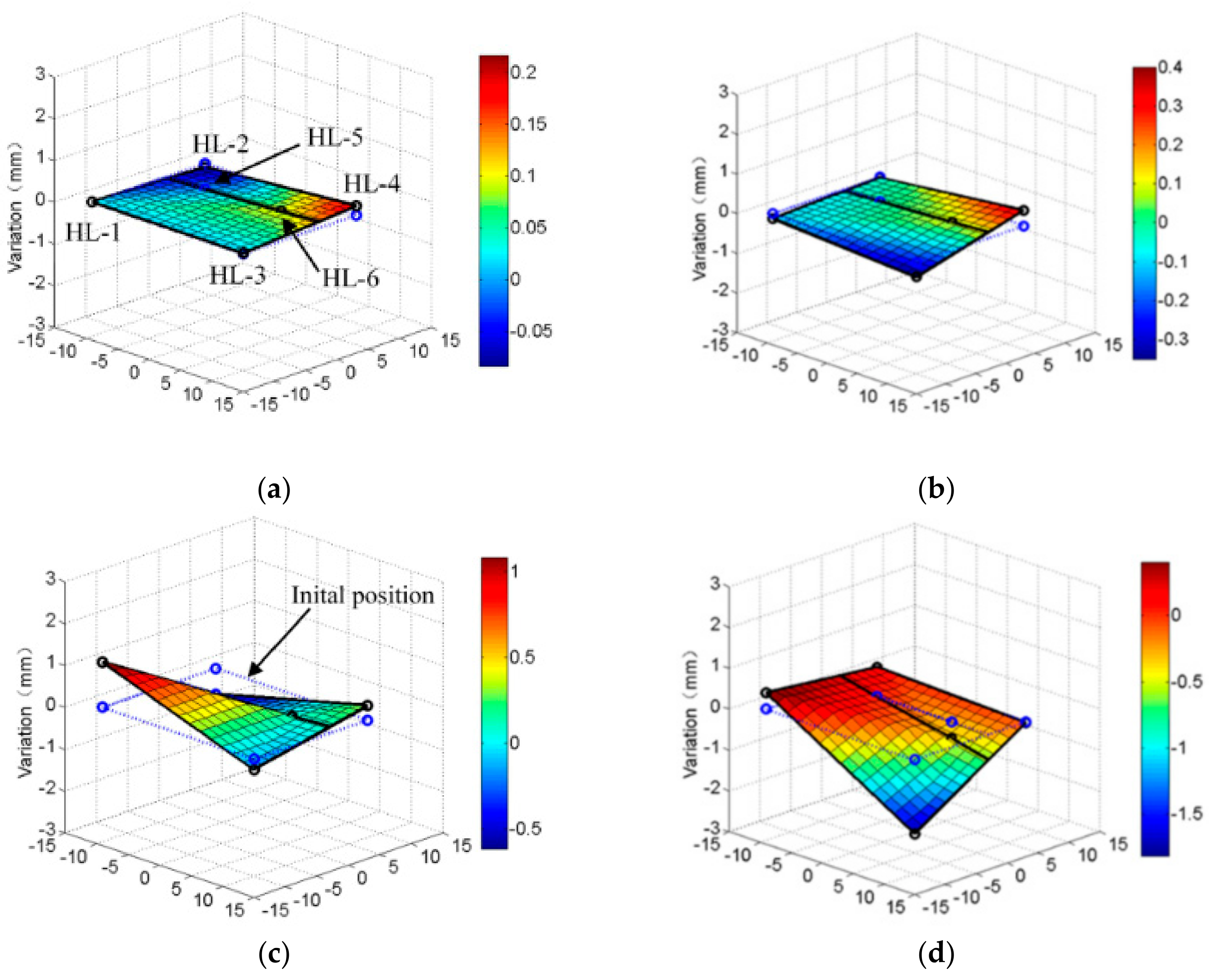
6.1. Vertical Differential Movement of Structural Base

Using the position of HL-5 as the reference point, the relative change values of other hydrostatic leveling can be plotted, as shown in Figure 8. As can be seen from Figure 8, the relative variation of vertical deformation was relatively small before the translocation, but during translocation, the variation and discreteness became significant. The relative variation of vertical deformation ranged from −0.26 mm to 0.14 mm. The maximum inclined angles of structural base in the X direction and Y direction had been calculated as 5.87 × 10 3 and 5.97 × 10 3 degree, respectively. To observe the situation of each stage, points A, B, C, and D represent a specific time point before, during, and after the translocation. The broken vertical lines mark the start and end of each stage. The points of each hydrostatic leveling were connected by a straight line representing the geometry of the structural base, and then meshed according to the condition of deformation compatibility assuming that the structural base is an elastically deformable body. As a result, Figure 9 shows a vertical differential movement of the structural base, which indicates that the overall structure was likely to tilt during the translocation.

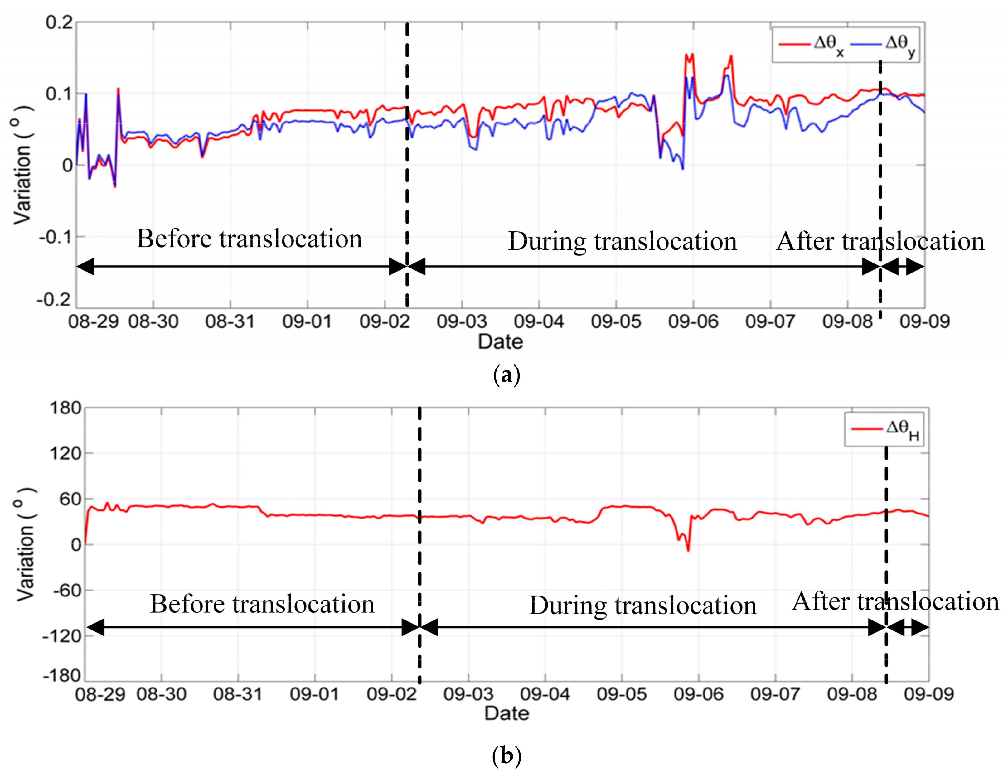
6.2. Inclination Angle of the Vertical Members

In order to describe the characteristics of data from inclinometers, the monitoring data is drawn on a boxplot. On each box, which can be seen in Figure 10 and Figure 11, the central red line in the blue box is the median and the edges of the box are the 25th and 75th percentiles, respectively. The ends of the whiskers mark the highest and lowest values of the dataset that are within 1.5 times the interquartile range of the box edges, which corresponds to 99.3 percent coverage if the data are normally distributed. The outliers are plotted individually using the red plus sign, which are outside the range of the whiskers. The spacings between the different parts of the box represents the degree of dispersion and skewness of the monitoring data.
The data variation of all the inclinometers are presented in Figure 10. Figure 10 shows that the inclination angle variation of the wall fluctuates within a range from −0.2 to 0.1 degree, and the tilting angle variation of the column fluctuates within a range from −0.4 to 0.4 degree. The number of outliers of the column is larger than that of the walls, which shows that the column is more sensitive to the translocation than the wall. To describe the variation over the time, the inclination angle variation of a column is presented in Figure 11, which shows that the variation and discreteness became larger as the number of outliers increase during the translocation.
For the biaxial inclinometers, the inclination angle in the X and Y directions can be measured as Δ θ x and Δ θ y . Then, the horizontal offset angle Δ θ H can be calculated through the mathematical relation: tan Δ θ H = tan Δ θ y / tan Δ θ x , which can represent the inclined direction of the structural member. The calculation principle is shown in Figure 12.
Taking the timber column with the biaxial inclinometer IC-5 as an example, the inclination angle of the column in the X, Y, and horizontal directions are shown in Figure 13. As can be seen from the figure, the inclination angle variations of the column in the X and Y directions almost changes simultaneously following a similar trend. Therefore, the horizontal offset angle is almost constant, which means the column is tilted in a specific direction. The fluctuations occurred during the translocation, which shows that the translocation had a significant effect on the inclination angle of the column.

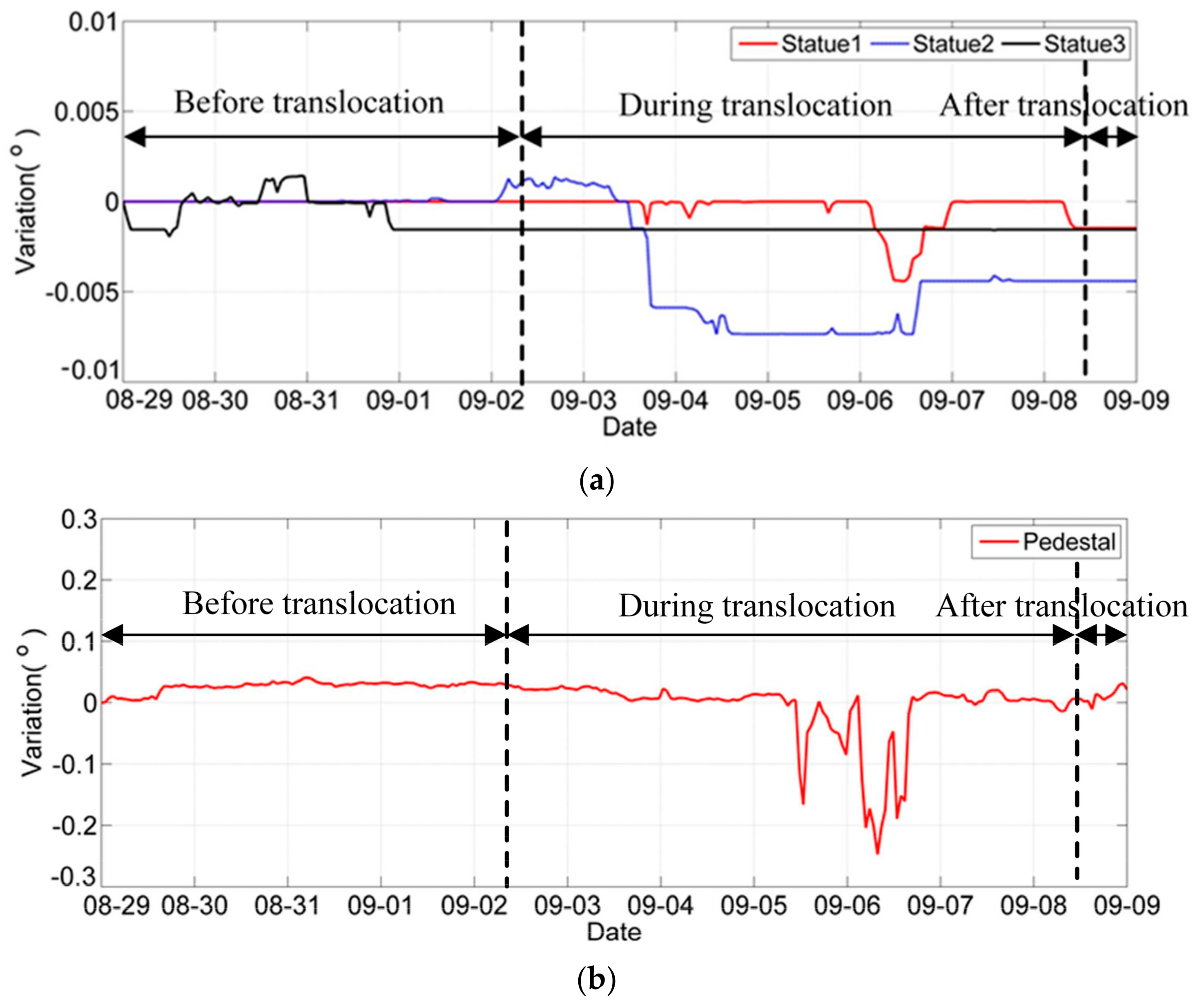
6.3. Inclination Angle of the Buddha Statues

As mentioned above, it is known that the distance between the laser range finders on the higher and lower position of the supporting frame is 3.9 m. With the variation of distance measured by the laser range finders, the inclination angle in the Y direction of the Buddha statues was calculated and recorded as Δ θ y . The inclination angle of the Buddha pedestal in the Y direction was measured by IC-1 and IC -2. As can be seen from the Figure 14, before the translocation, the variations of the inclination angles of these three statues and the pedestal were almost zero and unchanged, meaning that the whole structure had a small deformation and good stability before the translocation. However, during the translocation, especially during 5 September and 7 September, the variations of the inclination angles of these three statues and the pedestal were changed rapidly and almost in the same direction. The straightforward reasons need more research, but it was obvious that the structural uncertainty was more remarkable during the translocation, the structure was more likely to have a greater deformation and worse stability during the translocation.

7. Evaluation of Structural Safety

7.1. Evaluation Based on the Inclination Angle

According to the “Technical code for maintenance and strengthening of ancient timber buildings” (GB 50165-92) of China, the maintenance and protection of ancient architectural timber structures shall be carried out to evaluate the structural reliability by analyzing the state of the damage indexes. For beam-supported timber frames, the damage index includes: (1) The specified value of the offset of the wall is Δ > H / 150 , which converted into the critical inclination angle is 0.239 ° , while H 0 is the total height of the wall; (2) the specified value of the offset of the timber column is Δ > H / 90 , which converted into the critical inclination angle is 0.637 ° , while H is the total height of the timber column [25].
Hence, the inclination angle of walls and columns were used to evaluate the overall structural performance. In this paper, the extreme value theory (EVT) was used to determine the early warning threshold values of the inclination angle. EVT can provide an effective estimation of the tail distribution since it is primarily concerned with the quantification of a stochastic behavior of a process at usually the smallest, the largest, and the events over a threshold in a sample, rather than estimating the whole distribution of the monitoring data [26]. EVT mainly includes the block maxima method (BMM) and peaks over threshold (POT) analysis, which can be used to fit the distribution of measured values [27]. This paper adopts the BMM model and combines the probability of structural failure to draw up prewarning indicators.
The BMM model assumes the overall distribution of the inclination angle is set to an unknown distribution F x . The monitoring sequence is X 1 , X 2 , , X 11 when the monitoring value is divided into 11 blocks in days. The maximum values selected in each block consist of the sequence x m 1 , x m 2 , , x m 11 ; m is the number of the data in the block. Let X = x m i , then the maximum distribution function is:
F max x = P X x = G ξ , μ , σ x ,
where
G ξ , μ , σ x = exp 1 + ξ x μ σ 1 / ξ ξ 0 exp exp x μ σ 1 / ξ ξ = 0 .
G ξ , μ , σ x is the generalized extreme distribution function (GEV), which includes the Frechet distribution, Weibull distribution, and Gumbel distribution. ξ is a shape parameter, μ is a position parameter, and σ is a scale parameter.
The maximum likelihood estimation method was used to obtain the estimated values of the parameters ξ , μ , and σ . Assuming that the early warning threshold value of the inclination angle is x m , the probability of failure is combined and determined by the engineering conditions (taken as 5% in this paper). Thus, the estimated value of the warning value is
x ^ m = μ σ ξ 1 n l n 1 P a ξ ξ 0 μ σ l n n l n 1 P a ξ = 0 .
The critical values regulated by code and calculated early warning threshold values based on the BMM model are shown in Table 1.

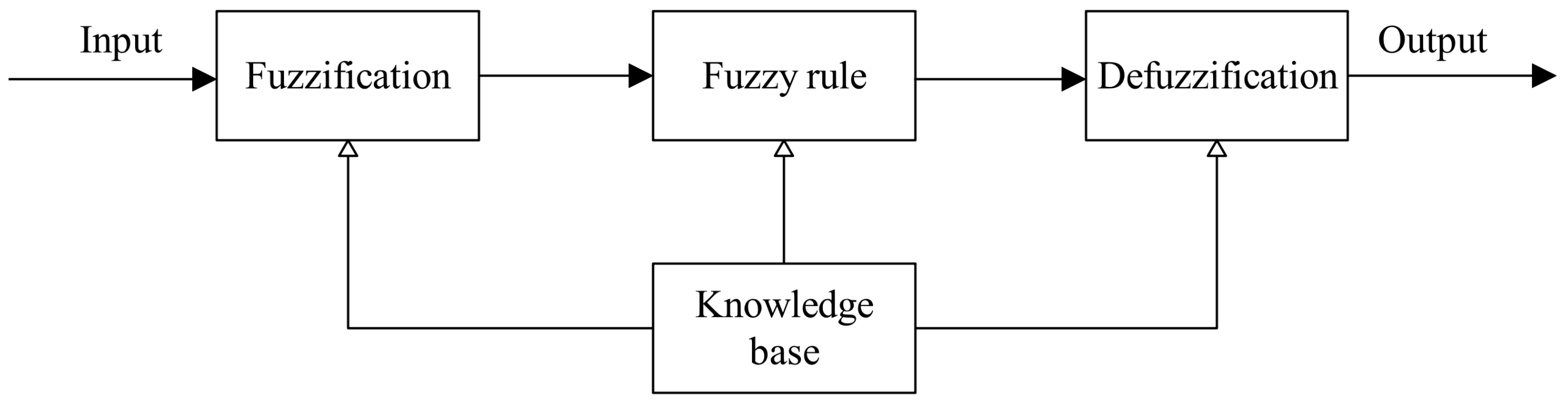
7.2. Fuzzy Logic Expert System

Fuzzy logic was derived from the fuzzy set theory studied by Zadeh in 1965, which has a myriad of applications in artificial intelligence, expert system, and control engineering. The fuzzy logic expert system, in addition to dealing with uncertainty, resembles human decision-making with its ability to draw precise solutions from ambiguous information [28].
The performance evaluation with fuzzy logic comprised three stages (Figure 15): Fuzzification of input variables and output variables using membership function; determination of fuzzy rules (“If-Then” rules) and reference method; defuzzification of output variables (performance value).

7.2.1. Fuzzification of Input Variables and Output Variables

As the first step, each input variable may be partitioned separately, and each component of input space is assumed to be independent of each other [28]. In this paper, the inclination angle of columns and walls are considered as two independent input variables. This paper assumes that zero, the early warning threshold value, and the critical value regulated by code correspond to good, fair, and poor states, respectively. These fuzzy numbers are modeled using the membership functions shown in Figure 16a,b.
To assess the variation of the structural performance, a rating between 0 and 1 was used to describes the severity of the symptom, and the output variables could represent: 0 as very good, 0.25 as good, 0.50 as fair (warning state), 0.75 as poor (dangerous state), and 1 as very poor. These fuzzy numbers were modeled using the membership functions shown in Figure 16c.

7.2.2. Fuzzy Rules and Inference Generation

By setting fuzzy control rules, which can be seen in Table 2, the relationship between input variables and output variable is established. For conservativeness reasons, it is designed that the entire structure would behave poorly if one of the input variables is poor regardless of the performance of another input variable. For example, if the wall is poor and the column is good, then the overall structure is poor.

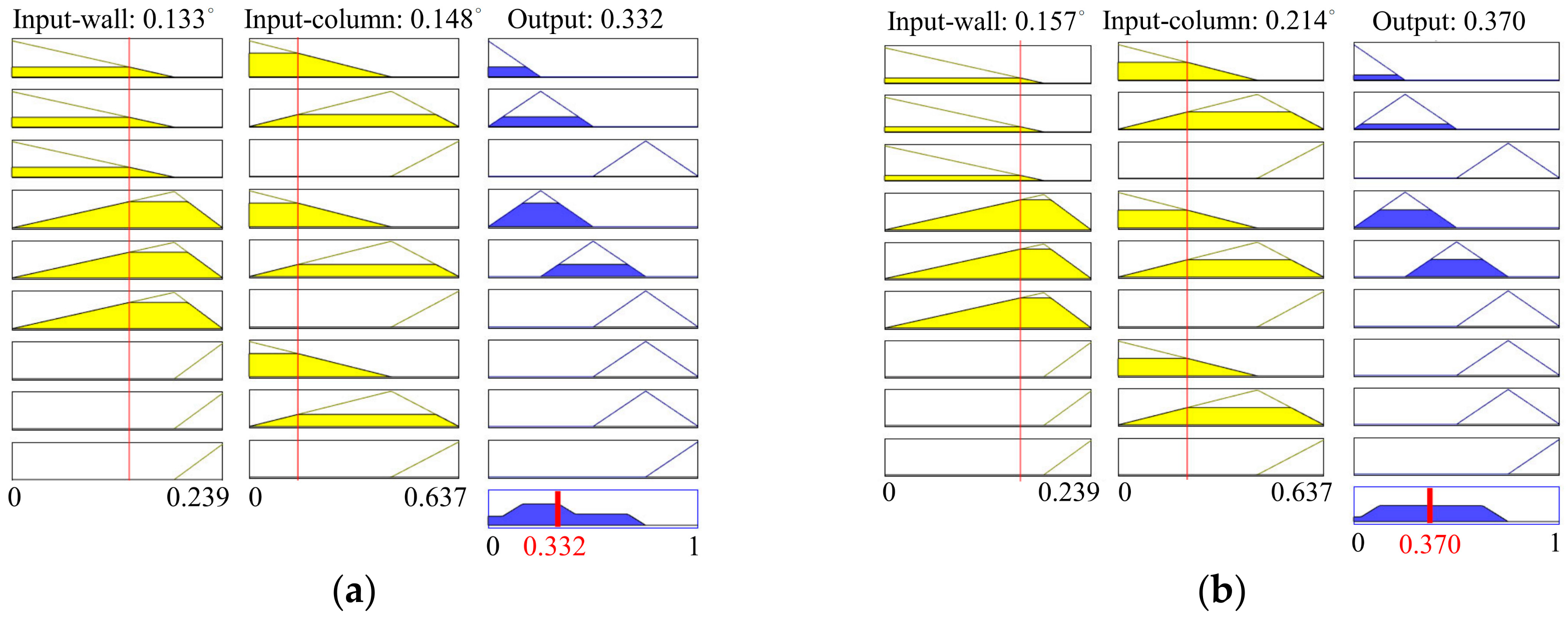
7.2.3. Calculation of Performance Value

To assess the effect of translocation on the structural performance, the monitoring data were divided into two parts: Before the translocation and during the translocation. The input variables before the translocation and during the translocation were selected by calculating the average variations of corresponding periods, which can be seen in Table 3.
The calculation of performance value was done in Matlab simulation. The fuzzy inference system adopted Mamdani system, which was introduced to create a control system by synthesizing fuzzy rules obtained from human operators [29]. Then the variation of the structural performance, i.e., the named output variable (performance value), was obtained, which can be shown in Table 3 and Figure 17. The results show that the performance value was increasing from 0.332 to 0.370 during translocation, indicating that the performance of structure was getting worse during translocation, but remained within a safe range (less than 0.50).

8. Conclusions

Structural monitoring is an efficient approach to support decisions on the best ways to preserve a historic building. Structural monitoring not only helps to evaluate the effect of the translocation on a building, but it can also achieve balance between structural safety requirements and the protection of its historic and cultural values. From the above analysis, we were able to extract the following conclusions:
  • The monitoring system designed for the translocation of the Mahavira Hall of Jade Buddha Temple can be considered as a novel first in the development of the translocation. The monitoring system can also serve as a milestone and model when developing other monitoring systems to determine the best plan for the translocation of historic buildings needing more stability and protection.
  • The analysis of monitoring data shows that during the translocation, the structural base had vertical differential movement, resulting in the inclination of the timber columns and Buddha statues. It had been proven by observing the increase in data variation and dispersion during the translocation.
  • The BMM model of extreme value theory focuses on the tail distribution, which fits well with monitoring data distribution. The calculated early warning threshold values based on the extreme value theory proved to be effective in structural performance evaluation as well.
  • The effect of translocation on the structural performance of the Mahavira Hall was evaluated using fuzzy logic. The results showed that the performance of structure was worsening during the translocation, but remained within a safe range.

Author Contributions

L.X. and W.L. conceived and supervised the monitoring project. F.Z. and R.Z. finished data curation. R.Z. developed the evaluation methodology. R.Z. prepared the original manuscript. L.X. edited the manuscript. S.X. and W.L. analyzed the data and commented the manuscript.

Funding

This research was funded by National Natural Science Foundation of China (51778490, 51878484), the Key Program of Intergovernmental International Scientific and Technological Innovation Cooperation (2016YFE0127600), and International Joint Research Laboratory of Earthquake (ILEE-IJRP-P2-P3-2017).

Conflicts of Interest

The authors declare no conflict of interest.

References

  1. Turner, B. Major Cities; Palgrave Macmillan: London, UK, 1999. [Google Scholar]
  2. Song, Y.S.; Guo, T.; Di, Z.Q.; Wei, L.W.; Wei, H. Translocation of Three Historical Buildings in Renovation of the Porcelain Tower of Nanjing. J. Perform. Constr. Facil. 2018, 32, 04017125. [Google Scholar] [CrossRef]
  3. Guo, T.; Li, A.; Wei, L.; Gu, Y. Horizontal Translocation of a High-Rise Building: Case Study. J. Perform. Constr. Facil. 2013, 27, 235–243. [Google Scholar] [CrossRef]
  4. Xu, J.; Chen, Y.; Guo, T.; Di, Z. Protection of Historic Buildings through Structural Translocation during Construction of Deep Foundation Pit. In Proceedings of the International Conference on Intelligent Computation Technology and Automation, Changsha, China, 25–26 October 2014; pp. 964–967. [Google Scholar]
  5. Fang, D.P.; Iwasaki, S.; Yu, M.H.; Shen, Q.P.; Miyamoto, Y.; Hikosaka, H. Ancient Chinese Timber Architecture. I: Experimental Study. J. Struct. Eng. 2001, 127, 1348–1357. [Google Scholar] [CrossRef]
  6. Fang, D.P.; Iwasaki, S.; Yu, M.H.; Shen, Q.P.; Miyamoto, Y.; Hikosaka, H. Ancient Chinese Timber Architecture. II: Dynamic Characteristics. J. Struct. Eng. 2001, 127, 1358–1364. [Google Scholar] [CrossRef]
  7. Branco, J.M.; Giongo, I. Special issue on “existing timber structures”. Int. J. Archit. Herit. 2018, 12, 505–506. [Google Scholar] [CrossRef]
  8. American Society of Civil Engineers. Structural Wood Research Needs. J. Struct. Eng. 1986, 112(ST9), 2155–2165. [Google Scholar]
  9. King, W.S.; Yen, J.Y.R.; Yen, Y.N.A. Joint characteristics of traditional Chinese wooden frames. Eng. Struct. 1996, 18, 635–644. [Google Scholar] [CrossRef]
  10. Guo, T.; Wu, E.; Li, A.; Wei, L.; Li, X. Integral Lifting and Seismic Isolation Retrofit of Great Hall of Nanjing Museum. J. Perform. Constr. Facil. 2012, 26, 558–566. [Google Scholar] [CrossRef]
  11. Shapira, A.; Schexnayder, C.J.; Telem, D.; Goren, Y.D. Moving a Reinforced-Concrete Building: Case Study. J. Constr. Eng. Manag. 2006, 132, 115–124. [Google Scholar]
  12. Tian, L.; Hao, J.; Wei, J.; Zheng, J. Integral lifting simulation of long-span spatial steel structures during construction. Autom. Constr. 2016, 70, 156–166. [Google Scholar] [CrossRef]
  13. Riggio, M.; D Ayala, D.; Parisi, M.A.; Tardini, C. Assessment of heritage timber structures: Re-view of standards, guidelines and procedures. J. Cult. Herit. 2018, 31, 220–235. [Google Scholar] [CrossRef]
  14. Dietsch, P.; Kreuzinger, H. Guideline on the assessment of timber structures: Summary. Eng. Struct. 2011, 33, 2983–2986. [Google Scholar] [CrossRef]
  15. Riggio, M.; Anthony, R.W.; Augelli, F.; Kasal, B.; Lechner, T.; Muller, W.; Tannert, T. In situ assessment of structural timber using non-destructive techniques. Mater. Struct. 2014, 47, 749–766. [Google Scholar] [CrossRef]
  16. De Stefano, A.; Matta, E.; Clemente, P. Structural health monitoring of historical heritage in Italy: Some relevant experiences. J. Civ. Struct. Health Monit. 2016, 6, 83–106. [Google Scholar] [CrossRef]
  17. Cigada, A.; Corradi Dell’Acqua, L.; Merlin Visconti Castiglione, B.; Scaccabarozzi, M.; Vanali, M.; Zappa, E. Structural Health Monitoring of an Historical Building: The Main Spire of the Duomo Di Milano. Int. J. Archit. Herit. 2017, 11, 501. [Google Scholar] [CrossRef]
  18. Sandak, J.; Sandak, A.; Riggio, M. Multivariate analysis of multi-sensor data for assessment of timber structures: Principles and applications. Constr. Build. Mater. 2015, 101, 1172–1180. [Google Scholar] [CrossRef]
  19. Setunge, S.; Venkatesan, S.; Ranjith, S.; Gravina, R. Fuzzy Logic Based Diagnostic Tool for Man-Agement of Timber Bridges. In Proceedings of the Fifth International Structural Engineering and Construction Conference, Las Vegas, NV, USA, 22–25 September 2009; pp. 795–804. [Google Scholar]
  20. Hathout, I. Damage Assessment and Soft Reliability Evaluation of Existing Transmission Lines. In Proceedings of the International Conference on Probabilistic Methods Applied to Power Systems, Ames, IA, USA, 12–16 September 2004; pp. 980–986. [Google Scholar]
  21. Frühwald, E.; Serrano, E.; Toratti, T.; Emilsson, A.; Thelandersson, S. Design of Safe Timber Structures—How Can We Learn from Structural Failures in Concrete, Steel and Timber? Technical Report; Lund Institute of Technology: Lund, Sweden, 2007. [Google Scholar]
  22. Hansson, E.F. Analysis of structural failures in timber structures: Typical causes for failure and failure modes. Eng. Struct. 2011, 33, 2978–2982. [Google Scholar] [CrossRef]
  23. Kaminetzky, D.; Carper, K.L. Design and Construction Failures: Lessons from Forensic Investi-gations. J. Perform. Constr. Facil. 1992, 6, 71–72. [Google Scholar] [CrossRef]
  24. Colla, C.; Gabrielli, E.; Fernandez, A.J.; Marani, F.; Rajčić, V.; Stepinac, M.; Lukomski, M.; Strojecki, M. Laboratory and On-Site Testing Activities Part 3—Historical Timber Elements. Report of SMooHS European FP7 Project. Available online: https://www.bib.irb.hr/576698?rad=576698 (accessed on 12 February 2012).
  25. Sichuan Institute of Building Research. Technical Code for Maintenance and Strengthening of Ancient Timber Buildings (GB 50165—50192); China Machine Press: Beijing, China, 1993. [Google Scholar]
  26. Hao, J.; Bathke, A.; Skees, J.R. Modeling the Tail Distribution and Ratemaking: An Application of Extreme Value Theory. In Proceedings of the American Agricultural Economics Association Annual Meeting, Providence, RI, USA, 24–27 July 2005. No. 19190. [Google Scholar]
  27. Ferreira, A.; Haan, L.D. On the block maxima method in extreme value theory: PWM estimators. Ann. Stat. 2015, 43, 276–298. [Google Scholar] [CrossRef] [Green Version]
  28. Çelikyilmaz, A.; Türksen, I.B. Modeling Uncertainty with Fuzzy Logic—With Recent Theory and Applications; Springer: Berlin/Heidelberg, Germany, 2009. [Google Scholar]
  29. Mamdani, E.H.; Assilian, S. An experiment in linguistic synthesis with a fuzzy logic controller. Int. J. Man Mach. Stud. 1975, 7, 1–13. [Google Scholar] [CrossRef]
Figure 1. The Jade Buddha Temple: (a) Layout of the Jade Buddha Temple; (b) the Mahavira Hall; (c) layout of the Mahavira Hall; (d) an elevated view of the Mahavira Hall.
Sustainability 11 05477 g001
Figure 2. Timber frame of the Mahavira Hall.
Sustainability 11 05477 g002
Figure 3. Local structure of the Mahavira Hall: (a) Dou-Gong; (b) beams and columns; (c) mortise-tenon joints; (d) cornerstone.
Sustainability 11 05477 g003
Figure 4. Translocation of the Mahavira Hall: (a) The underpinning system and rail system; (b) horizontal hydraulic jack and underlying rail beam; (c) translocation route; (d) executive process shown as flowchart of the project.
Sustainability 11 05477 g004
Figure 5. Hydrostatic leveling (HL): (a) HL layout; (b) HL and container.
Sustainability 11 05477 g005
Figure 6. Inclinometers (ICs): (a) An IC layout showing the location of 12 ICs; (b) An IC fixed on a column.
Sustainability 11 05477 g006
Figure 7. Laser range finder (LR) layout: (a) Front view; (b) Side view.
Sustainability 11 05477 g007
Figure 8. Relative variation of vertical deformation (mm). A, B, C, and D points represent a certain time during the stages of translocation: (A) Before the translocation; (B) beginning of the translocation; (C) during the translocation; (D) after the translocation.
Sustainability 11 05477 g008
Figure 9. Vertical deformation of the overall structure (mm): (a) Before the translocation; (b) beginning of the translocation; (c) during the translocation; (d) after the translocation.
Sustainability 11 05477 g009
Figure 10. Inclination angle variation of walls and columns.
Sustainability 11 05477 g010
Figure 11. Inclination angle variation of a column (IC-9).
Sustainability 11 05477 g011
Figure 12. Calculation principle of the horizontal offset angle.
Sustainability 11 05477 g012
Figure 13. Inclination angle of inclinometer IC-5(°): (a) Inclination angle in the X and Y directions; (b) horizontal offset angle in the horizontal direction.
Sustainability 11 05477 g013
Figure 14. Inclination angle in the Y direction (°): (a) Inclination angle of Buddha statues; (b) inclination angle of pedestal.
Sustainability 11 05477 g014
Figure 15. Basic architecture of a fuzzy logic expert system.
Sustainability 11 05477 g015
Figure 16. Membership function of variables: (a) Membership function of input variable for wall; (b) membership function of input variable for column; (c) membership function of output variable.
Sustainability 11 05477 g016
Figure 17. Calculation of performance value using Matlab: (a) Before the translocation; (b) during the translocation.
Sustainability 11 05477 g017
Table 1. Limit value and prewarning value.
ItemEarly Warning Threshold Value (°) (BMM)Critical Value (°) (Code)
Inclination angle of the wall0.1840.239
Inclination angle of the column0.4310.637
Table 2. Fuzzy control rules.
Input Variable (wall)GoodFairPoor
Input Variable (column)
GoodVery goodGoodPoor
FairGoodFairPoor
PoorPoorPoorVery poor
Table 3. Input and output variables.
ItemBefore TranslocationDuring Translocation
Input variableInclination angle of wall (°)0.1330.157
Inclination angle of columns (°)0.1480.214
Output variable0.3320.370

