1. Introduction
Any analysis of the sustainability of a technological process must start with a study on energy consumption. The energy consumption varies during one technological process of manufacturing, or from one technological process to another, and considerably influences the processing from a sustainability point of view.
In recent years, the concept of sustainability has attracted the attention of many researchers, the world trying to reach the level of sustainable processing, or “green manufacturing”, as the term came to be known in recent years [
1,
2], and “sustainable processing” has been defined in many ways. The most well-known definition refers to the limitation imposed by the state of technology and social organization upon the ability of the environment to meet the needs of the present and the future [
3,
4].
A large part of the total cost of processing a product is represented by the energy consumption. The energy consumption for the realization of a product represents an important aspect that should be taken into account when analyzing the sustainability of a technological process [
4,
5,
6]. In the automotive industry, electricity consumption, for example, represents about 50% of total energy consumption, and generates large quantities of greenhouse gases that cause air pollution [
5,
7,
8,
9]. Nearly 35% of global electricity production is used for processing activities which are responsible for nearly 20% of global carbon emissions [
6]. Thus, each company should ensure minimal energy consumption and reuse/recycling possibilities.
In other words, the impact on the environment can be assessed on the basis of the energy consumption which corresponds to greenhouse gas (GHG) emissions, waste streams and water consumption [
10,
11,
12]. The energy consumption during a manufacturing process has three different components: Energy during processing; the energy from the standby time of the machine tool; the energy during the set-up period [
5]. Mainly in order to reduce energy consumption during a manufacturing process, two directions have to be considered, namely: The performance of the machine tool, and the optimization of the processing parameters [
13,
14,
15,
16].
The investment for the change or modernization of the existing machine tool is too large, therefore, in general, to reduce energy consumption, those involved should resort to the attempt to reduce energy consumption by optimizing the way the product is made, in other words, there should be taken into account all the parameters that are used when optimizing a manufacturing process [
8,
17,
18,
19].
In order to optimize an ordinary manufacturing process, the four parts of it should be taken into account, namely: Machine tools, auxiliary equipment, tools, material delivery/supply. A more detailed analysis is required because of the different processing capabilities of machine tools, the different functionalities of the auxiliary equipment and the various tools that have different influences on the energy consumption at this level. Saving energy at this level includes an online optimization system of working parameters which allows a real-time monitoring of energy consumption [
4].
Different relations between processing parameters and energy consumption were studied, and there was established that only 25% of the energy consumption is related to the processing itself, and more than 40% of the energy quantity is consumed during the idle period of the machine tools [
6,
20,
21,
22,
23]. The power consumed by a machine tool depends on several factors, namely: Rotation of the main shaft, circulation of the coolant, the processing itself, idling, start, stop, emergency stop, axis movement, cooling pump, etc. [
4].
In other words, to reduce energy consumption and create a sustainable technological process, there should be implemented a system that must take into account the following:
Identifying a smarter method for selecting the different sensors;
Carrying out statistical analyses for the discovery of indicators necessary for energy consumption;
Designing an advanced control system for Computer Numeric Control (CNC) in order to ensure robust, intelligent and adaptive control in an efficient manner from an energy point of view;
Making a robust database that includes materials, tools, etc., to optimize the operations, in the sense of reducing the energetic consumptions [
4].
Thus, a distribution of energy consumption during a manufacturing process is shown in
Table 1.
A manufacturing process usually takes a long time, and gives a lot of information that helps in decision making. It plays an important role, being a link between design and manufacturing. Any manufacturing process must be studied: Micro-plan, which refers to parameter setting, tools, cutting liquids, energy consumed, processing time, etc. and macro-plan, which refers to the relationships between product characteristics. Thus, the manufacturing process is based on the connection between design, material and processing parameters [
4].
Transition fittings are characterized by high complexity, which also implies a technological process, complicated because they are elements of connection between rigid elements, such as metal pipes, and pipes made of flexible materials, of the type of polyethylene.
At present, the specialized literature presents very little information related to the analysis of the constructive variants of the transition fittings. Thus, a series of data through the possible constructive variants for transition type fittings can be consulted in some patents [
24,
25]. In this context, the research presented in the paper represents a novelty in the field, and may be a starting point for a more detailed analysis for this type of parts.
Considering these aspects, in this paper, the technological processes of manufacturing the different models of transition type fittings existing from the point of view of sustainability will be pursued, taking into account their geometric form, material, technologicality, technological process of manufacturing and their functional role.
Thus, four existing transition type fittings were analyzed, and following the sustainability analysis for them, there was proposed a model of transition type fitting with a geometric shape that fulfills the same functional role, under the same conditions, but which involves lower costs, lower energy consumption, and implicitly a reduced impact upon the environment.
2. Materials and Methods
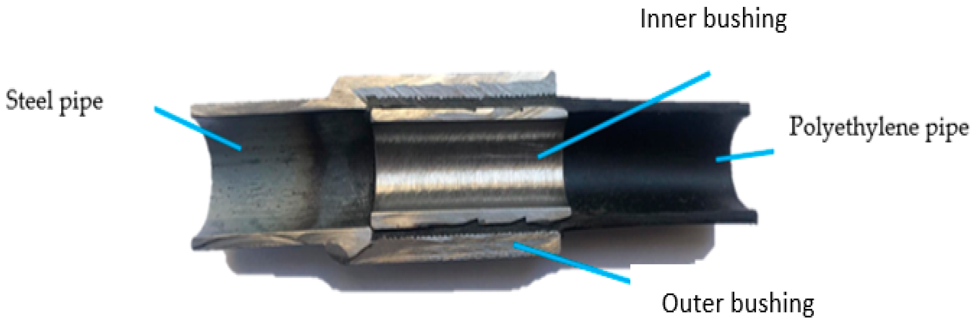
Transition type fittings are components often used in the transport facilities of fluids, and allow the passage from a plastic pipe to a metal pipe. For the construction of a transitional fitting type, as durable as possible, between the high density polyethylene pipe and the metal network, the components shown in
Figure 1 and respectively,
Table 2, are used.
Transition type fittings are obtained by assembling two materials with completely different properties and compositions, namely steel and plastics. Due to the different properties of the two components, the produced assembly will have resistance to shock, high temperatures, different pressures, and thus it is important as to their process of assembling, so as to ensure a good functionality together. Due to the different properties and behavioral differences in the same conditions of the two types of materials, to ensure a good functionality of the fitting of transition, there should be taken into account the assembly that is based on the geometrical form of the components.
For assembly, the outer bush is pre-heated or the inner bush is cooled, and thus occurs a radial expansion of the contact surfaces due to the expansion or contraction, as follows:
Polyethylene (PE) pipe is inside the outer bush and the inner bush is introduced by hot pressing, the steel pipe being welded to the inner bush.
PE pipe is inside the outer bush, and the inner bush is introduced by hot pressing, then the steel pipe is inserted which will subsequently be welded to the outer bush.
As for the part of plastic material of the transition fitting, it is made of polyethylene, PE 100 SDR11, which is the most used material for making pipes for gas and water transport, being a thermoplastic material. These types of pipes can be “injection molded” and then recycled, thus having a strong point in sustainability. The metallic part of the transition type fitting is made of a steel of construction S235JR, EN 10025-2, respectively, a steel for pipes L360GA SR EN 10208.
In order to carry out the sustainability study for the transition type fittings, an analysis was realized for four existing transition type fittings, but a new constructive version to these was proposed which would allow a high sustainability of the process of manufacturing such a type of product.
Figure 2 shows the data that was taken into account in the sustainability study for the existing transition fittings and for the proposed one, so as to obtain a sustainable variant from the point of view of the properties of the landmark, manufacturing processes, fabrication process parameters and energy consumption. The choice of the four types of transitional type fittings was made, considering that at present, these are most often used as connecting elements between a steel pipe and a polyethylene pipe. Thus, a sustainability analysis was initially carried out for four types of existing transition type fittings, and because of these results obtained, a new more sustainable type of transition type fittings was designed. In order to obtain an improved version of the transition fitting, it must meet the sustainability criterion, so it was necessary to impose a series of technological, economic but also environmental pollution objectives that the new improved version should fulfill.
3. Results and Discussion
In order to carry out the sustainability analysis of the different types of transition fittings, produced by different manufacturers, the research started from a sustainability study of the processing mode for each assembly landmark. From the point of view of processing, outer bush respectively inner bush, they contain many processing operations, and under these conditions there has been performed an analysis of the sustainability of the manufacturing process for these bushings, but also for the metallic pipe.
For the analysis of the process of processing each component of the transition fittings, the Ifind application offered by Sandvik Coromant (Sandviken, Gävleborgs Iän, Sweden) was used. This application allows us to obtain some information related to the processing cost and the processing time of each part. To be possible to obtain this kind of thing, these results were used as input data: Product design, product material, type of cutting tool used in processing, optimal durability of the cutting tool. Also, the application allowed the obtaining of some intermediate results relating to:
- ‒
Cost per tool, %;
- ‒
Cost per insert, %
- ‒
Machine tool cost, %
All these data were used to determine the cost of manufacturing for each type of transition fitting, and based on this, a sustainability analysis was performed for the entire process of obtaining the transition fittings.
3.1. Sustainability Analysis of the Process of Obtaining the Outer Bushing
In the first stage, a sustainability analysis was carried out for the process of manufacturing the four types of outer bushings used in the construction of the four types of transition type fittings,
Figure 3.
When making the outer bushings, there was observed that it is difficult to process the inner surface of the bush, so at the level of this processing, a comparative analysis of sustainability was made for the technological process of obtaining this surface.
In order to obtain the sustainability analysis, a technical-economic analysis of the processed landmarks was initially carried out, and for this purpose, the application I find which was offered by the Sandvik Coromant firm was used. The data obtained using this application, for the four types of outer bushings, are presented in
Table 3.
The presence of a surface profiled with a complex and variable geometry on the Type 3 bushing involves high processing costs, a long processing time and tool adjustment, precisely because the manufacturing is inside, and there are variable diameters, on both cylindrical and conical inner portions.
Thus, the Type 1 and Type 2 bushings represent an optimization of the Type 3 bushing, relating to the same surface with processing problems, namely the inner surface of the bush. The variation of diameters is kept because this aspect helps a lot in the correct fulfillment of the functional role of the assembly, but the geometry is a regular one, which is why the processing time will be shorter, thus the energy consumption lower.
Model 1 differs from Model 2 through the number of channels inside, located in the heavy access area; in this sense the Model 1 having only three channels, and the Model 2 having four channels in the hard access area. Given that the functional role is fulfilled by both under the same conditions, Model 1 is considered more sustainable.
The Type 4 has eliminated the variations in diameter inside the bush, trying to determine reducing the number of processing. The model has a threaded surface inside on a length of 40 mm, which ensures a good fixation of the PE pipe, and reduces the time for adjusting the tools, in the case that the combined tools are not used for the interior processing of the other three models. The threading involves at least three passes, this leading to the longest processing time, high costs, high energy consumption, therefore eliminating the variation of diameters, and adding the thread does not make the model neither more sustainable, nor better in terms of functionally referring to the other models.
In order to carry out a sustainability analysis of the technological process for obtaining the outer rings, the data presented in
Table 3 were taken into account, as well as the energy consumption necessary to obtain this type of bushing.
This resulted in a total cost for each type of outer bushing.
An evolution of the sustainability of the manufacturing process for the four types of outer bushing is presented in
Figure 4. From the analysis of the sustainability evolutions presented in
Figure 4, there can be observed that the outer bush, sustainable from the point of view of the processing, is of Type 1. In order to achieve an improved version of the outer bush from a sustainable point of view, there will have to be a start from the Type 1 outer bush.
3.2. Sustainability Analysis of the Process of Obtaining the Inner Bushing
In the second stage, a sustainability analysis was carried out for the process of manufacturing the four types of known inner bushings used to obtain the transition fittings,
Figure 5.
The inner bush of the transitional fittings has a profiled surface which should allow a very good fixing of the PE pipe in the inner bush. Thus, the fixing of the PE pipe in the inner bush is made by the differences of diameters that allow the pipe, which is malleable, to take inside itself the form that is conjugated of the outer surface of the inner bush.
From the analysis of the constructive form of the inner bushings, there was observed that it is difficult to process the outer surface of the bush, so at the level of this processing, a comparative analysis of sustainability was made for the technological process of obtaining this surface.
In order to obtain the sustainability analysis, a technical-economic analysis of the processed landmarks was initially carried out, and for this purpose, the application which I find offered by the Sandvik Coromant firm was used. The data obtained using this application, for the four types of inner bushing, are presented in
Table 4.
The bushings by Types 2 and 3 have minimum variations of diameters, the smooth surface predominates in a fairly large proportion, but their processing by pressing with a radius punch is expensive in terms of the necessary equipment.
The Type 1 bush ensures a good fixing by outlining the outer surface, the conicity of the end ensures a good orientation, and from a cost point of view, it is a favorable model with regard to Types 2 and 3. The Type 4 bush is similar to the Type 1 by preserving the conicity that ensures a good orientation of the PE pipe, and by profiling the outer surface, which helps in a good fixing, but the profile of the surface is simpler; it is outward, which implies a lower volume of work, time of processing and adjustment reduced.
In order to carry out a sustainability analysis of the technological process of obtaining the inner rings, the data presented in
Table 4 were taken into account, but also the energy consumption needed to obtain this type of bushing, and thus resulted a total cost, according to which it was established a total cost of processing each type of inner bushing.
In terms of processing time, Types 2 and 3 of inner bushing are the most sustainable, and an evolution of the sustainability of the manufacturing process for the four types of inner bushing is show in
Figure 6.
Therefore, in order to achieve a model that is the best choice from a sustainable point of view, the model of the bushing 4 will be considered, taking into account the conicity for orientation and the variation of the diameters for fixing, which can be optimized. Also in the sustainability analysis, there was taken into account the existing material resources that help to achieve the new landmark, trying to reduce costs.
3.3. Sustainability Analysis of the Process of Obtaining Steel Pipes
The steel pipe is the same in the case of the first three types, and in the case of the Type 4 of the transition type fitting, the pipe shows an inner turning,
Figure 7, which involves an energy consumption, an additional cost and extra working time, but of a small value.
The sustainability analysis of the process for obtaining steel pipes was performed by applying a technical-economic analysis and using the Ifind application offered by the Sandvik Coromant firm. The data obtained using this application, for the four types of steel pipes, are presented in
Table 5.
In order to carry out a sustainability analysis of the technological process of obtaining the inner rings, the data presented in
Table 5 were taken into account, but also the energy consumption needed to obtain this type of bushing, thus resulting in a total cost, depending upon which a total cost of processing each type of steel pipe was established.
From the point of view of the processing time for the four types of pipes, there was observed that the pipe used in the case of transition fittings of types 1, 2 and 3 is the most sustainable, and an evolution of the sustainability of the manufacturing process for the four types of pipes is shown in
Figure 8.
From the analysis of the data presented in
Figure 9, there was observed that for the development of an improved model of transition type fittings from a sustainable point of view, it is necessary to use the model of steel pipe used for transition type fittings of types 1, 2 and 3, respectively.
In order to make the fittings, the PE pipe is deformed, and takes the form conjugated of the inner surface of the outer bush and the outer surface of the inner bush. Thus, an improvement from a sustainable point of view cannot be made in the processing of the PE pipe, but only in the profiles of the surfaces corresponding to the outer bush and the inner bush.
Regarding the assembly of the components of the transitional fittings in the case of the first type of transitional fitting, the steel pipe is welded to the inner bush, and in the case of the other three types of transitional fittings, the steel pipe is welded to the outer bush.
In practice, there has been found that welding on the outer bush offers better strength, the welding cord being larger in diameter.
By summing the processing times and the costs related to the execution of each type of transition fitting, the data presented in
Table 6 were obtained.
3.4. Sustainability Analysis of the Process of Obtaining the New Type of Transition Type Fitting
From the sustainability analysis, presented above, of the four types of transition fittings, there was found that it is necessary to create a simplified transition fitting model from the point of view of geometry, but operating under the same conditions. Thus, the inner processing on the outer bush and the outer processing on the inner bush were reduced, and the steel pipe reference was kept the same as the one used for types 1, 2 and 3 of the transitional fittings. Thus, there was created a better model of transitional fittings in terms of sustainability, with less processing, less energy consumption, fewer tools, reduced working time, thus lower costs and reduced pollution.
The new type of transition fitting was created by 3D modeling the components using the CATIA V5-6R2013 software.
When designing the outer bush of the new type of transitional fitting, there was taken into account the model which was found to be the most sustainable from the point of view of the manufacturing process, namely the Type 1 model, to which improvements were made. Thus, there were kept the differences in diameter on the inner surface of the bush, the channels ensuring a good fixing, but their number was reduced to a minimum, two channels that will ensure the same functionality under the same conditions.
The processing of the channels on the inside of the outer bush can also be hard in terms of the access and adjustment of the tools, but the simple geometry of the channels and their reduced number to a minimum make the processing and adjustment time, the cost and the energy consumption, to be reduced, taking into account the main aspect, namely, the reduction of the amount of processing. Regarding the geometry of the surfaces for the new type of outer bush, this is shown in
Figure 9.
The design of the constructive shape of the inner bush, for the new type of transitional fitting, was done taking into account the type of bush that proved to be the most sustainable from the point of view of the manufacturing process, and the model of the inner bush that enters in the structure of Type 4 of transition fitting, which has been improved.
When designing the geometric shape of the new type of inner bush, there were kept the difference in diameters that ensure a good tightening, the conicity that ensures a good orientation, and the processing of a channel that offers a place of deformation to the PE pipe, ensuring its fixation.
The number of channels for fastening was also reduced to this case, with only one channel being made, which by its simple geometric shape and by the position on the inner bush reported to the outer bush, ensures a good functionality of the landmark in the same conditions in which the types of transition fittings presented previously also work.
Thus, the new model by the simple geometry of the fixing channel, by reducing the number of processing while maintaining the conicity and the diameter difference, is a sustainable model that requires less time for processing and the adjustment of tools, lower costs, less energy consumption, and at the same time does not adversely affect the functionality of the landmark.
In order to make the new geometric shape for the steel pipe, the same geometry and dimensions were used as for the first three types of transition fittings, and the new improved outer and inner bush models which were made do not require the existence of an additional machined surface on the steel pipe as is the case for Type 4 transitional fitting. The processing required for steel pipes is low, and thus the working time and energy consumption are reduced to a minimum.
The PE pipe is deformed, and will take on the outside, the conjugated form of the inner surface of the outer bush, and on the inside the conjugated form of the outer surface of the inner bush.
Regarding the way of assembling the new type of transitional fitting, the welding of the outer bush to the steel pipe was chosen, and by making the welding cord on a larger diameter, it will obtain a superior mechanical strength of the entire structure for the new type of transition fitting.
In order to carry out the sustainability analysis of the new type of transition fitting, a technical-economic analysis was carried out on the processed parts (outer bush, inner bush, steel pipe) and for this purpose, the Ifind application offered by the Sandvik Coromant firm was used.
Following the sustainability analysis, it was established that for the new transition model, the following data were obtained:
By modifying the geometric shape of the outer bush, the processing time was reduced from 6.74 s to 6.53 s;
For the inner bush the processing time has been reduced from 9.45 s to 9.03 s;
To the processing of the used steel pipe, the same processing time was kept as in the case of the steel pipe used in the manufacture of the first three types of transition fittings, namely 32.42 s.
Besides reducing the processing time, the cost for the tools needed for processing was reduced, the adjustment time was reduced, the processing was less and simpler, and consequently the energy consumption was reduced.
Following the sustainability analysis for the improved model of transition fitting, there were obtained the time required to achieve it and the cost required for processing. The data obtained for the new type of transition fitting proposed in comparison with the other four types of transition fitting are presented in
Table 7 respectively
Figure 10.
Regarding the processing time of the new type of transition fitting, it was reduced from 51.02 s, the most sustainable solution available, for Type 2 of transition fitting, to 47.98 s, the time corresponding to the proposed variant. Thus, a reduction of the processing time was realized for the realization of a transition type fitting in the proposed version, with approximately 5.96%.
As for the cost of processing the new type of transition fittings, it was reduced from 0.77 Euros, the most sustainable existing solution (Type 1 of transition fittings), to 0.20 Euros, the cost of processing according to the proposed variant for transitional fitting. Thus, if the new type of transition fittings will be manufactured, a considerable reduction of the processing costs is obtained, and a comparison between the cost of processing the new type of transition fittings and the other four types of transition fittings is presented in
Figure 11.
3.5. Analysis with the Finite Element Method of the New Type of Transition Type Fitting
The proposed constructive changes for the new type of transition type fitting also determine a change in its mechanical strength. Thus, an analysis by the finite element method of the proposed variant of transition type fitting was imposed. In order to carry out the analysis by the finite elements method, the proposed variant of transition type fitting was modeled and assembled in CATIA V5-6R2013.
Abaqus-Standard software was used to validate the new model. The four types of existing transition type fittings are approved to operate at a pressure of four bars. Of the four types of existing transition type fittings, Type 1 has the lowest processing cost. The lower cost of the existing fittings is that of the Type 1 fitting, and this is justified by the fact that it has the simplest geometry of the inner bushing from the point of view of processing, and the geometry of the outer bushing is comparable to the other outer bushings used in the manufacture, to other transition type fittings. Thus, if the proposed model resists a force close to the force resisted by the other four transition fittings, then the proposed model can be used under the same conditions with the other four types that are approved in terms of the mechanical strength of the assembly.
In the conditions in which the new type of transition type fitting behaves appropriately from the point of view of the traction stress, there can be proceeded to the next step which is considering, namely the approval of the new model by good functionality at four bar pressure. An analysis using the finite element method of tensile stress was performed for the proposed model, and all type of transition fitting. To perform the modeling by the finite elements method for all the types of transition fittings, the PE pipe was embedded, and at the opposite end represented by the steel pipe was applied a load, as shown in
Figure 12. To the plastic material of the pipe, there was assigned the allowable tension σ
max = 185 MPa.
Following the application of the finite element method, force variation diagrams were obtained according to the displacement for both the four types of existing transition fittings (
Figure 13 for Type 1 fitting,
Figure 14 for Type 2 fitting,
Figure 15 for fitting of Type 3,
Figure 16 for fitting of type 4) and for the proposed model of transition type fitting,
Figure 17.
For all types of transition type fittings, it was sought to determine the force to which the assembly cedes following request at traction. From the analysis of the values of the forces, the tensions in the material for the four types of transition existing, but also for the proposed one, it was observed that the best behaves at requesting at traction the fitting by Type 1 and the proposed fitting. In these conditions, the analysis of the operating behavior of the studied transition fittings was performed only for the Type 1 transition fitting, respectively for the Type 2 transition fitting.
In the case of Type 1 of transition type fitting, the tension reaches a maximum value of 318 MPa in the area of the welding cord between the steel pipe and the inner bushing, because the steel does not give in, and the PE pipe gives in to the force of 28,894.9 N. After the tension reaches the maximum value at which the assembly yields, the force decreases with the constriction of the PE pipe in the hazardous area.
The analysis carried out using the finite element method for the proposed transition model showed that the maximum tension reaches a value of 231 MPa, when the flow limit of the plastic material is exceeded, and the PE pipe yields to the force of 25,873.9 N. After this maximum point of tension at which the assembly fails, the force decreases with the constriction of the PE pipe in the dangerous area, near the channel from the inner bush. The force at which the assembly yields the transition type fitting in the proposed version is very high, approximately 25,800 N, which demonstrates the mechanical strength required for the new transition type fitting model improved in terms of sustainability.
By comparing the results obtained,
Figure 18, it was found that both types of transition type fittings withstand high tensile forces, over 20,000 N [
24], and the difference between the force to strength of the proposed model, and the force to which it resists the Type 1 of transition fitting, is relatively small, and acceptable from the point of view of the requests to which these types of fittings are subjected. In these conditions, it can be concluded that the new model of transition type fitting also corresponds in terms of mechanical stresses.


