Repair of Fire-Damaged Reinforced Concrete Flexural Members: A Review


Abstract
1. Introduction
2. Behavior of RC Flexural Members Subjected to Fire
2.1. Beams
2.2. Slabs
3. Repair Methods for Flexural Members
3.1. Repair Method of Fire Damaged Beam
3.1.1. Externally Bonded Reinforcement (EBR) Strengthening
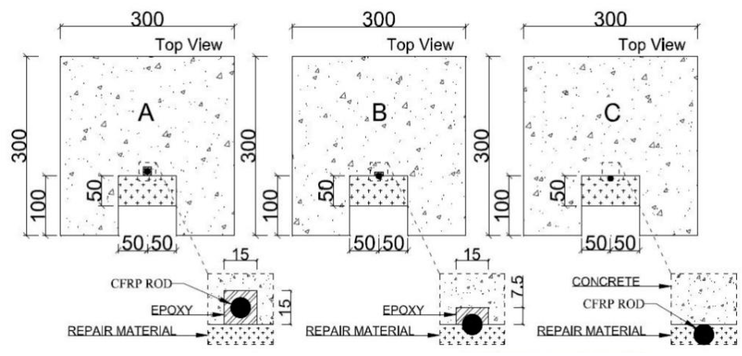
3.1.2. Near-Surface Mounted (NSM) FRP Strengthening
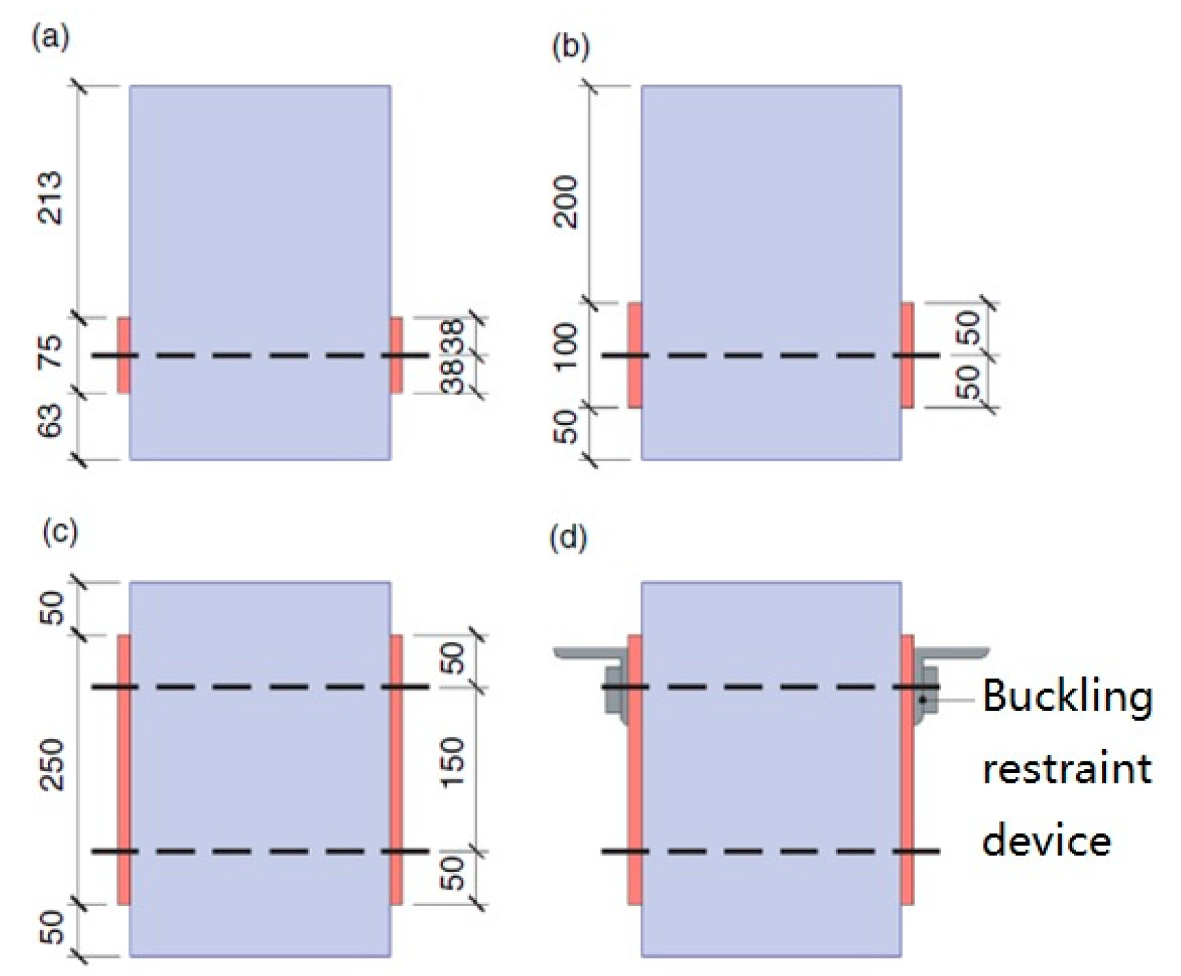
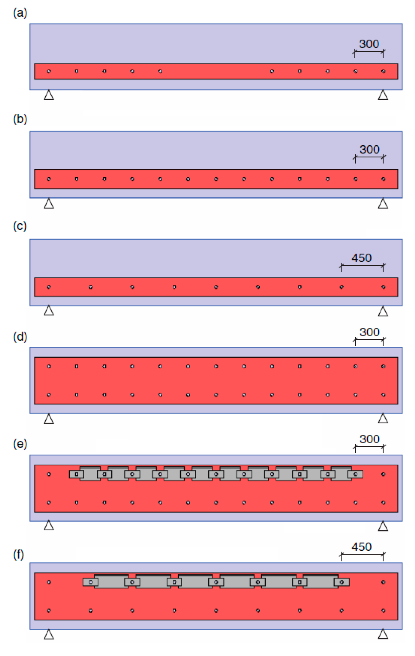
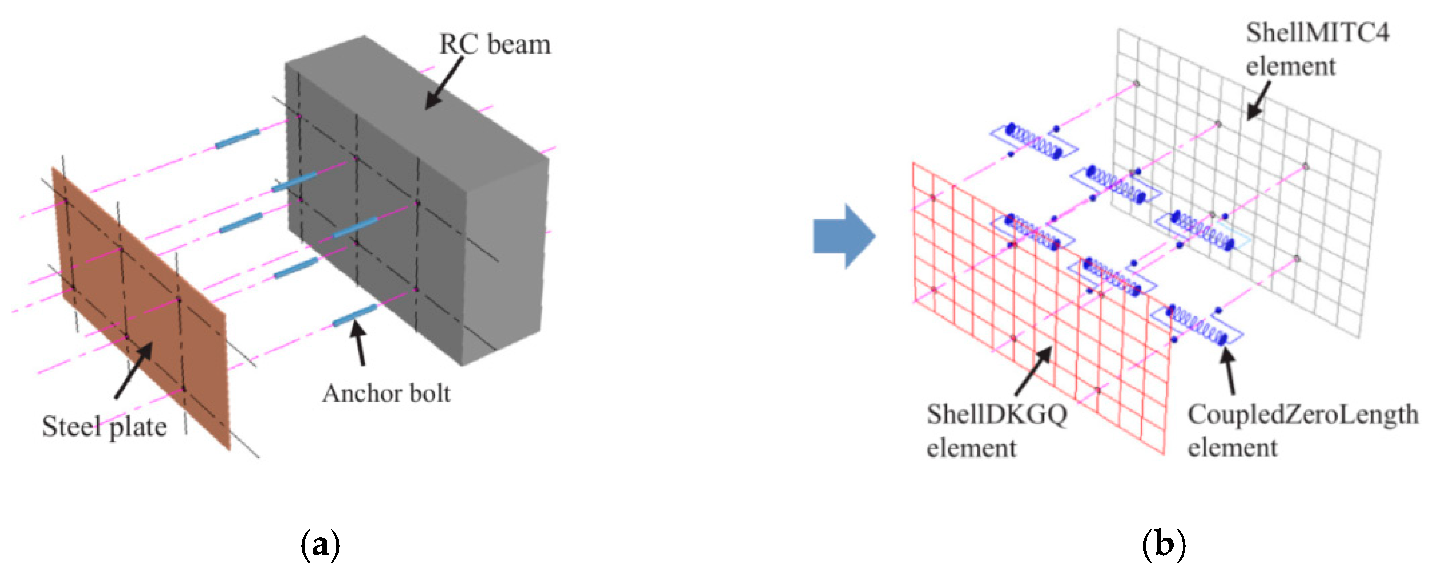
3.1.3. Bolted Side Plating (BSP) Technique
3.2. Repair Method of Post-Fire Slab
3.2.1. Section Enlargement Strengthening
3.2.2. Replacement of Concrete Reinforcement Method
3.2.3. Fiber Reinforced Polymer (FRP) Strengthening
4. Analytical Model of Flexural Members
4.1. Residual Bearing Capacity of Flexural Elements
- Mn is the flexural capacity of the fire-exposed RC beam, kNm;
- As is the area of tension steel, mm2;
- fyT is the residual strength of reinforcing steel, MPa;
- d* is the effective depth of the damaged concrete section, mm;
- b* is the width of the damaged concrete section, mm.
4.2. FRP Strengthening
- fT is the tensile strengths at an elevated temperature T, °C;
- α1 = 0.556, α2 = 5.624, and α3 = 0.630.
- τm is the bond strength, MPa;
- sm is slip at peak bond stress, mm;
- α and α’ are parameters defining the local bonding stress–slip relationship.
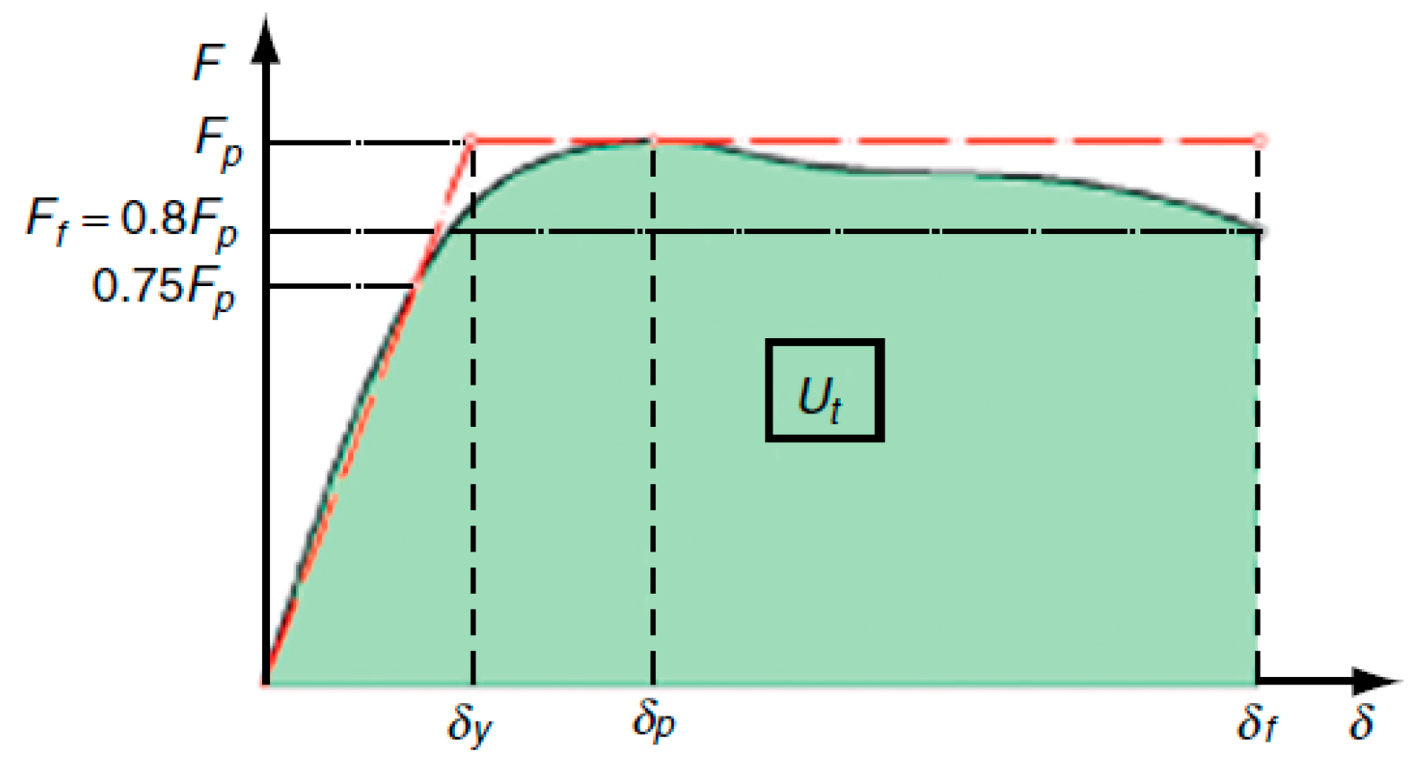
4.3. BSP Technique
- Pst is the tensile force of longitudinal tensile reinforcement, kN;
- Vd is the dowel force of tensile reinforcement, kN;
- Tv is the tensile force of stirrups, kN;
- fct is the tensile strength of concrete material, MPa;
- Ast is the sectional area of longitudinal tensile reinforcements, mm2;
- αE is the ratio between the elastic moduli of rebar and concrete;
- Asv, Sv, and fyv are the cross-sectional area (mm2), spacing (mm), and yield strength of stirrups (MPa);
- x is the depth of the shear-compression zone, mm;
- d0 is the effective depth of RC beam, mm;
- is the beam length, mm;
- Kb is the shear stiffness of an anchor bolt, kN/mm;
- Sb is the horizontal bolt spacing, mm.
- τc is the shear stress of concrete in the shear-compression zone, MPa;
- σc is the compressive stress of concrete in the shear-compression zone, MPa;
- fc is the compressive strength of concrete material, MPa.
5. Conclusions
- (1)
- The externally bonded reinforcement (EBR), near-surface mounted fiber reinforced polymer (NSM FRP) strengthening, and bolted side-plating (BSP) technique were adopted to repair fire-damaged RC beams. Moreover, the section enlargement strengthening, replacement of concrete reinforcement method, and fiber reinforced polymer (FRP) strengthening were applicated to repair slabs after exposure to elevated temperatures. Since section enlargement is an economic and effective method, it is widely used in civil engineering.
- (2)
- The FRP has been widely used for the repairing of post-fire beams and slabs all around the world. The mechanical properties and bonding properties of EBR and NSM FRP systems of bending members represented by beams have been extensively studied, and it has been found that compared with EBR, NSM FRP has more obvious advantages, such as better anchoring ability, better bonding characteristics, and higher ductility. However, when using epoxy resin as an adhesive, it is necessary to ensure fire protection of the repaired members because the epoxy resin is sensitive to fire. The test results conducted by a large number of researchers showed that the fire-damaged RC beams repaired by BSP technology exhibited obvious enhancement in shear capacity, stiffness, and ductility. However, at present, the method of section enlargement is the most economical and applicable method, and the construction is convenient.
- (3)
- One major question is the level of fire resistance of the components after the repair. Whether considering externally-bonded reinforcement, near surface-mounted FRP, bolted side plating, or jacketing with high- and ultra-high-performance concretes or mortars, all are considered a permanent repair. Hence, it is necessary to provide fire protection of the repaired components.
Author Contributions
Funding
Conflicts of Interest
References
- Jiang, C.J.; Lu, Z.D.; Li, L.Z. Shear Performance of Fire-Damaged RC Beams Repaired by a Bolted Side-Plating Technique. J. Struct. Eng. 2017, 143. [Google Scholar] [CrossRef]
- Chen, M.T.; Young, B. Material properties and structural behavior of cold-Formed steel elliptical hollow section stub columns. Thin-Walled Struct. 2019, 134, 111–126. [Google Scholar] [CrossRef]
- Li, L.Z.; Bai, Y.; Yu, K.Q.; Yu, J.T.; Lu, Z.D. Reinforced high-strength engineered cementations composite (ECC) columns under eccentric compression: Experiment and theoretical model. Eng. Struct. 2019, 198, 109541. [Google Scholar] [CrossRef]
- Zhou, J.; Wang, L. Repair of fire-Damaged reinforced concrete members with axial Load: A review. Sustainability 2019, 11, 963. [Google Scholar] [CrossRef]
- Lai, M.; Hanzic, L.; Ho, J.C.M. Fillers to improve passing ability of concrete. Struct. Concr. 2019, 20, 185–197. [Google Scholar] [CrossRef]
- Yaqub, M.; Bailey, C.G. Repair of fire damaged circular RC columns with FRP composites. Constr. Build. Mater. 2011, 25, 359–370. [Google Scholar] [CrossRef]
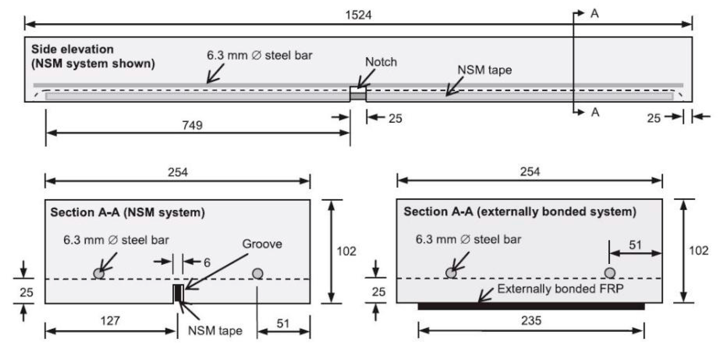
- Burke, P.J.; Bisby, L.A.; Green, M.F. Effects of elevated temperature on near surface mounted and externally bonded FRP strengthening systems for concrete. Cem. Concr. Compos. 2013, 35, 190–199. [Google Scholar] [CrossRef]
- Palmieri, A.; Matthys, S.; Taerwe, L. Experimental investigation on fire endurance of insulated concrete beams strengthened with near surface mounted FRP bar reinforcement. Compos. Part B 2012, 43, 885–895. [Google Scholar] [CrossRef]
- Palmieri, A.; Matthys, S.; Taerwe, L. Fire Endurance and Residual Strength of Insulated Concrete Beams Strengthened with Near-Surface Mounted Reinforcement. J. Compos. Constr. 2013, 17, 454–462. [Google Scholar] [CrossRef]
- Thi, C.N.; Pansuk, W.; Torres, L. Flexural behavior of fire-Damaged RC slabs repaired with near-Surface mounted (NSM) carbon fiber reinforced polymer (CFRP) rods. J. Adv. Concr. Technol. 2015, 13, 15–29. [Google Scholar] [CrossRef]
- Kodur, V.K.R.; Yu, B. Evaluating the Fire Response of Concrete Beams Strengthened with Near-Surface-Mounted FRP Reinforcement. J. Compos. Constr. 2013, 17, 517–529. [Google Scholar] [CrossRef]
- Rein, G.; Abecassis, E.C.; Carvel, R. The Dalmarnock Fire Tests: Experiments and Modeling; School of Engineering and Electronics, University of Edinburgh: Edinburgh, UK, 2007. [Google Scholar]
- Al-Mahmoud, F.; Castel, A.; Francois, R.; Tourneur, C. RC beams strengthened with NSM CFRP rods and modeling of peeling-Off failure. Compos. Struct. 2010, 92, 1920–1930. [Google Scholar] [CrossRef]
- De Lorenzis, L.; Teng, J.G. Near-Surface mounted FRP reinforcement: An emerging technique for strengthening structures. Compos. Part B 2007, 38, 119–143. [Google Scholar] [CrossRef]
- Li, L.Z.; Lo, S.H.; Su, R.K.L. Experimental study of moderately RC beams strengthened with bolted-Side steel plates. Adv. Struct. Eng. 2013, 16, 499–516. [Google Scholar] [CrossRef]
- Kodur Venkatesh, K.R.; Dwaikat, M.M.S.; Dwaikat, M.B. High-Temperature Properties of Concrete for Fire Resistance Modeling of Structures. ACI Mater. J. 2008, 105, 517–527. [Google Scholar]
- Arioz, O. Effects of elevated temperatures on properties of concrete. Fire Saf. J. 2007, 42, 516–522. [Google Scholar] [CrossRef]
- Raut, N.K.; Kodur, V.K.R. Response of High-Strength Concrete Columns under Design Fire Exposure. J. Struct. Eng. 2011, 137, 69–79. [Google Scholar] [CrossRef]
- Tan, K.H.; Yao, Y. Fire Resistance of RC Columns Subjected to 1-, 2-, and 3-Face Heating. J. Struct. Eng. 2004, 130, 1820–1828. [Google Scholar] [CrossRef]
- Wu, B.; Hong, Z.; Tang, G.H.; Wang, C. Fire Resistance of RC Columns with Square Cross Section. Adv. Struct. Eng. 2007, 4, 353–369. [Google Scholar] [CrossRef]
- Han, C.G.; Han, M.C.; Heo, Y.S. Improvement of residual compressive strength and spalling resistance of high-Strength RC columns subjected to fire. Constr. Build. Mater. 2009, 23, 107–116. [Google Scholar] [CrossRef]
- Kodur, V.K.R.; Wang, T.C.; Cheng, F.P. Predicting the fire resistance behavior of high strength concrete columns. Cem. Concr. Compos. 2004, 26, 141–153. [Google Scholar] [CrossRef]
- Ding, F.X.; Li, Z.; Cheng, S.S.; Yu, Z.W. Stress redistribution of simply supported RC beams under fire conditions. J. Cent. South Univ. 2018, 25, 2093–2106. [Google Scholar] [CrossRef]
- Hou, X.; Ren, P.; Rong, Q.; Zheng, W.; Zhan, Y. Effect of fire insulation on fire resistance of hybrid-fiber reinforced reactive powder concrete beams. Compos. Struct. 2019, 209, 219–232. [Google Scholar] [CrossRef]
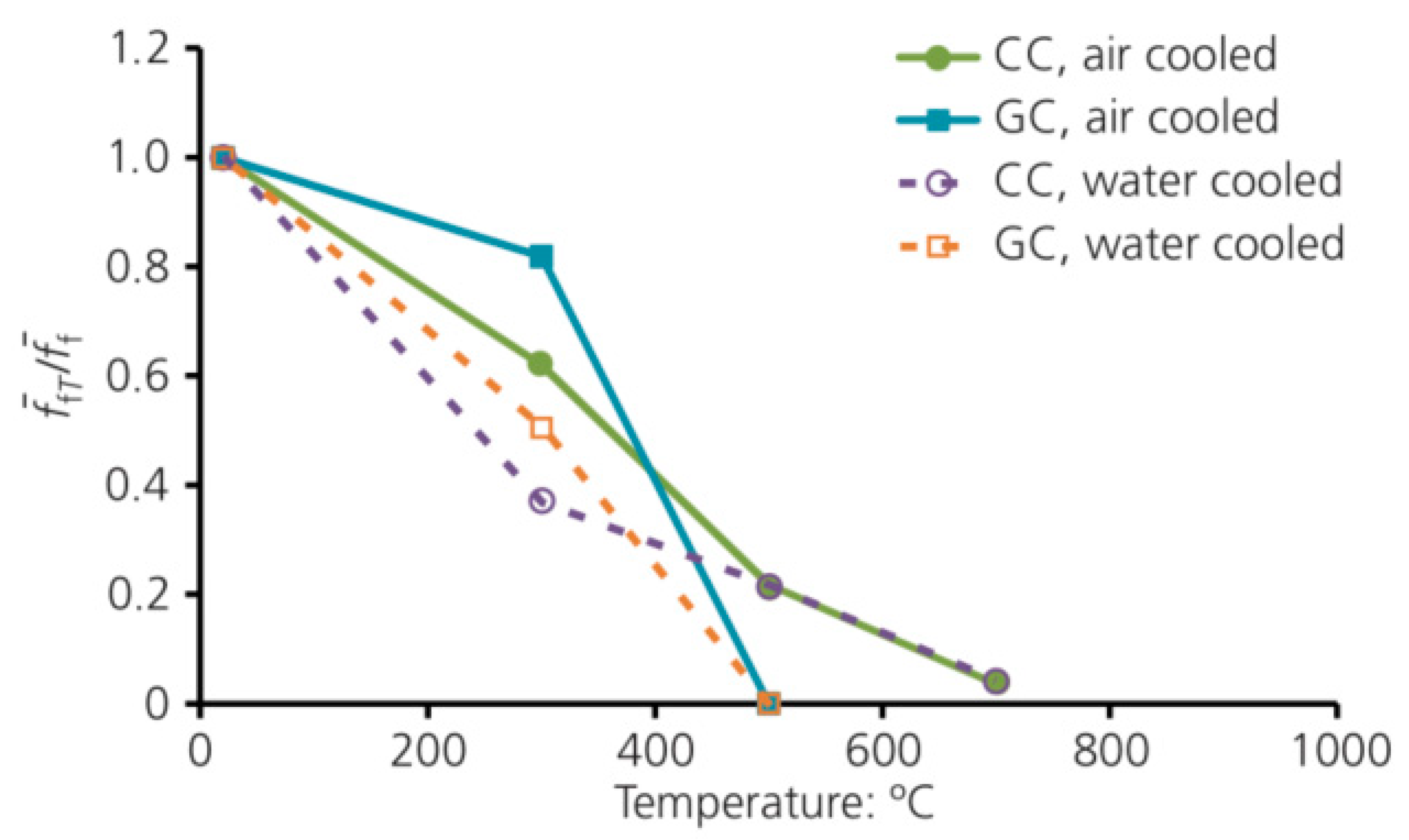
- Santos, C.C.; Rodrigues, J.P.C. Residual mechanical properties of calcareous and granite aggregate concretes after fire. Mag. Concr. Res. 2014, 66, 845–857. [Google Scholar] [CrossRef]
- Li, L.Z.; Liu, X.; Yu, J.T.; Lu, Z.D.; Su, M.N.; Liao, J.H.; Xia, M. Experimental study on seismic performance of post-Fire reinforced concrete frames. Eng. Struct. 2019, 179, 161–173. [Google Scholar] [CrossRef]
- Jiang, C.J.; Yu, J.T.; Li, L.Z.; Wang, X.; Wang, L.; Liao, J.H. Experimental study on the residual shear capacity of fire-damaged RC frame beams and cantilevers. Fire Saf. J. 2018, 100, 140–156. [Google Scholar] [CrossRef]
- Huang, Z. The behaviour of reinforced concrete slabs in fire. Fire Saf. J. 2010, 45, 271–282. [Google Scholar] [CrossRef]
- Wu, Q.; Yang, F.Y.; Sun, G.Q.; Liu, W.Q.; Wang, L. Analytical method for determination of temperature-Induced interfacial shear stress in foam-Core composite sandwich materials. Plast. Rubber Compos. 2018, 47, 232–239. [Google Scholar] [CrossRef]
- Wang, L.; Wu, Z.M.; Liu, W.Q.; Wan, L. Structural behavior of load-bearing sandwich wall panels with GFRP skins and a foam-Web core. Sci. Eng. Compos. Mater. 2016, 25, 173–188. [Google Scholar] [CrossRef]
- Wang, L.; Liu, W.Q.; Fang, Y.; Wan, L.; Huo, R.L. Axial crush behavior and energy absorption capability of foam-filled GFRP tubes manufactured through vacuum assisted resin infusion process. Thin-Walled Struct. 2016, 98, 263–273. [Google Scholar] [CrossRef]
- Xia, Y.W.; Li, X.P.; Peng, Y.; Lai, M.H.; Wang, L. Impact and Post-Impact Performance of Sandwich Wall Boards with GFRP Face Sheets and a Web-Foam Core: The Effects of Impact Location. Materials 2018, 11, 1714. [Google Scholar] [CrossRef] [PubMed]
- Wang, X.K.; Ma, Y.L.; Liu, W.Q.; Liang, R.F.; Wang, L. Mode I interfacial fracture characterization of foam core sandwich materials at elevated temperatures. J. Reinf. Plast. Compos. 2018, 36, 1009–1018. [Google Scholar] [CrossRef]
- Fang, Y.; Wang, K.; Hui, D.; Xu, F.J.; Liu, W.Q.; Yang, S.L.; Wang, L. Monitoring of seawater immersion degradation in glass fibre reinforced polymer composites using quantum dots. Compos. Part B 2017, 112, 93–102. [Google Scholar] [CrossRef]
- Wang, L.; Fan, X.M.; Chen, H.; Liu, W.Q. Axial crush behavior and energy absorption capability of foam-Filled GFRP tubes under elevated and high temperature. Compos. Struct. 2016, 149, 339–350. [Google Scholar] [CrossRef]
- Zhang, L.F.; Liu, W.Q.; Wang, L.; Ling, Z.B. Mechanical behavior and damage monitoring of pultruted wood-Cored GFRP sandwich components. Compos. Struct. 2019, 215, 502–520. [Google Scholar] [CrossRef]
- Lam, L.; Teng, J.G. Design oriented stress strain model for FRP confined concrete. Constr. Build. Mater. 2003, 17, 471–489. [Google Scholar] [CrossRef]
- Lam, L.; Teng, J.G. A new stress strain Model for FRP confined concrete. Proc. FRP Compos. 2001, 1, 283–292. [Google Scholar]
- Ji, G.F.; Li, G.Q.; Alaywan, W. A new fire resistant FRP for externally bonded concrete repair. Constr. Build. Mater. 2013, 42, 87–96. [Google Scholar] [CrossRef]
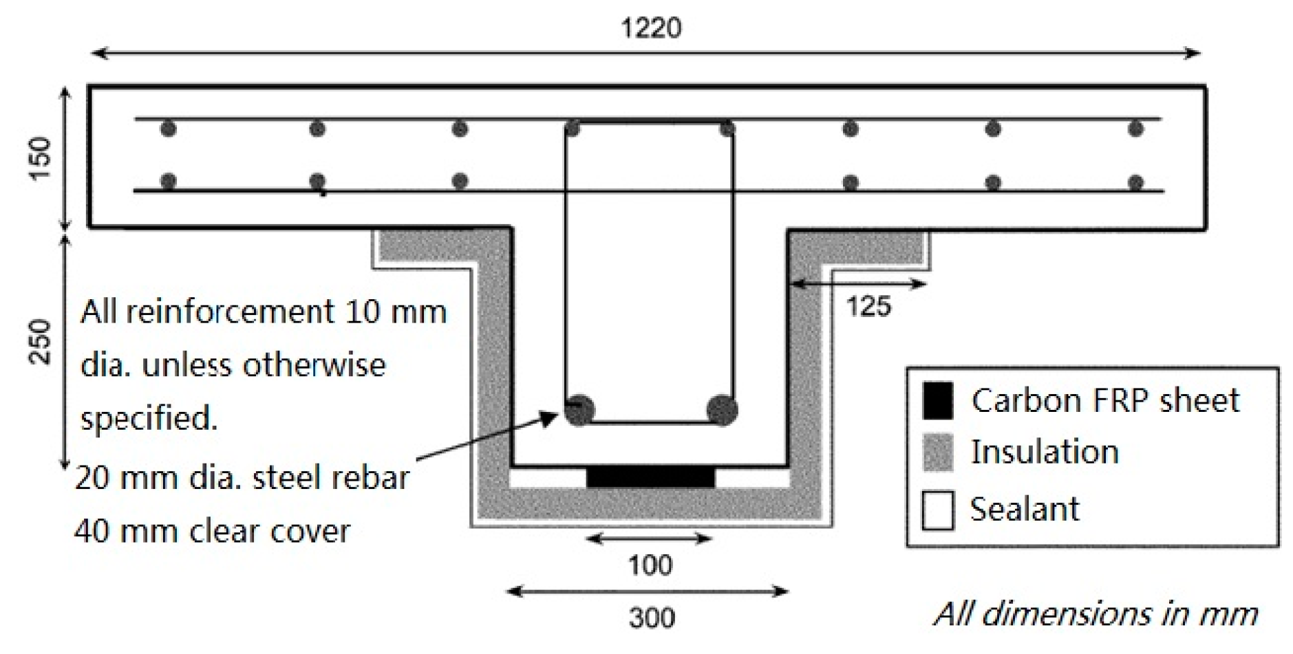
- Williams, B.; Kodur, V.K.R.; Green, M.F.; Bisby, L.A. Fire endurance of fiber-Reinforced polymer strengthened concrete T-beams. ACI Struct. J. 2008, 105, 60–67. [Google Scholar]
- Oehlers, D.J.; Nguyen, N.T.; Ahmed, M.; Bradford, M.A. Transverse and longitudinal partial interaction in composite bolted side-Plated reinforced-Concrete beams. Struct. Eng. Mech. 1997, 5, 553–563. [Google Scholar] [CrossRef]
- Su, R.K.L.; Siu, W.H. Nonlinear response of bolt groups under in-Plane loading. Eng. Struct. 2007, 29, 626–634. [Google Scholar] [CrossRef]
- Siu, W.H.; Su, R.K.L. Load–Deformation prediction for eccentrically loaded bolt groups by a kinematic hardening approach. J. Constr. Steel Res. 2009, 65, 436–442. [Google Scholar] [CrossRef]
- Li, L.Z.; Wu, Z.L.; Yu, J.T.; Wang, X.; Zhang, J.X.; Lu, Z.D. Numerical simulation of the shear capacity of bolted side-Plated RC beams. Eng. Struct. 2018, 171, 373–384. [Google Scholar] [CrossRef]
- Lo, S.H.; Li, L.Z.; Su, R.K.L. Optimization of partial interaction in bolted side-Plated reinforced concrete beams. Comput. Struct. 2014, 131, 70–80. [Google Scholar] [CrossRef]
- Li, L.Z.; Liu, X.; Luo, Y.; Su, M.N.; Zhu, J.H. Flexural performance of bolted-Side-Plated RC beams with buckling restraining. ACI Struct. J. 2019. [Google Scholar] [CrossRef]
- Yao, L. Security Identification and Strengthening Design Studies on a Concrete Frame Structure after Fire (in China). Master’s Thesis, Changsha University of Technological, Changsha, China, 2015. [Google Scholar]
- Thanoon, W.A.; Jaafar, M.S.; Kadir, M.R.A.; Noorzaei, J. Repair and structural performance of initially cracked RC slabs. Constr. Build. Mater. 2005, 19, 595–603. [Google Scholar] [CrossRef]
- Yang, X.G. The Damage Identifying and Repair Reinforcement of the RC After Fire. Master’s Thesis, Tianjin University of Technological, Tianjin, China, 2006. [Google Scholar]
- Maluk, C.; Terrasi, G.P.; Bisby, L.; Stutz, A.; Hugi, E. Fire resistance tests on thin CFRP prestressed concrete slabs. Constr. Build. Mater. 2015, 101, 558–571. [Google Scholar] [CrossRef]
- Haddad, R.H.; Al-Mekhlafy, N.; Ashteyat, A.M. Repair of heat-Damaged RC slabs using fibrous composite materials. Constr. Build. Mater. 2011, 25, 1213–1221. [Google Scholar] [CrossRef]
- Gherdaoui, M.; Guenfoud, M.; Madi, R. Punching behavior of strengthened and repaired RC slabs with CFRP. Constr. Build. Mater. 2018, 170, 272–278. [Google Scholar] [CrossRef]
- Harajli, M.H.; Soudki, K.A. Shear Strengthening of Interior Slab–Column Connections Using Carbon Fiber-Reinforced Polymer Sheets. J. Compos. Constr. 2003, 7, 145–153. [Google Scholar] [CrossRef]
- Kodur, V.K.R.; Dwaikat, M.B.; Fike, R.S. An approach for evaluating the residual strength of fire-exposed RC beams. Mag. Concr. Res. 2010, 62, 479–488. [Google Scholar] [CrossRef]
- Dai, J.G.; Gao, W.Y.; Teng, J.G. Finite element modeling of insulated FRP-Strengthened RC beams exposed to fire. J. Compos. Constr. 2014, 19, 428–432. [Google Scholar]
- Firmo, J.P.; Arruda, M.R.T.; Correia, J.R. Numerical simulation of the fire behaviour of thermally insulated RC beams strengthened with EBR-CFRP strips. Compos. Struct. 2015, 126, 360–370. [Google Scholar] [CrossRef]
- Firmo, J.P.; Arruda, M.R.T.; Correia, J.R.; Rosa, I.C. Three-Dimensional finite element modelling of the fire behaviour of insulated RC beams strengthened with EBR and NSM CFRP strips. Compos. Struct. 2017, 183, 124–136. [Google Scholar] [CrossRef]
- Arruda, M.R.T.; Firmo, J.P.; Correia, J.R.; Tiago, C. Numerical modelling of the bond between concrete and CFRP laminates at elevated temperatures. Eng. Struct. 2016, 110, 233–243. [Google Scholar] [CrossRef]
- Hawileh, R.A.; Naser, M.; Zaidan, W.; Rasheed, H.A. Modeling of insulated CFRP-Strengthened RC T-Beam exposed to fire. Eng. Struct. 2009, 31, 3072–3079. [Google Scholar] [CrossRef]
- Ahmed, A.; Kodur, V.K.R. Effect of bond degradation on fire resist of FRP-Strengthened RC beams. Compos. Part B 2011, 42, 226–237. [Google Scholar] [CrossRef]
- Yu, B.; Kodur, V.K.R. Effect of high temperature on bond strength of near-surface mounted FRP reinforcement. Compos. Struct. 2014, 110, 88–97. [Google Scholar] [CrossRef]
- Galati, N.; Nanni, A.; Dharani, L.R.; Aiello, M.A. Thermal effects on bond between FRP rebars and concrete. Compos. Part A 2006, 37, 1223–1230. [Google Scholar] [CrossRef]
- Dai, J.G.; Gao, W.Y.; Teng, J.G. Bond-Slip model for FRP laminates externally bonded to concrete at elevated temperature. J. Compos. Constr. 2014, 17, 217–228. [Google Scholar] [CrossRef]
- Bisby, L.A.; Kodur, V.R.; Green, M.F. Fire Endurance of Fiber-Reinforced Polymer-Confined Concrete Columns. ACI Struct. J. 2005, 102, 883–891. [Google Scholar]
- Blontrock, H.; Taerwe, L.; Vandevelde, P. Fire tests on concrete beams strengthened with fibre composite laminates. In Proceedings of the International PhD Symposium in Civil Engineering, Vienna, Austria, 5–7 October 2000; Volume 2, pp. 151–161. [Google Scholar]
- de Sena Cruz, J.M.; Oliveira de Barros, J.A. Bond between near-surface mounted carbon-Fiber-Reinforced polymer laminate strips and concrete. J. Compos. Construct. 2004, 8, 519–527. [Google Scholar] [CrossRef]
- Yu, J.T.; Liu, K.K.; Li, L.Z.; Wang, Y.C.; Yu, K.Q.; Xu, Q.F. A simplified method to predict the fire resistance of RC Beams strengthened with near-Surface mounted CFRP. Compos Constr. 2018, 193, 1–7. [Google Scholar] [CrossRef]
- Li, L.Z.; Cai, Z.W.; Lu, Z.D.; Zhang, X.L.; Wang, L. Shear performance of bolted side-Plated RC beams. Eng. Struct. 2017, 144, 73–87. [Google Scholar] [CrossRef]
- Tsuboi, Y.; Tanaka, H.; Suenaga, Y. A Study on Failure of RC Members under combined stresses (Part 4): Especially on Beam under Bending Moment and Shearing Force. Trans. Archit. Inst. Jpn. 1961, 67, 1–9. [Google Scholar] [CrossRef]


| Beam | FRP | Adhesive | Tg °C | Insulation | Thick Bottom (mm) | Thick Side (mm) | Density (kg/m3) | Conductivity (W/mK) |
|---|---|---|---|---|---|---|---|---|
| B1-F3-1 | GFRP | Epoxy Sikadur 30 | 62 | Promat L-500 | 50 + 50 | 20 | 500 | 0.09 |
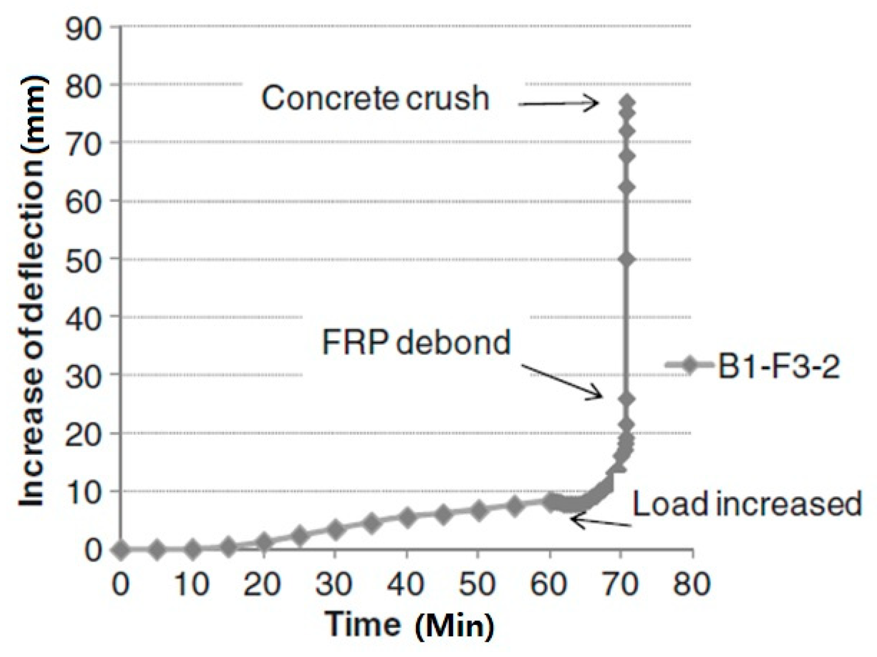
| B1-F3-2 | GFRP | Epoxy Sikadur 30 | 62 | HPC + Omega | 25 + 20 | 10 + 10 | 527 | 0.07 |
| B1-F3-3 | GFRP | Epoxy Sikadur 30 | 62 | HPC + Omega | 35 + 20 | 10 + 10 | 527 | 0.07 |
| B1-F3-4 | GFRP | Epoxy Sikadur 30 | 65 | HPC + Omega | 20 + 15 | 10 + 10 | 527 | 0.07 |
| B2-F3-1 | CFRP | Epoxy Fortresin | 65 | Promat L - 500 | 30 + 30 | 20 | 500 | 0.09 |
| B4-F3-1 | CFRP | Mortar Sikagrout 212 | 65 | HPC + Omega | 10 + 10 | 10 + 10 | 527 | 0.07 |
| Specimen | Plate Thickness (mm) | Plate Depth (mm) | Bolt Spacing (mm) | Number of Rows of Bolts | Shear Capacity | Stiffness | Ductility | |||
|---|---|---|---|---|---|---|---|---|---|---|
| Pu (kN) | Change (%) | Ke (kN mm) | Change (%) | Ut (kN mm) | Change (%) | |||||
| CTRL | — | — | — | — | 690 | 19% | 88.5 | 11% | 3796 | 47% |
| CTRL-AF | — | — | — | — | 580 | — | 79.4 | — | 2580 | — |
| P2B2-AF | 4 | 200 | 200 | 2 | 800 | 38% | 90.2 | 14% | 5812 | 125% |
| P2B1-AF | 4 | 200 | 100 | 3 | 930 | 60% | 88.6 | 12% | 18,927 | 634% |
| P3B2-AF | 4 | 300 | 200 | 2 | 840 | 45% | 82.1 | 3% | 15,359 | 495% |
| P3B1-AF | 4 | 300 | 100 | 3 | 1030 | 78% | 113.5 | 43% | 20,458 | 693 |
© 2019 by the authors. Licensee MDPI, Basel, Switzerland. This article is an open access article distributed under the terms and conditions of the Creative Commons Attribution (CC BY) license (http://creativecommons.org/licenses/by/4.0/).
Share and Cite
Ma, W.; Yin, C.; Zhou, J.; Wang, L. Repair of Fire-Damaged Reinforced Concrete Flexural Members: A Review. Sustainability 2019, 11, 5199. https://doi.org/10.3390/su11195199
Ma W, Yin C, Zhou J, Wang L. Repair of Fire-Damaged Reinforced Concrete Flexural Members: A Review. Sustainability. 2019; 11(19):5199. https://doi.org/10.3390/su11195199
Chicago/Turabian StyleMa, Wenxian, Chunxiang Yin, Jun Zhou, and Lu Wang. 2019. "Repair of Fire-Damaged Reinforced Concrete Flexural Members: A Review" Sustainability 11, no. 19: 5199. https://doi.org/10.3390/su11195199
APA StyleMa, W., Yin, C., Zhou, J., & Wang, L. (2019). Repair of Fire-Damaged Reinforced Concrete Flexural Members: A Review. Sustainability, 11(19), 5199. https://doi.org/10.3390/su11195199