Sustainability Improvement in the Design of Lightweight Roofs: A New Prototype of Hybrid Steel and Wood Purlins


Abstract
:1. Introduction
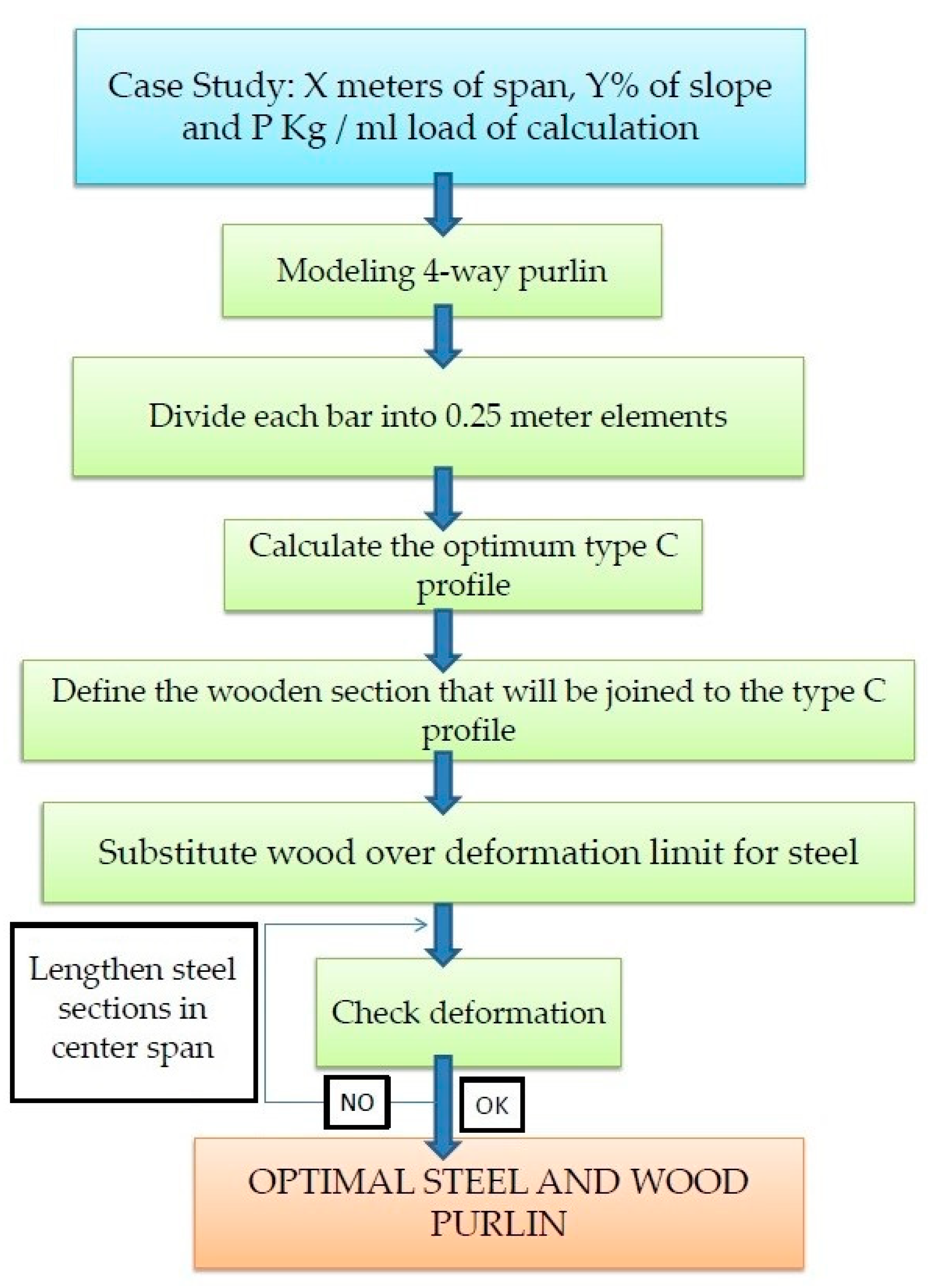
2. Materials and Methods
3. Results and Discussion
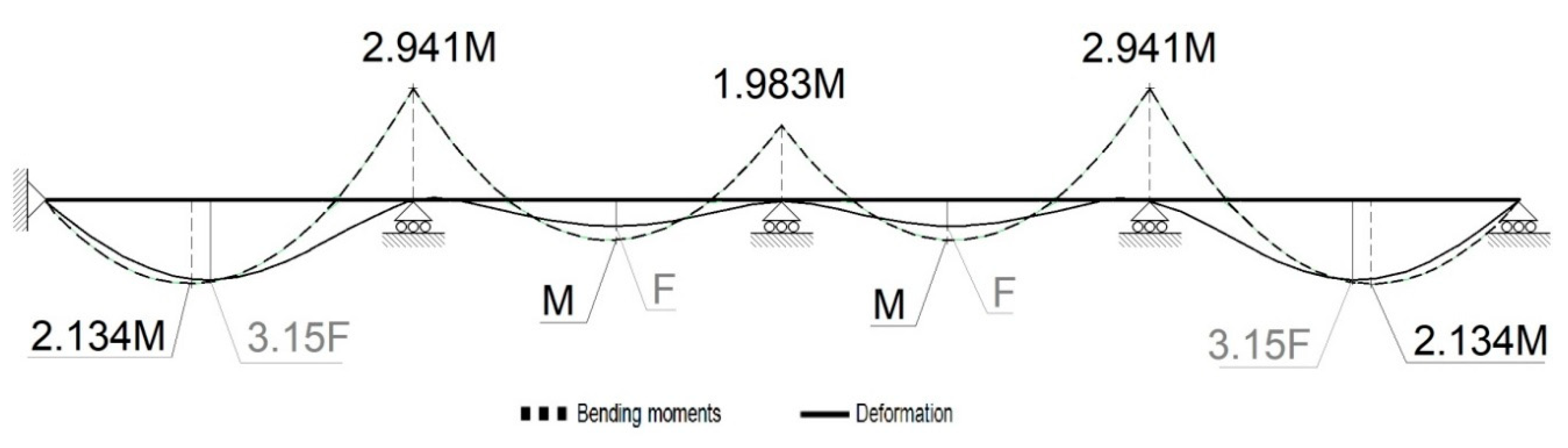
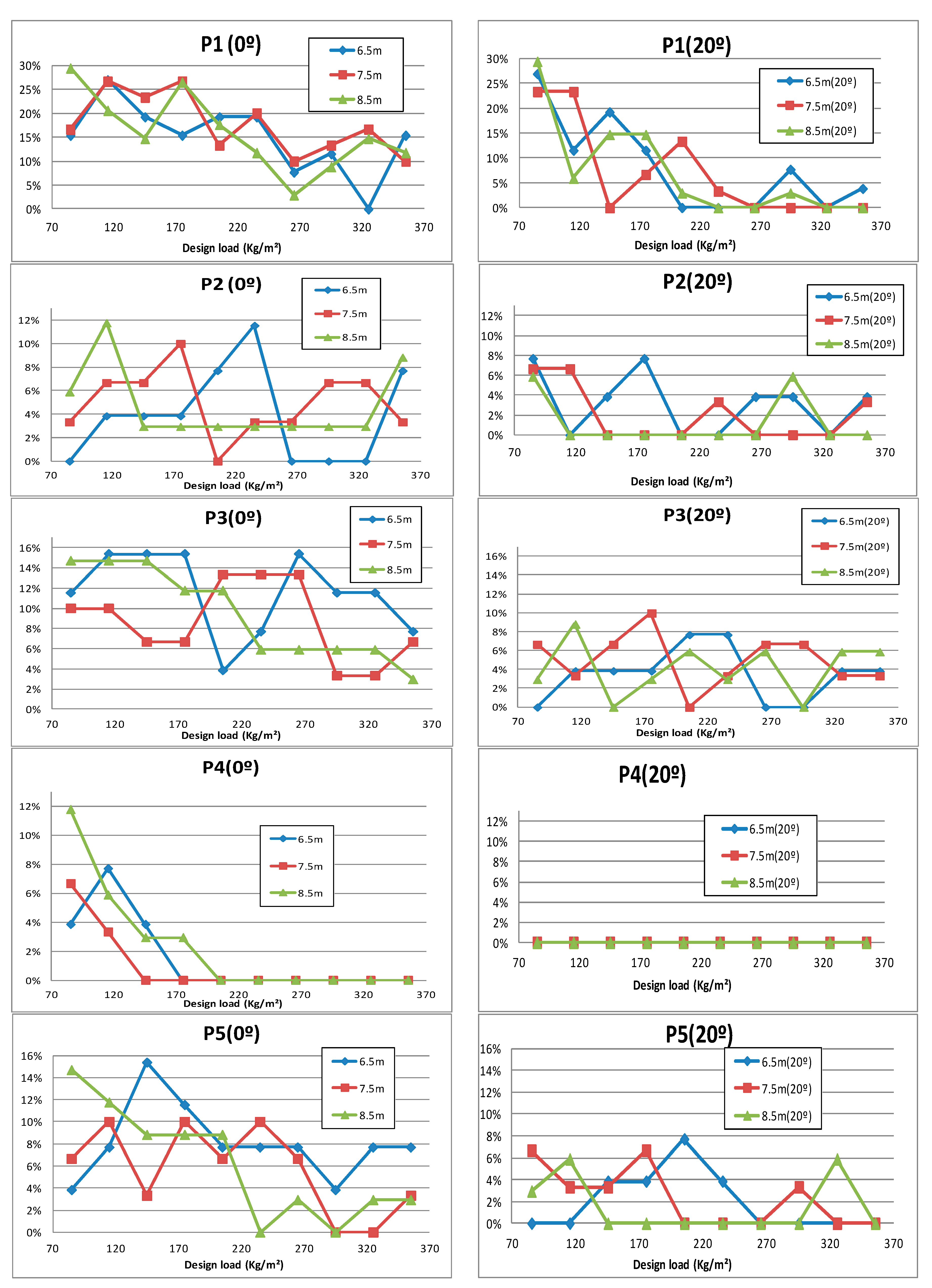
- P1 is the steel portion in the middle of the extreme span (section size A)
- P2 is the steel portion in the second of the supports (section size A)
- P3 is the wooden portion located in the second span (the last of the A-size portions)
- P4 is the steel portion in the middle of the second span (section size B)
- P4 is the steel portion in the middle of the interior spans (section size B)
- P5 is the steel portion in the inner supports (section size B)
3.1. Behavior of Parameters as a Function of Span Length and Loading
- P1: as the loading increases its values decrease (smaller steel sections), complying with the design criteria for tensile stress.
- P1: as the span length increases, its values increase (longer steel sections), complying with the design criteria for deformation. However, those parameters are not so clear for the 8.5-m spans with high loads, because in those cases the design section A is defined by the tensile stress in the second support.
- P1: in comparison with the other parameters, P1 has higher values, which reflects the importance of the deformation in the design of the first span of the purlins.
- P2: has very small values, but a slightly decreasing tendency is appreciated, complying with the design criterion for tensile stress.
- P2 and P3: an antagonistic behavior is observed, which indicates that the length of section A in the second span is always similar; the changes affect the portions of steel and wood.
- P4: in most cases, section B is defined by the design criteria of the intermediate supports (previous point), so that where the tensile stress is much lower, as in the sections corresponding to P4, wooden sections will be inserted. Only under very small loads on very long span lengths will the design criterion of deformation predominate, in which case the section corresponding to P4 will be made of steel.
- P5: the design criterion is clearly and exclusively one of tensile stress and as the loading values and the span lengths increase, the tensile stress values decrease.
3.2. Behavior of the Parameters as a Function of the Slope and the Load
- P1: the design criterion of deformation is of less importance for sloped roofs. Much smaller steel sections will be needed than in flat roofs.
- P2: similar and very small values for flat and sloped roofs.
- P3: somewhat higher values for flat roofs.
- P4: the deformation criterion discussed in the previous point is no longer present and the sloped roofs always have zero values in the range under study.
- P5: somewhat lower values for sloped roofs.
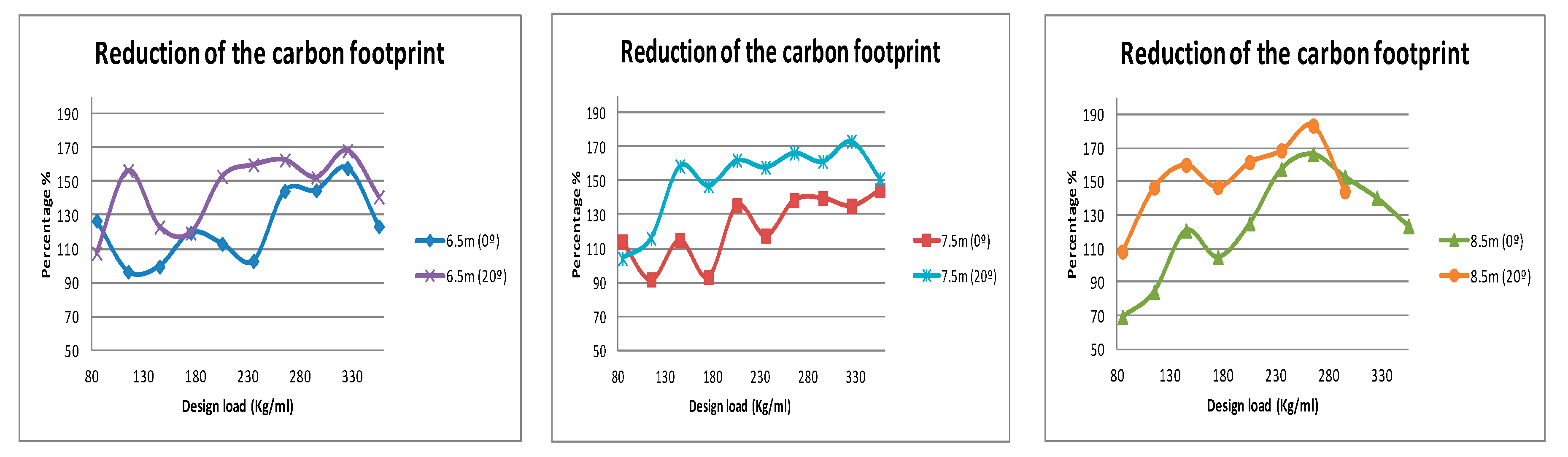
3.3. Sustainability Analysis and Comparison of the SWP and the Steel Purlins
- In the entire range of cases analyzed in this study, there is a very large reduction of the carbon footprint of the SWPs in comparison with the steel purlins.
- The carbon footprint reduction of the SWP purlins in relation to the steel purlins increases as the slope increases, but tends to even out as the design load increases.
- The reduction of the carbon footprint in terms of applied loads shows a rising curve for all span lengths, but the longer the span length, the faster the rise.
- For the smallest loads (the start of the curves), the longer the span length, the greater the reduction in the carbon footprint.
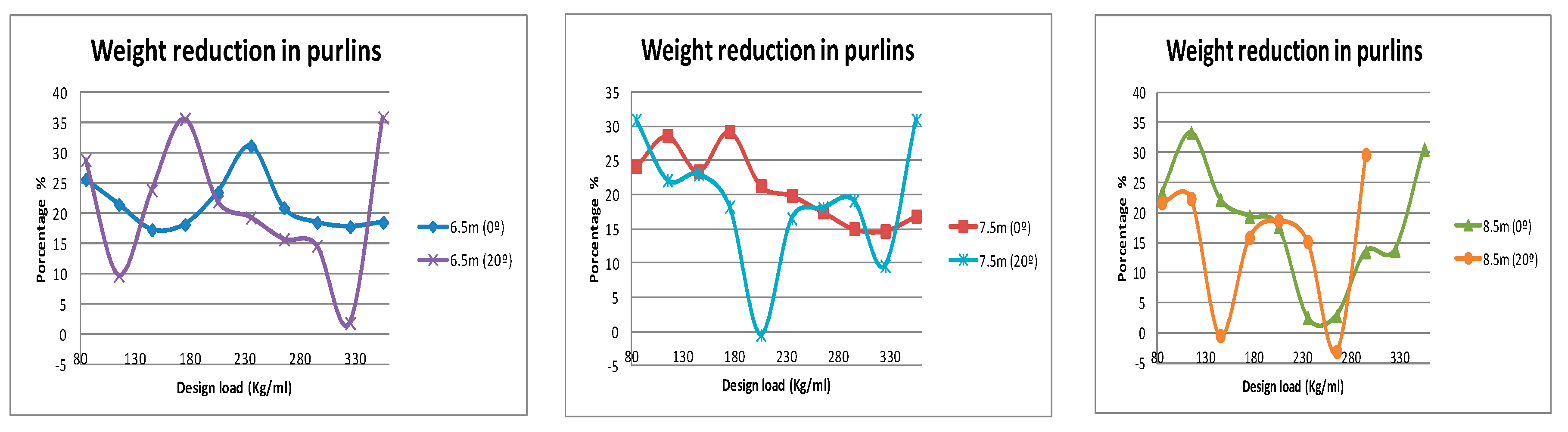
3.4. Analysis and Comparison of the Weight between SWP-Type Purlins and Steel Purlins
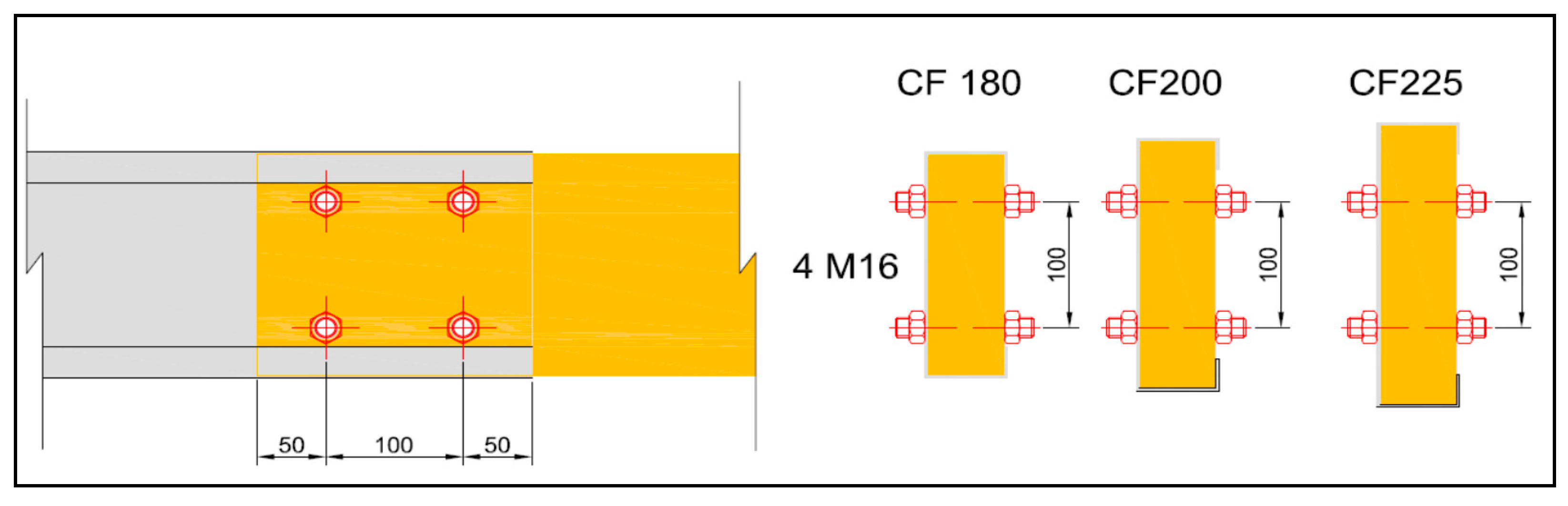
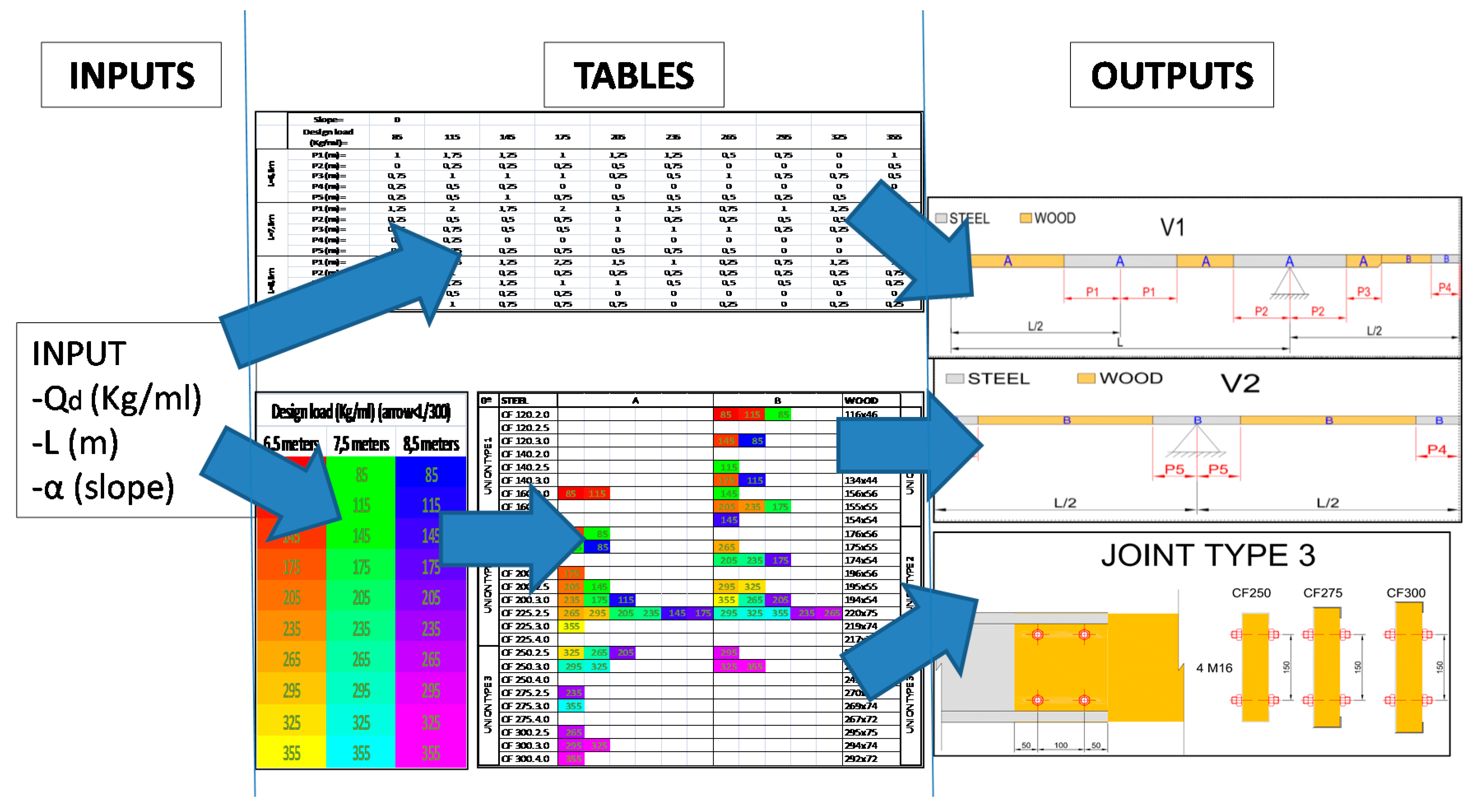
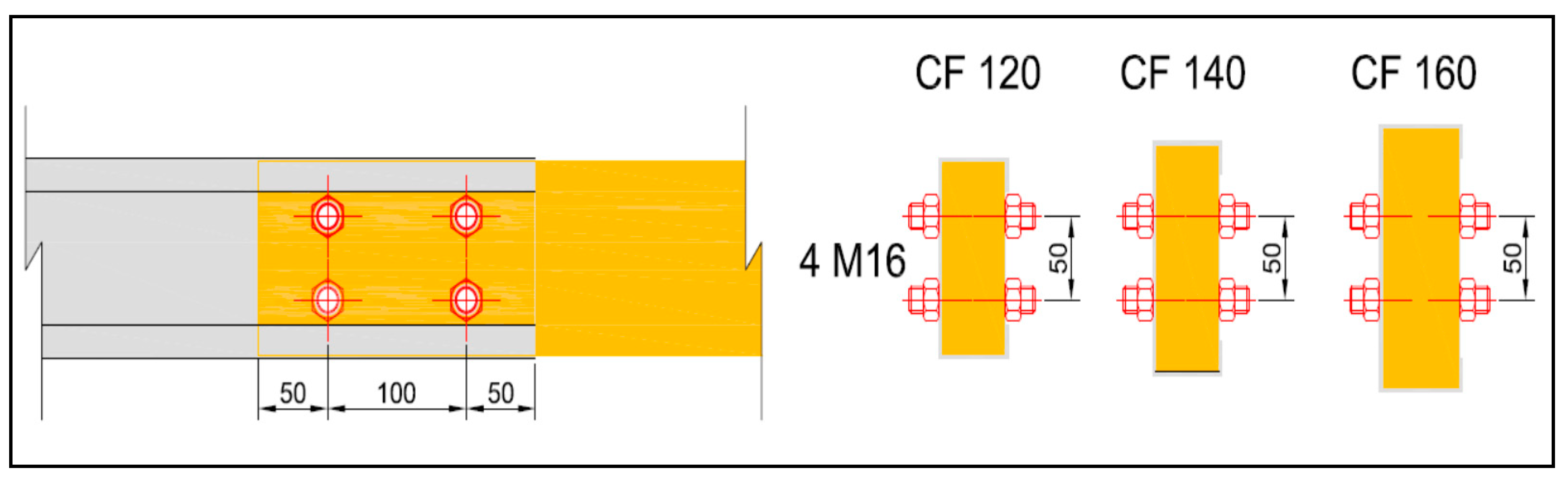
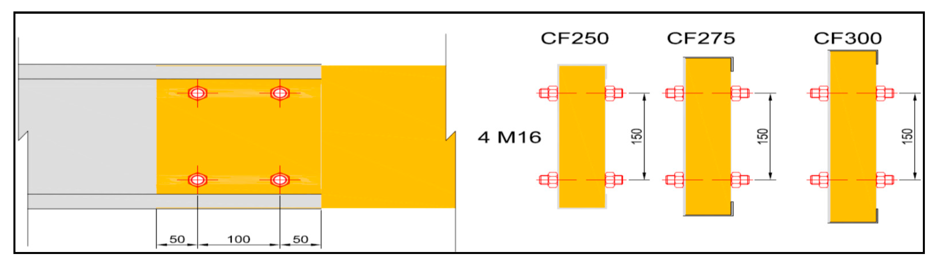
3.5. Design and Selection of the Joint Typology
3.6. Purlin Dimensioning Specifications
4. Conclusions
- Lighter purlins than the type C cold rolled steel purlins are obtained with this new structural typology, which also implies reductions in the material needed for the main structure.
- In the first spans with this type of purlin (continuous over several spans), the predominant design criterion is usually deformation. Given that the elastic modulus of steel is almost 12 times greater than that of wood, in order to obtain good results with regard to this criterion, it is necessary to reinforce the sections of the span centers with sections of cold-formed type C steel.
- When the design criteria is the tensile strength of the material (normally all spans and supports except the first), two situations can occur: in the first, if the design tensile stress values are low and small steel profiles or wooden sections are needed, the result is cold-formed steel sections, because of the small differences between the relative inertia of the two materials and the much higher strength of the steel.
- In the second spans, as the design tensile stress values increase and large wooden or steel profiles are needed, the results become sections of laminated wood, due to the inertias of the rectangular sections that increase much more than those of the type C sections, compensating the shortcomings in terms of material strength.
- A design guide for this new typology of steel + wood purlins has been presented using the technical specifications, with which the purlins can be easily and rapidly dimensioned.
Author Contributions
Funding
Conflicts of Interest
References
- Gan, V.J.; Chan, C.M.; Tse, K.; Lo, I.M.; Cheng, J.C. A comparative analysis of embodied carbon in high-rise buildings regarding different design parameters. J. Clean. Prod. 2017, 161, 663–675. [Google Scholar] [CrossRef]
- Liu, B.; Wang, D.; Xu, Y.; Liu, C.; Luther, M. A multi-regional input–output analysis of energy embodied in international trade of construction goods and services. J. Clean. Prod. 2018, 201, 439–451. [Google Scholar] [CrossRef]
- Upton, B.; Miner, R.; Spinney, M.; Heath, L.S. The greenhouse gas and energy impacts of using wood instead of alternatives in residential construction in the United States. Biomass Bioenergy 2008, 32, 1–10. [Google Scholar] [CrossRef]
- Cuadrado, J.; Zubizarreta, M.; Pelaz, B.; Marcos, I. Methodology to assess the environmental sustainability of timber structures. Constr. Build. Mater. 2015, 86, 149–158. [Google Scholar] [CrossRef]
- Wang, L.; Toppinen, A.; Juslin, H. Use of wood in green building: A study of expert perspectives from the UK. J. Clean. Prod. 2014, 65, 350–361. [Google Scholar] [CrossRef]
- Fino, R.; Tadeu, A.; Simões, N. Influence of a period of wet weather on the heat transfer across a wall covered with uncoated medium density expanded cork. Energy Build. 2018, 165, 118–131. [Google Scholar] [CrossRef]
- Fino, R.; Simões, N.; Tadeu, A. Numerical and experimental evaluation of the drying behaviour of medium density expanded cork boards used as an external coating. Int. J. Sustain. Dev. Plan. 2017, 12, 315–325. [Google Scholar] [CrossRef]
- Tadeu, A.; Moreira, A.; António, J.; Simões, N.; Simões, I. Thermal delay provided by floors containing layers that incorporate expanded cork granule waste. Energy Build. 2014, 68, 611–619. [Google Scholar] [CrossRef] [Green Version]
- De la Fuente, A.; Armengou, J.; Pons, O.; Aguado, A. Multi-criteria decision-making model for assessing the sustainability index of wind-turbine support systems: Application to a new precast concrete alternative. J. Civ. Eng. Manag. 2017, 23, 194–203. [Google Scholar] [CrossRef]
- Pons, O.; de la Fuente, A.; Armengou, J.; Aguado, A. Towards the sustainability in the design of wind towers. Energy Procedia 2017, 115, 41–49. [Google Scholar] [CrossRef]
- Haapio, A.; Viitaniemi, P. A critical review of building environmental assessment tools. Environ. Impact Assess. Rev. 2008, 28, 469–482. [Google Scholar] [CrossRef] [Green Version]
- Aguado, A.; Caño Ad de la Cruz MPilar Gomez, D.; Josa, A. Sustainability assessment of concrete structures within the Spanish structural concrete code. J. Constr. Eng. Manag. 2011, 138, 268–276. [Google Scholar] [CrossRef]
- Pons, O.; de la Fuente, A.; Aguado, A. The use of MIVES as a sustainability assessment MCDM method for architecture and civil engineering applications. Sustainability 2016, 8, 460. [Google Scholar] [CrossRef]
- de la Fuente, A.; Pons, O.; Josa, A.; Aguado, A. Multi-Criteria Decision Making in the sustainability assessment of sewerage pipe systems. J. Clean. Prod. 2016, 112, 4762–4770. [Google Scholar] [CrossRef] [Green Version]
- Caruso, M.C.; Menna, C.; Asprone, D.; Prota, A.; Manfredi, G. Methodology for Life-Cycle Sustainability Assessment of Building Structures. ACI Struct. J. 2017, 114, 323. [Google Scholar] [CrossRef]
- Padilla-Rivera, A.; Amor, B.; Blanchet, P. Evaluating the Link between Low Carbon Reductions Strategies and Its Performance in the Context of Climate Change: A Carbon Footprint of a Wood-Frame Residential Building in Quebec, Canada. Sustainability 2018, 10, 2715. [Google Scholar] [CrossRef]
- Švajlenka, J.; Kozlovská, M. Perception of User Criteria in the Context of Sustainability of Modern Methods of Construction Based on Wood. Sustainability 2018, 10, 116. [Google Scholar] [CrossRef]
- Li, S.; Wu, H.; Ding, Z. Identifying Sustainable Wood Sources for the Construction Industry: A Case Study. Sustainability 2018, 10, 139. [Google Scholar] [CrossRef]
- Hafner, A. How building with wood can be linked to sales of building plots: Results from an exemplary site development in Munich, Germany. Sustainability 2017, 9, 947. [Google Scholar] [CrossRef]
- Zhang, X.; Shahnewaz, M.; Tannert, T. Seismic reliability analysis of a timber steel hybrid system. Eng. Struct. 2018, 167, 629–638. [Google Scholar] [CrossRef]
- Marsono, A.K.B.; Balasbaneh, A.T. Combinations of building construction material for residential building for the global warming mitigation for Malaysia. Constr. Build. Mater. 2015, 85, 100–108. [Google Scholar] [CrossRef]
- Balasbaneh, A.T.; Marsono, A.K.B. Strategies for reducing greenhouse gas emissions from residential sector by proposing new building structures in hot and humid climatic conditions. Build. Environ. 2017, 124, 357–368. [Google Scholar] [CrossRef]
- Balasbaneh, A.T.; Marsono, A.K.B.; Khaleghi, S.J. Sustainability choice of different hybrid timber structure for low medium cost single-story residential building: Environmental, economic and social assessment. J. Build. Eng. 2018, 20, 235–247. [Google Scholar] [CrossRef]
- Stocchero, A.; Seadon, J.K.; Falshaw, R.; Edwards, M. Urban Equilibrium for sustainable cities and the contribution of timber buildings to balance urban carbon emissions: A New Zealand case study. J. Clean. Prod. 2017, 143, 1001–1010. [Google Scholar] [CrossRef]
- Woodard, A.; Milner, H. Sustainability of timber and wood in construction. In Sustainability of Construction Materials, 2nd ed.; Elsevier: Amsterdam, The Netherlands, 2016; pp. 129–157. [Google Scholar]
- Buchanan, A.; John, S.; Love, S. Life cycle assessment and carbon footprint of multistorey timber buildings compared with steel and concrete buildings. N. Z. J. For. 2013, 57, 9–18. [Google Scholar]
- Perez-Garcia, J.; Lippke, B.; Briggs, D.; Wilson, J.B.; Bowyer, J.; Meil, J. The environmental performance of renewable building materials in the context of residential construction. Wood Fiber Sci. 2007, 37, 3–17. [Google Scholar]
- Kaziolas, D.; Zygomalas, I.; Stavroulakis, G.; Baniotopoulos, C. LCA of timber and steel buildings with fuzzy variables uncertainty quantification. Eur. J. Environ. Civ. Eng. 2017, 21, 1128–1150. [Google Scholar] [CrossRef]
- Jakes, J.E.; Arzola, X.; Bergman, R.; Ciesielski, P.; Hunt, C.G.; Rahbar, N.; Tshabalala, M.; Wiedenhoeft, A.C.; Zelinka, S.L. Not just lumber—Using wood in the sustainable future of materials, chemicals, and fuels. JOM 2016, 68, 2395–2404. [Google Scholar] [CrossRef]
- Ward, R. Tackle Climate Change, Use Wood; BC Forestry Climate Change Working Group: Victoria, BC, Canada, 2009.
- García, H.; Biezma, M.; Cuadrado, J.; Zubizarreta, M. Dual-steel portal frame design to withstand a fire exposure of 45 minutes. Int. J. Steel Struct. 2016, 16, 705–717. [Google Scholar] [CrossRef]
- García, H.; Biezma, M.; Cuadrado, J.; Maturana, A. Fire-resistance industrial portal frames: Design with different mechanical properties steels and 35 meters spans. Mater. Struct. 2016, 49, 341–352. [Google Scholar] [CrossRef]
- Canto-Perello, J.; Martinez-Garcia, M.P.; Curiel-Esparza, J.; Martin-Utrillas, M. Implementing sustainability criteria for selecting a roof assembly typology in medium span buildings. Sustainability 2015, 7, 6854–6871. [Google Scholar] [CrossRef]
- Hein, C.; Lawrence, A.; Snelson, T.; Campbell, A.; Heesbeen, C. Hybrid Timber Construction–Combining Material Properties for Energy Efficiency and Sustainability; IABSE Symposium Report; International Association for Bridge and Structural Engineering: Zurich, Switzerland, 2015. [Google Scholar]
- UNE E. 1363: 2000. Fire Resistance Tests; AENOR: Madrid, Spain, 2000.
- Hopkin, D. Predicting the thermal response of timber structures in natural fires using computational ‘heat of hydration’ principles. Fire Mater. 2013, 37, 311–327. [Google Scholar] [CrossRef]
- Laranjeira, J.P.d.S.; Cruz, H.; Pinto, A.P.F.; Pina dos Santos, C.; Pereira, J.F. Reaction to fire of existing timber elements protected with fire retardant treatments: Experimental assessment. Int. J. Arch. Herit. 2015, 9, 866–882. [Google Scholar] [CrossRef]
- ACCESS-STEEL A. SS053-Proyecto Básico: Diseño de Estructura de Correas; ASCEM: Madrid, Spain, 2012.
- García, A. End-of-Degree Project: Análisis de Ciclo de Vida Comparativo Entre un Sistema Constructivo de Madera y un Sistema de Hormigón; 2012. [Google Scholar]
- MPA the Concrete Centre. Whole-life Carbon and Buildings; MPA the Concrete Centre: London, UK, 2016. [Google Scholar]


| Slope = | 0 | ||||||||||
|---|---|---|---|---|---|---|---|---|---|---|---|
| Design Load (Kg/mL)= | 85 | 115 | 145 | 175 | 205 | 235 | 265 | 295 | 325 | 355 | |
| 6.5 m | P1 (m)= | 1 | 1.75 | 1.25 | 1 | 1.25 | 1.25 | 0.5 | 0.75 | 0 | 1 |
| P2 (m)= | 0 | 0.25 | 0.25 | 0.25 | 0.5 | 0.75 | 0 | 0 | 0 | 0.5 | |
| P3 (m)= | 0.75 | 1 | 1 | 1 | 0.25 | 0.5 | 1 | 0.75 | 0.75 | 0.5 | |
| P4 (m)= | 0.25 | 0.5 | 0.25 | 0 | 0 | 0 | 0 | 0 | 0 | 0 | |
| P5 (m)= | 0.25 | 0.5 | 1 | 0.75 | 0.5 | 0.5 | 0.5 | 0.25 | 0.5 | 0.5 | |
| 7.5 m | P1 (m)= | 1.25 | 2 | 1.75 | 2 | 1 | 1.5 | 0.75 | 1 | 1.25 | 0.75 |
| P2 (m)= | 0.25 | 0.5 | 0.5 | 0.75 | 0 | 0.25 | 0.25 | 0.5 | 0.5 | 0.25 | |
| P3 (m)= | 0.75 | 0.75 | 0.5 | 0.5 | 1 | 1 | 1 | 0.25 | 0.25 | 0.5 | |
| P4 (m)= | 0.5 | 0.25 | 0 | 0 | 0 | 0 | 0 | 0 | 0 | 0 | |
| P5 (m)= | 0.5 | 0.75 | 0.25 | 0.75 | 0.5 | 0.75 | 0.5 | 0 | 0 | 0.25 | |
| 8.5 m | P1 (m)= | 2.5 | 1.75 | 1.25 | 2.25 | 1.5 | 1 | 0.25 | 0.75 | 1.25 | 1 |
| P2 (m)= | 0.5 | 1 | 0.25 | 0.25 | 0.25 | 0.25 | 0.25 | 0.25 | 0.25 | 0.75 | |
| P3 (m)= | 1.25 | 1.25 | 1.25 | 1 | 1 | 0.5 | 0.5 | 0.5 | 0.5 | 0.25 | |
| P4 (m)= | 1 | 0.5 | 0.25 | 0.25 | 0 | 0 | 0 | 0 | 0 | 0 | |
| P5 (m)= | 1.25 | 1 | 0.75 | 0.75 | 0.75 | 0 | 0.25 | 0 | 0.25 | 0.25 |
| Slope = | 20 | ||||||||||
|---|---|---|---|---|---|---|---|---|---|---|---|
| Design Load (Kg/mL)= | 85 | 115 | 145 | 175 | 205 | 235 | 265 | 295 | 325 | 355 | |
| 6.5 m | P1 (m)= | 1.75 | 0.75 | 1.25 | 0.75 | 0 | 0 | 0 | 0.5 | 0.25 | 0.25 |
| P2 (m)= | 0.5 | 0 | 0.25 | 0.5 | 0 | 0 | 0.25 | 0.25 | 0.25 | 0.25 | |
| P3 (m)= | 0 | 0.25 | 0.25 | 0.25 | 0.5 | 0.5 | 0 | 0 | 0.25 | 0.25 | |
| P4 (m)= | 0 | 0 | 0 | 0 | 0 | 0 | 0 | 0 | 0 | 0 | |
| P5 (m)= | 0 | 0 | 0.25 | 0.25 | 0.5 | 0.25 | 0 | 0 | 0 | 0 | |
| 7.5 m | P1 (m)= | 1.75 | 1.75 | 0 | 0.5 | 1 | 0.25 | 0 | 0 | 0 | 0 |
| P2 (m)= | 0.5 | 0.5 | 0 | 0 | 0 | 0.25 | 0 | 0 | 0 | 0.25 | |
| P3 (m)= | 0.5 | 0.25 | 0.5 | 0.75 | 0 | 0.25 | 0.5 | 0.5 | 0.25 | 0.25 | |
| P4 (m)= | 0 | 0 | 0 | 0 | 0 | 0 | 0 | 0 | 0 | 0 | |
| P5 (m)= | 0.5 | 0.25 | 0.25 | 0.5 | 0 | 0 | 0 | 0.25 | 0 | 0 | |
| 8.5 m | P1 (m)= | 2.5 | 0.5 | 1.25 | 1.25 | 0.25 | 0 | 0 | 0.25 | 0 | 0 |
| P2 (m)= | 0.5 | 0 | 0 | 0 | 0 | 0 | 0 | 0.5 | 0 | 0 | |
| P3 (m)= | 0.25 | 0.75 | 0 | 0.25 | 0.5 | 0.25 | 0.5 | 0 | 0.5 | 0.5 | |
| P4 (m)= | 0 | 0 | 0 | 0 | 0 | 0 | 0 | 0 | 0 | 0 | |
| P5 (m)= | 0.25 | 0.5 | 0 | 0 | 0 | 0 | 0 | 0 | 0.5 | 0 |
| Design Load (Kg/mL) (Arrow <L/300) | ||
|---|---|---|
| 6.5 m | 7.5 m | 8.5 m |
| 85 | 85 | 85 |
| 115 | 115 | 115 |
| 145 | 145 | 145 |
| 175 | 175 | 175 |
| 205 | 205 | 205 |
| 235 | 235 | 235 |
| 265 | 265 | 265 |
| 295 | 295 | 295 |
| 325 | 325 | 325 |
| 355 | 355 | 355 |
| 0° | STEEL | A | B | WOOD | ||||||||||
|---|---|---|---|---|---|---|---|---|---|---|---|---|---|---|
| JOINT TYPE 1 | CF 120.2.0 | 85 | 115 | 85 | 116 × 46 | JOINT TYPE 1 | ||||||||
| CF 120.2.5 | 115 × 45 | |||||||||||||
| CF 120.3.0 | 145 | 85 | 114 × 44 | |||||||||||
| CF 140.2.0 | 136 × 46 | |||||||||||||
| CF 140.2.5 | 115 | 135 × 45 | ||||||||||||
| CF 140.3.0 | 175 | 115 | 134 × 44 | |||||||||||
| CF 160.2.0 | 85 | 115 | 145 | 156 × 56 | ||||||||||
| CF 160.2.5 | 205 | 235 | 175 | 155 × 55 | ||||||||||
| CF 160.3.0 | 145 | 154 × 54 | ||||||||||||
| JOINT TYPE 2 | CF 180.2.0 | 145 | 85 | 176 × 56 | JOINT TYPE 2 | |||||||||
| CF 180.2.5 | 115 | 85 | 265 | 175 × 55 | ||||||||||
| CF 180.3.0 | 205 | 235 | 175 | 174 × 54 | ||||||||||
| CF 200.2.0 | 175 | 196 × 56 | ||||||||||||
| CF 200.2.5 | 205 | 145 | 295 | 325 | 195 × 55 | |||||||||
| CF 200.3.0 | 235 | 175 | 115 | 355 | 265 | 205 | 194 × 54 | |||||||
| CF 225.2.5 | 265 | 295 | 205 | 235 | 145 | 175 | 295 | 325 | 355 | 235 | 265 | 220 × 75 | ||
| CF 225.3.0 | 355 | 219 × 74 | ||||||||||||
| CF 225.4.0 | 217 × 72 | |||||||||||||
| JOINT TYPE 3 | CF 250.2.5 | 325 | 265 | 205 | 295 | 245 × 75 | JOINT TYPE 3 | |||||||
| CF 250.3.0 | 295 | 325 | 325 | 355 | 244 × 74 | |||||||||
| CF 250.4.0 | 242 × 72 | |||||||||||||
| CF 275.2.5 | 235 | 270 × 75 | ||||||||||||
| CF 275.3.0 | 355 | 269 × 74 | ||||||||||||
| CF 275.4.0 | 267 × 72 | |||||||||||||
| CF 300.2.5 | 265 | 295 × 75 | ||||||||||||
| CF 300.3.0 | 295 | 325 | 294 × 74 | |||||||||||
| CF 300.4.0 | 355 | 292 × 72 | ||||||||||||
| 20° | STEEL | A | B | WOOD | |||||||||||||
|---|---|---|---|---|---|---|---|---|---|---|---|---|---|---|---|---|---|
| JOINT TYPE 1 | CF 120.2.0 | 116 × 46 | JOINT TYPE 1 | ||||||||||||||
| CF 120.2.5 | 115 × 45 | ||||||||||||||||
| CF 120.3.0 | 114 × 44 | ||||||||||||||||
| CF 140.2.0 | 85 | 136 × 46 | |||||||||||||||
| CF 140.2.5 | 85 | 85 | 135 × 45 | ||||||||||||||
| CF 140.3.0 | 134 × 44 | ||||||||||||||||
| CF 160.2.0 | 115 | 115 | 156 × 56 | ||||||||||||||
| CF 160.2.5 | 85 | 145 | 85 | 155 × 55 | |||||||||||||
| CF 160.3.0 | 175 | 154 × 54 | |||||||||||||||
| JOINT TYPE 2 | CF 180.2.0 | 115 | 176 × 56 | JOINT TYPE 2 | |||||||||||||
| CF 180.2.5 | 145 | 115 | 85 | 145 | 175 × 55 | ||||||||||||
| CF 180.3.0 | 205 | 115 | 174 × 54 | ||||||||||||||
| CF 200.2.0 | 196 × 56 | ||||||||||||||||
| CF 200.2.5 | 195 × 55 | ||||||||||||||||
| CF 200.3.0 | 175 | 235 | 175 | 194 × 54 | |||||||||||||
| CF 225.2.5 | 205 | 235 | 145 | 175 | 205 | 115 | 145 | 265 | 295 | 205 | 235 | 265 | 145 | 175 | 220 × 75 | ||
| CF 225.3.0 | 265 | 295 | 325 | 355 | 295 | 205 | 219 × 74 | ||||||||||
| CF 225.4.0 | 217 × 72 | ||||||||||||||||
| JOINT TYPE 3 | CF 250.2.5 | 325 | 265 | 245 × 75 | JOINT TYPE 3 | ||||||||||||
| CF 250.3.0 | 235 | 175 | 235 | 244 × 74 | |||||||||||||
| CF 250.4.0 | 355 | 242 × 72 | |||||||||||||||
| CF 275.2.5 | 325 | 355 | 295 | 270 × 75 | |||||||||||||
| CF 275.3.0 | 265 | 205 | 269 × 74 | ||||||||||||||
| CF 275.4.0 | 325 | 267 × 72 | |||||||||||||||
| CF 300.2.5 | 265 | 355 | 295 × 75 | ||||||||||||||
| CF 300.3.0 | 295 | 325 | 235 | 294 × 74 | |||||||||||||
| CF 300.4.0 | 355 | 295 | 292 × 72 | ||||||||||||||
| 325 | 310 × 85 | ||||||||||||||||
| 355 | 320 × 85 | ||||||||||||||||
© 2018 by the authors. Licensee MDPI, Basel, Switzerland. This article is an open access article distributed under the terms and conditions of the Creative Commons Attribution (CC BY) license (http://creativecommons.org/licenses/by/4.0/).
Share and Cite
García, H.; Zubizarreta, M.; Cuadrado, J.; Osa, J.L. Sustainability Improvement in the Design of Lightweight Roofs: A New Prototype of Hybrid Steel and Wood Purlins. Sustainability 2019, 11, 39. https://doi.org/10.3390/su11010039
García H, Zubizarreta M, Cuadrado J, Osa JL. Sustainability Improvement in the Design of Lightweight Roofs: A New Prototype of Hybrid Steel and Wood Purlins. Sustainability. 2019; 11(1):39. https://doi.org/10.3390/su11010039
Chicago/Turabian StyleGarcía, Harkaitz, Mikel Zubizarreta, Jesús Cuadrado, and Juan Luis Osa. 2019. "Sustainability Improvement in the Design of Lightweight Roofs: A New Prototype of Hybrid Steel and Wood Purlins" Sustainability 11, no. 1: 39. https://doi.org/10.3390/su11010039
APA StyleGarcía, H., Zubizarreta, M., Cuadrado, J., & Osa, J. L. (2019). Sustainability Improvement in the Design of Lightweight Roofs: A New Prototype of Hybrid Steel and Wood Purlins. Sustainability, 11(1), 39. https://doi.org/10.3390/su11010039