Article

Cooperation of Voltage Controlled Active Power Filter with Grid-Connected DGs in Microgrid

1
School of Automation Engineering, University of Electronic Sciences and Technology of China, Chengdu 611731, Sichuan, China
2
Department of Energy Technology, Aalborg University, 9220 Aalborg, Denmark
*
Author to whom correspondence should be addressed.
Sustainability 2019, 11(1), 154; https://doi.org/10.3390/su11010154
Submission received: 30 September 2018 / Revised: 2 December 2018 / Accepted: 21 December 2018 / Published: 29 December 2018

Abstract

:
Due to the excessive use of nonlinear loads and inverter interfaced distributed generators, harmonic issues have been regarded as a major concern in power distribution systems. Therefore, harmonic compensation in microgrids is a subject of current interest. Consequently, a novel direct harmonic voltage-controlled mode (VCM) active power filter (APF) is proposed to mitigate the harmonics in a cooperative manner and provide a better harmonic compensation performance of less than 5%. Due to the dispersive characteristics of renewable energy resources, voltage feedback based on a harmonic compensation control loop is implemented for the first time. This system can be smoothly combined with the current control loop. Our method proposes a better performance while mitigating the harmonics in comparison with conventional resistive active power filters (R-APF). Based on direct voltage detection at the point of common coupling (PCC), the proposed VCM-APF can therefore be seamlessly incorporated with multiple grid-connected generators (DGs) to enhance their harmonic compensation capabilities. The advantage of this scheme is that it avoids the need for designing and tuning the resistance, which was required in earlier conventional control schemes of R-APF for voltage unbalance compensation. Additionally, our scheme does not require the grid and load current measurements since these can be carried out at the PCC voltage, which further reduces the implementation cost of the system. Furthermore, the simulation results show the significance of proposed method.

1. Introduction

Recently, the increasing demand of distributed renewable energy units, a remarkable growth of power electronic converters interfaced with distributed power generation units have appeared on the market. Irregular control of these interfaced power converters may introduce resonance problems, generate voltage distortions, and ultimately pollute the system [1,2]. Also, the exponential growth of nonlinear loads and their application will increase power quality issues in power distribution network [3]. Among the techniques for compensating the harmonic distortion issues of distribution systems, passive filters or harmonic damping resistors can be used. However, if passive filters are not properly tuned, then the realization of passive filters may cause distinct problems related to power quality, such as overheating, increased power losses, and resonance problems [4]. Therefore, extra work regarding calibrating and tuning the parameters for passive filters must be carried out to maintain the filtering capabilities. Due to the deprived performance of passive filters in the power system, many active harmonic filtering methods have been explored [5,6].
Moreover, many active harmonic filtering methods has been proposed to solve harmonic issues, especially shunt active power filters (SAPF) [7,8,9]. More focus has been given to improving the control techniques and the application to power-conditioning equipment, i.e., R-APF, STATCOM [10,11,12]. SAPF has been used to solve the power quality issues in a grid-connected system [13]. The control approach used for the SAPF requires local information and accomplishes VAR related issues. It also improves power quality in the microgrid. It has been given a concept of detecting harmonic load current measurements and improving the current tracking measurement algorithms for SAPF. A mean value module was used to increase the current tracking performance and to decrease the response time for harmonic detection, which improved the detection accuracy. However, the implementation of this study has a drawback and yields some errors while implementing the harmonic current measurement [14]. Therefore, new control strategies must be explored that yield reduced errors.
The parallel active power filters have been implemented in order to dampen the resonance effect due to the variations in parameters of capacitor banks such as in capacitance and inductance, which were used for the correction of power factor in the power distribution system. These are based on source current harmonic detection. The significant advantage of this scheme is that it uses only a single harmonic detector circuit for sourcing harmonic current detection and its performance is robust in cases of sudden variation of the capacitor banks. Nevertheless, this scheme is not suitable when the grid impedance varies a lot [15]. When the local harmonics compensation has not been fully realized, the control of DGs in combination with active power filters (APF) in the microgrid has been proposed to eliminate the harmonics produced as a result of whack-a-mole effect [16].
Generally, the control strategy employed for APF comprises two main control schemes, i.e., the harmonic load current measurement and Vpcc voltage measurement [17,18]. Previously, the control strategies of SAPF for harmonic compensation have been designed and are classified based upon their control modes. Traditionally, in current controlled mode (CCM), harmonic compensation is done based on the load current measurement. This strategy is more popular for grid-connected DGs but does not seem appropriate and flexible for the islanded microgrid. However, at point of common coupling (PCC), it is considered difficult to achieve harmonic compensation using only a nonlinear load current measurement. This is because the loads are dispersed unevenly. Therefore, in another approach, namely voltage-controlled mode (VCM), Vpcc voltage is adopted first, and its corresponding currents are absorbed proportionally to the instantaneous value of the PCC harmonic voltage. Harmonic compensation can be carried out only using the PCC voltage (Vpcc) [19]. Therefore, the remote load current and extra communication medium can be avoided in the latter approach.
Previously, the APF that was investigated to carry out the required harmonic compensation for DGs was the voltage-controlled R-APF. This R-APF is useful as it takes only Vpcc, but sometimes it is difficult challenging to tune the value R when this R-APF is applied and integrated with multiple DGs whether in the grid-connected or islanding mode for the sake of harmonic voltage compensation [16]. The shunt R-APF is highly dependent on regulating conductivity [20]. For practical application of the power distribution system, it is challenging to track harmonic current variations. Therefore, the harmonic current always needs to be adjusted in order to counter the grid impedance variations. Consequently, in order to avoid the trouble of designing complex parameters, it is necessary to develop an improved control method for SAPF which can handle and tune the parameters dynamically based on Vpcc voltage. Ultimately, it should be capable of improving the harmonic compensation performance. Hence, the authors introduced a new control method for APF based on VCM. In this method, a direct Vpcc voltage can be used to calculate the required harmonic compensation gain based on the available rating of DGs in the islanded microgrid or by the grid impedance in the grid-connected mode [21].
The concept of the microgrid has been established to address power electronics based DGs control issues, both in islanded and grid interactive microgrids through coordinated control mechanisms [22,23,24]. To ensure the proper load sharing and power flow among the multiple parallel DGs interfacing converters, many control strategies for DGs harmonic compensation have been implemented [25,26]. The R-APF function feature has been used for current controlled DGs by modifying and adjusting its current reference to provide flexible power quality, but this scheme seems to be ineffective because the current controlled method finds it difficult to offer direct voltage support for the microgrid [27]. To solve this problem, a voltage-controlled method for distributed generators (DGs) was presented recently. It can be observed the control approach regulates the DG units in terms of virtual impedance, which is considered to be highly dependent and reliable on the existing feeder impedance [28]. But this method will no longer be effective and is unable to deliver sufficient damping effects to power distribution systems when the feeder impedance is taken into account as inductive. Moreover, the investigation on resonance issues developed by the interactions of inverters has been carried out for multiple parallel grid-connected DGs, and as a result of active damping, power quality has been improved [29,30,31].
However, if the DGs are used voltage harmonics compensation due to the proliferation of the nonlinear load with different, unequal feeder impedances in a microgrid, voltage harmonic distortion issues may occur. Sometimes these get amplified at some of the DGs buses, leading to a phenomenon called “whack-a-mole” which ultimately degrades the power quality [16]. Therefore, this paper proposes an alternative direct harmonic voltage-controlled mode (VCM) APF to mitigate harmonics and cooperatively provide better harmonic compensation in grid-connected microgrids. The design procedure of the incorporated APF with DGs is also given briefly. MATLAB/Simulink has been used to carry out simulation. Also, the comparison of both the conventional R-APF and the proposed VCM APF with multiple parallel grid-connected DGs is made to check its applicability and suitability, as well as its corresponding harmonic compensation performances in the microgrid. A general block diagram of grid-connected DGs with different loads (linear, nonlinear and unbalanced), and the active power filter in an AC microgrid is shown in Figure 1. Consequently, voltage harmonic compensation can be easily achieved for the grid-connected DGs in the microgrid and the values of total harmonic distortions (THDs) for both the DGs currents and output voltages as well as the PCC voltage and grid currents reached a value less than 5%.

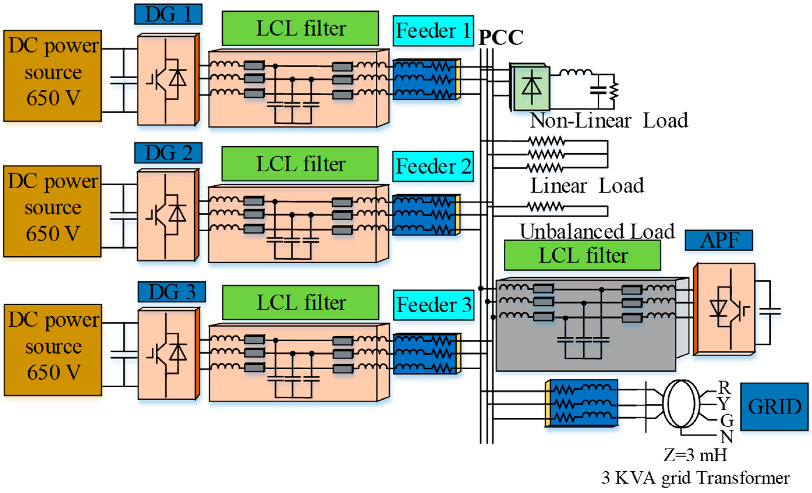
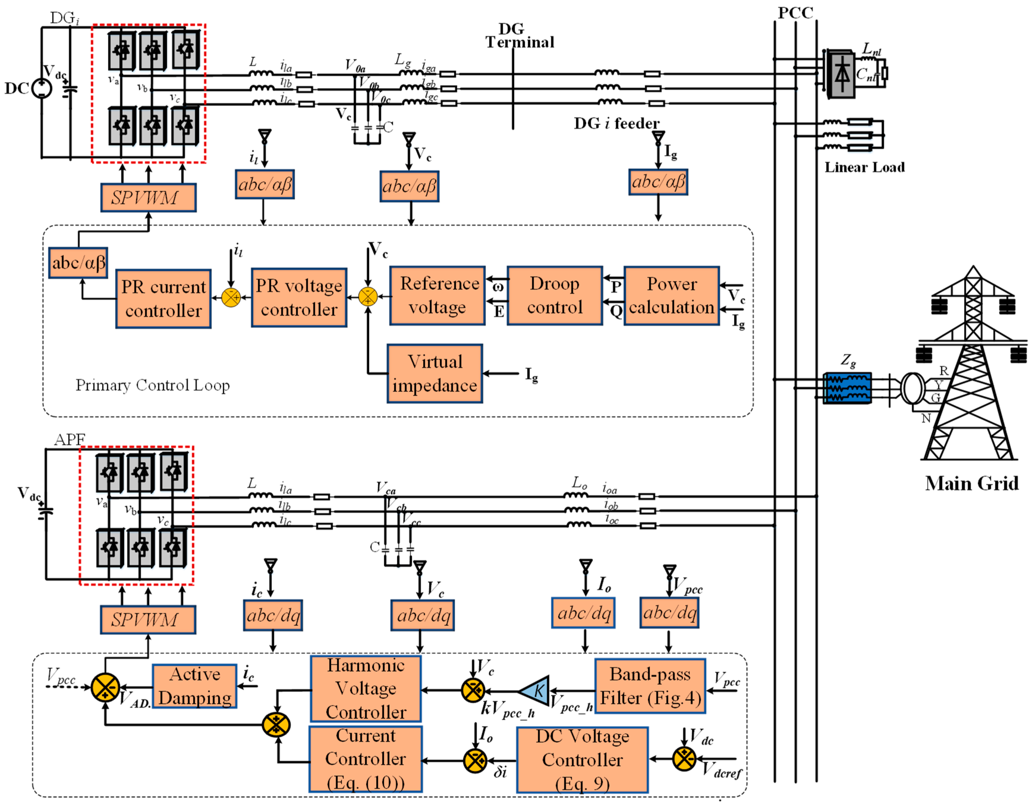
2. Control Architecture (DGs+APF)

In an AC microgrid, due to the existence of nonlinear loads and mismatched feeder impedances, the output grid current does not remain sinusoidal, which may distort the power and causes severe voltage imbalance compensation at the PCC [32]. Therefore, in this paper, we demonstrate that SAPF improves voltage quality at the PCC, as well as increasing harmonic current compensation. Before discussing the proposed harmonic compensation technique for the SAPF, which would be implemented and incorporated later on with the grid-connected control of DGs, we shall first review the conventional control of DGs and APF. Figure 2 shows the conventional voltage detection based harmonic compensation scheme for multiple grid-connected DGs at the PCC using R-APF as a power quality conditioner.
At first, the conventional control strategy for grid-connected DGs is implemented in order to deliver and inject maximum power from the DGs to the grid. Once the primary control strategy is maintained among the DGs, SAPFs are used as a power conditioning circuit to compensate the harmonics caused due to the unequal line impedances. DGs connected to the grid contain a droop controller, virtual impedance and an inner loop control scheme. The voltage and frequency variations can be maintained by utilizing a droop controller without using any communication lines among the DGs [33]. A detailed description of the primary control loop used for grid-tied DGs is given in Section 1.
Due to the poor performance of using R-APF with DGs, an improved control strategy of APF should be introduced [21]. Thus, a voltage controlled SAPF was proposed which was employed and incorporated with grid-connected DGs at the PCC as shown in Figure 3.
This configuration is considered suitable for grid-connected DGs since it can perform voltage harmonic compensation based on the existing Vpcc voltage measurement. Also, it can be easily implemented. Furthermore, there is no difficulty in calculating the virtual impedance or conductance 1/R as it was needed in the conventional control mechanism of R-APF. It is important to realize that in the traditional R-APF control, the harmonic compensation performance is subjected to large variations based on the matching constraints, which exist between the harmonic conductance (1/R) of the R-APF and the impedance characteristic of the power distribution grid. So, a comparison between both APFs is carried out with grid-connected DGs to figure out the harmonic compensation performance in case of distorted and unbalanced load conditions. The detailed classification of grid voltage and the exact extraction of equivalent harmonics under unbalanced load conditions are measured and taken as a fundamental issue for adequate harmonic compensation. Thus, the exploitation of a bandpass filter (BPF) for the extraction of harmonics appears to be a very favorable solution in APF applications, with a focus on determining the appropriate harmonic compensation gains for a fruitful harmonic compensation. The controller gains can easily be fixed regarding their phases, as well as magnitudes of the designated harmonic frequencies. The idea of using BPF for the detection of harmonics has been broadly applied due to its rapidness and precision concerning harmonic detection [8,20]. Therefore, BPF expands its detection efficiency and finally extracts the harmonic of the Vpcc when grid voltage deals high order harmonics in case of distortion. Hence, in this paper, BPF is implemented as shown in Figure 4 to evaluate the harmonics of the Vpcc to guarantee effective and precise voltage harmonic extraction.
The following expression is the transfer function of BPF expressed in z-domain:
G B P F ( z ) = K n { z 2 cos ( 2 π T s f p l l n ) z } a n z 2 b n cos ( 2 π T s f p l l n ) z ) + 1
where Kn = KinTs, an = 1 + Kn and bn = 2 + Kn, Kn denotes integral coefficient, Ts is the sampling period, and n denotes the harmonic order. The adopted BPF compensates up to 13th harmonic orders in this paper. The Bode plot of the given BPF is given in Figure 5 for a quick understanding of its performance strategy.

3. Primary Control of DG

3.1. Droop Control

To compute the instantaneous power (active and reactive) in αβ axis, a droop controller is employed. Their output voltage (Vαβ) and current (Iαβ) are implemented using the instantaneous theory [34].
[ p q ] = [ P + p 0 Q + q 0 ] = [ v α v β v β v α ] [ i α i β ]
where p shows the instantaneous active and similarly q shows the instantaneous reactive power. The active power (P) and reactive power (Q) represents the DC components at the fundamental frequency as well as at their harmonic frequencies. The (p0) and (q0) are ripple components that need to be filtered by passing through a lowpass filter (LPF). Therefore, the following expression estimates the reactive power and real power once the DC components have been filtered out using LPF with 2 Hz cut-off frequency (ωLPF). The droop controller is used to adjust and maintain voltage and frequency deviations while ensuring power flow at a DG local controller. The other purpose is to use the droop controller so that it can eliminate the need to use communication lines among the DGs.
ω = ω * k p D ( P P * )
E = E * k q D ( Q Q * )
The above expressions illustrate the active power-frequency (P-ω) and reactive power-voltage magnitude (Q-E), where ω depicts frequency and E depicts the value of amplitude voltage reference. Meanwhile, ω* and E* are rated as nominal values of frequency and amplitude. P* is denoted as the positive sequence active power, while Q* is denoted as positive sequence reactive power. kpD and kqD are the droop coefficients.

3.2. Virtual Impedance

By utilizing a virtual impedance loop, the ratio of inductance to resistance (X/R) can be adjusted with corresponding inverters output impedance in a microgrid. The virtual impedance loop is usually used to maintain the droop controller performance in the primary controller of the microgrid. The following expressions are used to calculate the virtual impedances. Furthermore, the design procedure to calculate virtual impedance, the inner voltage and control loops was proposed in Reference [35].
v v α = R v · i g α ω L v · i g β
v v β = R v · i g β ω L v · i g α

3.3. Voltage and Current Controller

The reference signals of voltage control loop are adjusted according to the virtual impedance loop. Figure 3 shows the inner double loop, which consists of voltage and current controllers. Additionally, these inner double loop controllers are based on proportional resonant controllers. They offer an appropriate control signal for the pulse width modulation (PWM) module to produce an equivalent output voltage for DGs in the system. The design procedure of the proportional resonant controllers is discussed in [36]. The Equations (7) and (8) shows the transfer functions of the corresponding voltage and current controllers, respectively.
G v ( s ) = k p ω + ( h = 1 , 5 , 7 , 11 , 13 , ........ ) 2 k i ω ω c n s s 2 + 2 ω c n s + ( 2 π h f ) 2
G i ( s ) = k   ( h = 1 , 5 , 7 , 11 , 13 , ........ ) 2 k i E ω c n s s 2 + 2 ω c n s + ( 2 π   h f ) 2 p E
where k and kpE represent the proportional resonant gains for voltage and current controllers while ωcn is the cut-off frequency of these resonant controllers bandwidth.

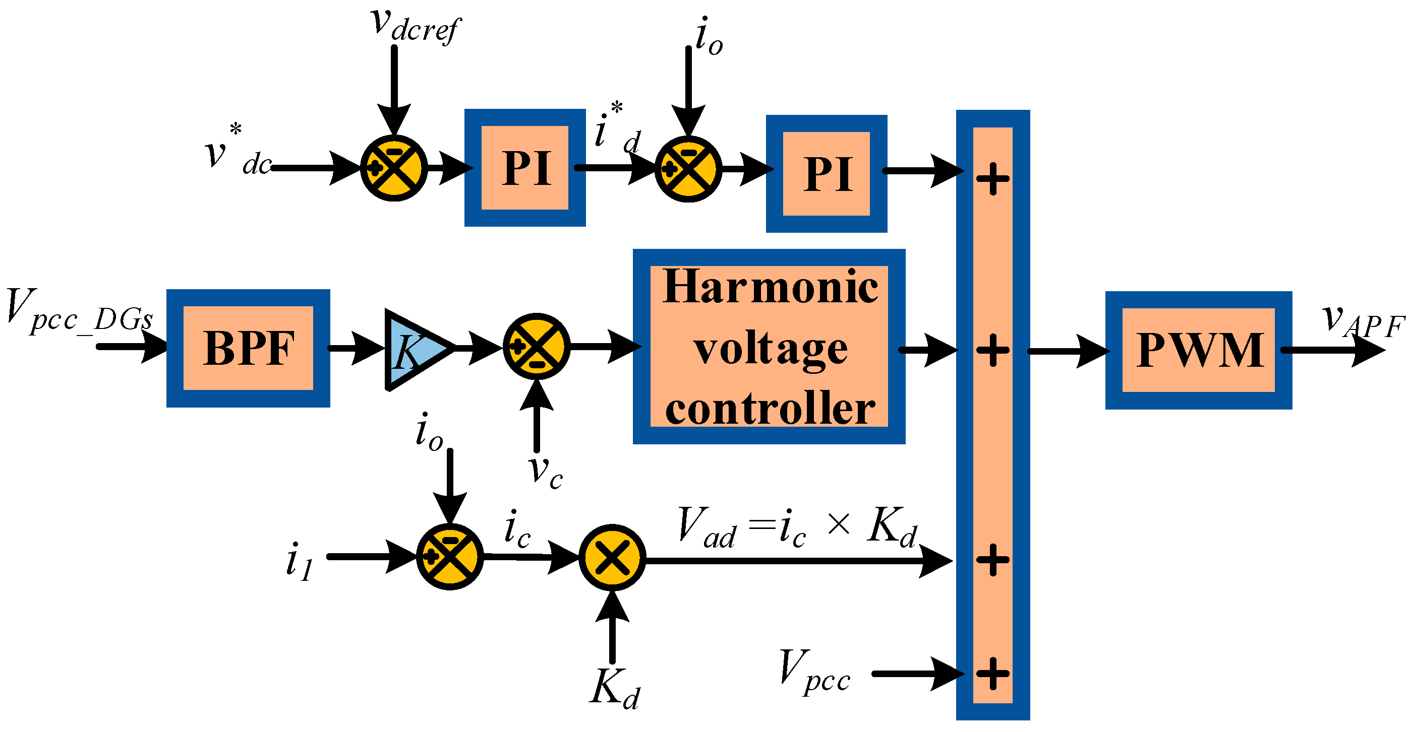
4. Design Procedure of the Voltage Controlled APF

If the PCC voltage gets distorted due to the presence of nonlinear loads in the case of multiple grid-connected converters, then harmonic filtering can be done using the SAPF. Figure 6 describes the control layout of the proposed APF. The cooperation of APF with grid-connected DGs can be achieved at the PCC. Under distorted load conditions and severe unbalance voltage harmonic compensation, the SAPF uses the local based Vpcc voltage and passes it through the BPF as shown in Figure 3. The BPF calculates the harmonics of Vpcc and extracts up to the 13th order harmonics in this paper. Later on, multiplying the harmonics of Vpcc as represented by “Vpcc” with the compensation gain K, the harmonic reference voltage can be achieved. After that, the capacitor voltage of the filter “Vc” is subtracted from KVpcc in order to generate an error signal that could be fed into a harmonic voltage compensation controller. It is notable that filter capacitor voltage can be considered as a feedback control signal which helps in regulating the PCC voltage. Based on an array of multiple resonant controllers, the harmonic voltage compensation controller is used to compensate multiple order harmonics. Consequently, an improved harmonic compensation of voltage and grid current are achieved.
Furthermore, the harmonic compensation control loop for the proposed APF includes four parts, which are the DC voltage control loop, current control loop, harmonic voltage compensation control loop, and active damping control loop [21]. It is briefly studied as follows:

4.1. DC Voltage Controller

The DC voltage loop is designed based on a PI controller to maintain a constant DC voltage. The DC capacitor voltage is subtracted from the DC voltage reference. Moreover, the resulted error is processed in the PI controller to keep the DC constant voltage level. Following expression represents the transfer function of the DC voltage loop.
G c ( s ) = 1 / ( s C d c )

4.2. Fundamental Current Control Loop

The current controller has a fundamental ability to track the positive sequence and negative sequence reference currents without any steady state error. The current controller has a main function of controlling and formulating fundamental power flow, giving unity power factor output current to the grid, thus assuring the system stability. The following expression represents the PI controller:
G P I ( s ) = K p   ( 1 + 1 T i c   ( s ) )
where Kp is assumed to be as controller gain which can be tuned according to the crossover frequency.

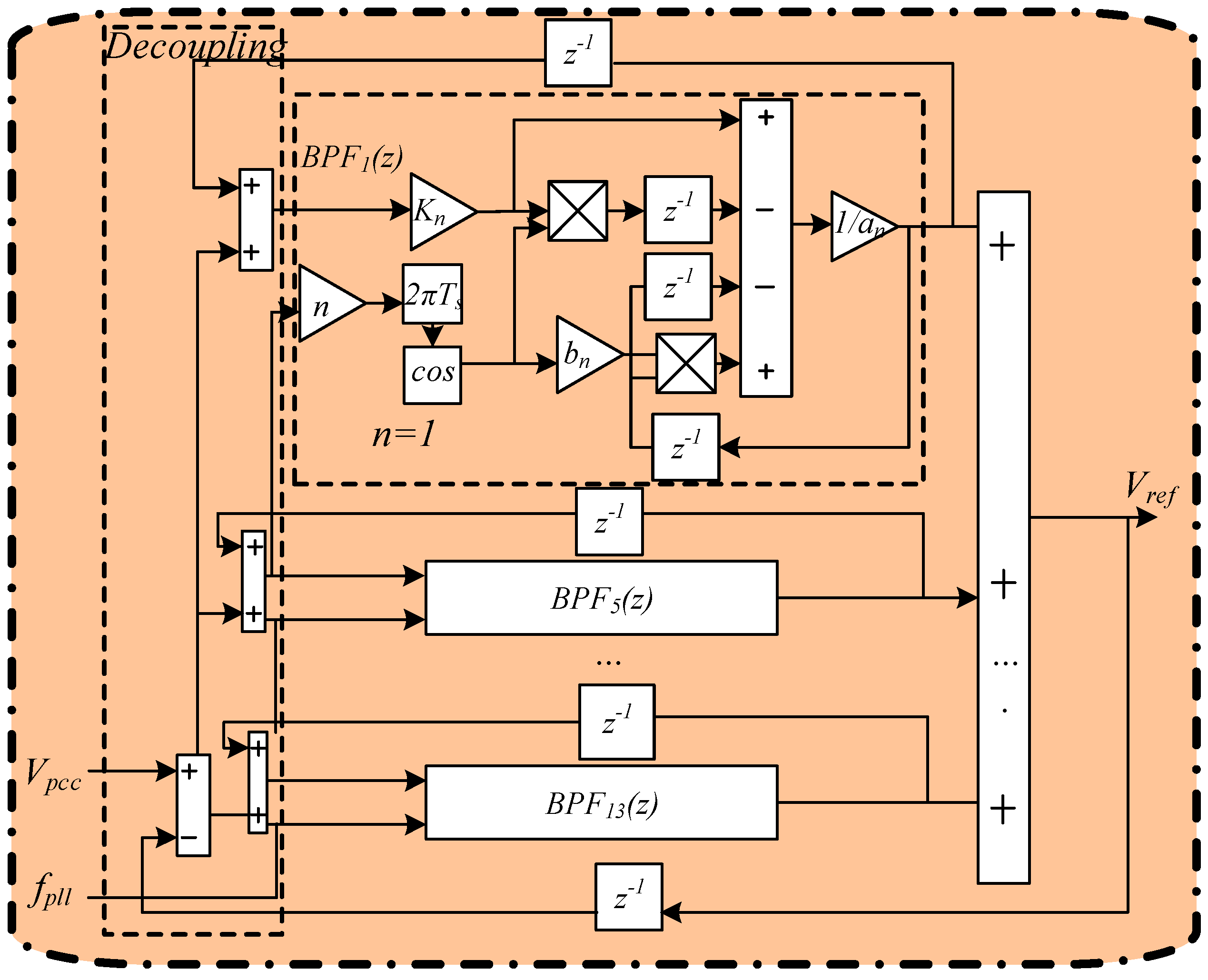
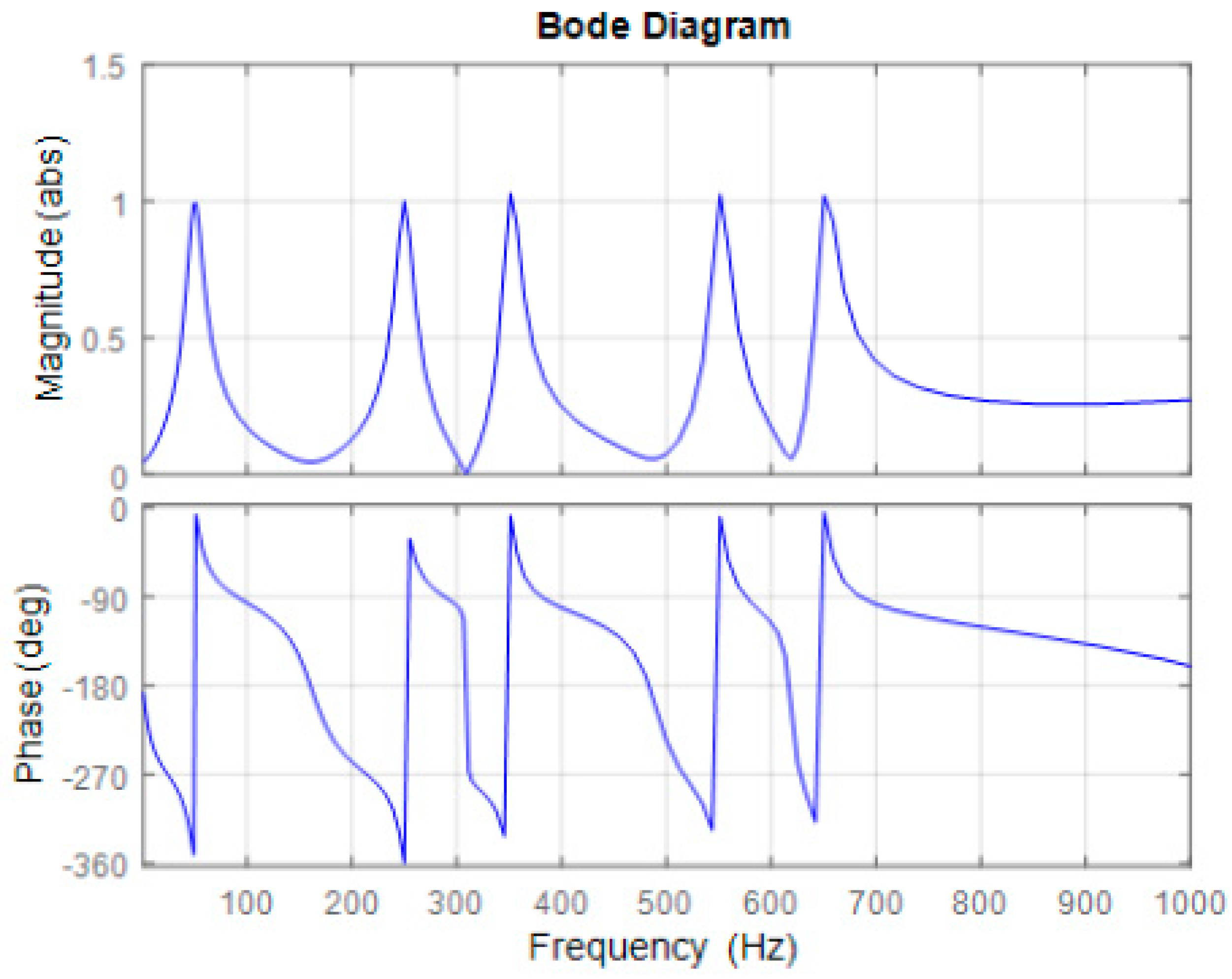
4.3. Harmonic Voltage Control Loop

In this paper, the harmonic voltage control loop uses the resonant controllers to compensate the harmonic compensation.
G r ( s ) = h = 3 , 5 , 7 , 11 , 13 , ..... k r cos φ h ω sin φ s 2 + ( h ω ) 2
where kr represents the resonant controller gain, h shows the harmonic order, and φ defines the phase lead angle taken at the resonant frequency.

4.4. Active Damping Compensation Control Loop

To reduce damping of the resonance effect of oscillations of the LCL filter, an active damping loop is introduced that will stabilize the system. The capacitor current feedback of the LCL filter is used to suppress the filter resonance peaks. Therefore, by properly designing the capacitor current feedback gain, the system can be made stable, i.e., free from oscillations. ic is the capacitor current, and Kd is the capacitor current feedback gain.
V A D = i c × K d

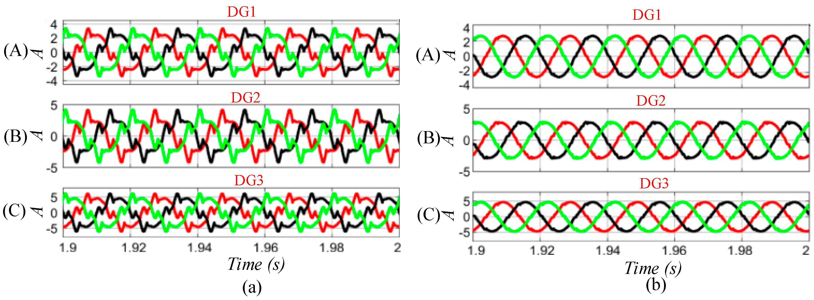
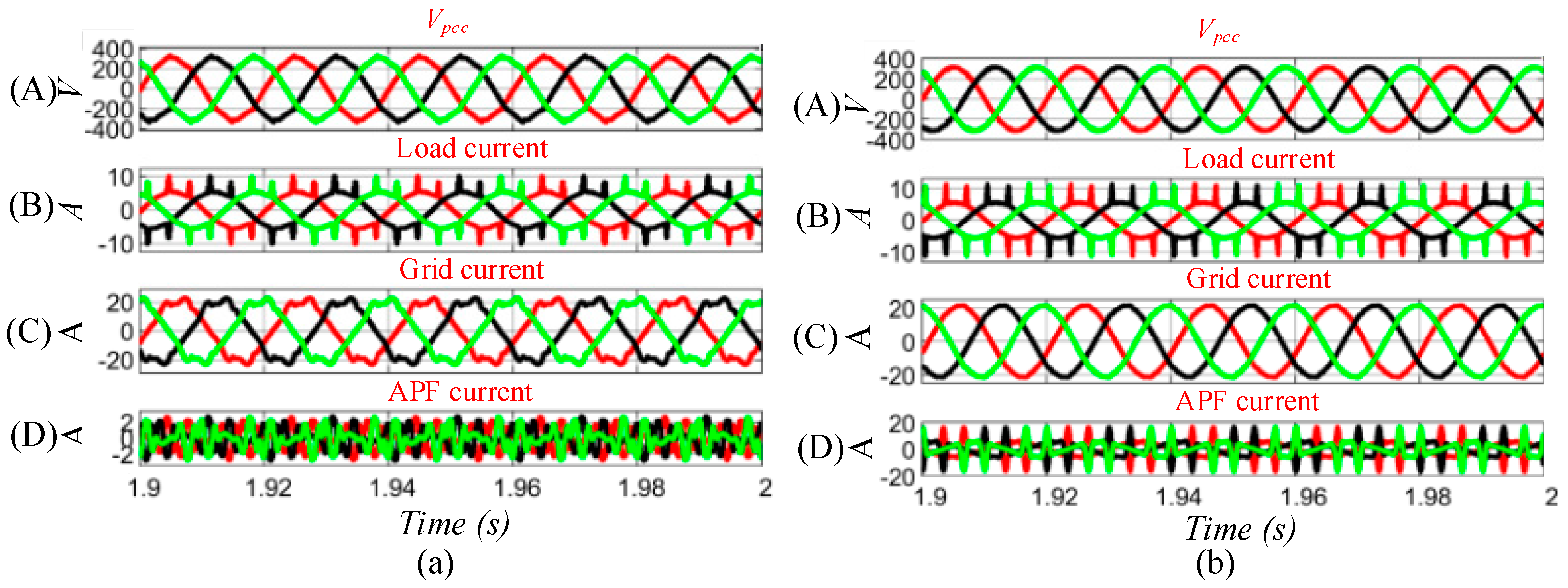
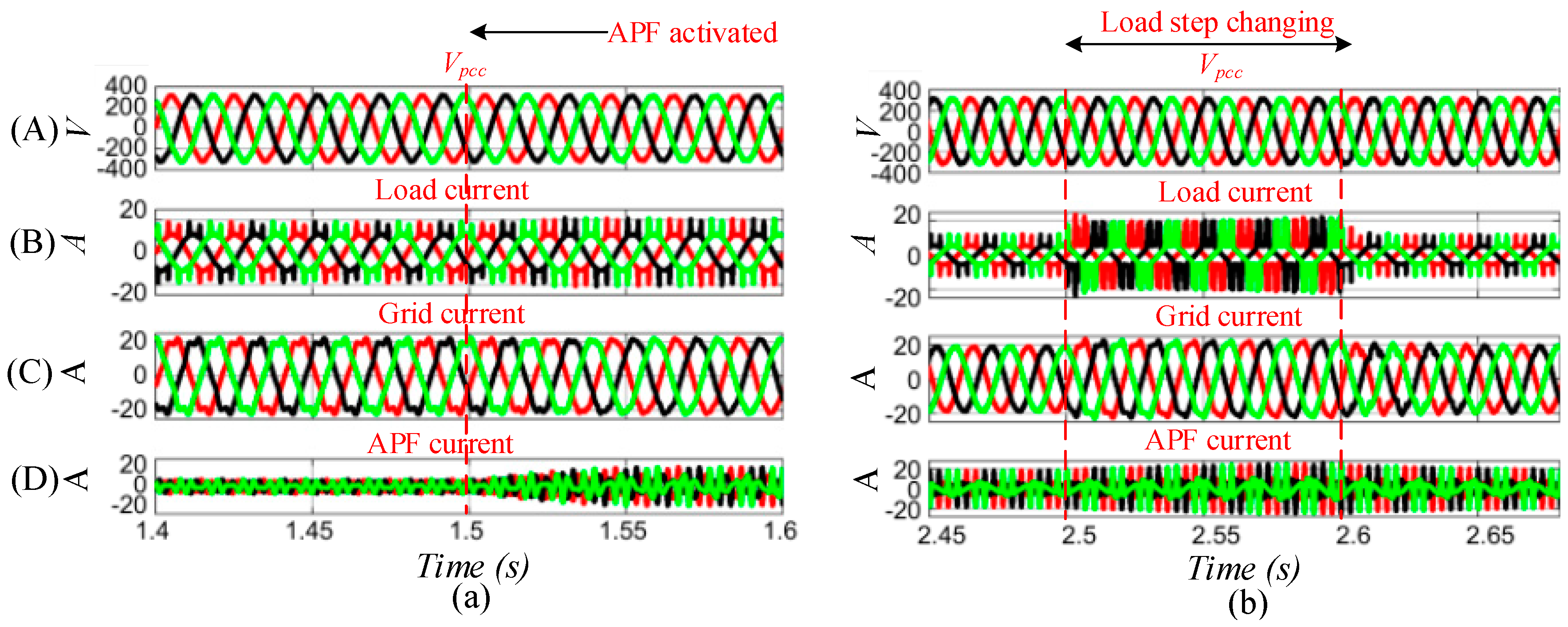
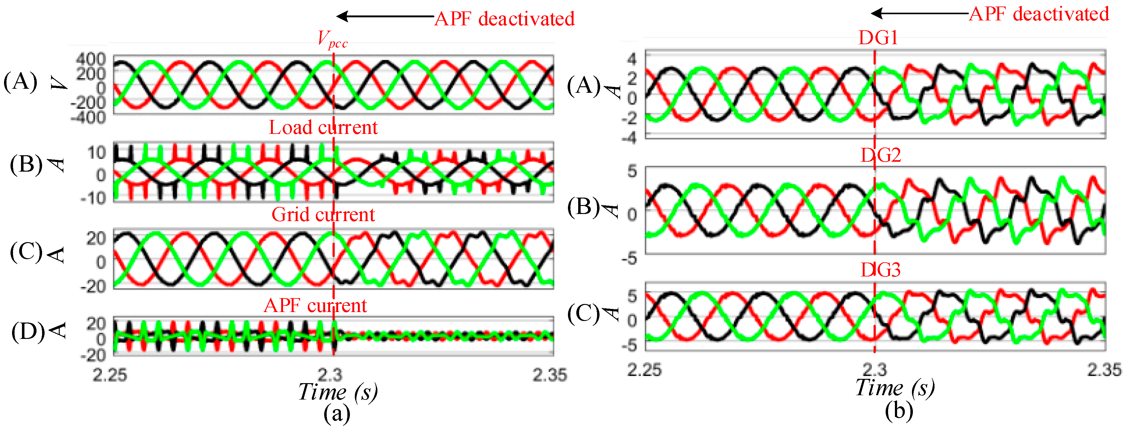
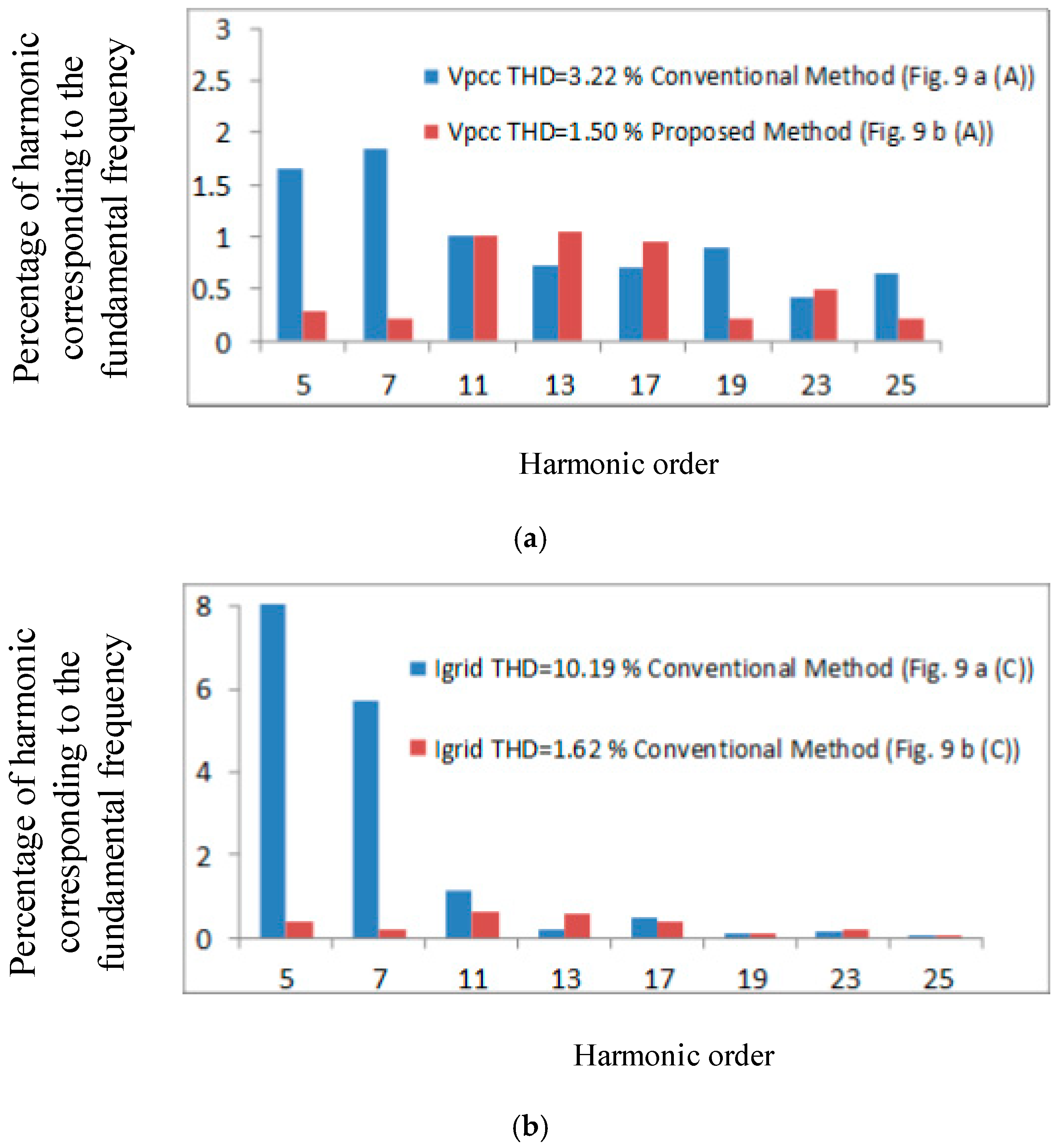
5. Comparative Simulations

The proposed study was conducted using MATLAB/Simulink with the configurations as seen in Figure 3. Moreover, the three paralleled DGs and APF are connected to the grid through the LCL filter at the PCC. The compensation of both CCM and VCM SAPF with multiple grids connected DGs have been carried out for unbalancing of the voltage compensation. Table 1 and Table 2 show the specifications for the power stage and control system parameters, respectively. In order to emulate the nonlinear load, a three-phase diode rectifier followed by an inductor filter with the value of 300 µH and a resistor with the value of 50 Ω is connected to the PCC. The system parameters for both the cases of CCM and VCM are same, as shown in Figure 2 and Figure 3.
For the sake of comparison, Figure 7 illustrates the output currents waveforms of the associated grid-connected DGs in order to analyze the performance in steady-state for conventional control of the DGs and APF compared with the proposed control of the DGs and APF. Figure 7b depicts that in case of the proposed method, DGs current waveforms seem more sinusoidal as compared to the conventional control of the DG and R-APF. As shown in Figure 7a, DGs currents are more distorted when it takes into account the study of the conventional control of DGs and APF. The THDs of their DGs currents are 23.95%, 31.03%, and 26.62% for DG1, DG2, and the DG3, respectively, after its compensation is enabled. But later on, in Figure 7, the DGs currents are more sinusoidal and balanced by virtue of the proposed cooperative control of the DGs and APF. The THDs of the grid-connected DGs currents have considerably decreased, and are calculated as 3.74%, for DG1, 4.78% for DG2, and 4.38% for DG3. The proposed control strategy shows its effectiveness as it brings the THDs of the DGs currents to less than 5%, which also satisfies the IEEE 1547 standards [37].
Figure 8 depicts the comparative analysis of the steady-state performances of the conventional grid-connected DGs with R-APF over the grid-connected DGs with our proposed APF in which the waveforms of the grid voltage, load current, grid current, and APF are shown. It is obvious from Figure 8 that PCC voltage, load current, and grid currents are more distorted and are not appropriately compensated due to limited compensation performance of R-APF with grid-connected DGs. Whereas, in the later approach as shown in Figure 8, which is our proposed control of the DG and APF, the PCC voltage, load current, and grid current have been compensated remarkably. As a result, the THD values of the grid voltage and grid currents have been improved significantly, which are 2.28% and 1.62%, respectively.
The simulation results of the proposed APF operation which is used to cooperate with grid-connected DGs under normal conditions is shown in Figure 9. As a result of voltage harmonics compensation around 1.5 s, the APF is activated, and the PCC harmonic voltage pollution is considerably scaled down and the corresponding grid current is significantly improved from distorted non-linear to linear, balanced, and clean sinusoidal current. Consequently, the THD values of the corresponding voltage and grid current are effectively reduced. THD of the Vpcc and grid currents in the conventional method were 9.97% and 11.98% while in the proposed method as demonstrated in Figure 9, the THD values of the PCC voltage and grid currents are now improved to 2.28% and 1.07%, respectively. Figure 9b shows the dynamic waveforms in case of sudden step change in the load, which is from half to full and from full to half-load during an interval from 1.95–2.05 s. During that time, Vpcc and grid current profiles remain sinusoidal.
Similarly, in Figure 10b, the dynamic response of DGs current is illustrated. When the APF was in operation, the DGs currents were balanced and sinusoidal, but as soon as the APF is suddenly deactivated, the DGs currents will no longer be sinusoidal and will become highly distorted. Thus, the proposed control architecture is more efficient in operation both in the steady-state as well in the dynamic state. However, the comparison of THD values for harmonic analysis of PCC voltage of the conventional and the proposed method is given in Figure 11a whereas for the grid current is depicted in Figure 11b.
From the results shown above, it is evident that the proposed APF with the DGs offers better harmonic compensation capability. Table 3 shows the comparison of conventional and the proposed control schemes listing out its output DGs voltages and Vpcc THDs.

6. Conclusions

In this paper, control architecture of the newly proposed VCM-SAPF has been proposed to cooperate with grid-connected DGs to compensate voltage imbalance and harmonic distortion issues. The proposed VCM-APF contains an embedded voltage harmonic compensator, which can be seamlessly integrated with the DGs. In addition, this approach has the advantage of easy implementation as it can be operated on the basis of direct voltage detection at PCC. The cooperation of the VCM-APF with the DGs is made in such a way that in case of unbalanced voltage compensation, the proposed APF will cooperate with the DGs to provide compensation. A comparison of the proposed technique with the conventional RAPF-based cooperated control strategy for DGs was provided, using simulation results in MATLAB/Simulink where it has been investigated that the quality of the grid current has been improved remarkably compared with the conventional approach. Therefore, we concluded that the proposed scheme offers better harmonic compensation performance, avoiding the need of taking a remote load current measurement, as well as avoiding the calculation of the parameter values of virtual impedance, which is sometimes considered not as easy task owing to the dispersed nature of the DG. Moreover, the steady state and dynamic operation of VCM-APF in grid-connected DGs have demonstrated excellent performance.

Author Contributions

The research study was carried out successfully with the contribution from all authors.

Funding

This work was supported by the National Natural Science Foundation of China under Grant 51807021 and 51707030, and the Sichuan Science and technology support program under Grant 2017GZ0051.

Acknowledgments

The authors would like to thank Yang Han for his kindness, moral support and all the inspiring discussions throughout this project. Special thanks to Rami Ghannam and Abu Bakar to contribute their efforts in reviewing and editing the manuscript. Finally, the authors would also like to thank the anonymous reviewers and editors for their insightful comments and feedback which helped to improve this manuscript.

Conflicts of Interest

The authors declare no conflict of interest.

References

  1. Ebadian, M.; Talebi, M.; Ghanizadeh, R. A new approach based on instantaneous power theory for improving the performance of UPQC under unbalanced and distortional load conditions. Automatika 2015, 56, 226–237. [Google Scholar] [CrossRef]
  2. Singh, B.; Haddad, A.; Chandra, A. A review of active filters for power quality improvement. IEEE Trans. Ind. Electron. 1999, 46, 960–971. [Google Scholar] [CrossRef] [Green Version]
  3. Boukezata, B.; Chaoui, A.; Gaubert, J.P.; Hachemi, M. Power quality improvement by an active power filter in grid-connected photovoltaic systems with optimized direct power control strategy. Electr. Power Compon. Syst. 2016, 44, 2036–2047. [Google Scholar] [CrossRef]
  4. Dionise, T.J.; Lorch, V. Voltage distortion on an electrical distribution system. IEEE Ind. Appl. Mag. 2010, 16, 48–55. [Google Scholar] [CrossRef]
  5. Akagi, H. New trends in active Filters for power conditioning. IEEE Trans. Ind. Appl. 1996, 32, 1312–1322. [Google Scholar] [CrossRef]
  6. Khadem, S.K.; Basu, M.; Conlon, M.F. Intelligent islanding and seamless reconnection technique for microgrid with UPQC. IEEE J. Emerg. Sel. Top. Power Electron. 2015, 3, 483–492. [Google Scholar] [CrossRef]
  7. Jintakosonwit, P.; Fujita, H.; Akagi, H.; Ogasawara, S. Implementation and performance of cooperative control of shunt active filters for harmonic damping throughout a power distribution system. IEEE Trans. Ind. Appl. 2003, 39, 556–564. [Google Scholar] [CrossRef]
  8. Xie, C.; Zhao, X.; Savaghebi, M.; Meng, L.; Guerrero, J.M.; Vasquez, J.C. Multi-Rate Fractional-Order Repetitive Control of Shunt Active Power Filter. IEEE J. Emerg. Sel. Top. Power Electron. 2016, 5, 809–819. [Google Scholar] [CrossRef]
  9. Khadem, S.K.; Basu, M.; Conlon, M.F. Parallel operation of inverters and active power filters in distributed generation system—A review. Renew. Sustain. Energy Rev. 2011, 15, 5155–5168. [Google Scholar] [CrossRef] [Green Version]
  10. Green, T.C.; Marks, J.H. Control techniques for active power filters. IEE Proc. Electr. Power Appl. 2005, 152, 369–381. [Google Scholar] [CrossRef]
  11. Hashempour, M.M.; Lee, T.L. Integrated Power Factor Correction and Voltage Fluctuation Mitigation of Microgrid Using STATCOM. In Proceedings of the 2017 IEEE 3rd International Future Energy Electronics Conference and ECCE Asia (IFEEC 2017—ECCE Asia), Kaohsiung, Taiwan, 3–7 June 2017; pp. 1215–1219. [Google Scholar]
  12. Tareen, W.U.K.; Mekhielf, S. Three-Phase Transformerless Shunt Active Power Filter with Reduced Switch Count for Harmonic Compensation in Grid-Connected Applications. IEEE Trans. Power Electron. 2018, 33, 4868–4881. [Google Scholar] [CrossRef]
  13. Menniti, D.; Burgio, A.; Pinnarelli, A.; Sorrentino, N. Grid-interfacing active power filters to improve the power quality in a microgrid. In Proceedings of the 13th International Conference on Harmonics and Quality of Power, Wollongong, NSW, Australia, 28 September–1 October 2008; pp. 1–6. [Google Scholar]
  14. Mindykowski, J.; Xiaoyan, X.; Tarasiuk, T. A new concept of harmonic current detection for shunt active power filters control. Meas. J. Int. Meas. Confed. 2013, 46, 4334–4341. [Google Scholar] [CrossRef]
  15. Yeetum, W.; Kinnares, V. Parallel Active Power Filter Based on Source Current Detection for Anti-Parallel Resonance with Robustness to Parameter Variations in Power Systems. IEEE Trans. Ind. Electron. 2019, 66, 876–886. [Google Scholar] [CrossRef]
  16. Hashempour, M.M.; Savaghebi, M.; Vasquez, J.C.; Guerrero, J.M. A control architecture to coordinate distributed generators and active power filters coexisting in a microgrid. IEEE Trans. Smart Grid 2016, 7, 2325–2336. [Google Scholar] [CrossRef]
  17. He, J.; Li, Y.W.; Munir, M.S. A flexible harmonic control approach through voltage-controlled DG-grid interfacing converters. IEEE Trans. Ind. Electron. 2012, 59, 444–455. [Google Scholar] [CrossRef]
  18. Nagarapu, S.; Khamuruddin, S.; Kumaraswamy, D. Grid Interconnection of Renewable Energy Sources with Power-Quality Improvement Features. IEEE Trans. Power Deliv. 2010, 3, 23–28. [Google Scholar]
  19. Zhao, X.; Meng, L.; Xie, C.; Guerrero, J.M.; Wu, X.; Vasquez, J.C.; Savaghebi, M. A voltage feedback based harmonic compensation strategy for current-controlled converters. IEEE Trans. Ind. Appl. 2018, 54, 2616–2627. [Google Scholar] [CrossRef]
  20. Zhao, X.; Meng, L.; Xie, C.; Guerrero, J.M.; Wu, X. A Unified Voltage Harmonic Control Strategy for Coordinated Compensation with VCM and CCM Converters. IEEE Trans. Power Electron. 2018, 33, 7132–7147. [Google Scholar] [CrossRef]
  21. Munir, H.M.; Zou, J.; Xie, C.; Li, K.; Zhao, X.; Guerrero, J.M. Direct harmonic voltage control strategy for shunt active power filter. In Proceedings of the IECON 2017—43rd Annual Conference of the IEEE Industrial Electronics Society, Beijing, China, 29 October–1 November 2017; pp. 1101–1106. [Google Scholar]
  22. Noroozian, R.; Gharehpetian, G.B. An investigation on combined operation of active power filter with photovoltaic arrays. Int. J. Electr. Power Energy Syst. 2013, 46, 392–399. [Google Scholar] [CrossRef]
  23. Rahmani, S.; Hamadi, A.; Al-Haddad, K.; Dessaint, L.A. A combination of shunt hybrid power filter and thyristor-controlled reactor for power quality. IEEE Trans. Ind. Electron. 2014, 61, 2152–2164. [Google Scholar] [CrossRef]
  24. Han, B.; Bae, B.; Kim, H.; Baek, S. Combined operation of unified power-quality conditioner with distributed generation. IEEE Trans. Power Deliv. 2006, 21, 330–338. [Google Scholar] [CrossRef]
  25. Li, Y.W.; He, J. Distribution system harmonic compensation methods: An overview of DG-interfacing inverters. IEEE Ind. Electron. Mag. 2014, 8, 18–31. [Google Scholar] [CrossRef]
  26. Tareen, W.; Aamir, M.; Mekhilef, S.; Nakaoka, M.; Seyedmahmoudian, M.; Horan, B.; Memon, M.; Baig, N. Mitigation of power quality issues due to high penetration of renewable energy sources in electric grid systems using three-phase APF/STATCOM technologies: A review. Energies 2018, 11, 1491. [Google Scholar] [CrossRef]
  27. He, J.; Li, Y.W.; Blaabjerg, F.; Wang, X. Active harmonic filtering using current-controlled, grid-connected DG units with closed-loop power control. IEEE Trans. Power Electron. 2014, 29, 642–653. [Google Scholar]
  28. Sun, X.; Han, R.; Shen, H.; Wang, B.; Lu, Z.; Chen, Z. A double-resistive active power filter system to attenuate harmonic voltages of a radial power distribution feeder. IEEE Trans. Power Electron. 2016, 31, 6203–6216. [Google Scholar] [CrossRef]
  29. He, J.; Member, S.; Li, Y.W.; Member, S.; Bosnjak, D.; Harris, B. Investigation and Active Damping of Multiple Resonances in a Parallel-Inverter-Based Microgrid. IEEE Trans. Power Electron. 2013, 28, 234–246. [Google Scholar] [CrossRef]
  30. Wang, X.; Zou, J.; Zhao, J.; Xie, C.; Li, K.; Munir, H.; Josep, M.G. A Novel Model Predictive Control Strategy to Eliminate Zero Sequence Circulating Current in Paralleled Three-Level Inverters. IEEE J. Emerg. Sel. Top. Power Electron. 2018. [Google Scholar] [CrossRef]
  31. Xie, C.; Zhao, X.; Li, K.; Zou, J.; Josep, M.G. A New Tuning Method of Multi-Resonant Current Controllers for Grid-Connected Voltage Source Converters. IEEE J. Emerg. Sel. Top. Power Electron. 2018. [Google Scholar] [CrossRef]
  32. Li, H.; Han, Y.; Yang, P.; Xiong, J.; Wang, C. A Proportional Harmonic Power Sharing Scheme for Hierarchical Controlled Microgrids Considering Unequal Feeder Impedances and Nonlinear Loads. In Proceedings of the 2017 IEEE Energy Conversion Congress and Exposition (ECCE), Cincinnati, OH, USA, 1–5 October 2017; pp. 5–9. [Google Scholar]
  33. Mousavi, S.Y.; Jalilian, A.; Savaghebi, M.; Ge, J.M. Autonomous control of current and voltage controlled DG interface inverters for reactive power sharing and harmonics compensation in islanded microgrids. IEEE Trans. Power Electron. 2018, 33, 9375–9386. [Google Scholar] [CrossRef]
  34. Lee, T.L.; Cheng, P.T. Design of a new cooperative harmonic filtering strategy for distributed generation interface converters in an islanding network. IEEE Trans. Power Electron. 2007, 22, 1919–1927. [Google Scholar] [CrossRef]
  35. He, J.; Li, Y.W. Analysis, design, and implementation of virtual impedance for power electronics interfaced distributed generation. IEEE Trans. Ind. Appl. 2011, 47, 2525–2538. [Google Scholar] [CrossRef]
  36. Yepes, A.G.; Freijedo, F.D.; López, Ó.; Doval-Gandoy, J. Analysis and design of resonant current controllers for voltage-source converters by means of Nyquist diagrams and sensitivity function. IEEE Trans. Ind. Electron. 2011, 58, 5231–5250. [Google Scholar] [CrossRef]
  37. Basso, T.S.; DeBlasio, R. IEEE 1547 series of standards: Interconnection issues. IEEE Trans. Power Electron. 2004, 19, 1159–1162. [Google Scholar] [CrossRef]
Figure 1. A general diagram of the proposed study.
Sustainability 11 00154 g001
Figure 2. The conventional control diagram of DGs and active power filter (APF).
Sustainability 11 00154 g002
Figure 3. Proposed control diagram of distributed generators (DGs) and APF.
Sustainability 11 00154 g003
Figure 4. The extraction of harmonics based on the bandpass filter (BPF) filter second order generalized integrator.
Sustainability 11 00154 g004
Figure 5. The Bode plot of the BPF filter (GBPF).
Sustainability 11 00154 g005
Figure 6. The internal control architecture of APF.
Sustainability 11 00154 g006
Figure 7. Steady-state DGs current waveforms after enabling the APF. (a) Control of DGs with traditional R-APF; (b) control of DGs with the proposed voltage-controlled mode (VCM)-APF.
Sustainability 11 00154 g007
Figure 8. Steady-state voltages and current waveforms after enabling the APF. (a) Control of DGs with traditional R-APF; (b) Control of DGs with proposed VCM-APF. (A) point of common coupling (PCC) voltage; (B) load current; (C) grid current; (D) APF current.
Sustainability 11 00154 g008
Figure 9. Dynamic performance of the proposed VCM-APF in grid-connected DGs. (a) Activation of APF; (b) load transition.
Sustainability 11 00154 g009
Figure 10. The dynamic performance of the proposed study. (a) When APF is deactivated at 2.3 s; (b) when the DGs currents get distorted after deactivating the proposed APF.
Sustainability 11 00154 g010
Figure 11. A comparison of the two control schemes (a) Vpcc voltage and (b) Grid current.
Sustainability 11 00154 g011
Table 1. System Parameters.
System ParametersValue
Grid voltage220 V/50 Hz
Grid feederLg = 3.3 mH, Rg = 0.15 Ω
Switching frequency (f), Nominal Voltage (V)f = 10 kHz, V = 230 V
Reference DC link voltage650 V
DGs
Input and output filter inductances + filter capacitors of DGsL and Lg = 1.8 mH, C = 9 µF
Physical DG feedersDG1 feeder inductance LDG1 = 6 mH,
DG1 feeder resistance RDG1 = 0.3 Ω; DG2 feeder inductance LDG2 = 4 mH, DG2 feeder resistance RDG2 = 0.25 Ω; DG3 feeder inductance LDG3 = 2 mH, DG3 feeder resistance RDG3 = 0.15 Ω
Load ParametersValue
Linear LoadR = 1 × 10⁻³ Ω, L = 10 × 10−3 H
Non-linear LoadLNL = 300 × 10−6 H, CNL = 250 × 10−6 F, RNL = 50 Ω
Unbalanced LoadR = 230 Ω
APF
System ParametersValue
LCL filter (APF converter)Converter side inductor L = 1.8 mH, Parasitic resistance of L (R1 = 200 mΩ)
Grid Side Inductor Lo = 0.9 mH, Parasitic resistance of Lo (R2 = 0.4 mΩ) Capacitor Cf = 9 µF
Load ParametersValue
Non-Linear LoadDC Smoothing inductor, LL = 1.8 mH
DC Load, RL = 150Ω
Table 2. Control Parameters.
Voltage and Current LoopsValue
Kp, Ki, ωhi, ω0.175, 1.25, 5, 100 pi
Kih(h = −5) 50, (h = 7) 40, (h = −11) 20, (h = 13) 20 and (h = −17) 10
Power Control ParametersValue
Active power and reactive power controldp1 = 1 × 10⁻⁴, dq1 = 1 × 10⁻⁴; dp2 = 5 × 10⁻⁵, dq2 = 5 × 10⁻⁵; dp3 = 1 × 10⁻⁴, dq3 = 1 × 10⁻⁴
Virtual harmonic resistanceRv = 2 Ω, Lv = 6 mH
Table 3. Output DGs voltages and Vpcc THDs under different conditions.
Test StepsTotal Harmonic Distortion (THD) %
(DGs with traditional R-APF)DG1 currentDG2 currentDG3 currentVpcc voltageGrid current Ig
23.95%31.03%26.62%3.22%10.19%
(DGs with proposed-APF)DG1 currentDG2 currentDG3 currentVpcc voltageGrid current Ig
3.74%4.78%4.38%2.28%1.62%

