Article

Optimizing the Design of a Vertical Ground Heat Exchanger: Measurement of the Thermal Properties of Bentonite-Based Grout and Numerical Analysis

Department of Energy and Resources Engineering, Kangwon National University, Chuncheon 24341, Korea
*
Author to whom correspondence should be addressed.
Sustainability 2018, 10(8), 2664; https://doi.org/10.3390/su10082664
Submission received: 27 June 2018 / Revised: 20 July 2018 / Accepted: 27 July 2018 / Published: 29 July 2018

Abstract

:
We prepared bentonite-based grouts for use in the construction of vertical ground heat exchangers (GHEs) using various proportions of silica sand as an additive, and measured the thermal conductivity (TC) and specific heat capacity (SHC) of the grouts under saturated conditions. Furthermore, we performed numerical simulations using the measured thermal properties to investigate the effects of grout-SHCs, the length of the high-density polyethylene (HDPE) pipe, the velocity of the working fluid, and the operation time and off-time during intermittent operation on performance. Experimentally, the grout TCs and SHCs were in the ranges 0.728–1.127 W/(mK) and 2519–3743 J/(kgK), respectively. As the proportions of bentonite and silica sand increased, the TC rose and the SHC fell. Simulation showed that, during intermittent operation, not only a high grout TC but also a high SHC improved GHE performance. Also, during both continuous and intermittent operation, GHE performance improved as the working fluid velocity increased, and there was a critical working fluid velocity that greatly affected the performance of the vertical GHE, regardless of operation mode, high-density polyethylene (HDPE) pipe length, or grout thermal properties; this value was 0.3 m/s. Finally, during intermittent operation, depending on the operation time and off-time, critical periods were evident when the ground temperature had been almost completely restored and any beneficial effect of intermittent operation had almost disappeared.

1. Introduction

Given the depletion of fossil energy and the need to reduce the carbon footprint, interest in new and renewable energy techniques has increased worldwide. Of the various renewable energy systems currently available, ground source heat pump (GSHP) systems have been widely used because of their efficiency, energy conservation, and low-level emissions [1,2,3]. Worldwide, GSHP capacity increased 1.52-fold from 2010 to 2015 at a compound annual rate of 8.69% [4].
GSHP systems are composed of a heat pump coupled with a GHE. The GHE, which is the most important component of the GSHP system, can be either vertical or horizontal in form, and exchanges heat with the ground by circulating a working fluid within a vertical or horizontal closed-loop HDPE pipe to transfer heat to/from the ground. Vertical GHEs, placed in boreholes of diameter 0.1–0.2 m and depth 20–200 m, usually afford better thermal performance than horizontal GHEs, and have been more widely used throughout the world [5,6,7,8,9].
When installing a vertical GHE, the empty space in the borehole is backfilled with grout. This prevents collapse of the borehole and contamination of the groundwater and aquifer, and enhances the thermal contact between the GHE and the ground [10]. GSHP performance is strongly affected by the thermal properties of the ground and grout, especially the TC of the grout [11]. However, neat bentonite–water or cement–water mixes, which are commonly used as grouts, exhibit relatively low TC. Various efforts have been made to solve this problem by mixing grout with additives to achieve superior TC.
Remound and Lund [12] reported that the use of quartzite sand as an additive improved the TC of bentonite-based grout. Lee et al. [13] measured the TC and viscosity of bentonite-based grouts using silica sand or graphite as an additive, and found that as the additive content increased, the TC rose, but the viscosity also increased. Allan and Philippacopoulos [14] evaluated the thermal, mechanical, and hydraulic properties of cement-based grouts, and developed a grout mix (MIX 111) containing silica sand. Lee et al. [15] developed a cement grout containing silica sand and graphite that afforded a TC of 2.6 W/(mK) when evaluated via in situ thermal response testing (TRT).
Numerical modeling, which is widely used to solve complex problems, has been employed in many studies to predict the performance of GSHP systems. Esen et al. [16] simulated the temperature distributions in boreholes of a vertical GHE using a two-dimensional (2D) finite element model. Lee et al. [17] simulated in situ TRT using a three-dimensional (3D) finite element model of a vertical GHE. The in situ TRT and numerical simulation results were in good agreement at a ground TC of 4 W/(mK). Jalaluddin and Miyara [18] numerically evaluated the thermal performances of three types of vertical GHEs operating in different modes. Intermittent operation improved GHE performance and may allow borehole depth to be reduced. Choi et al. [19] numerically investigated the effect of varying the thermal properties of partially saturated soil on the intermittent operation of vertical GHE. Li et al. [20] numerically evaluated the performance of vertical GHE with various HDPE pipe diameters and borehole parameters. As the borehole diameter increased or the borehole depth decreased, the influence of thermal interference was reduced. Bidarmaghz et al. [21] numerically investigated the effect of surface air temperature for the long-term operation, and reported that considering the surface air temperature fluctuation could reduce GHE length up to about 11%. Congedo et al. [22] analyzed the principal factors affecting heat transfer of horizontal GHEs via numerical simulation. The TC of the ground around the GHE and the velocity of the working fluid played important roles in energy saving.
Recently, Kim et al. [23] explored the TC and SHC of cement-based grouts with various proportions of silica sand. Numerical simulations were performed to investigate the effects of the thermal properties of such grouts on vertical GHE performance during either continuous or intermittent operation. During continuous operation, only TC positively influenced the GHE performance, but, during intermittent operation, both TC and SHC were significant. However, in earlier experimental studies [12,13,14,15] focused primarily on the TC of grout; SHC was usually ignored. Also, the SHC of grouts used in previous numerical analyses varied widely or was not measured [24,25,26,27]. During numerical modeling, invalid inputs may compromise the results. Therefore, to ensure accuracy, not only TC but also SHC (essential when performing numerical modeling) must be measured and entered.
Here, we prepared bentonite-based grouts using silica sand as an additive at various mixing ratios and measured TC and SHC under saturated conditions. Additionally, numerical simulations of vertical GHE performance during both continuous and intermittent operation were performed to explore the effect of grouts’ SHC, working fluid velocity, and the length of the HDPE pipe, on measured thermal properties. During intermittent operation, the effects of operation time and off-time on vertical GHE performance were also investigated.

2. Materials and Methods

The Volclay bentonite used in this study is widely used in GSHP installation and for geophysical site investigations. The physical properties of the bentonite are listed in Table 1. The additive used to improve TC was silica sand, the grain size distribution of which is plotted in Figure 1. The specific gravity of the sand was 2.637.
The grout mix proportions were the same as in previous studies [13], as listed in Table 2. For each mix proportion, three specimens were formed by pouring the mixes into cylindrical molds (7 cm diameter × 7 cm height). After allowing for free swelling under sealed conditions for 48 h, the thermal properties were measured at about 21 °C using KD2 PRO and SH-1 sensors (Figure 2). The KD2 PRO, a handheld device, which uses a transient line heat-source method to measure thermal properties, consists of a handheld controller and sensors. Among the sensors, the dual needle SH-1 sensor used in the present study, which can measures TC, volumetric heat capacity (VHC), resistivity, and diffusivity, is equipped with two stainless steel needles mounted in parallel. One needle is a line-source heater and the other is a temperature sensor. After inserting the SH-1 sensor into to the specimen, a heat pulse is applied to the heater and the temperature at the temperature sensor is recorded as a function of time. The VHC and thermal diffusivity of the specimen are then determined from the measured temperature response with time at the temperature sensor [28,29,30]. TC is computed as the product of the VHC and thermal diffusivity. We used the following equation to calculate SHC:
c m = c v ρ ,
where cm (J/(kgK)) is the SHC, cv (J/(m3K)) the VHC and ρ (kg/m3) the bulk density [31].

3. Experimental Results and Discussion

Table 3 lists the mean saturated bulk density, porosity, TC, and SHC values. As the bentonite and silica sand levels increased, the saturated bulk density rose and the porosity fell.
Figure 3a plots the TCs of all specimens under saturated conditions. As the amounts of bentonite and silica sand increased, the TC also increased. Figure 4a shows the relationship between porosity and TC. Overall, as the porosity increased, the TC decreased. However, when the wt % values of soil (bentonite or bentonite + silica sand) were the same, the higher the ratio of silica sand to bentonite, the higher the TC at a similar porosity. Thus, BS20-30, BS20-20, and BS20-10 exhibited slightly higher TCs than BS30-20, BS30-10, and BS30-0, respectively, possibly attributable to differences in porosity and composition. Under saturated conditions, bentonite-based grouts consist of bentonite + water or bentonite + silica sand + water. The TC of water is 0.6 W/(mK) at 20 °C [32], thus lower than that of the specimens (Table 3). Therefore, the lower the porosity, the smaller the gaps between soil particles (bentonite and bentonite, or bentonite and silica sand), facilitating heat transfer and increasing the TC. Moreover, when the soil wt % values are the same, the higher the ratio of silica sand, the higher the TC at a similar porosity, because silica sand has a higher TC than bentonite.
Figure 3b plots the SHC of all specimens under saturated conditions. As the amounts of bentonite and silica sand increase, the SHC decreases. Figure 4b shows the relationship between porosity and SHC. As the porosity increases, the SHC increases, reflecting the high SHC of water, which is higher than that of any other common material (4182 J/(kgK), 20 °C) [33]. Therefore, under saturated conditions, the greater the amount of water retained within the void spaces (i.e., the higher the grout porosity), the greater the SHC. Thus, under saturated conditions, the SHC of bentonite-based grout is greatly affected by porosity.

4. Numerical Analysis

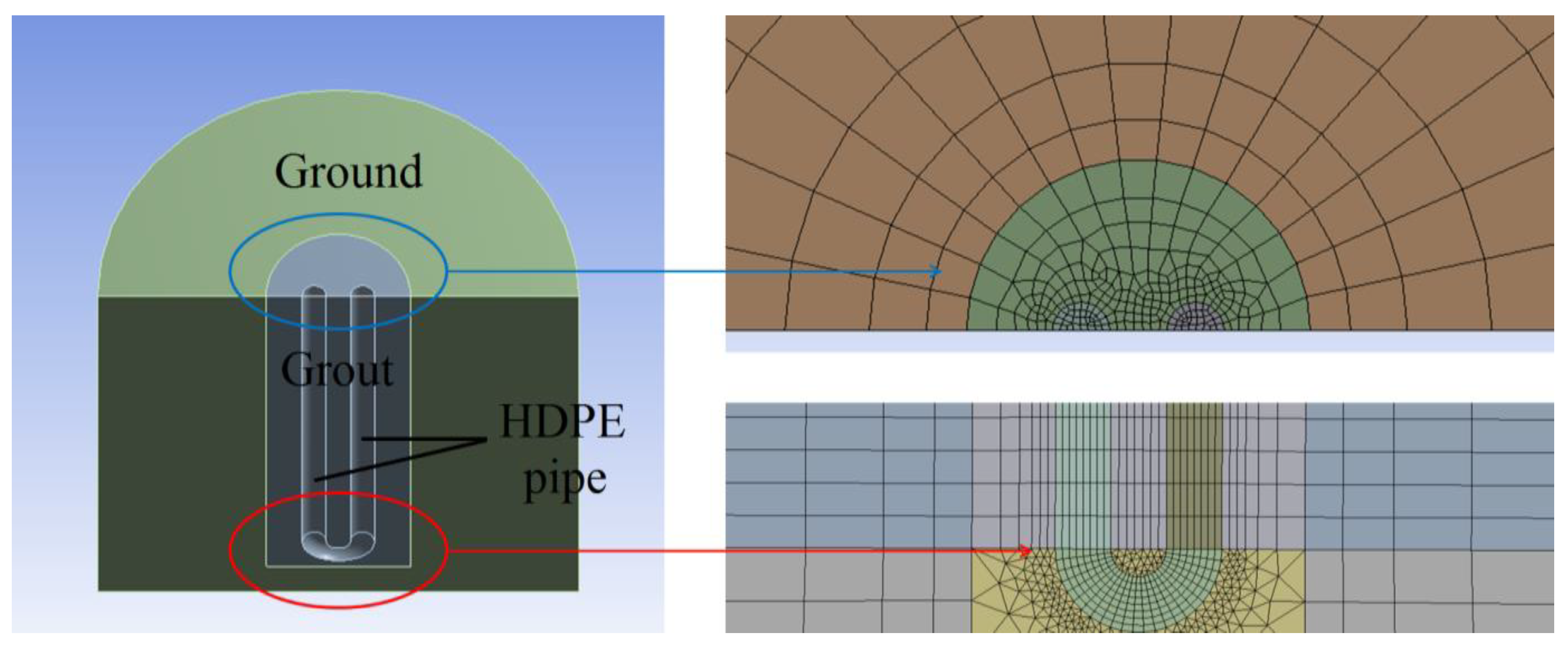
4.1. Numerical Method

We used commercial FLUENT CFD software to simulate a 3D vertical GHE [34]. Figure 5 shows the configuration and mesh of the model, which is made up of an HDPE pipe, grout, and the ground. In the model, the length, diameter, and thickness of the HDPE pipe are 50 m, 0.025 m, and 0.005 m; the depth and diameter of the borehole are 50.3 m and 0.15 m; and the depth and diameter of the ground are 51 m and 3 m, respectively. The thermal and physical properties of the bentonite-based grouts derived above were used in modeling (Table 3). The properties of the working fluid, the HDPE pipe, and the ground; and the boundary conditions; are listed in Table 4. Additional boundary conditions used in each section of the numerical analysis were as follows:
-
To investigate the effects of the SHC of bentonite-based grouts, HDPE pipe length, and working fluid velocity, the model simulated the cooling mode during intermittent operation (3 h operation time and 3 h off-time) and during continuous 24-h operation.
-
To investigate the effects of the operation time and off-time on vertical GHE, the model simulated the cooling mode during intermittent operation (3 h operation time and 3 h off-time) over three days.
-
To simulate the intermittent operation mode, user-defined operation times and off-times were modeled.
-
When exploring the effects of HDPE pipe length and working fluid velocity, and operation time and off-time, numerical simulations were performed using the thermal properties of the most diverse grout specimens (i.e., BS20-0, which has the lowest TC and the highest SHC, and BS30-30, which has the highest TC and the lowest SHC).
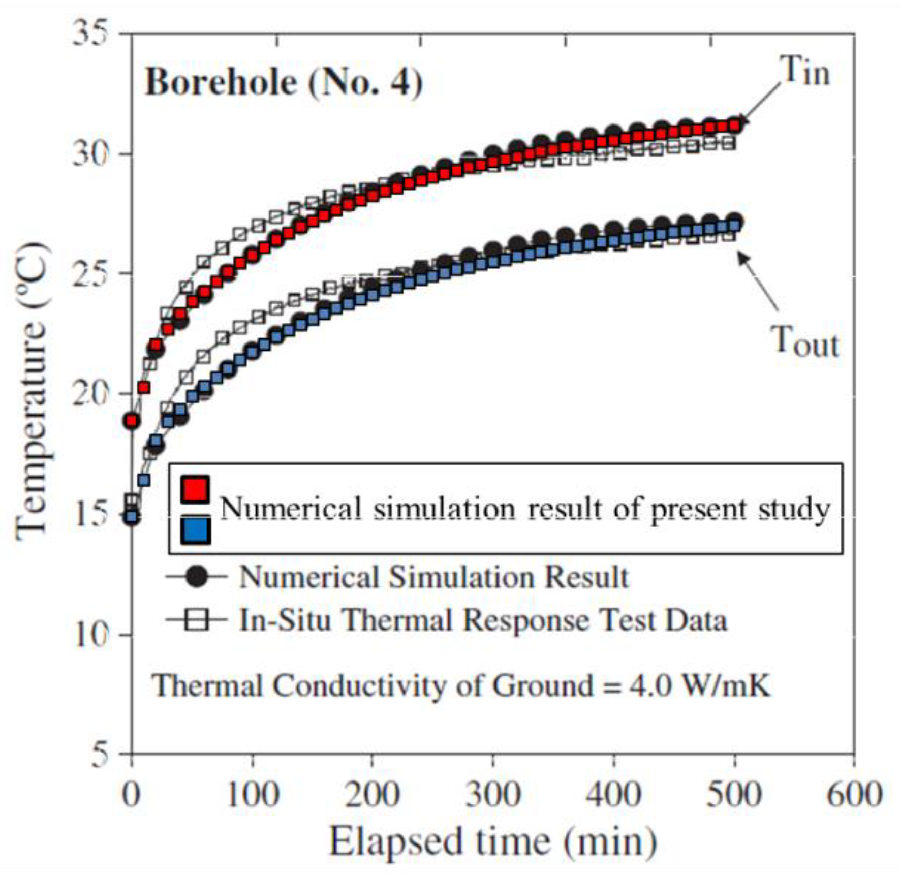
We considered the mass, momentum, and turbulence of the working fluid; and energy conservation by the grout and the ground. The SIMPLEC method, second-order upwind scheme, and realizable k-ε model were used [35]. The relevant equations are listed in Table 5.

4.2. Validation

We used the experimental data of Lee et al. [17] for verifying the accuracy of the 3D GHE model under the same conditions of the cited work. Lee et al. performed in situ TRT in Wonju, South Korea, and simulated the results. To simulate in situ TRT using bentonite-based grouts, we applied two user-defined functions accounting for variation in the ground temperature with depth (i.e., the geothermal gradient) and the difference in temperature between the working fluid inflow and outflow. Figure 6 compares the numerical simulations of the present study to the in situ TRT data and the numerical simulations of Lee et al. Overall, the results are in good agreement. Therefore, it can be concluded that our numerical model well predicts the heat transfer characteristics.

4.3. Numerical Results and Discussion

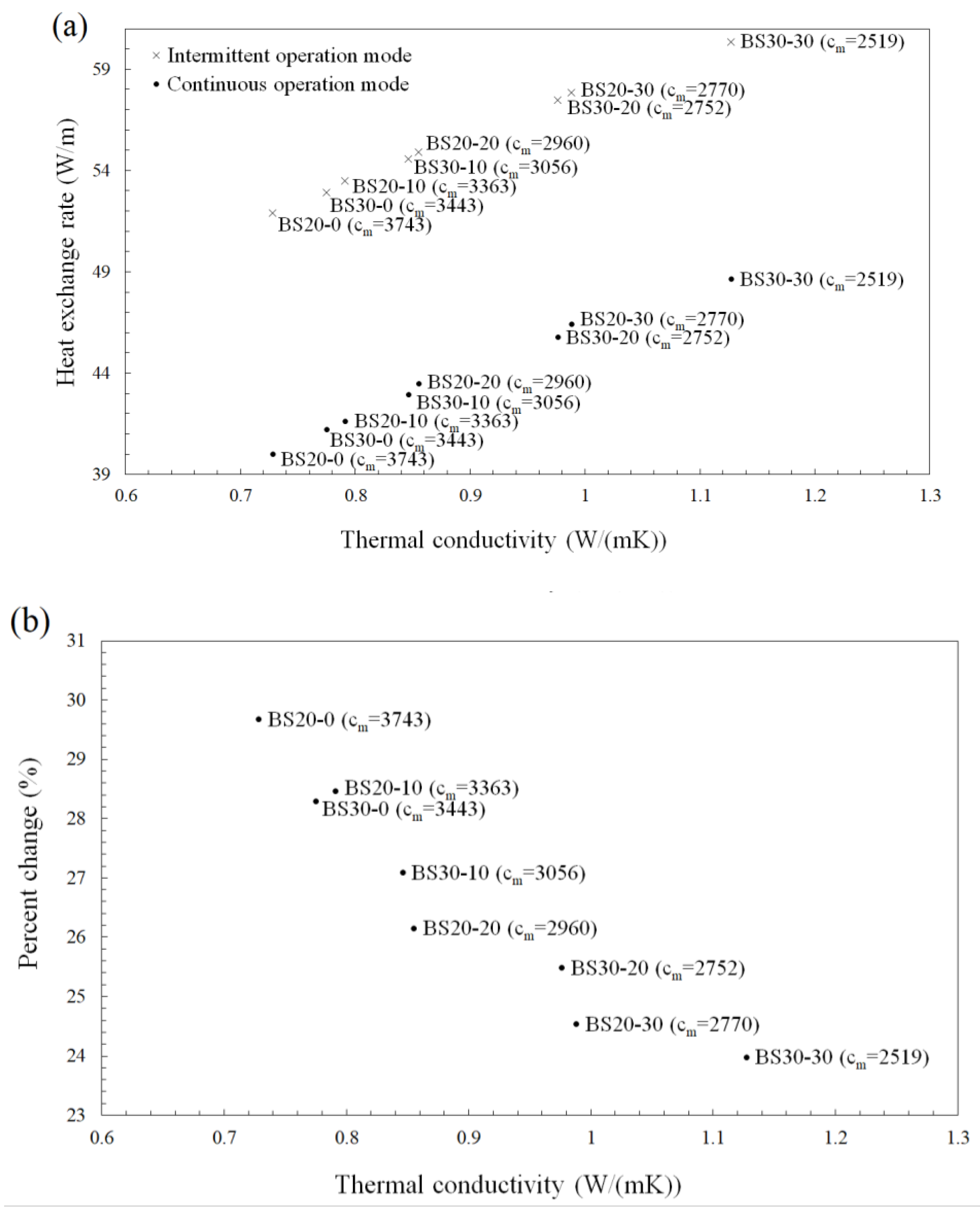
4.3.1. Effects of the Specific Heat Capacity of Bentonite-Based Grouts

When investigating the performance of a vertical GHE, we used the heat exchange rate (HER, W/m), calculated as:
HER = c m × m ˙   ( T i n T o u t ) l ,
where c m (J/(kgK)) is the SHC of the fluid, m ˙ (kg/s) the mass flow rate of the fluid, T i n (°C) the inlet temperature of the fluid, T o u t (°C) the outlet temperature of the fluid, and l (m) the length of the HDPE pipe.
The HERs for each specimen operating in the different modes are plotted in Figure 7a. In the continuous and intermittent modes, the higher the TC, the greater the HER. Moreover, the HERs during intermittent operation were higher than during continuous operation, reflecting ground temperature recovery during the off period. Therefore, use of the intermittent operation mode improved vertical GHE performance.
To investigate the effect of the SHC of grout, the percentage change in the HERs of the continuous and intermittent operation modes was calculated as:
Percent   change = HER int HER con HER con × 100 ( % ) ,
where HER int (%) and HER con (%) are the HERs during intermittent and continuous operation, respectively. The percentage changes in the HER under different operation modes are shown in Figure 7b. Overall, the higher the grout-SHC, the greater the change; the mean value for bentonite-based grout was 27%. These results are similar to those of a previous study on the effects of the SHC of cement-based grouts with silica sand as an additive [23]. However, as the numerical simulations were performed under the same conditions as applied in a previous study [23], the mean percentage changes associated with bentonite-based grouts were about 3% higher than those associated with cement-based grouts. To further investigate these effects during intermittent operation, we performed a numerical simulation using the highest TC and SHC of bentonite-based grouts measured in the present study. Then, the HER was 62.72 W/m, 2.39 W/m higher than that of BS30-30, which exhibited the same TC but the lowest SHC. Thus, during intermittent operation, use of a grout with a high SHC improves the vertical GHE performance; a bentonite-based grout would be preferred to a cement-based grout. However, when silica sand is used as an additive, the SHC of bentonite-based grout decreases as the amount of silica sand increases. Therefore, to develop a grout with not only high TC but also high SHC, improving vertical GHE performance, various other additives should be investigated and experimental studies conducted. Especially as an increase in the proportion of additive decreases the SHC, an additive affording high-level TC is required, even at small proportions.

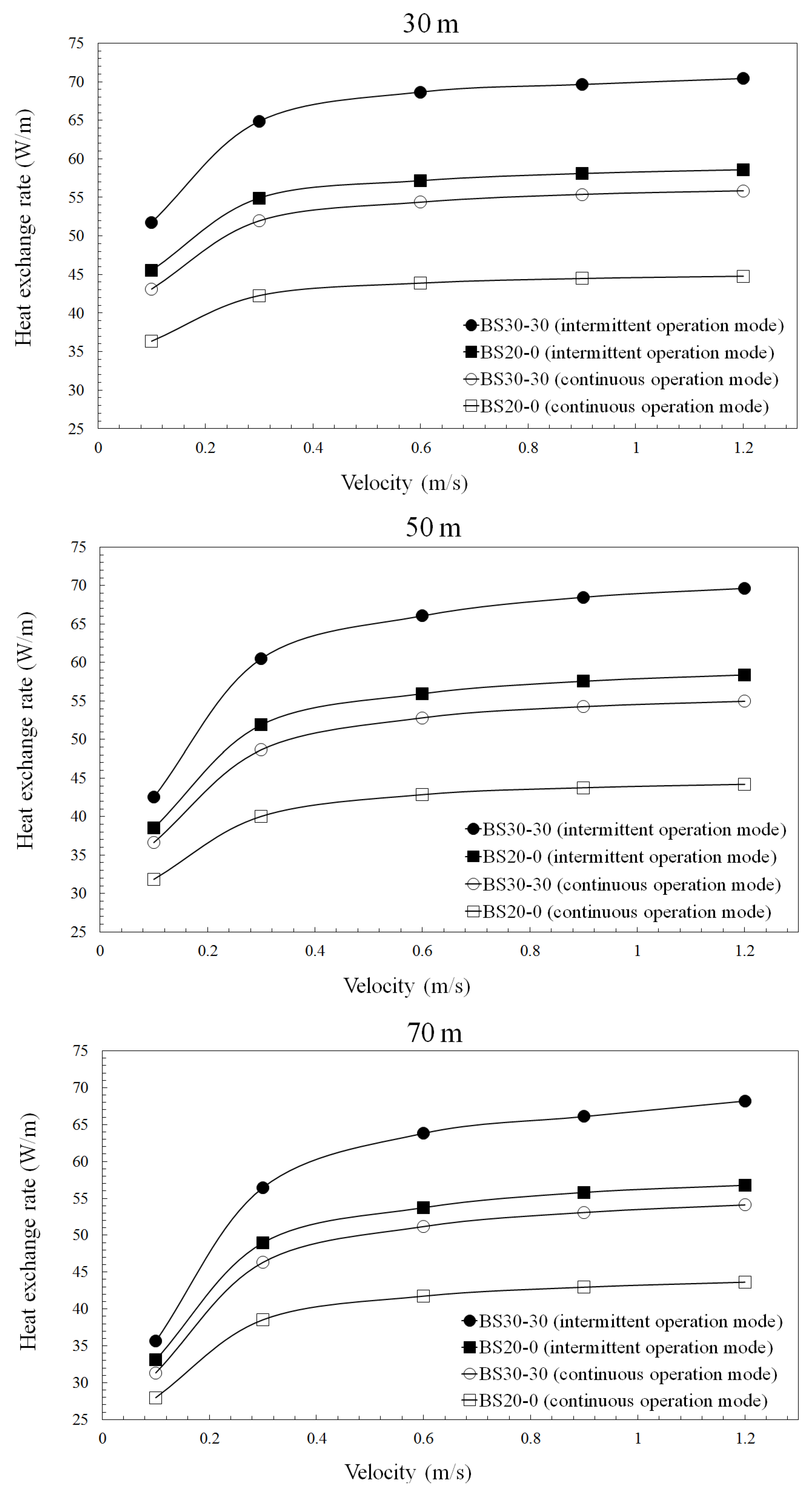
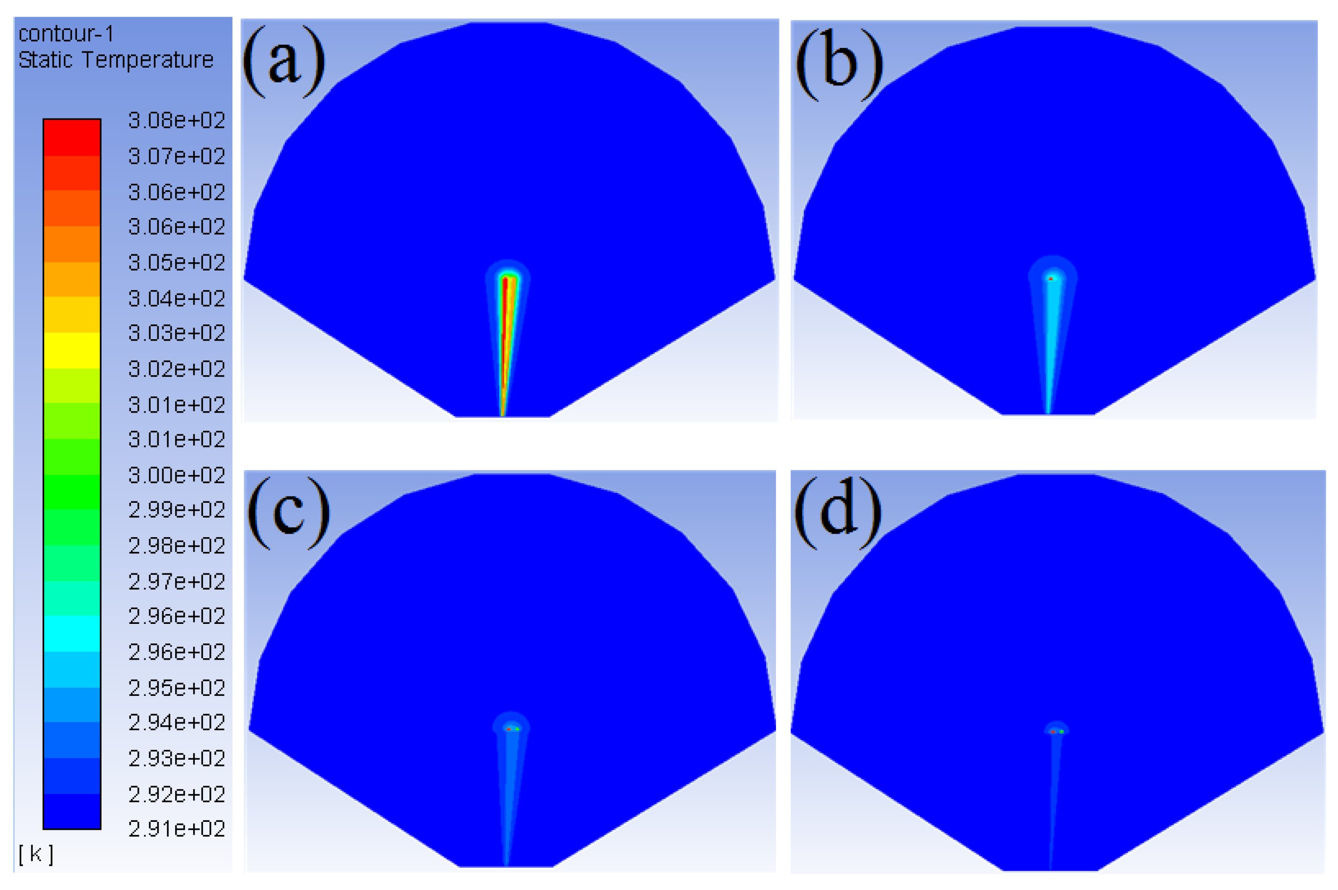
4.3.2. Effects of Working Fluid Velocity and HDPE Pipe Length

Figure 8 shows the changes in the HERs of BS20-0 and BS30-30 during continuous and intermittent operation at various fluid working velocities and HDPE pipe lengths. Overall, regardless of the pipe length, the HERs were higher during intermittent than continuous operation, and the HERs of BS30-30 (with a higher TC) were greater than those of BS20-0. In addition, the HERs increased as the working fluid velocity increased, similar to what was noted in a previous study [25]. However, when the working fluid velocity was <0.3 m/s, the HERs increased markedly, but when the velocity exceeded 0.3 m/s, the changes were small. This result indicates that there is a critical velocity for the working fluid that has a large effect on the performance of a vertical GHE, regardless of the operation mode, HDPE pipe’s length, and thermal properties of the grout; that flow rate is 0.3 m/s. Nevertheless, when the velocity was >0.3 m/s, the HERs increased slightly as the length of the HDPE pipe increased, but little difference in the HERs was evident at a velocity of 1.2 m/s. For example, during intermittent operation, the HER of BS30-30 was about 70 W/m at a fluid velocity of 1.2 m/s, regardless of HDPE pipe length, whereas the HERs at a fluid velocity of 0.3 m/s were 64.9 W/m, 60.5 W/m, and 56.5 W/m when the pipe length was 30 m, 50 m, and 70 m, respectively. This result indicates that there are optimum velocities for the working fluid depending on the length of the HDPE pipe (i.e., velocities in the range 0.3 to 1.2 m/s). Moreover, as shown in Figure 8, given the increase in HERs with increased HDPE pipe length and working fluid velocity, the optimum velocity for the working fluid is expected to increase as the length of the HDPE pipe increases. However, since increasing the velocity of the working fluid can increase energy consumption, additional field studies should be carried out to determine the optimum velocity for a vertical GHE for a given length of HDPE pipe.

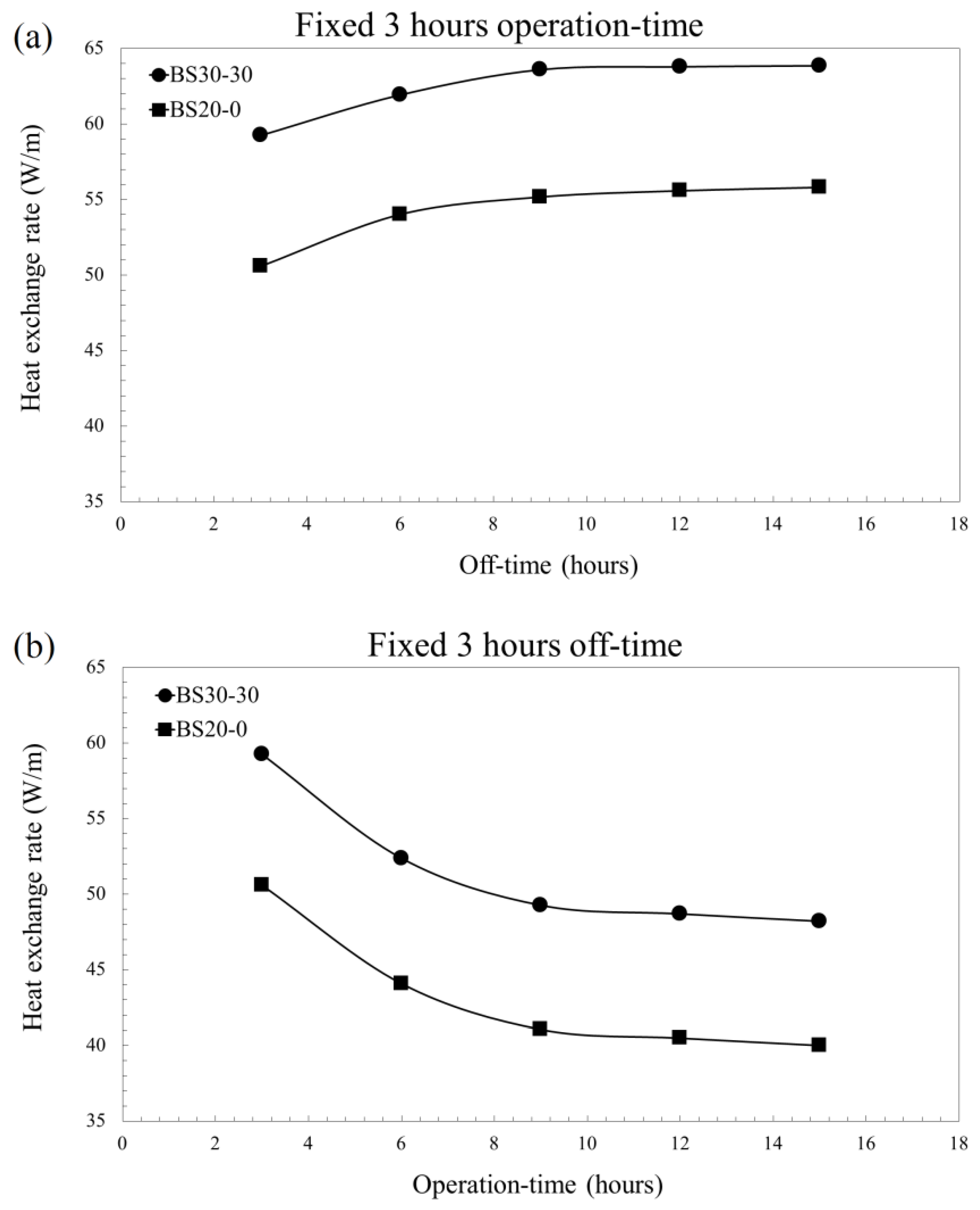
4.3.3. Effects of Various Operation Times and Off-Times during Intermittent Operation

Figure 9a shows the changes in HERs of BS20-0 and BS30-30 grouts during intermittent operation over three days, when the operation time was 3 h and the off-time varied. Figure 9b shows the changes in HERs of BS20-0 and BS30-30 grouts during intermittent operation over three days, when the off-time was fixed at 3 h and the operation time varied. Overall, the higher the grout TC, the higher the HER; as the operation time or off-time increased, the HERs were similar regardless of the thermal properties of the grout. However, as shown in Figure 9a, when the off-time exceeded 9 h, the HERs differed only marginally, attributable to recovery of the ground temperature during the long off-time. In Figure 10, which is the simulation for BS20-0, panel (a) shows the ground temperature distribution when the operation time is 3 h and panels (b), (c), and (d) show the ground temperature distributions after 3 h of operation at off-times of 3, 6, and 9 h, respectively. The ground temperature recovered gradually as off-time increased; after 9 h, the ground temperature had almost completely recovered. This identifies a critical time when the temperature of the ground has become almost completely restored; this time depends on the operation time and off-time, not on the thermal properties of the grout. Also, as shown in Figure 9b, when the operation time exceeded 9 h, little change in the HERs was evident, probably because the ground temperature had not recovered sufficiently during the off-time given the long operation time. The HERs of BS20-0 and BS30-30 during continuous operation over three days were 37.86 W/m and 46.49 W/m, respectively, similar to those associated with operation times ≥9 h (Figure 9b). This indicates that there is a critical interval at which any beneficial effect of intermittent operation almost disappears if the operation time is too long, regardless of the thermal properties of the grout. Therefore, after installation of a vertical GHE, it may be possible to use our method to estimate the critical times for optimizing intermittent operation. Using our present results as an example, if the operation time is 3 h, it is not necessary to set the off-time to ≥9 h, because the ground temperature recovers almost completely. Also, if the off-time is 3 h, the operation time should be set to <9 h; otherwise, the beneficial effect of intermittent operation almost disappears. Therefore, if the optimal operation time and off-time are thus determined, the vertical GHE will operate more efficiently. However, the critical times (when the ground temperature is almost completely restored and the benefit of intermittent operation almost disappears) may depend on the working fluid velocity, borehole depth, ground thermal properties, and operation time and off-time. Therefore, to efficiently apply our method, additional field investigations are required.

5. Conclusions

We studied the thermal properties of bentonite-based grouts used to construct vertical GHEs and explored the effects on GHE performance of grout-SHC, HDPE pipe length, working fluid velocity, and operation time and off-time during intermittent operation. We also performed numerical simulations using the measured thermal properties.
(1)
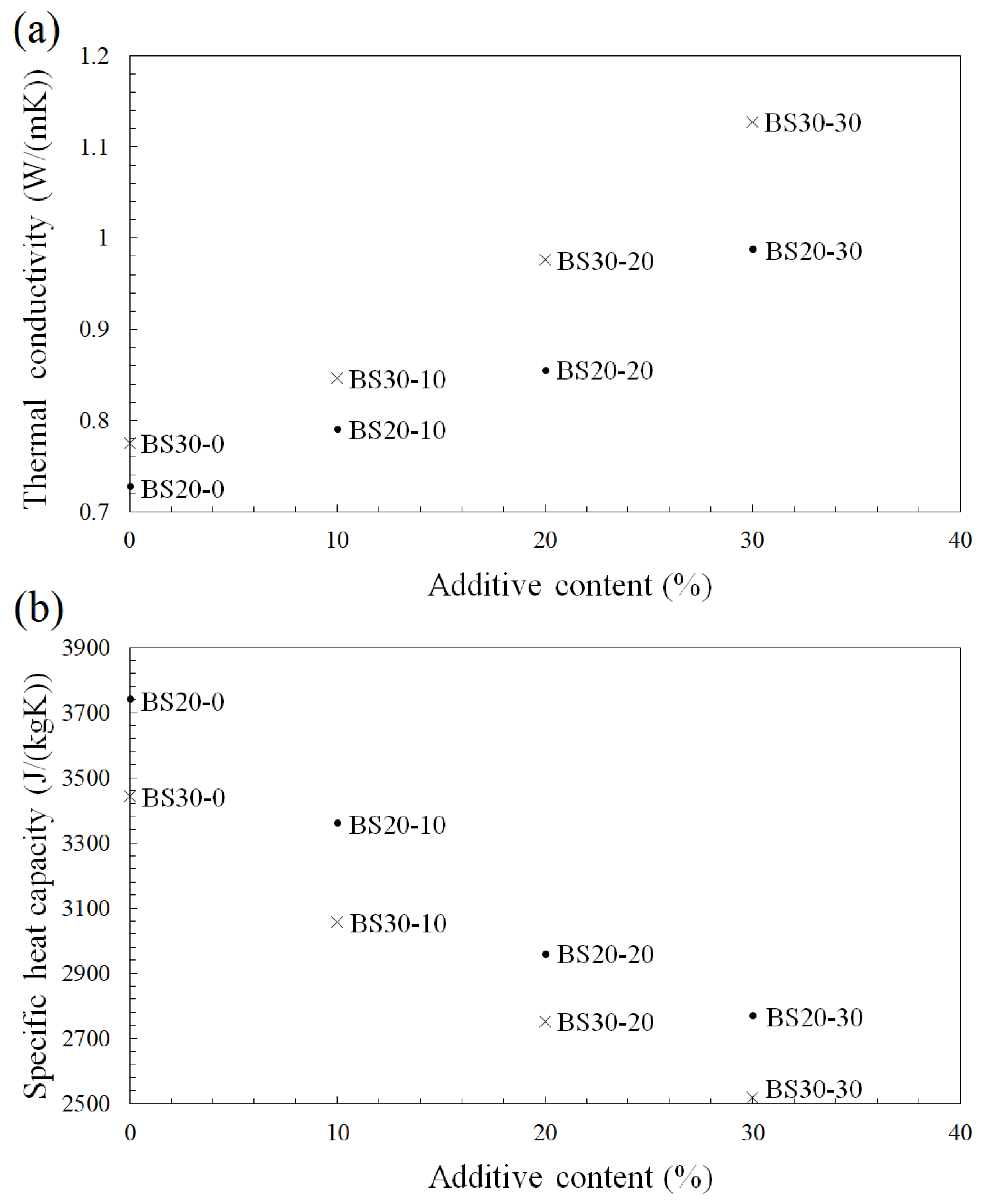
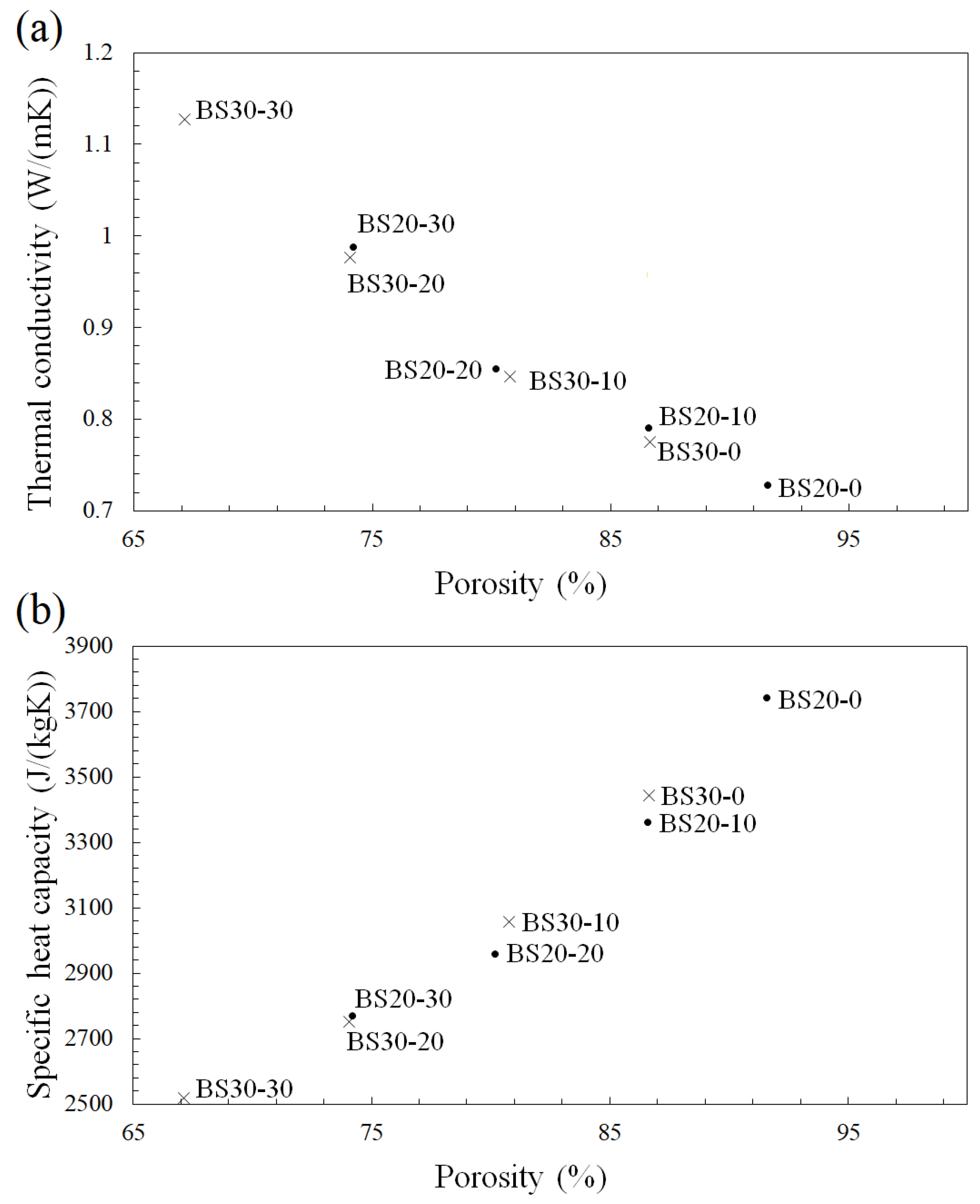
Under saturated conditions, the TC and SHC of bentonite-based grouts ranged from 0.728–1.127 W/(mK) and 2519–3743 J/(kgK), respectively. As the proportion of silica sand increased, the TC of the bentonite-based grouts increased, but the SHC decreased. The thermal properties of bentonite-based grouts were affected principally by composition and porosity.
(2)
For bentonite-based grouts, the mean HER was 27% higher during intermittent operation than during continuous operation. Also, during intermittent operation, grout with high TC and high SHC improved GHE performance. Because the SHC of bentonite-based grout is higher than that of cement-based grout, the effect of bentonite-based grout was more significant.
(3)
During both continuous and intermittent operation, GHE performance improved as the working fluid velocity increased. However, there was a critical working fluid velocity that greatly affected the performance of the vertical GHE, regardless of the operation mode, HDPE pipe length, or grout thermal properties; this value was 0.3 m/s. Therefore, it is recommended to set the velocity for operation of the vertical GHE to 0.3 m/s or higher.
(4)
During intermittent operation, depending on the operation time and off-time, we found critical time intervals at which the ground temperature was almost completely restored, or any benefit of intermittent operation almost disappeared. Moreover, the method to estimate the critical time intervals for optimizing intermittent operation was proposed. Our results can be used as input data for analyses of the thermal behavior of vertical GHEs to improve GHE performance and operation.

Author Contributions

D.K. and S.O. conceived the study plan and contributed to the analysis and to the experiment. All authors read and approved the final manuscript.

Funding

This research was supported by the National Strategic Project-Carbon Upcycling of the National Research Foundation of Korea (NRF) funded by the Ministry of Science and ICT (MSIT), the Ministry of Environment (ME) and the Ministry of Trade, Industry and Energy (MOTIE) (NRF-2017M3D8A2085342).

Conflicts of Interest

The authors declare no conflict of interest.

References

  1. Blazquez, C.S.; Martin, A.F.; Nieto, I.M.; Garcia, P.C.; Sanchez Perez, L.S.; Gonzalez-Aguilera, D. Analysis and study of different grouting materials in vertical geothermal closed-loop systems. Renew. Energy 2017, 114, 1189–1200. [Google Scholar] [CrossRef]
  2. Wang, H.; Lu, J.; Qi, C. Thermal conductivity of sand bentonite mixtures as a backfill material of geothermal boreholes. GRC Trans. 2011, 35, 1135–1138. [Google Scholar]
  3. Indacoechea-Vega, I.; Pascual-Muñoz, P.; Castro-Fresno, D.; Calzada-Pérez, M.A. Experimental characterization and performance evaluation of geothermal grouting materials subjected to heating-cooling cycles. Constr. Build. Mater. 2015, 98, 583–592. [Google Scholar] [CrossRef]
  4. Lund, J.W.; Boyd, T.L. Direct utilization of geothermal energy 2015 worldwide review. Geothermics 2016, 60, 66–93. [Google Scholar] [CrossRef]
  5. Yang, H.; Cui, P.; Fang, Z. Vertical-borehole ground-coupled heat pumps: A review of models and systems. Appl. Energy 2010, 87, 16–27. [Google Scholar] [CrossRef]
  6. Cui, P.; Yang, H.; Fang, Z. Numerical analysis and experimental validation of heat transfer in ground heat exchangers in alternative operation modes. Energy Build. 2008, 40, 1060–1066. [Google Scholar] [CrossRef]
  7. Lee, J.Y. Current status of ground source heat pumps in Korea. Renew. Sustain. Energy Rev. 2009, 13, 1560–1568. [Google Scholar] [CrossRef]
  8. Hu, J. An improved analytical model for vertical borehole ground heat exchanger with multiple-layer substrates and groundwater flow. Appl. Energy 2017, 202, 537–549. [Google Scholar]
  9. Chong, C.S.A.; Gan, G.; Verhoef, A.; Garcia, R.G. Comparing the thermal performance of horizontal slinky-loop and vertical slinky-loop heat exchangers. Int. J. Low-Carbon Technol. 2014, 9, 250–255. [Google Scholar] [CrossRef]
  10. Choi, W.; Ooka, R. Effect of natural convection on thermal response test conducted in saturated porous formation: Comparison of gravel-backfilled and cement-grouted borehole heat exchangers. Renew. Energy 2016, 96, 891–903. [Google Scholar] [CrossRef]
  11. Desmedt, J.; Van Bael, J.; Hoes, H.; Robeyn, N. Experimental performance of borehole heat exchangers and grouting materials for ground source heat pumps. Int. J. Energy Res. 2012, 36, 1238–1246. [Google Scholar] [CrossRef]
  12. Remund, C.P.; Lund, J.T. Thermal Enhancement of Bentonite Grouts for Vertical GSHP Systems in Heat Pump and Refrigeration Systems; Den Braven, K.R., Mei, V., Eds.; American Society of Mechanical Engineers: New York, NY, USA, 1993; Volume 29, pp. 95–106. [Google Scholar]
  13. Lee, C.H.; Lee, K.J.; Choi, H.S.; Choi, H.P. Characteristics of thermally-enhanced bentonite grouts for geothermal heat exchanger in South Korea. China Technol. Sci. 2011, 53, 123–128. [Google Scholar] [CrossRef]
  14. Allan, M.L.; Philippacopoulos, A.J. Properties and Performance of Thermally Conductive Cement-Based Grouts for Geothermal Heat Pumps; Department of Applied Science, Brookhaven National Laboratory: New York, NY, USA, 1999. [Google Scholar]
  15. Lee, C.H.; Park, M.S.; Nguyen, T.B.; Sohn, B.H.; Choi, H.S. Performance evaluation of closed-loop vertical ground heat exchangers by conducting in-situ thermal response tests. Renew. Energy 2012, 42, 77–83. [Google Scholar] [CrossRef]
  16. Esen, H.; Inalli, M.; Esen, Y. Temperature distributions in boreholes of a vertical ground-coupled heat pump system. Renew. Energy 2009, 34, 2672–2679. [Google Scholar] [CrossRef]
  17. Lee, C.; Park, M.; Park, S.; Won, J.; Choi, H. Back-analyses of in-situ thermal response test (TRT) for evaluating ground thermal conductivity. Int. J. Energy Res. 2013, 37, 1397–1404. [Google Scholar] [CrossRef]
  18. Jalaluddin; Miyara, A. Thermal performance investigation of several types of vertical ground heat exchangers with different operation mode. Appl. Therm. Eng. 2012, 33, 167–174. [Google Scholar] [CrossRef] [Green Version]
  19. Choi, J.C.; Lee, S.R.; Lee, D.S. Numerical simulation of vertical ground heat exchangers: Intermittent operation in unsaturated soil conditions. Comput. Geotech. 2011, 38, 949–958. [Google Scholar] [CrossRef]
  20. Li, Y.; An, Q.S.; Liu, L.X.; Zhao, J. Thermal performance investigation of borehole heat exchanger with different U-tube diameter and borehole parameters. Energy Procedia 2014, 61, 2690–2694. [Google Scholar] [CrossRef]
  21. Bidarmaghz, A.; Narsilio, G.A.; Johnston, I.W.; Colls, S. The importance of surface air temperature fluctuations on long-term performance of vertical ground heat exchangers. Geomech. Energy Environ. 2016, 6, 35–44. [Google Scholar] [CrossRef]
  22. Congedo, P.M.; Colangelo, G.; Starace, G. CFD simulations of horizontal ground heat exchangers: A comparison among different configurations. Appl. Therm. Eng. 2012, 33–34, 24–32. [Google Scholar] [CrossRef]
  23. Kim, D.; Kim, G.; Kim, D.; Baek, H. Experimental and numerical investigation of thermal properties of cement-based grouts used for vertical ground heat exchanger. Renew. Energy 2017, 112, 260–267. [Google Scholar] [CrossRef]
  24. Pu, L.; Qi, D.; Li, K.; Tan, H.; Li, Y. Simulation study on the thermal performance of vertical U-tube heat exchangers for ground source heat pump system. Appl. Therm. Eng. 2015, 79, 202–213. [Google Scholar] [CrossRef]
  25. Chen, S.; Mao, J.; Han, X.; Li, C.; Liu, L. Numerical analysis of the factors influencing a vertical u-tube ground heat exchanger. Sustainability 2016, 8, 882. [Google Scholar] [CrossRef]
  26. Chen, J.; Xia, L.; Li, B.; Mmereki, D. Simulation and experimental analysis of optimal buried depth of the vertical U-tube ground heat exchanger for a ground-coupled heat pump system. Renew. Energy 2015, 73, 46–54. [Google Scholar] [CrossRef]
  27. Jin, G.; Zhang, X.; Guo, S.; Wu, X.; Bi, W. Evaluation and analysis of thermal short-circuiting in borehole heat exchangers. In Proceedings of the 8th International Conference on Applied Energy (ICAE2016), Beijing, China, 8–11 October 2016; pp. 1677–1682. [Google Scholar]
  28. Welch, S.M.; Kluitenberg, G.J.; Bristow, K.L. Rapid numerical estimation of soil thermal properties for a broad class of heat-pulse emitter geometries. Meas. Sci. Technol. 1996, 7, 932–938. [Google Scholar]
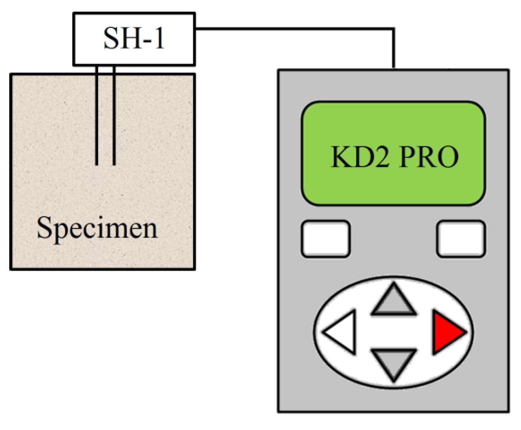
  29. Bristow, K.L. Measurement of thermal properties and water content of unsaturated sandy soil using dual-probe heat-pulse probes. Agric. Forest Meteorol. 1998, 89, 75–84. [Google Scholar] [CrossRef]
  30. KD2 Pro Manual. Available online: http://manuals.decagon.com/Manuals/13351_KD2%20Pro_Web.pdf (accessed on 20 July 2018).
  31. Cengel, Y.A. Heat and Mass Transfer: A Practical Approach; McGraw-Hill: New York, NY, USA, 2006. [Google Scholar]
  32. Hens, H. Applied Building Physics: Boundary Conditions, Building Performance and Material Properties; Wiley: Berlin, Germany, 2010. [Google Scholar]
  33. Engineeringtoolbox. Available online: http://www.engineeringtoolbox.com/specific-heat-capacity-d_391.html (accessed on 20 July 2018).
  34. Fluent 6.3 User’s Guide. Available online: https://www.sharcnet.ca/Software/Fluent6/html/ug/main_pre.htm (accessed on 20 July 2018).
  35. Gao, J.; Zhang, X.; Liu, J.; Li, K.S.; Yang, J. Numerical and experimental assessment of thermal performance of vertical energy piles: An application. Appl. Energy 2008, 85, 901–910. [Google Scholar] [CrossRef]
Figure 1. The grain size distribution curve of the silica sand.
Sustainability 10 02664 g001
Figure 2. Schematic of the thermal property measurement setup.
Sustainability 10 02664 g002
Figure 3. (a) Thermal conductivity and (b) specific heat capacity of specimens with various proportions of additives.
Sustainability 10 02664 g003
Figure 4. The relationships between porosity and thermal properties. (a) Thermal conductivity vs. porosity; (b) Specific heat capacity vs. porosity.
Sustainability 10 02664 g004
Figure 5. The configuration and mesh of the 3D vertical ground heat exchanger (GHE).
Sustainability 10 02664 g005
Figure 6. Numerical simulation of the present study, the in situ thermal response testing (TRT) data, and the numerical simulation of Lee et al. [17].
Sustainability 10 02664 g006
Figure 7. (a) Mean heat exchange rates in different operation modes; (b) Percentage changes in heat exchange rates between different operation modes ( c m (J/(kgK)): the specific heat capacity of each specimen).
Sustainability 10 02664 g007
Figure 8. The effects of working fluid velocity and high-density polyethylene (HDPE) pipe length in different operation modes.
Sustainability 10 02664 g008
Figure 9. (a) Heat exchange rates by off-time; (b) Heat exchange rates by operation time.
Sustainability 10 02664 g009
Figure 10. (a) Ground temperature distribution 3 h after operation; (b) Ground temperature distribution after 3 h of off-time; (c) Ground temperature distribution after 6 h of off-time; (d) Ground temperature distribution after 9 h of off-time.
Sustainability 10 02664 g010
Table 1. Physical properties of Volclay bentonite.
Permeability (cm/s)Swelling PotentialMontmorillonite Content (%)Thermal Conductivity (W/(mK))Specific Gravity
≤1 × 10−725 mL/2.0 g≤900.742.60
Table 2. Mix proportions for test specimens.
Specimen No.Bentonite (wt %)Silica Sand (wt %)Water (wt %)
BS20-020080
BS20-101070
BS20-202060
BS20-303050
BS30-030070
BS30-101060
BS30-202050
BS30-303040
wt: weight percentage.
Table 3. Physical and thermal properties of all specimens.
Specimen No.Saturated Bulk Density (kg/m3)Porosity (%)Thermal Conductivity (W/(mK))Specific Heat Capacity (J/(kgK))
BS20-0109691.570.7283743
BS20-10117086.560.7913363
BS20-20129880.170.8552960
BS20-30135474.190.9882770
BS30-0115886.640.7753443
BS30-10125680.780.8463056
BS30-20135974.060.9762752
BS30-30143967.111.1272519
Table 4. Parameters for simulation analysis [17,23].
ItemDescription
Inlet water velocity0.3 m/s
Inlet water temperature35 °C (308.15 K)
Turbulence intensity5%
Initial ground temperature18.2 °C (291.35 K)
Physical ParametersDensity (kg/m3)Thermal Conductivity (W/(mK))Specific Heat Capacity
(J/(kgK))
Viscosity
(kg/(ms))
Working fluid998.20.641820.001003
HDPE pipe9550.4525
Ground26004.0790
HDPE, high-density polyethylene.
Table 5. Summary of CFD model equations [34].
Continuity equation ρ t + ( ρ v   ) = 0
Momentum equation ρ v t + ( ρ v × v   ) ( μ e f f   v ) = p + ( μ e f f v ) T + S
Energy equation ( ρ h ) t ( p ) t + ( ρ v h   ) = [ ( μ + μ t σ t ) h ] S h
Turbulence equationsTurbulent energy equation ( ρ k ) t + ( ρ v k   ) = [ ( μ + μ t σ k ) k ] + G k + G b ρ ε
Turbulence dissipation rate equation ( ρ ε ) t + ( ρ v ε ) = [ ( μ + μ t σ ε ) ε ] + ε λ ( c ε 1 G k c ε 2 ρ ε )
c ε 1 : 1.44, c ε 2 : 1.92 ε : turbulent dissipation rate (m2/s2)
G b , G k : turbulence kinetic energies (m2/s2) μ : viscosity ((Ns)/m2)
h : enthalpy of the fluid (J) μ e f f : effective viscosity ((Ns)/m2)
k : turbulence kinetic energy (m2/s2) μ t : turbulence viscosity ((Ns)/m2)
p : pressure (Pa) v : velocity (m/s)
S : source term ρ : density (kg/m3)
S h : volumetric heat source (kJ/(m3s)) σ ε : 1.2, σ k :   1 , σ t : constant
t : time (h)
T : Temperature (°C)

