Abstract
Residential and commercial buildings consume nearly 40 percent of total USA energy use and account for one-third of total greenhouse gas emissions. The challenges are how to effectively promote energy efficiency in buildings to respond to the high financial burden of energy consumption, while reducing pollution. Phase change materials (PCMs) have been used as passive energy storage for building systems. Along this vein, this study aims to numerically elucidate the design parameters of building envelopes strengthened by PCM layers, and unveil their impacts on building energy efficiency. Critical design variables, such as the thickness of the PCM layer, the latent heat of PCMs, or melting temperature of PCMs were selected for a parametric study, while performance metrics were used to assess building efficiency. Results revealed that PCM-enabled building walls exhibited different levels of improvement, in terms of reduction of peak temperature and temperature swings. Among the variables, the selection of the proper melting point for a PCM was identified as the most crucial parameter for determining building energy efficiency, while the heat of fusion was also observed as a critical property of PCM for building potential. Findings also demonstrated that the placement of the PCM near the interior wall surface could achieve higher efficiency, as compared to other cases. Results also showed that the thermal conductivity of PCM has a minimum contribution to energy storage capacity.
1. Introduction
Promotion of energy efficiency in the building sector is a pressing need in order to respond to the high financial burden of energy consumption. A recent energy consumption survey by the United States Energy Information Administration clearly reveals that residential and commercial buildings consume over 38 quadrillion BTUs (energy unit), about 39% of total USA energy use in 2017. Over the past decades, the development of advanced engineered materials and the improvement in design specifications [1,2,3] have spurred tremendous progress in energy-efficient building envelopes (e.g., walls, roofs, and foundation) to reduce space heating and cooling loads. Among them, phase change materials (PCMs), due to their superior latent heat energy storage capacity, have been gaining much interest in applications to building envelopes in recent years [4,5,6]. For instance, literature reviews [7,8] show that wall assemblies reinforced by PCM layers offer improved thermal comfort for indoor environments in terms of reducing temperature fluctuation, and cut significant cost through shifting the cooling load to off-peak electricity load.
Significant efforts [9] have been made in the implementation of PCMs in building envelopes through either experimental, analytical or numerical studies. Lei et al. [10] simulated building envelopes integrated with a PCM layer using software EnergyPlus® (National Renewable Energy Laboratory, 15013 Denver West Parkway Golden, CO 80401, USA) and evaluated the energy performance of the building system for cooling load reduction in tropical Singapore. Their results showed that PCM can effectively reduce heat gains through building envelopes throughout the whole year, indicating the significant advantage of using PCMs in the buildings located in hot circumstances. Seong and Lim [11] investigated the energy saving potentials in buildings with PCMs in a lightweight building envelope, and found both the peak heating load and highest indoor temperature decreased when various PCMs with different phase change temperatures were applied. Wang et al. [12] experimentally evaluated the year-round applicability of an exterior wall with PCM-bricks and found a reduction of 0.2 °C for the maximum interior wall surface temperature and a time delay of about 1–2 h under summer seasons. Izquierdo-Barrientos et al. [13] studied the performance of external building wall assemblies containing a PCM layer. They concluded that the influencing factors included the orientation of the wall, the position of the PCM layer, and the phase change temperature. Jin et al. [14] numerically analyzed the effects of the location of a thin PCM layer placed in frame walls. They stated that the optimal locations of the PCM layer should be near to the exterior surface of the wall, if using thicker PCM layers, the higher the heat of fusion, and the higher the melting temperature. Different to the observation by Jin et al. [14], Zwanzig et al. [15] found that that the centrally located PCM composite wall board performed better under both the heating and cooling seasons, as compared to either externally or internally located PCM walls. In general, these studies [12] have demonstrated the improvement of energy efficiency through the use of PCMs for a building environment. Due to different focuses in those previous studies, each individual investigation [13] may be conducted on the PCM-enabled buildings using one or two variables, such as the location of PCM or its melting temperature. Moreover, some conclusions may conflict with each other. For instance, there is still open questions about how to select melting temperature for a PCM layer and where the optimal location for a PCM layer is. Clearly, it necessitates comprehensive parametric studies, as proposed in this study, that could efficiently assist the building community and stakeholders, from builders, designers, building manufacturers, and to state/local governments, to identify better design.
Correspondingly, selection of proper performance metrics is another key piece of information required to evaluate the robustness of the design of building envelopes and elucidate critical factors affecting their energy efficiency. Reduction of peak temperature and temperature shifting hour are currently used through a comparison to determine the effectiveness of building envelopes with and without PCMs. Cabeza et al. [16] experimentally studied energy saving through using microencapsulated PCM in concrete walls, and found that air temperature in the room with PCM could lead to a reduction by up to 2 °C, as compared to conventional walls. Moreover, Kuznik and Virgone [17] introduced a decrement factor defined as the ratio between the amplitude of the indoor air temperature in the cell with and without PCM to evaluate their energy efficiency. Some argued that such performance metrics could only provide discrete/local information, while ignoring the temporal data representation over time and detailing of the PCMs’ impacts to building comfort. To improve performance metrics, Evola et al. [18,19] developed comprehensive assessment methods, including the evaluation of the intensity of thermal discomfort, frequency of thermal comfort, frequency of activation, and storage efficiency of the PCMs. Thus, as a key step, we will evaluate the existing performance metrics in determining the implementation techniques for PCMs and their installation patterns to minimize the energy demand of a building.
Therefore, the objectives of this study aim to numerically investigate the thermodynamics of PCM-enabled building envelopes. A comprehensive and systematic study is conducted on external wall assemblies reinforced by a PCM layer as a representative under summer weather and solar radiation. A parametric study focuses on identified critical variables, including the location and thickness of the PCM layer, the latent heat of PCMs, melting temperature of PCMs, and the thermal conductivity of PCMs. Four metrics, the temperature swings, the peak temperature reduction, intensity of thermal discomfort for overheating, and frequency of thermal comfort, are accordingly selected to assess building efficiency.
2. PCMs for Building Envelopes and Building Systems
Improving the energy efficiency of buildings is one of the major topics for energy saving at regional, national, and international levels. Introducing thermal energy storage systems (TESS) into building envelopes shows promising enhancement of the building energy performance [20]. Agyenim [21] listed the classification of energy storage, including in the form of sensible heat in a liquid or solid medium, as heat of fusion (latent heat), or as chemical energy or products in a reversible chemical reaction. To date, most of the researchers investigating TESS have focused on sensible and latent heat storage systems. Compared to sensible heat storage, latent heat storage implemented with the energy charge and discharge of PCM shows a significant reduction in storage volume. PCM such as calcium chloride hexahydrate can store/release 193 kJ/kg of heat on phase transition process, as compared to conventional building materials, such as concrete, having a sensible heat capacity of about 1.0 kJ/kg [22]. A further advantage of the latent heat storage is that the phase transition process often occurs over a narrow temperature range, resulting in a reduced temperature fluctuation in building applications. Phase change materials in the current market can be classified into organic compounds, inorganic compounds, and eutectic compounds. Paraffin wax included in organic PCMs is taken as suitable material for buildings due to its desirable properties including high latent heat of transition, long-term chemical stability, non-toxicity, favorable phase-transition temperature, no/little supercooling, and low cost [9].
Phase change materials have been embedded in building envelopes in different forms, such as encapsulation in fins or impregnation in porous materials, as detailed in the References [23,24,25,26,27,28,29,30], and then implemented into the building components (e.g., wallboards, concrete blocks, ceilings, and floors). As exterior temperature and solar radiation increase, the PCMs embedded in those components absorb a large amount of heat, change from solid to liquid, and meanwhile store the heat in the form of latent thermal energy. This whole process can be completed over a limited temperature range, and the PCMs act as an almost isothermal reservoir of heat [31]. When the temperature decreases, the thermal energy stored can be released automatically to heat the indoor air, with the PCMs changing from liquid to solid. During this process, these structure components provide adequate surface area to deliver heat to the building. In recent years, the use of PCMs in buildings with the aim of improving thermodynamic response and efficiency of building envelope has drawn more and more attention.
A literature review below is specified to identify the design variables and performance metrics of interest.
2.1. Critical Factors Affecting the Thermodynamics and Energy Efficiency of PCM-Enabled Building Envelopes
As stated early, the improvement in energy efficiency of PCM-enabled building envelopes has been observed by many researchers [32]. Izquierdo-Barrientos et al. [13] stated the importance of these variables: (a) the position of the PCM layer and (b) the phase change temperature. Jin et al. [14] and Zwanzig et al. [15] recognized the contribution of location of PCM layers the building energy efficiency. Jing [32] compared the energy saving performance of building envelopes with PCMs and traditional building materials and drew the conclusion that the energy-saving efficiency increased by 27.56% when PCM was integrated in the buildings. Kuznik et al. [33] studied the effect of PCM thickness on the thermal behavior of the building wall and provided an optimal PCM thickness value for the construction. Lee et al. [34] assessed the impact of the location of the PCM layer in a residential building wall on the heat transfer reduction of the wall, and found that the optimal location for a PCM layer is the middle part of the wall. Xu et al. [35] investigated several design variables, such as melting temperature and thermal conductivity of the PCM. It was found that for a given position or weather condition, the melting temperature of PCM should be selected to near the average indoor air temperature of sunny winter days, and the thermal conductivity should be larger than 0.5 W/(mK). Zhu et al. [36] explored the effect of melting temperature and corresponding thickness of the PCM-based wall in typical climate regions of China. Jayalath et al. [37] illustrated that the amount of PCM integrated in the building material, corresponding to different heat of fusion, also has an obvious effect on the thermodynamics of the wall. The maximum indoor temperature decreases with the increase of the heat of fusion.
To sum up, these factors, such as the location of the PCM layer, thickness of the PCM layer, the latent heat of PCM, melting temperature of PCM, and thermal conductivity of PCM, could be used as design variables for understanding their impacts on the building efficiency, as studied in detail in in the following sections.
2.2. Performance Metrics for Assessing Energy Efficiency of the Building System
In this section, we briefly introduce four different performance metrics that could quantitatively evaluate the effectiveness of the PCM for energy savings of a building. Note that each metric could provide different perspectives to assist engineers to understand PCMs for building applications.
Performance metrics are crucial to assess PCM potential for building energy efficiency. The existing performance metrics could be summarized as: (a) temperature swings/shift; (b) maximum instantaneous temperature reduction; (c) intensity of thermal discomfort for overheating (ITDover); and (d) frequency of thermal comfort (FTC). Figure 1 displays the definition of both ITDover and .
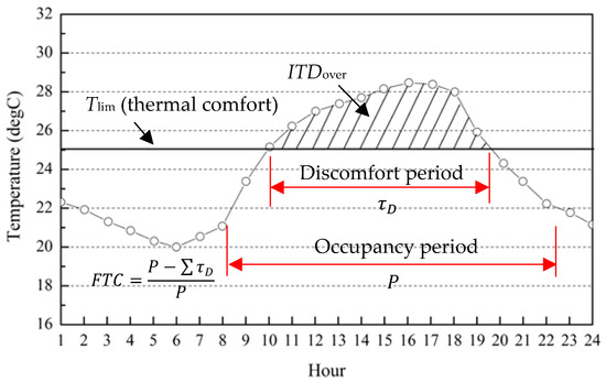
Figure 1.
ITDover and FTC: graphic definition (re-plotted after [18]).
The ITDover is defined as the time integral, over the occupancy diurnal period P, of the positive difference between the current temperature and the upper threshold for comfort [18]:
where,
where is the upper limit of comfort temperature as defined, which is usually determined based on thermal comfort associated to local climate, for instance, 27 °C is used in the literature [38]. Consider there are potentially multiple discrete discomfort periods over the occupancy diurnal period P, the in Equation (1) can be generalized as the summation of the effects over the discrete multiple periods, :
As illustrated in Figure 1, the is defined as the percentage of a discomfort period, , over the entire occupancy time:
within a given diurnal period, during which the indoor thermal comfort conditions are met. Accordingly, the generalized can be revised from Equation (4) to account for the summation over the multiple discrete periods:
3. Simulation of Thermodynamics of Building Envelopes Using Exterior Walls Reinforced by PCMs
In this section, a mathematical formalization of heat transfer of PCM-enabled building walls is first introduced, and its implementation in the numerical simulation using software COMSOL (COMSOL, Inc., Burlington, MA 01803, USA) is followed in detail, where the material, load, and boundary conditions are basically informed. A case found in the literature is used for a comparison to calibrate the parametric selection used in the model and demonstrate the accuracy of the model.
3.1. COMSOL-Based Multi-Physic Modeling of Building Envelopes
3.1.1. Overview of Formulation of the 2-D Heat Transfer and Simulation Using Multi-Physic Software COMSOL
A multi-layered wall is widely used in residential and commercial building envelopes in the United States and herein is selected as a typical representative. To characterize the dynamics of building envelopes, such as the heat transfer through a wall assembly, the transient thermal behavior of a solid could be formulated by the partial differential equation as follows:
where, T is the temperature (K), is the thermal conductivity of the material (W/m K), is the density of the material (kg/m3), and is the specific heat of the material (J/kg K). Analytical or numerical methods, such as finite difference methods, have been found in the literature through Equation (6) to formulate the heat transfer in the wall assemblies. In this study, a commercially available multi-physic software, COMSOL, was used for modeling two-dimensional (2D) heat transfer of the wall assembly [39]. For simplicity, contact resistance between different wall layers is ignored. The dynamics of phase change process from phase I (solid) to phase II (liquid) in PCM material was modeled in the COMSOL using:
where is the specific heat (J/kg K), is the latent heat of fusion (J/kg), and is:
where is the latent heat of fusion (J/kg); is the volume fraction of PCM at initial solid phase I; and the transition interval of PCM material between solid and liquid phase is not ideally zero, and is usually determined by actual material results, 5 °C by default in the COMSOL if not available.
3.1.2. COMSOL Implementation: Material, Loading and Boundary Conditions
The wall assembly is idealized as homogenous and isotropic materials in each layer, and thus its heat transfer is one-dimensional through the wall thickness. Consider there are identical properties in solid and liquid phases, the volume fraction or thermal conductivity of the PCM in Equations (7a) and (7b):
As a result, the in Equation (8) could be reduced to −0.5, and introducing them in Equation (7c) yields
Exterior boundary condition in the numerical simulation has to account for the surface temperature and solar radiation data that are generated from the anisotropic sky model typical meteorological year weather data from collection a station under summer seasons in Austin, TX. Input files containing hourly values of outdoor dry air temperature and solar radiation in the first week of June in Austin are shown in Figure 2. Note that the weather data used herein is just for demonstration, while more thermal performance could be carried out in a similar manner under the different climate zones in the United States.
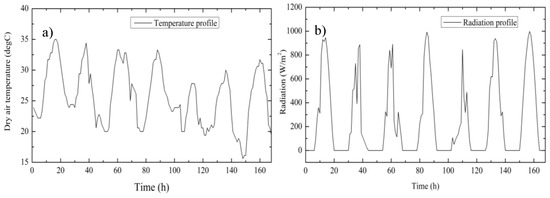
Figure 2.
(a) External dry air temperature and (b) radiation on the external surface of the wall.
3.2. Validation of the Model
A multi-layered wall configuration in the literature was used to calibrate the effectiveness of the numerical thermal analysis using the multi-physics COMSOL. As illustrated in Figure 3a, the 2D wall configuration with a PCM layer was plotted and the predicted results were compared to data found in the literature [13], where the heat transfer of the wall was mathematically formulated and solved by the finite difference method. The wall, illustrated in Figure 3b, was subjected to one-dimensional heat transfer under both top and bottom sides ideally insulated. Material properties of each wall layer are shown in Figure 3c, where the PCM has a heat of fusion of 63,000 J/kg and melting point of 24 °C. Input weather data accounted for the combined action of the dry air temperature and the solar radiation, as shown in Figure 3d. Data was captured from the interior wall surface for the comparison.
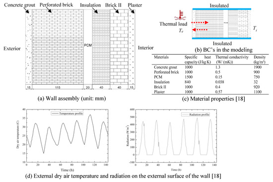
Figure 3.
The wall assembly used for the calibration.
Figure 4 shows the comparison of the temperature profiles of them when applying the input temperature and radiation after 16 h and 20 h, respectively. Clearly, the temperature gradients predicted by the COMSOL are in good agreement with the values in the literature [13]. Therefore, the model using the COMSOL multi-physics is proper to capture the transient heat transfer through the multi-layered wall system with a PCM layer. Note that there is a discrepancy between the two models near the layers of PCM and the brick II, as shown in Figure 4a. Further observations show that although it is not clear due to any reasons, the discrepancy starts at the middle of the perforated brick, where the slope of the temperature (i.e., temperature gradient) from the reference [13] gradually reduces. Also, the temperature gradient of the perforated brick is higher than that of the PCM nearby. However, based on the Fourier law of heat conduction, the temperature gradient is inversely proportional to the thermal conductivity, that is, the PCM should have a higher slope than the brick, particularly under straight heating stage, as shown in Figure 3d. A comparison shows the results predicted by COMSOL follow the correct trend, which is also confirmed by Figure 4b, where the temperature gradient from either the reference [13] or the present study is almost identical for most cases.
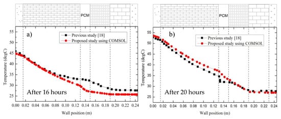
Figure 4.
Temperature profile through the wall thickness (a) after 16 h and (b) after 20 h.
3.3. Characterization of Thermodynamics of the Wall Assembly
A comprehensive study was herein conducted to gain a deep understanding of the thermodynamics of a building envelope reinforced with PCM layers under transition temperature, and to elucidate the impacts of the five different factors, including the location of the PCM layer, thickness of the PCM layer, latent heat of the PCM, melting temperature of the PCM, and thermal conductivity of the PCM, on energy efficiency.
3.3.1. Prototype of the Wall Assembly
As clearly illustrated in Figure 5, a typical multi-layered wall from the literature [40] was selected as our prototype. The wall assembly consisted of a 100-mm thick cement grout layer on the outside, a 100-mm perforated brick layer, a 40-mm layer of thermal insulation, and a 30-mm layer of PCM followed by a 20-mm oriented strand board (OSB) inside. Note that the parameters of a building in terms of thickness of thermal insulation or different assemblies should be designed to account for different locations based on climate maps through hydrothermal analysis, such as use of the commercially available software TRNSYS® (Thermal Energy System Specialists, LLC, Madison, WI 53703, USA). To perform thermal simulations using COMSOL, the thermophysical properties of each layer in a wall assembly (see Figure 5) are defined from the literature, as listed in Table 1, where the melting point of the PCM was 28 °C, and its heat of fusion was 63,000 J/kg. During the heat transient process, the entire domain was initially assumed to be 26 °C. The thermal properties of the masonry materials used in the simulation are listed in Table 1. Further parametric study, illustrated in Table 2, was conducted to explore critical factors, including the location, thickness, heat of fusion, melting point, and thermal conductivity of the PCM, and their impacts on the performance of the wall assembly.
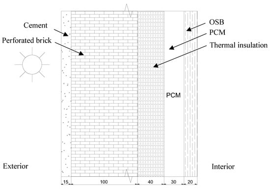
Figure 5.
A schematic diagram showing the wall assemblies of a typical external wall (unit: mm).

Table 1.
Thermophysical properties of the materials used in the building envelope assembly.

Table 2.
Test matrix of the building envelope under varying design parameters.
3.3.2. Design of Test Cases for the Parametric Study and Performance Assessment
As listed in Table 2, a total of 31 cases are designed to address the thermodynamics of building envelopes with PCM layers. All cases are consistently labeled in such a way that the first term of the labels denotes the location of the PCM, the second term “MT” denotes the melting point, and the third term “D” denotes the thickness of the PCM layer, unless otherwise stated. For example, IN-MT28-D100 in Table 2 represents the PCM layer with a thickness of 100 mm and a melting point of 28 degrees embedded near the inner layers of the wall assembly.
To elucidate the variables for determining building energy efficiency, we classified them into five different categories: (a) variability associated with the location of the PCM layer: the PCM layer, shown in Figure 6, was placed under different locations (i.e., exterior, middle or interior layer over the wall), as labelled by EX-MT24-D30, MD-MT24-D30, IN-MT24-D30, respectively; (b) variability associated with the melting point of the PCM layer: the melting point of the PCM was herein selected with a wide range from 24 to 45 °C to address their impacts to the energy efficiency of a building envelope; (c) variability associated with the thickness of the PCM layer: its range varied from zero to 100 mm; and (d) and (e) variability associated with the properties of the PCM layer, including the heat of fusion and the thermal conductivity of PCM.
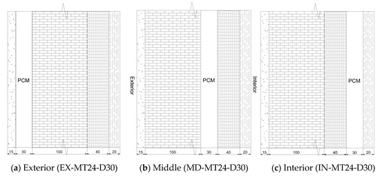
Figure 6.
Different placements of the PCM layer in the wall system.
4. Results and Discussions
4.1. Thermodynamics of Building Envelopes under Transient Temperature Field
The design of energy-efficient building envelopes necessitate a deep understanding of the dynamics of their interaction with ambient environment. In this sub-section, the first attempt was made to unveil the heating (see Figure 7a) and cooling (see Figure 7b) processes of the multi-layered wall to respond to applied transient temperature associated with air temperature and solar radiation, as shown in Figure 2. As illustrated in Figure 7a,b, typical cases under different hours were selected to demonstrate the thermodynamics of the wall over the thickness. Clearly, although the temperature outdoor increased, the gradient between indoor and outdoor temperature initialized the cooling at the initial stages, such as at five hours, as shown in Figure 7b. This is illustrated by the temperature contour in Figure 8a, where contour denotes the temperature increase from exterior to interior layers. With the increase of ambient temperature after 10 h, as shown in Figure 2 and Figure 9a, the outdoor temperature was then higher than indoor, which triggered the heating conduct from the exterior to interior wall through the thickness, as further confirmed by Figure 8b. Particularly, the heat transfer reached the higher value when at 15 h, as shown in Figure 7a. After that, the outdoor temperature dropped gradually at 25 or 30 h. Interestingly, we could observe the balanced stage near 20 h, as shown in both Figure 7c and Figure 8c, where the indoor temperature was identical to the outdoor, and a certain amount of the heat was only stored by the brick, the thicker thermal mass. Such heat transfer over the wall was cyclically repeated accompanied by the charge and discharge of the PCM layer, with cumulative residual heating indoor if without additional heating, ventilation and air-conditioning (HVAC) systems.
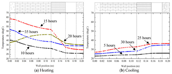
Figure 7.
Dynamics of the heating and cooling processes through the temperature profile over the wall thickness.
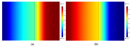
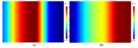
Figure 8.
Thermal contour over the wall thickness under different time periods: (a) 5 h; (b) 15 h; (c) 20 h; and (d) 25 h.
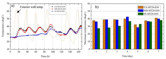
Figure 9.
History of interior wall surface temperature over time: (a) transient temperature and (b) peak temperature.
4.2. Effect of the Location of the PCM Layer within the Wall Assembly on the Thermal Performance
Previous studies [15] have showed that the PCM layer can be embedded within different locations of the wall assembly. This section is to address three different placements of the PCM layer, illustrated in Figure 5, and the impact of the placement/location of the PCM layer on the wall energy efficiency.
Figure 9a,b are plotted for transient and peak temperature profiles of the interior wall surface over time. As a comparison, the external wall surface temperature that directly responded to air temperature and solar radiation was also plotted in Figure 9a in dashed lines. Clearly all three cases showed the time delay response to the outdoor ambient temperature due to multiple layers of wall assemblies serving as thermal mass and PCM effects as well. The peak temperature swings for the three cases were 12 °C, 15 °C and 7 °C during the 7-day test period, respectively. Clearly, the PCM layer that was located near the interior of the wall, labelled as IN-MT28-D30, had the smallest temperature swings over time and the lowest maximum instantaneous temperature, as compared to the other two cases (i.e., EX-MT28-D30 and MD-MT28-D30). The maximum instantaneous temperature of the IN-MT28-D30 was only 36 °C, 13% and 16% smaller than their counterparts (41 °C for the EX-MT24-D30 and 43 °C for the MD-MT28-D30) at the first 24 h, respectively. Thus, the case of IN-MT28-D30 exhibited the most effective way to reduce the indoor temperature swings (see Figure 9a) and the peak temperatures (see Figure 9b) during both heating and cooling stages.
As defined in Equations (1)–(5), the generalized performance metrics, ITDover and FTC, were used from different perspectives to quantitatively evaluate the thermal performance of a wall, as shown in Figure 10a,d. Figure 10a displayed the results of the ITDover over time to cover the discomfort periods for occupants, when the upper threshold for the thermal comfort, Tlim, was set to 27 °C. As illustrated Figure 10a, the case of IN-MT28-D30 well outperformed the other two cases through all of time, particularly during the first and second days, which was confirmed by the values of the FTC, frequency of thermal comfort, shown in Figure 10c. Clearly, the FTC in Figure 10c revealed that IN-MT28-D30 reached up to 95% of the thermal comfort, while the other two cases also reached about 60% of the thermal comfort, suggesting that about 40% of the time remained in the discomfort period during the first day. Such efficiency further dropped to as low as 10% of the period within the thermal comfort at seven days. It is mainly because the use of passive PCM layers in the building envelopes in these three cases could reduce the peak temperature to certain levels, but may not meet the thermal comfort demand (e.g., 27 °C) in the given hot weather in Texas, which usually requires cooling through the input of HVAC systems and/or supplementary windows open at night time.
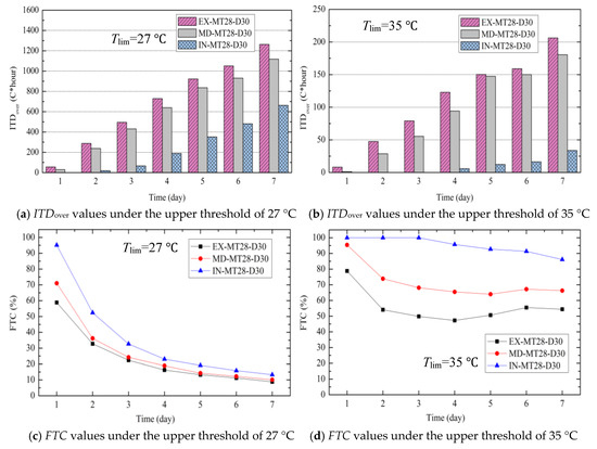
Figure 10.
Performance metrics ITDover and FTC under different placements of the PCM layer (a–d).
Therefore, if the upper temperature threshold of the thermal comfort was set up to a higher value, for instance, 35 °C, which the PCM layers may offer, we could theoretically re-assess the impacts of the location of PCM layer to the thermal performance of a building wall, as shown in Figure 10b,d. Clearly, all three cases offered high efficiency with above 80% of thermal comfort at 35 °C at the first day, while remaining above 50% or higher for the rest of the days. Figure 10b,d also confirmed the previous observation that IN-MT28-D30 could achieve the most efficiency for thermal performance.
4.3. Effect of the Melting Point of PCM on the Thermal Performance
The selection of the proper melting point of the PCM used for the multi-layered wall systems is one of the key properties of interest. In this section, a wide range of the melting points varying from 24 to 45 °C were selected to account for their impacts, while maintaining other design parameters as listed in Table 2, including the thickness of the PCM layer of 30 mm located in the interior layer, named as IN-MD**-D30.
Figure 11 shows the time series history of the interior wall surface temperature under different melting temperatures. The controlling wall without PCM layers had the highest temperature swings, ranging from 26 to 46 °C during the 7-day test period. A reduction of peak temperature was observed in all of the walls reinforced with the PCM layer, though each case displayed totally different trends. Specifically, the performance curve of the wall with a PCM layer at a melting point of 24 °C, IN-MD24-D30, was not effective to mitigate the temperature fluctuation, which was identical to the performance of IN-MD45-D30 (i.e., melting point of 45 °C). This suggested that the PCM could not be as effective as expected if the melting point was too high or too low. When the melting point of the PCM varied from 28 to 32 °C, significant reduction of the maximum instantaneous temperature and the temperature swings over the test periods were observed. Particularly, IN-MD28-D30 presented the best improvement, as compared to all other cases.
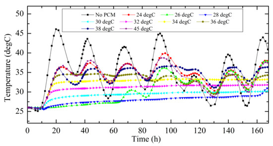
Figure 11.
Transient temperatures of the interior wall surface over time.
Further quantitative assessments were conducted using the ITDover, as plotted in Figure 12, where four different test periods were selected as the representatives. Clearly, the similar findings showed that the IN-MD28-D30 with a melting point of 28 °C exhibited a much better performance over the others, leading to the shortest discomfort period at the first day and still maintaining the higher performance as compared to other melting temperatures over time.
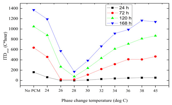
Figure 12.
Performance metrics ITDover under different melting points of the PCM layer.
4.4. Effect of the Thickness of PCM Layer on the Thermal Performance
Another piece of critical information for building designers and engineers is the determination of the thickness of PCM layers for building envelopes. Seven scenarios using three different thicknesses of PCM layers, from 7.5 to 100 mm, as well as the controlling sample without PCM, were investigated to address their effects on the thermal performance of the multi-layered wall system.
Figure 13 showed that IN-MD28-D30 achieved a reduction of 7 °C at the peak temperature and had a temperature fluctuation ranging from 25 to 35 °C, about a 55% reduction as compared to the controlling wall without PCM. Further reduction in terms of temperature swings over time and the maximum instantaneous temperature were observed with an increase of the thicknesses. During the seven-day test period, the temperature swings of these scenarios, IN-MD28-D15, IN-MD28-D30, and IN-MD28-D50, were 10 °C, 5.8 °C and 4.0 °C, respectively. A comparison further demonstrated that the maximum instantaneous temperature reductions were 30%, 55% and 60%, respectively, as shown in Figure 13b, suggesting that the thicker the PCM layer, the more latent heat of fusion it possess, which in turn results in larger thermal energy storage capacity.
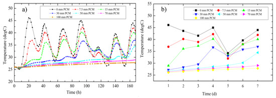
Figure 13.
History of interior wall surface temperatures over time: (a) transient temperatures and (b) peak temperatures.
Figure 14 shows the results using the performance metric ITDover under different scenarios when the upper temperature threshold Tlim was 27 °C. The seven-day ITDover of the PCM layers with different thicknesses ranging from 15 to 50 mm exhibited considerable reduction in the discomfort periods, from 29 to 79%, as compared to the controlling one during the first day, respectively. The values in Figure 14 reveal that a thicker PCM layer can exponentially improve building energy efficiency in terms of less discomfort periods.
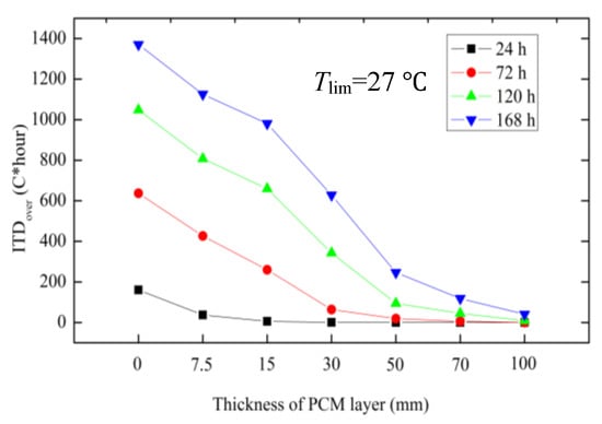
Figure 14.
Performance metric ITDover under different melting points of the PCM layer.
4.5. Effect of the Latent Heat of PCM on the Thermal Performance
The latent heat of PCM represents the capacity of energy storage, and thus selection of high latent heat of fusion could potentially provide better thermal comfort to the building systems. In this section, three different latent heat of fusions of the PCM, 63, 150 and 210 KJ/kg, were used for the investigation. The thickness of the PCM layer remained 30 mm. We used two different melting points, 24 °C and 28 °C, for a comparison.
No considerable improvement was observed for the different latent heat of fusions when the melting point of the PCM was 24 °C, which was consistent with early findings in Figure 15a. During the seven-day test period, the temperature swings of the three cases with different heat of fusions were 5.8 °C, 4.7 °C and 4.9 °C, respectively. Although the temperature swings were not influenced a lot by the heat of fusion of the PCM, the maximum instantaneous temperature of the wall with high latent of fusions had certain reduction, by 1.5%, 3.8% and 4.1%, as compared to the controlling one, at the fourth day, as shown in Figure 15a.
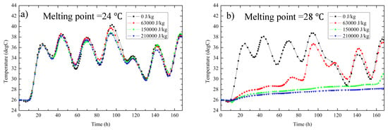
Figure 15.
Time history of interior wall surface temperatures under different melting points of the PCM layer.
Differently, by using a melting point of PCM of 28 °C, significant enhancement of the heat storage capacity could be achieved by using higher heat of fusions, as shown in Figure 15b. Clearly, when the heat of fusion reached up to 150 kJ/kg, the wall exhibited the smallest temperature swings over time and the lowest maximum instantaneous temperature, as shown in Figure 15b.
Figure 16 shows the results of the ITDover and FTC when the upper threshold of the thermal comfort was at 27 °C. The seven-day ITDover of the cases with heat of fusions of 63, 150 and 210 KJ/kg displayed a considerable decrease, by 47%, 83% and 92%, as compared to the controlling one, when the melting point was at 28 °C. Clearly, the higher the heat of fusion of the PCM was, the smaller value the ITDover was, suggesting that less discomfort periods were achieved by using the PCM. The FTC values are plotted in Figure 16b, where higher energy efficiency is observed in accordance with the higher heat of fusions, particularly during the early test periods.
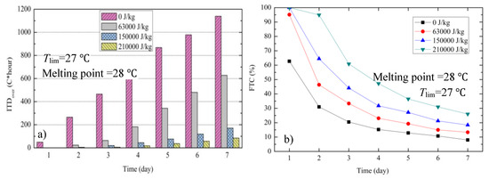
Figure 16.
Performance metrics under different heat of fusions of the PCM layer: (a) ITDover and (b) FTC.
4.6. Effect of the Thermal Conductivity of PCM on the Thermal Performance
Figure 17a,b were plotted to display the effect of thermal conductivity of PCM on the thermal performance of the multi-layered wall system. The investigation focused on the thermal conductivity of the PCM layer ranging from 0.15 to 1.0 W/mK. Figure 17a showed that there were identical trends for the interior wall surface temperature. During the seven-day test period, the temperature swings of the four scenarios were relatively small within 6 °C (i.e., 5.8 °C, 4.7 °C, 5.6 °C and 5.7°C, respectively). Also, Figure 17b reveals that the maximum instantaneous temperatures for all of the four scenarios were pretty identical, suggesting that the thermal conductivity of the PCM layer had a negligible impact on the thermal performance of the wall system.

Figure 17.
History of interior wall surface temperatures over time: (a) transient temperature and (b) peak temperature.
Moreover, Figure 18 shows the findings from the ITDover and FTC. No considerable improvement was observed when changing the thermal conductivity of the PCM layer. The results shown in Figure 18a,b suggest that the less thermal conductivity the material had, the slightly higher insulation to the heat transfer it had. The FTC confirmed that the PCM layer with a thermal conductivity of 0.15 W/mK had a slight improvement for the thermal performance of the wall.
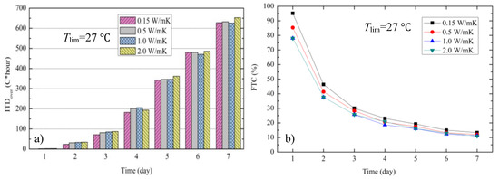
Figure 18.
Performance metrics under different heat of fusions of the PCM layer: (a) ITDover and (b) FTC.
4.7. Summary of the Parameter Selection of PCM for Building Energy Efficiency
The detailed investigation of PCMs regarding its properties and design variables for building applications has been presented in Section 4.1, Section 4.2, Section 4.3, Section 4.4, Section 4.5 and Section 4.6, including placement of PCM layer, its melting point, its thickness, and its heat of fusion and thermal properties, as summarized in Figure 19a–e. For simplicity, one performance metric, FTC, was only selected to quantitatively assess their attributes to building energy savings in terms of the ratio of comfort period over total occupancy time.
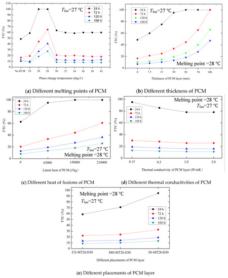
Figure 19.
Performance metric FTC for the PCM-enabled wall assembly under different design variables.
In general, though each design variable exhibits high variation in building energy savings, the building performance may be affected by complex interaction of these factors under transient building environments. These parameters could be interrelated. For instance, the selection of heat of fusions of PCM is highly affected by the melting points of PCM, which could be observed in Figure 15. A comparison of Figure 19a–e for all of design variables revealed that the PCM melting point, thickness, and the heat of fusion are the more dominant for attributes to the building energy efficiency. Specifically, the cases where the PCM has a melting point of 28 °C, with its thickness of 30 mm or more, and the heat of fusion of 64 kJ/kg or higher could reach up to 100% thermal comfort at the first day without any additional cooling supply. With the increase of the test time, all cases exhibited reduced thermal performance due to cumulative heating indoor. At the end of the seven-day testing period, the most effective way to achieve energy-efficiency building envelopes was by using thicker PCM layers (up to 100 mm), with nearly 50% thermal comfort, as compared to as low as 6% thermal comfort for non-PCM cases or other cases at about 10%.
As stated earlier, the selection of a proper melting point could help to save cooling energy or prevent overheating. Figure 19c shows that the melting point of the PCM at 28 °C could be the more efficient, while the average of indoor temperatures under non-PCM cases was about 28.7 °C at the first day and 30~32 °C during the seven days. Some researchers [31] suggest that the melting temperature of PCM can be selected near the average indoor air temperature, which partially confirms the observations in this study, though the other heating gains under different weather conditions could make a wide temperature range.
Moreover, as illustrated in Figure 19e, the placement of PCM layers near the indoor could offer more energy savings for a building, as compared to other cases at central or exterior layers.
5. Further Discussions of PCMs to Space Heating and Cooling Load Reduction
The efforts above have been made to address the impacts of different design variables to the thermodynamics of the PCM-based walls. Despite the previous studies that have been conducted to discuss the multiple layers of PCMs and different placements within the wall assembly, few of which addressed the impacts of the multiple layers of PCMs with mismatched melting points. In this section, the multi-layered wall shown in Figure 5 was modified by adding an additional one 30-mm thick layer of PCM near the exterior brick. For simplicity, the melting point of PCM at the exterior layer varying from 28 to 40 °C was the only parameter in the discussion, as listed in Table 3, where the cases were labeled as the IN-MT28-D30-EX**-28, and “EX**” denotes the additional exterior PCM layer at a certain melting point. A comparison shown in Figure 20 and Figure 21 demonstrates that the multiple layers of PCMs with mismatched melting points considerably promoted the energy efficiency of a building, as compared to the single PCM one. Particularly a reduction of 4 degrees was observed after a 10-h period for the exterior PCM layer with a melting point of around 35 °C, as compared to the single PCM one. The ITDover values in Figure 20 confirmed that all cases behaved identically during the early hours, and the two-layer PCM-enabled walls could achieve higher energy storage in terms of less discomfort periods after 5–7 days.

Table 3.
Design of multiple layers of PCM in the wall.
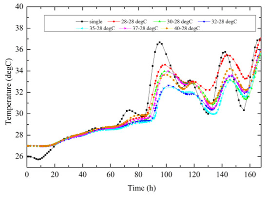
Figure 20.
Time series of the interior wall surface temperature.
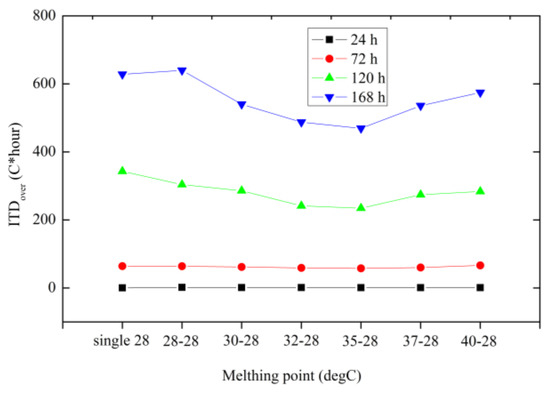
Figure 21.
ITDover of different cases under the threshold of 27 °C.
6. Conclusions
This study numerically investigated the thermal performance of a multi-layered PCM-enabled wall assembly and its dynamics under varying design variables, including placement of PCM layers and their thickness, and the properties of PCM (e.g., latent heat, melting temperature of PCM, and thermal conductivity). The results were quantitatively evaluated using four performance metrics: temperature swing, maximum instantaneous temperature, and the ITDover and FTC, with specific conclusions as shown below:
- (a)
- Each design variable exhibited high variation in attributes to building energy savings in terms of reduction of peak temperature and temperature swings. A comparison clearly demonstrated that the melting point of PCM, its thickness, and heat of fusion were crucial parameters to promote building energy efficiency, while its thermal conductivity seemed insensitive to the energy storage capacity. Specifically, the selection of the proper melting point highly aligned with the local climate zones and thermal comfort demand, and was often selected 1–2 °C above the indoor air temperature, as confirmed in the literature. The results also demonstrated that the heat of fusions of PCM with 64 kJ/kg or higher could significantly enhance the energy storage capacity with applications to buildings. A comparison of different thicknesses of the PCM layer further demonstrated the energy efficiency of PCM with applications to the wall assembly. For instance, a reduction of the maximum instantaneous temperature reached up to 30% when using only a 15-mm thick PCM layer in a conventional 185-mm thick wall, as compared to the no-PCM one.
- (b)
- In the context of placement of PCM layer in a building envelope assembly, researchers have not reached a consensus on which is an optimal solution when subjected to ambient environment. For design of a single layer of PCM in a building envelope, this study showed that the placement of the PCM near the interior wall surface could achieve more efficiency than other cases. It should be noted that if the selected melting point is not proper, there will be no significant differences regardless of wherever the PCM is placed. For multiple layers of PCMs, a further discussion showed that the building could exhibit higher energy efficiency if the inner PCM has a melting point near the averaged indoor air temperature and the outer layer of PCM has a melting point close to the averaged outdoor air temperature.
- (c)
- Four performance metrics could provide different perspectives for the evaluation of building energy efficiency; as compared to discrete peak temperature or temperature swings, the ITDover and FTC could provide systematic information of discomfort period over time, and thus be effective tools for quantifying the thermal performance of a PCM-enabled building.
- (d)
- It should be noted that there are herein no thermal analyses of entire buildings with other energy demands and/or interaction with HVAC systems. Further investigation of entire buildings, such as using Energyplus, is needed, particularly for thermodynamic analysis under more complex climate and building environments, where more coupled information could affect the building energy efficiency.
Author Contributions
M.L. and Z.L. had the original idea for the study. M.L. was responsible for simulation and data analysis with assistance of H.P. and X.W. M.L. and Z.L. drafted the manuscript. G.G. and L.J. reviewed and revised the manuscript.
Funding
National Natural Science Foundation of China (No. 51468023), USDOT (FAR0025913) and USA DOT CAAP (FAR0026526), ND NSF EPSCoR Seed Grant.
Acknowledgments
The authors gratefully acknowledge the financial support provided by National Natural Science Foundation of China (No. 51468023), ND NSF EPSCoR Seed Grant, USDOT (FAR0025913) and USA DOT CAAP (FAR0026526). The results, discussion, and opinions reflected in this paper are those of the authors only and do not necessarily represent those of the sponsors.
Conflicts of Interest
The authors declare no conflicts of interest.
References
- Baetens, R.; Jelle, B.P.; Gustavsen, A. Phase Change Materials for Building Applications: A State-of-the-art Review. Energy Build. 2010, 42, 1361–1368. [Google Scholar] [CrossRef]
- Ramakrishnan, S.; Sanjayan, J.; Wang, X.; Alam, M.; Wilson, J. A Novel Paraffin/expanded Perlite Composite Phase Change Material for Prevention of PCM Leakage in Cementitious Composites. Appl. Energy 2015, 157, 85–94. [Google Scholar] [CrossRef]
- Zhou, D.; Zhao, C.Y.; Tian, Y. Review on Thermal Energy Storage with Phase Change Materials (PCMs) in Building Applications. Appl. Energy 2012, 92, 593–605. [Google Scholar] [CrossRef]
- Zhu, N.; Ma, Z.; Wang, S. Dynamic Characteristics and Energy Performance of Buildings Using Phase Change Materials: A Review. Energy Convers. Manag. 2009, 50, 3169–3181. [Google Scholar] [CrossRef]
- Sharma, A.; Tyagi, V.V.; Chen, C.R.; Buddhi, D. Review on Thermal Energy Storage with Phase Change Materials and Applications. Renew. Sustain. Energy Rev. 2009, 13, 318–345. [Google Scholar] [CrossRef]
- Memon, S.A. Phase Change Materials Integrated in Building Walls: A State of the Art Review. Renew. Sustain. Energy Rev. 2014, 31, 870–906. [Google Scholar] [CrossRef]
- Khudhair, A.M.; Farid, M.M. A Review on Energy Conservation in Building Applications with Thermal Storage by Latent Heat Using Phase Change Materials. Energy Convers. Manag. 2004, 45, 263–275. [Google Scholar] [CrossRef]
- Akeiber, H.; Nejat, P.; Majid, M.Z.A.; Wahid, M.A.; Jomehzadeh, F.; Famileh, I.Z.; Calautit, J.K.; Hughes, B.R.; Zaki, S.A. A Review on Phase Change Material (PCM) for Sustainable Passive Cooling in Building Envelopes. Renew. Sustain. Energy Rev. 2016, 60, 1470–1497. [Google Scholar] [CrossRef]
- Karaipekli, A.; Biçer, A.; Sarı, A.; Tyagi, V.V. Thermal Characteristics of Expanded Perlite/paraffin Composite Phase Change Material with Enhanced Thermal Conductivity Using Carbon Nanotubes. Energy Convers. Manag. 2017, 134, 373–381. [Google Scholar] [CrossRef]
- Lei, J.; Yang, J.; Yang, E.H. Energy Performance of Building Envelopes Integrated with Phase Change Materials for Cooling Load Reduction in Tropical Singapore. Appl. Energy 2016, 162, 207–217. [Google Scholar] [CrossRef]
- Seong, Y.B.; Lim, J.H. Energy Saving Potentials of Phase Change Materials Applied to Lightweight Building Envelopes. Energies 2013, 6, 5219–5230. [Google Scholar] [CrossRef]
- Wang, X.; Yu, H.; Li, L.; Zhao, M. Experimental Assessment on the Use of Phase Change Materials (PCMs)-bricks in the Exterior Wall of a Full-scale Room. Energy Convers. Manag. 2016, 120, 81–89. [Google Scholar] [CrossRef]
- Izquierdo-Barrientos, M.A.; Belmonte, J.F.; Rodríguez-Sánchez, D.; Molina, A.E.; Almendros-Ibáñez, J.A. A Numerical Study of External Building Walls Containing Phase Change Materials (PCM). Appl. Therm. Eng. 2012, 47, 73–85. [Google Scholar] [CrossRef]
- Jin, X.; Medina, M.A.; Zhang, X. Numerical Analysis for the Optimal Location of a Thin PCM Layer in Frame Walls. Appl. Therm. Eng. 2016, 103, 1057–1063. [Google Scholar] [CrossRef]
- Zwanzig, S.D.; Lian, Y.; Brehob, E.G. Numerical Simulation of Phase Change Material Composite Wallboard in a Multi-layered Building Envelope. Energy Convers. Manag. 2013, 69, 27–40. [Google Scholar] [CrossRef]
- Cabeza, L.F.; Castellon, C.; Nogues, M.; Medrano, M.; Leppers, R.; Zubillaga, O. Use of Microencapsulated PCM in Concrete Walls for Energy Savings. Energy Build. 2007, 39, 113–119. [Google Scholar] [CrossRef]
- Kuznik, F.; Virgone, J. Experimental Assessment of a Phase Change Material for Wall Building Use. Appl. Energy 2009, 86, 2038–2046. [Google Scholar] [CrossRef]
- Evola, G.; Marletta, L.; Sicurella, F. A Methodology for Investigating the Effectiveness of PCM Wallboards for Summer Thermal Comfort in Buildings. Build. Environ. 2013, 59, 517–527. [Google Scholar] [CrossRef]
- Evola, G.; Marletta, L. The Effectiveness of PCM Wallboards for the Energy Refurbishment of Lightweight Buildings. Energy Proc. 2014, 62, 13–21. [Google Scholar] [CrossRef]
- Song, J.H.; Jin, H.S.; Jeong, S.G.; Kim, S.; Song, S.Y.; Lim, J.H. Empirical Validation of Heat Transfer Performance Simulation of Graphite/PCM Concrete Materials for Thermally Activated Building System. Int. J. Polym. Sci. 2017, 2017, 6792621. [Google Scholar] [CrossRef]
- Agyenim, F.; Hewitt, N.; Eames, P.; Smyth, M. A Review of Materials, Heat Transfer and Phase Change Problem Formulation for Latent Heat Thermal Energy Storage Systems (LHTESS). Renew. Sustain. Energy Rev. 2010, 14, 615–628. [Google Scholar] [CrossRef]
- Ip, K.; Ceng, M.; Bsc, J.G. Thermal Storage for Sustainable Dwellings. K000 Archit. Build. Plan. 2000. [Google Scholar]
- Jeong, S.G.; Chang, S.J.; Wi, S.; Kang, Y.; Lim, J.H.; Chang, J.D.; Kim, S. Energy Efficient Concrete with N-octadecane/xGnP SSPCM for Energy Conservation in Infrastructure. Constr. Build. Mater. 2016, 106, 543–549. [Google Scholar] [CrossRef]
- Li, M.; Lin, Z.; Wu, L.; Wang, J.; Gong, N. Applications of Graphite-enabled Phase Change Material Composites to Improve Thermal Performance of Cementitious Materials. Mater. Sci. Eng. 2017, 264, 012013. [Google Scholar] [CrossRef]
- Zhang, Z.; Shi, G.; Wang, S.; Fang, X.; Liu, X. Thermal Energy Storage Cement Mortar Containing N-octadecane/expanded Graphite Composite Phase Change Material. Renew. Energy 2013, 50, 670–675. [Google Scholar] [CrossRef]
- Li, M.; Lin, Z.; Yan, F. Graphite-Enabled Phase Change Material Composites for Enhanced Thermal Management of Concrete Pavement. Transp. Res. Board. 2017, 17, 03915. [Google Scholar]
- Trelles, J.P.; Dufly, J.J. Numerical Simulation of Porous Latent Heat Thermal Energy Storage for Thermoelectric Cooling. Appl. Therm. Eng. 2003, 23, 1647–1664. [Google Scholar] [CrossRef]
- Li, M.; Gong, N.; Wang, J.; Lin, Z. Phase Change Material for Thermal Management in 3D Integrated Circuits Packaging. Int. Microelectron. Assem. Packag. Soc. 2015, 1, 000649–000653. [Google Scholar] [CrossRef]
- Mengjie, S.; Fuxin, N.; Ning, M.; Yanxin, H.; Shiming, D. Review on Building Energy Performance Improvement Using Phase Change Materials. Energy Build. 2018, 158, 776–793. [Google Scholar]
- Farid, M.M.; Khudhair, A.M.; Razack, S.A.K.; Al-Hallaj, S. A Review on Phase Change Energy Storage: Materials and Applications. Energy Convers. Manag. 2004, 45, 1597–1615. [Google Scholar] [CrossRef]
- Soares, N.; Costa, J.J.; Gaspar, A.R.; Santos, P. Review of Passive PCM Latent Heat Thermal Energy Storage Systems towards Buildings’ Energy Efficiency. Energy Build. 2013, 59, 82–103. [Google Scholar] [CrossRef]
- Jing, Y.H. Research on the Application and Energy-Saving Assessment of Phase Change Materials in Intelligence Architectural. Appl. Mech. Mater. 2013, 416–417, 1741–1745. [Google Scholar] [CrossRef]
- Kuznik, F.; Virgone, J.; Noel, J. Optimization of a Phase Change Material Wallboard for Building Use. Appl. Therm. Eng. 2008, 28, 1291–1298. [Google Scholar] [CrossRef]
- Lee, K.O.; Medina, M.A.; Raith, E.; Sun, X. Assessing the Integration of a Thin Phase Change Material (PCM) Layer in a Residential Building Wall for Heat Transfer Reduction and Management. Appl. Energy 2015, 137, 699–706. [Google Scholar] [CrossRef]
- Xu, X.; Zhang, Y.; Lin, K.; Di, H.; Yang, R. Modeling and Simulation on the Thermal Performance of Shape-stabilized Phase Change Material Floor Used in Passive Solar Buildings. Energy Build. 2005, 37, 1084–1091. [Google Scholar] [CrossRef]
- Zhu, N.; Liu, F.; Liu, P.; Hu, P.; Wu, M. Energy Saving Potential of a Novel Phase Change Material Wallboard in Typical Climate Regions of China. Energy Build. 2016, 128, 360–369. [Google Scholar] [CrossRef]
- Jayalath, A.; San Nicolas, R.; Sofi, M.; Shanks, R.; Ngo, T.; Aye, L.; Mendis, P. Properties of Cementitious Mortar and Concrete Containing Micro-encapsulated Phase Change Materials. Constr. Build. Mater. 2016, 120, 408–417. [Google Scholar] [CrossRef]
- De Dear, R.J.; Brager, G.S. Thermal Comfort in Naturally Ventilated Buildings: Revisions to ASHRAE Standard 55. Energy Build. 2002, 34, 549–561. [Google Scholar] [CrossRef]
- Sharifi, N.P.; Freeman, G.E.; Sakulich, A.R. Using COMSOL Modeling to Investigate the Efficiency of PCMs at Modifying Temperature Changes in Cementitious Materials–Case Study. Constr. Build. Mater. 2015, 101, 965–974. [Google Scholar] [CrossRef]
- Fang, Y. A Comprehensive Study of Phase Change Materials (PCMs) for Building Walls Applications. Ph.D. Thesis, University of Kansas, Lawrence, KS, USA, 9 March 2009. [Google Scholar]
© 2018 by the authors. Licensee MDPI, Basel, Switzerland. This article is an open access article distributed under the terms and conditions of the Creative Commons Attribution (CC BY) license (http://creativecommons.org/licenses/by/4.0/).